Article

Integrated Sensing and Communication Beamforming Design in RIS-Assisted Symbiotic Radio System

Department of Communication Science and Engineering, Fudan University, Shanghai 200433, China
*
Author to whom correspondence should be addressed.
Electronics 2025, 14(10), 2016; https://doi.org/10.3390/electronics14102016
Submission received: 6 April 2025 / Revised: 6 May 2025 / Accepted: 14 May 2025 / Published: 15 May 2025

Abstract

:
This paper aims to facilitate the integration of integrated sensing and communication (ISAC) and symbiotic radio (SR), which studies a reconfigurable intelligent surface (RIS)-assisted ISAC-SR system in single-user and multi-user scenarios. In the ISAC-SR system, a base station (BS) transmits the downlink signal to the user while sensing multiple targets. The RIS reflects the BS signal by adjusting its reflection coefficient and embeds its data for user transmission. We aim to maximize the communication rate of RIS by optimizing the transmit beamformers and RIS phase shift matrix while meeting the minimum quality of service (QoS) requirement for BS data transmission and targets sensing. Due to the non-convexity of the formulated problem, in the single-user case, we develop an alternating optimization (AO) algorithm using a semidefinite relaxation (SDR) and the Dinkelbach method to transform it into a convex problem. In the multi-user case, we leverage SDR and successive convex approximation (SCA) to obtain a suboptimal solution and prove that a rank-one solution is guaranteed. Numerical results validate the effectiveness of our proposed schemes.

1. Introduction

Integrated sensing and communication (ISAC) is recognized as one of the key technologies for the sixth generation (6G) mobile communication systems [1,2,3]. Early implementations of ISAC focused on the coexistence of radar and communication systems within the same frequency band. These two systems are deployed with separate hardware infrastructures while exchanging auxiliary information to enable coordination. In [4], the authors proposed an opportunistic spectrum-sharing mechanism, in which the communication system transmits signals when the spectral resource is not occupied by the radar system. This approach imposes serious conflicts between the radar and communication systems. To address this limitation, in [5], a null-space projection technique projects the multiple-input multiple-output (MIMO) radar beamforming vectors onto an orthogonal subspace of the interference channel. Such beamforming strategies might degrade radar performance. Thus, in [6,7], the authors investigated the trade-off between radar and communication performance by optimizing projection matrices, which impose controlled interference on the communication system.
To achieve higher spectrum efficiency and improved resource management, a dual-functional radar communication (DFRC) system has been proposed as a new solution for ISAC [8,9,10]. By jointly designing waveforms, the DFRC system effectively mitigates inter-system interference. In [11,12], a beamforming scheme based on the semidefinite relaxation (SDR) method was proposed to minimize the matching error between radar beampatterns under communication constraints. In [13], the authors used the transmit beampattern as a constraint to ensure sensing performance and solved the problem of fully connected hybrid beamforming in a multi-user and multi-beam scenario. In [14], the authors developed a joint transceiver beamforming scheme that maximizes the signal-to-interference-plus-noise ratio (SINR) at the radar receiver while satisfying the sum rate constraint for multi-user downlink communications. But this approach sacrifices radar performance to guarantee communication rates. As a step further, the authors of [15] proposed a novel beamforming design that leverages the multi-stream MIMO transmissions to achieve maximum communication rates while matching the predefined radar beampattern.
Due to the advantages of enabling low-power communication, backscatter communication has been viewed as a promising technique in ISAC systems. But backscatter communication systems face limitations from dedicated radio frequency (RF) chains. This results in high costs for large-scale deployment. Thus, ambient backscatter communication was proposed [16]. Instead of relying on dedicated RF emitters, it modulates information by leveraging existing ambient orthogonal frequency division multiplexing (OFDM) signals. The integration of sensing and communication has been studied in ambient backscatter communication systems [17]. The backscatter device (BD) modulates information via OFDM signals to enable joint localization and detection. As a step forward, in [18], a BD and a full-duplex BS transmit data to users while the BS extracts environmental information by sensing mutual information. To detect backscattered signals from multiple devices and sense targets based on echo signals, an optimization problem was proposed in [19].
Symbiotic radio (SR) has been proposed as an innovative technology for backscatter communication to achieve higher energy efficiency [20]. In a SR system, both the primary transmitter and the BD transmit communication symbols. The primary receiver applies a joint decoding mechanism to process composite signals. Compared to ambient backscatter communication, the SR system enables the BD to not only share spectrum resources and RF source with the primary link, but also achieve hardware reuse at the receiver. A random code division multiple access (CDMA) scheme was proposed to formulate a max-min SINR problem under primary communication constraints [21]. The authors of [22] maximized the weighted sum rate of primary communication and backscatter communication in the SR system. Based on time division multiple access (TDMA), the authors studied an energy efficiency maximization problem in SR systems [23]. To maximize the energy efficiency, a beamforming design was represented in [24]. In [25], a full-duplex secondary transmitter was considered to jointly optimize the beamformer and the weighted power coefficients.
The application of a reconfigurable intelligent surface (RIS) in ISAC and SR has gained growing attention due to its low cost and reflective property. For the RIS-assisted SR system in the single-user case, study [26] optimized the transmit power by applying a binary modulation mechanism to encode signals, while simultaneously improving primary transmission. In the multi-user case, a joint optimization was proposed for active beamforming at the primary transmitter and passive beamforming at the RIS to minimize energy consumption [27]. The works [26,27] focused on a point-to-point transmission framework. The authors of [28] developed an alternating optimization (AO)-based scheme for broadcast signals, which dynamically adjusts the RIS phase shift matrix to minimize the total transmit power. In [29], the authors pioneered the integration of ISAC and RIS-assisted SR systems while proposing an ISAC-SR framework.
Inspired by ISAC and SR systems, this paper studies the integration of ISAC and RIS-assisted SR. Unlike [26,27,28], which only considered RIS-assisted communication in the SR system, our beamforming design provides both accurate sensing and guaranteed communication rate. Ref. [29] approximated the sensing performance using the signal-to-noise ratio (SNR) received from echo signals. It cannot guarantee stringent sensing quality, as MIMO radar sensing strongly relies on the transmit covariance of waveforms. To this end, in this paper, we develop a transmit beamforming design in an ISAC-SR system and utilize the matching error of beampatterns as a precise metric for the sensing performance. Then, we maximize the transmission rate of the RIS-aided link, subject to the SINR constraint for the primary communication and the beampattern constraint for the sensing performance. To solve the non-convex problem, we adopt Dinkelbach and successive convex approximation (SCA) methods to jointly optimize beamformers and RIS reflection coefficients.
The main contributions of this work are summarized as follows:
  • We develop novel beamforming designs of ISAC-SR systems in both single-user and multi-user scenarios. The joint active transmit beamforming and passive reflecting beamforming design problem is formulated to maximize the transmission rate of the RIS-aided link under a given SINR constraint for the primary communication and a given beampattern constraint for the sensing performance.
  • In the single-user case, we address the formulated non-convex problem by decomposing the problem into two subproblems. For the first subproblem, a covariance matrix is proposed to construct the sensing and communication beamforming. Then, the subproblem is solved via SDR and Dinkelbach methods. For the second subproblem, based on the properties of matrix trace operations, we transform the objective function and the intended optimization problem can be solved by using SDR.
  • In the multi-user case, the SCA method is adopted to approximate the objective function via first-order Taylor expansion, which transforms the original problem into a tractable convex problem. Moreover, the rank-one property of the relaxed covariance matrix is rigorously proven, so that the beamforming can be derived by performing eigenvalue decomposition. Numerical results validate the effectiveness of our proposed schemes.
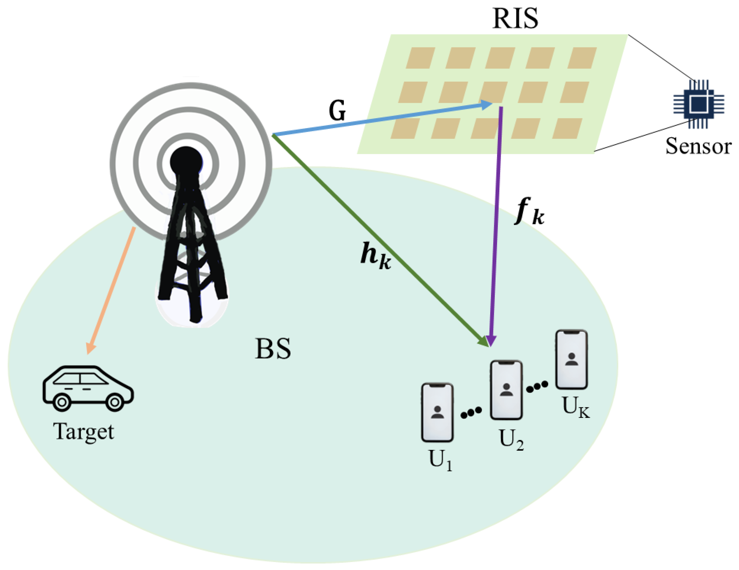
The rest of this paper is structured as follows: Section 2 outlines the system model and describes the criteria for evaluating communication and sensing performance. Section 3 derives the beamforming design in the single-user case. Section 4 develops a SCA-based algorithm to obtain a suboptimal rank-one solution in the multi-user case. Section 5 provides the simulation outcomes, followed by the conclusions in Section 6.
Notation: Scalars are represented using letters in standard font. Vectors and matrices are denoted by boldface lowercase and boldface uppercase letters, respectively. The operators ( · ) T , ( · ) * , ( · ) H , Tr ( · ) , Rank ( · ) , and diag ( · ) signify the transpose, conjugate, conjugate transpose, trace, rank, and diagonal operation of a matrix, respectively. We use · to denote the modulus of a vector/matrix, and · F is the Frobenius norm. For a symmetric matrix A , A 0 signifies that the matrix is positive semidefinite. I m , n stands for the m × n identity matrix. C m × n stands for the set of m × n complex matrices. E { · } represents taking the ensemble expectation. CN ( · , · ) represents the complex Gaussian distribution.

2. System Model

Figure 1 depicts a RIS-assisted ISAC-SR broadcasting system, where a BS is equipped with M antenna to send information to K downlink single-antenna users denoted as U k , k { 1 , , K } and detects L distant targets. Consider a RIS with E elements where each element is denoted as e { 1 , , E } . At times t, communication and sensing symbol are precoded into the transmit signal x ( t ) :
x ( t ) = w r s ( t ) + w c c ( t ) ,   t = 0 , 1 , .
where c ( t ) is the communication symbol, undergoing precoding through a beamforming vector w c C M × 1 , and s ( t ) is the sensing symbol with a beamforming vector w c C M × 1 . Without loss of generality, we assume that both symbols have been normalized so that the transmit power is unity. It is also assumed that the communication symbol and the sensing symbol are irrelevant, i.e., E { c ( t ) s H ( t ) } = 0 .
The received signal at the k-th user is written as
y k ( t ) = h k H x ( t ) + f k H Θ Gx ( t ) a + n k ( t )
where the RIS data can be represented as a, Θ is the RIS phase shift matrix, and Θ = diag ( v ) . In addition, v = [ e j θ 1 , e j θ 2 , , e j θ N ] for all θ n [ 0 , 2 π ) ; n k ( t ) CN ( 0 , σ k 2 ) represents additive white Gaussian noise (AWGN) at the k-th user. Denoting G C E × M , h k C M × 1 and f k C E × 1 as complex baseband equivalent channels from BS to RIS, BS to the k-th user, and RIS to the k-th user, respectively. We assume that the channels consist of two components, i.e., a large-scale fading component and a small-scale Rician fading component [26].

2.1. Sensing Performance Guarantee

In the ISAC system, the communication signal is perfectly known at the BS. Under the assumption that the transmission waveform is narrowband and the propagation path is line-of-sight (LoS), the baseband signal in the θ direction can be expressed as
x ˜ ( t ; θ ) = a H ( θ ) x ( t )
where a H ( θ ) = [ 1 , e j 2 π δ s i n ( θ ) , , e j 2 π ( M 1 ) δ s i n ( θ ) ] T , with δ being the normalized antenna spacing at a given wavelength. The accuracy of the sensing performance is related to the beampattern, which depends on the covariance matrix of the transmitted signal. We denote R x = E { x ( t ) x H ( t ) } to be the cross-correlation of x ( t ) . Then, the beampattern at θ direction is given by
P ( θ ; R x ) = E { x ˜ ( θ ; t ) x ˜ H ( θ ; t ) } = a H ( θ ) R x a ( θ )
The mean square error (MSE) between the desired and transmit beampattern is used to represent the sensing performance, i.e.,
L ( R x ) = 1 L l = 1 L | d ( θ l ) P ( θ l ; R x ) | 2
where L is the number of sensing target, d ( θ l ) is the given desired beampattern, { θ l } l = 1 L are sampled angle grids. Then, the best perception accuracy is obtained by solving the following optimization problem that only considers the sensing performance:
(6a) min R x L ( R x ) (6b) s . t . [ R x ] m , m = P t M ,   m = 1 , , M (6c) R x 0

2.2. Communication Performance Metric

To recover the data transmitted by the RIS at the receiver, the communication user employs successive interference cancellation (SIC) to jointly decode the signals of the BS and the RIS. Specifically, the user first decodes the signal transmitted by the BS, subtracts the successfully decoded communication symbol c ( t ) from the received signal y k ( t ) , and then performs SIC decoding on the signal sent by the RIS. Thus, after the communication symbol removal, the received signal (2) may be expressed as
y s , k ( t ) = h k H w r s ( t ) + Q k w r s ( t ) + w c c ( t ) a + n ( t )
where Q k = f k H Θ G = f k H diag ( v ) G . From (2), the SINR at the k-th user for decoding c ( t ) is given by
γ c , k = h k H w c w c H h k + Q k w c w c H Q k H h k H w r w r H h k + Q k w r w r H Q k H + σ 2
From (7), after applying SIC, the received SINR at the k-th user for decoding a is given by
γ a , k = Q k ( w c w c H + w r w r H ) Q k H h k H w r w r H h k + σ 2

3. Beamforming Design in Single-User Case

3.1. Problem Formulation

Consider first the single-user case, i.e., there only exists K = 1 user. We wish to maximize the SINR between the RIS and the user without affecting the sensing and communication performance of the BS. Therefore, we have the following optimization problem:
(10a) max w c , w r , v γ a (10b) s . t . γ c Γ c (10c) 1 L l = 1 L | d ( θ l ) a H ( θ l ) ( w c w c H + w r w r H ) a ( θ l ) | 2 β (10d) [ w r w r H + w c w c H ] m , m = P t M ,   m = 1 , , M (10e) [ vv H ] e , e = 1 ,   e = 1 , , E
where constraint (10b) ensures the minimum SINR for BS data decoding, (10d) is the per-antenna power constraint, P t is the total transmit power, (10e) is the constant modulus constraint of the RIS, (10c) indicates that the MSE between the desired and actual beampattern should be small enough to ensure the directivity of the sensing symbol. The value of β is obtained by solving the problem (6).
The joint optimization of the beamforming vectors and the RIS phase shift matrix as well as the non-convexity of the objective function and constraints in (10) make it challenging to solve (10). To address problem (10), we first denote a new vector that contains all beamforming vectors, that is, w = [ w c T , w r T ] T C 2 M × 1 , and R = ww H C 2 M × 2 M is the covariance matrix of the vector. We then define the selection matrices as
D c = [ diag ( I M × 1 ) , 0 M × M ] C M × 2 M D r = [ 0 M × M , diag ( I M × 1 ) ] C M × 2 M
such that w c = D c w ,   w r = D r w . Our goal is to solve the problem by optimizing { w , v } . Our approach utilizes the AO algorithm to address this challenge. Specifically, we optimize variables alternately so that each variable is optimized while the other variable is fixed. The process is repeated until it converges.

3.2. Beamforming Vector Optimization

The SDR method is deployed here to address the problem (10). After relaxing the rank-one constraint, (10) can be transformed as follows:
(12a) max R QD c RD c H Q H + QD r RD r H Q H h H D r RD r H h + σ 2 (12b) s . t . Γ c 1 ( h H D c RD c H h + QD c RD c H Q H ) h H D r RD r H h + QD r RD r H Q H + σ 2 (12c) 1 L l = 1 L | d ( θ l ) a H ( θ l ) ( D c RD c H + D r RD r H ) a ( θ l ) | 2 β (12d) [ D c RD c H + D r RD r H ] m , m = P t M ,   m = 1 , , M (12e) R 0
Then we use the Dinkelbach technique [30] to rewrite (12) into a tractable formulation as
max R QD c RD c H Q H + QD r RD r H Q H λ ( QD r RD r H Q H + σ 2 ) s . t . ( 12 b ) ( 12 e )
where λ = QD c R * D c H Q H + QD r R * D r H Q H QD r R * D r H Q H + σ 2 is related to the optimal solution at each iteration. The problem (13) becomes a standard convex problem. We can use CVX to find a suboptimal solution [31].

3.3. RIS Reflection Coefficient Optimization

This subsection aims to solve the RIS phase shift optimization problem while keeping the beamforming vector constant. We first transform the expression of γ a
(14a) γ a = ( a ) v H d i a g ( f H ) G ( w c w c H + w r w r H ) G H d i a g H ( f H ) v h H w r w r H h + σ 2 (14b) = v H M ( D c RD c H + D r RD r H ) M H v h H D r RD r H h + σ 2 (14c) = ( b ) T r ( M ( D c RD c H + D r RD r H ) M H vv H ) h H D r RD r H h + σ 2 (14d) = T r ( ZV ) h H D r RD r H h + σ 2
Equation (a) is derived from the identity f H diag ( v ) = v H diag ( f H ) , where M = diag ( f H ) G . Equation (b) follows on from the fact that the numerator is a scalar, which is obtained by the property of trace T r ( AB ) = T r ( BA ) . Furthermore, Z = M ( D c RD c H + D r RD r H ) M H , V = vv H . We define Z c = MD c RD c H M H , Z r = MD r RD r H M H , then the optimization problem (10) can be transformed as follows by using the SDR method
(15a) max V T r ( ZV ) h H D r RD r H h + σ 2 (15b) s . t . h H D r RD r H h + T r ( Z r V ) + σ 2 Γ c 1 ( h H D c RD c H h + T r ( Z c V ) ) (15c) V e , e = 1 ,   e = 1 , , E (15d) V 0
This optimization problem is a linear programming problem with respect to variable V , which can be solved efficiently.
We utilize the SDR method to relax the rank-one constraint. If the solutions to the optimization problem (13) and (15) are rank-one, then the optimal solution can be derived by performing the eigenvalue decomposition. However, a rank-one solution cannot be guaranteed here. In the latter case, the standard Gaussian randomization method can be used to recover an approximate solution [32].
The overall AO procedure for solving (10) is formally described in Algorithm 1.
Algorithm 1 The Proposed AO Algorithm for Solving (10)
1: Input: Set the iteration counter i = 0 , the convergence tolerance ϵ = 0.01 , initial the objective function value γ a ( 0 ) = 0 , initial the beamforming vector w c ( 0 ) = P t M I M × 1 ,   w r ( 0 ) = 0 M × 1 , and the RIS phase shift v ( 0 ) is randomly generated.
2: while | γ a ( i + 1 ) γ a ( i ) γ a ( i ) |   ϵ do
3:   Given v ( i ) , obtain the beamforming vector w c ( i + 1 ) ,   w r ( i + 1 ) by solving (13).
4:   Given w c ( i + 1 ) ,   w r ( i + 1 ) , obtain the RIS phase shift v ( i + 1 ) by solving (15).
5:   Update the objective function value γ a ( i + 1 ) by (14a).
6:   Set i i + 1 ;
7: end while
8: Output: { w c * , w r * , v * } .
Proposition 1.
The convergence of Algorithm 1 is guaranteed, since each iteration increases the value of the objective function with an upper bound. Specifically, after each iteration in Algorithm 1, the objective function of the problem (10) improves.
Proof. 
We consider { v ( i + 1 ) , w c ( i ) , w r ( i ) } as a feasible solution set to the problem (15), which also implies the feasibility of the problem (13). Consequently, both { v ( i ) , w c ( i ) , w r ( i ) } and { v ( i + 1 ) , w c ( i + 1 ) , w r ( i + 1 ) } are feasible solutions to the problem (13) at the i-th and ( i + 1 ) -th iterations, respectively. Let us donate the objective function as f ( v , w c , w r ) . According to the principles of solving the optimization problem, we have f ( v ( i + 1 ) , w c ( i + 1 ) , w r ( i + 1 ) ) f ( v ( i + 1 ) , w c ( i ) , w r ( i ) ) . Moreover, for given reflection coefficients v ( i + 1 ) , the obtained solution { w c ( i + 1 ) , w r ( i + 1 ) } is suboptimal. Since we have f ( v ( i + 1 ) , w c ( i ) , w r ( i ) ) f ( v ( i ) , w c ( i ) , w r ( i ) ) , it follows that f ( v ( i + 1 ) , w c ( i + 1 ) , w r ( i + 1 ) ) f ( v ( i ) , w c ( i ) , w r ( i ) ) . At each iteration, the algorithm is initialized from the solution derived in the previous iteration and aims to achieve an improved solution. The objective function is upper-bounded and non-decreasing at each iteration until the convergence is satisfied. Hence, the proof is completed. □

4. Beamforming Design in Multi-User Case

4.1. Problem Formulation

We next consider beamforming design in multi-user case. We aim to maximize the RIS-aided sum rate for multi-user communication. The BS broadcasts the downlink signals to all users while simultaneously sensing the surrounding environment. We define
R k = log ( 1 + γ a , k )
Then, the intended optimization problem can be expressed as
(17a) max w c , w r , v k = 1 K R k ( w c , w r , v ) (17b) s . t . γ c , k Γ c ,   k = 1 , , K (17c) 1 L l = 1 L | d ( θ l ) a H ( θ l ) ( w c w c H + w r w r H ) a ( θ l ) | 2 β (17d) [ w r w r H + w c w c H ] m , m = P t M ,   m = 1 , , M (17e) [ vv H ] e , e = 1 ,   e = 1 , , E
We still utilize the AO algorithm to solve this problem while the variables are partitioned into two blocks, namely { w c , w r } and v .

4.2. Beamforming Vector Optimization

When v is fixed, we still use w to present { w c , w r } and the problem (17) is reformulated as follows over the beamforming matrix R :
(18a) max R k = 1 K   log ( 1 + Q k D c RD c H Q k H + Q k D r RD r H Q k H h k H D r RD r H h k + σ 2 ) s . t . Γ c 1 ( h k H D c RD c H h k + Q k D c RD c H Q k H ) h k H D r RD r H h k (18b) + Q k D r RD r H Q k H + σ 2 ,   k = 1 , , K (18c) 1 L l = 1 L | d ( θ l ) a H ( θ l ) ( D c RD c H + D r RD r H ) a ( θ l ) | 2 β (18d) [ D c RD c H + D r RD r H ] m , m = P t M ,   m = 1 , , M (18e) R 0 (18f) Rank ( R ) = 1
The problem (18) is non-convex due to the rank-one constraint and the fractional objective function. To solve this problem, we adopt the SCA technique. We find a feasible point R ( t ) and then utilize the first-order Taylor series approximation at iteration t [33]. After relaxing the rank-one constraint, the problem (18) can be rewritten as follows by applying the SDR method:
(19a) max R k = 1 K   log ( A k ) B k ( R , R ( t ) ) (19b) s . t . ( 18 b ) ( 18 e )
The definition of A k and B k ( R , R ( t ) ) can be expressed as
A k = Q k D c RD c H Q k H + Q k D r RD r H Q k H + h k H D r RD r H h k + σ 2
B k ( R , R ( t ) ) = log Tr ( h k H D r R ( t ) D r H h k ) + σ 2 + Tr ( R R ( t ) ) Tr ( h k H D r D r H h k ) ln 2 Tr ( h k H D r R ( t ) D r H h k ) + σ 2
The problem (19) is a standard convex problem and can be solved by using CVX tools [31]. The suboptimal solution is an upper bound due to the rank-one constraint. However, we can prove that the relaxation is tight, i.e., the solution R * obtained in the problem (19) is rank-one.
Lemma 1.
If all channels are statistically independent, let the optimal solution of the problem (19) be R * , then it satisfies Rank ( R * ) = 1 .
Proof. 
See Appendix A. □
Based on Lemma 1, the SDR solution of the convex optimization problem (19) is tight. As the optimal solution R * is rank-one, the beamforming vector w * can be obtained by using the eigenvalue decomposition of R * = w * w H * . Consequently, w c * = D c w * , w r * = D r w * .

4.3. RIS Reflection Coefficient Optimization

When { w c , w r } are fixed, the received SINR γ a , k for decoding a can be rewritten as
(22a) γ a , k = v H d i a g ( f k H ) G ( w c w c H + w r w r H ) G H d i a g H ( f k H ) v h k H w r w r H h k + σ 2 (22b) = v H M k ( D c RD c H + D r RD r H ) M k H v h k H D r RD r H h k + σ 2 (22c) = T r ( M k ( D c RD c H + D r RD r H ) M k H vv H ) h k H D r RD r H h k + σ 2 (22d) = T r ( T k V ) h k H D r RD r H h k + σ 2
The transformation is similar to (14). Each user’s rate can be expressed as
(23a) R k = log ( 1 + T r ( T k V ) h k H D r RD r H h k + σ 2 ) (23b) = log ( T r ( T k V ) + h k H D r RD r H h k + σ 2 h k H D r RD r H h k + σ 2 ) (23c) = log ( T r ( T k V ) + h k H D r RD r H h k + σ 2 ) log ( h k H D r RD r H h k + σ 2 )
We define
T c = M k D c RD c H M k H
T r = M k D r RD r H M k H
The SDR method is deployed to relax the rank-one constraint. Then, the problem (17) can be formulated as:
(26a) max V k = 1 K log ( T r ( T k V ) + h k H D r RD r H h k + σ 2 ) (26b) s . t . h k H D r RD r H h k + T r ( T r V ) + σ 2 Γ c 1 ( h k H D c RD c H h k + T r ( T c V ) ) k = 1 , , K (26c) V e , e = 1 ,   e = 1 , , E (26d) V 0
After adopting the SDR method, the problem (26) becomes a standard convex problem. Algorithm 2 details the steps for addressing (17). The AO method is utilized with two subproblems described in the previous sections. It starts with the initial feasible solution v ( 0 ) to obtain { w c ,   w r } by solving (19). Then, it solves (26) and updates v ( t ) for an optimized { w c * ,   w r * } . The procedure is updated iteratively until the sum rate improvement is below a predefined threshold.
Algorithm 2 The Proposed AO Algorithm for Sum Rate Maximization
1: Input: Set the iteration counter i = 0 , the convergence tolerance ϵ = 0.01 , initial the objective function value R s ( 0 ) = k = 1 K R k ( 0 ) , initial the beamforming vector w c ( 0 ) = P t M I M × 1 ,   w r ( 0 ) = 0 M × 1 , and the RIS phase shift v ( 0 ) is randomly generated.
2: while | R s ( i + 1 ) R s ( i ) R s ( i ) | ϵ do
3:   Given v ( i ) , derive w c ( i + 1 ) ,   w r ( i + 1 ) by solving (19).
4:   Given w c ( i + 1 ) ,   w r ( i + 1 ) , obtain v ( i + 1 ) by solving (26).
5:   Calculate R k ( i + 1 ) by (16) to update the objective function value R s ( i + 1 ) .
6:   Set i i + 1 ;
7: end while
8: Output: { w c * , w r * , v * } .
The convergence of Algorithm 2 can be guaranteed, since objective (17a) is non-decreasing at each iteration and the SDR solution of problem (19) is tight. With an upper bound, it readily follows from Proposition 1 that the AO-based Algorithm 2 certainly converges to at least a stationary point { w c * , w r * , v * } of the problem (17). However, since we adopt the SCA technique to approximate objective (18a), this approach does not guarantee global or local optimality. Consequently, the proposed algorithm only yields a suboptimal solution.

4.4. Computational Complexity Analysis

The complexity of the proposed AO algorithm is dominated by the optimization of { w c , w r } and v . In the problem (13), we have one inequality constraint of the complex-valued linear matrix with size 2 M and M + 2 real-valued scalar constraints. The problem (15) concludes one inequality constraint of the complex-valued linear matrix with size E and E + 1 real-valued scalar constraints. Let us define the iteration number as T 1 . Hence, leveraging the interior-point algorithm to converge, the proposed Algorithm 1 has a complexity of C 1 = T 1 ln ( 1 / ϵ ) { [ 64 n 1 M 3 + 16 n 1 2 M 2 + ( M + 2 ) ( n 1 2 + n 1 ) ] × 5 M + 2 + [ 8 n 2 E 3 + 4 n 2 2 E 2 + ( E + 1 ) ( n 2 2 + n 2 ) ] × 3 E + 1 } , where ϵ is the convergence tolerance, n 1 = O ( 16 M 2 ) , n 2 = O ( 4 E 2 ) . For Algorithm 2, there are M + K + 1 real-valued scalar constraints in the problem (19) and E + K real-valued scalar constraints in the problem (26). Therefore, donating the iteration number of Algorithm 2 as T 2 , the proposed Algorithm 2 has a complexity of C 2 = T 2 ln ( 1 / ϵ ) { [ 64 n 1 M 3 + 16 n 1 2 M 2 + ( M + K + 1 ) ( n 1 2 + n 1 ) ] × 5 M + K + 1 + [ 8 n 2 E 3 + 4 n 2 2 E 2 + ( E + K ) ( n 2 2 + n 2 ) ] × 3 E + K } .

5. Numerical Results

In this section, Monte Carlo simulations are performed to evaluate the communication and sensing performance of the proposed scheme. The BS is equipped with a uniform linear array, where the spacing between each antenna is set to half-wavelength. The BS is located at the coordinates ( 0 , 0 ) , with the RIS deployed at ( 30 , 0 ) . Users are distributed within a 5 m radius circular region centered at the RIS. Following [19], a Rician fading channel model is adopted, which includes the LoS and the non-LoS (NLoS) components. The NLoS component is generated independently from a standard complex Gaussian distribution CN ( 0 , 1 ) . The Rician factor is set as K r = 10 . The path loss at the unit distance is configured as ρ 0 = 30   dB and the exponent α is set to 2 for all channels. Unless otherwise specified, there are M = 32 antennas at the BS and each user is equipped with a single receiving antenna. The transmit power and the number of RIS elements are set as P t = 1   W , E = 16 , respectively. Γ c is set as 10   dB [29]. The noise power is set as 60   dBm .
Without loss of generality, the BS is required to steer the beams toward L = 3 targets of interest with angles of θ 1 = 40 ,   θ 2 = 0 ,   θ 3 = 40 . Consequently, the ideal beampattern d ( θ ) consists of three main beams with a beam width of = 10 , which is given by
d ( θ ) = 1 , if   θ l 2 θ θ l + 2 , l = 1 , 2 , 3 ; 0 , otherwise
The value of the sensing accuracy parameter β is determined by the methodology in [34]. It formulates an optimization problem to minimize the mean squared error between an ideal beampattern and an actual beampattern. This problem is structured as a semidefinite programming problem (SDP) and can be efficiently solved by using CVX tools.
Then we evaluate the achievable performance of the proposed optimization schemes for the ISAC-SR system. To comprehensively benchmark the proposed schemes, several counterparts are simulated for comparison. Our simulations are based on MATLAB R2022a and executed on an AMD Ryzen 7 5800H CPU @ 3.20GHz. (Advanced Micro Devices, Inc., Santa Clara, CA, USA)
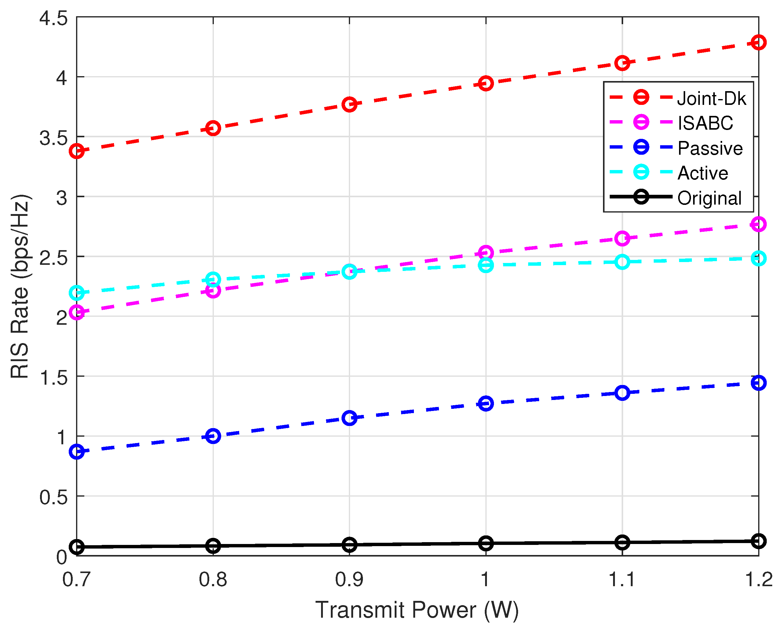
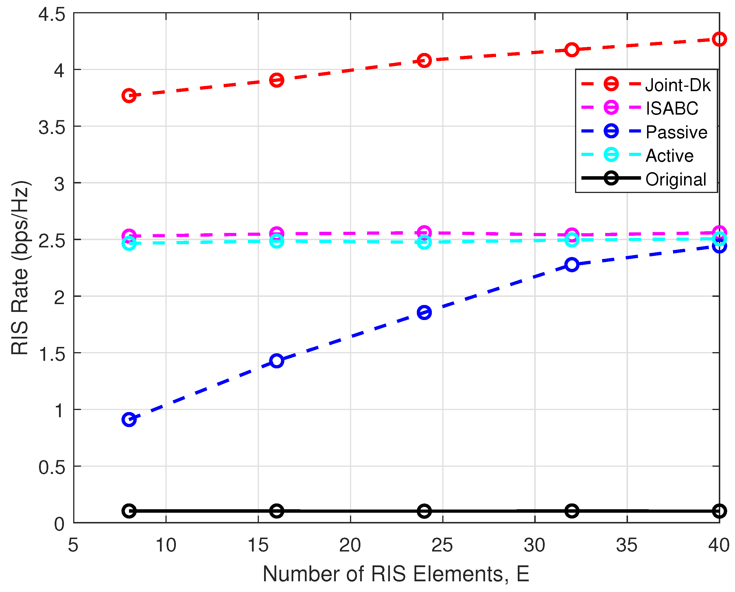
  • Joint-Dk: This legend represents the proposed Dinkelbach scheme to solve the optimization problem in the ISAC-SR system considered with a single user. In Joint-Dk, the transmit beamforming vectors w c ,   w r at the BS and the RIS reflection coefficient v are jointly optimized, as specified in Section 3.
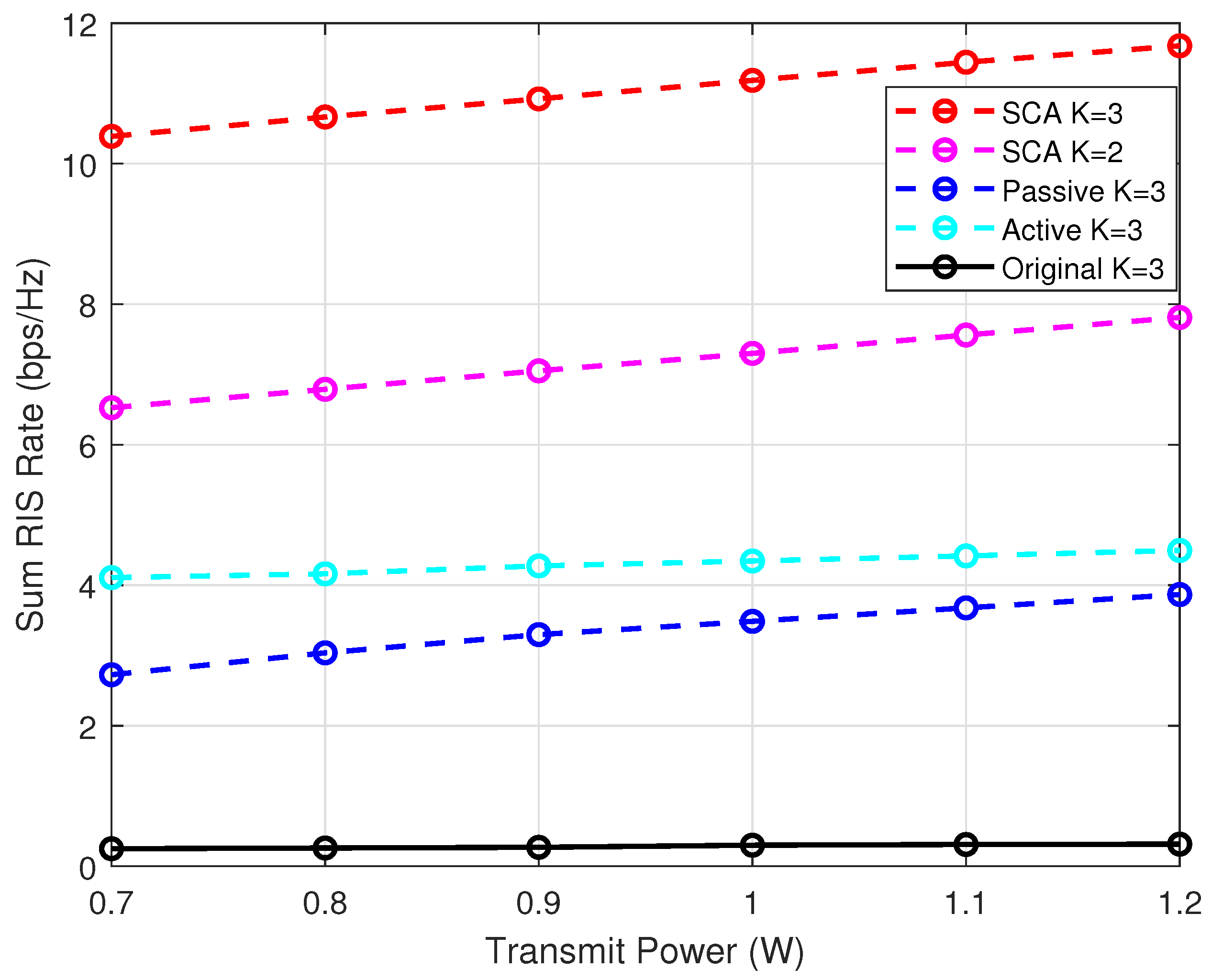
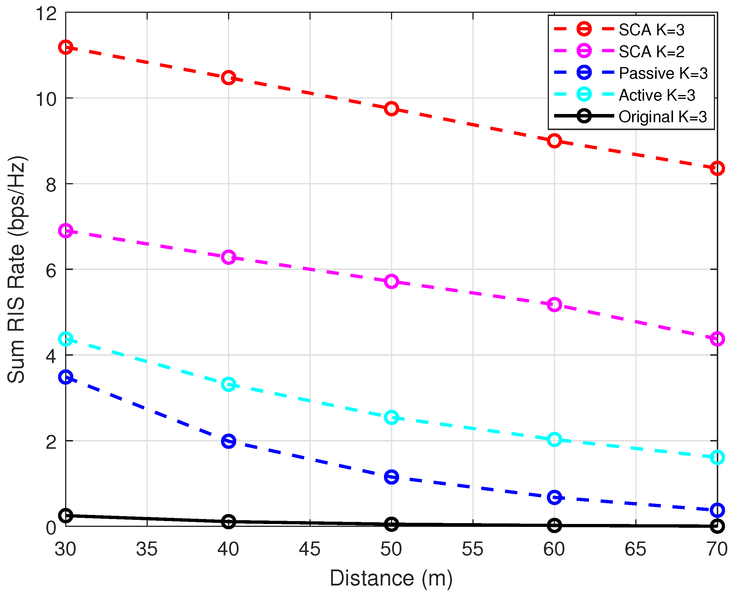
  • Joint-SCA: This legend represents the proposed SCA scheme to solve the optimization problem in the ISAC-SR system considered with multiple users. In Joint-SCA, the transmit beamforming vectors w c ,   w r at the BS and the RIS reflection coefficient v are jointly optimized, as specified in Section 4.
  • ISABC [18]: This legend represents a scheme that is specifically designed for the Integrated Sensing and Backscatter Communication (ISABC) system. In this architecture, the backscatter tag serves as the functional equivalent of the RIS in the SR system. The methodology is restricted to the single-user scenario. To ensure a fair comparative analysis, all critical parameters are maintained at consistent values across experimental configurations.
  • Passive: This legend represents a simplified scheme, where the RIS reflection coefficient v is optimized. The transmit beamforming vectors are, respectively, set as w c = P t M I M , 1 , w r = 0 M , 1 , which ensures the transmit power constraint of the BS.
  • Active: This legend represents a simplified scheme, where the transmit beamforming vectors w c ,   w r at the BS are optimized. The RIS reflection coefficient v is randomly generated.
  • Original: This legend represents a simplified scheme, where the transmit beamforming vectors at the BS are, respectively, set as w c = P t M I M , 1 , w r = 0 M , 1 and the RIS reflection coefficient v is randomly generated.
For the single-user case, Figure 2 shows the communication rate between the RIS and the downlink user with different transmit power under different schemes. It is observed that the RIS rate of the schemes increases with the increasing of the transmit power at the BS. As can be seen, when the transmit power is set as 1.2   W , the proposed “Joint-Dk” scheme achieves a 55 % improvement compared to the “ISABC” scheme, a 73 % improvement compared to the “Active” scheme, a 197 % improvement over the “Passive” scheme and outperforms the “Original” baseline by 35 times. Due to the absence of RIS phase shift optimization, the ISABC benchmark rate is always lower than the proposed “Joint-DK” scheme. The comparison underscores the importance of jointly optimizing the beamforming vectors and the RIS reflection coefficients. Furthermore, the “Active” scheme exhibits a higher rate than the “Passive” scheme, indicating that enhancing the quality of communication through beamforming is a more effective strategy. However, when the beamforming vectors are fixed to optimize the RIS reflection coefficient, the communication rate between the BS and the user is significantly constrained by the limited degrees of freedom at the transmitter.
Subsequently, the RIS rate under different schemes is compared in Figure 3. As we can see, in both the “Joint” and “Passive” schemes, the RIS rate improves with an increasing number of RIS elements. This enhancement arises because the RIS modulates the phase of incident signals through its intelligent elements. A larger number of elements provide higher spatial degrees of freedom, thereby improving communication performance. In contrast, the “ISABC” and “Active” schemes do not benefit from the increasing of the RIS elements, as they do not optimize the reflection coefficients of the RIS.
For the multi-user case, downlink users are distributed within a circle of radius r = 5   m , and d B U = 30   m represents the initial distance between the BS and the center of the circle. Figure 4 illustrates the sum rate between the RIS and multiple downlink users with varying transmit power under different schemes. It is shown that the proposed SCA scheme obtains the best performance in comparison to other benchmark schemes. Furthermore, for different number of users, the sum rate increases as the number of users grows. This trend highlights the scalability of the proposed approach in multi-user scenarios.
Next, we assume that the transmit power and the number of RIS elements are set as P t = 1   W ,   E = 16 , respectively, while the distance from the BS to the user d B U extends from 30   m to 70   m . As shown in Figure 5, the sum rate decreases rapidly with the increasing of d B U . The proposed SCA scheme exhibits the slowest rate decay, which benefits from the joint optimization. Thus, it effectively mitigates path loss and interference. In contrast, the “Active” and “Passive” schemes suffer from rapid performance degradation because of their simplified optimization strategies. When we set d B U = 70   m , the sum rate of the “Passive” scheme approaches zero. This highlights the inherent sensitivity to the distance of the RIS-assisted system. Remarkably, the proposed “Joint-SCA” scheme maintains a certain communication rate, which demonstrates the superiority of the proposed algorithm.
In our ISAC-SR system, the desired beampattern needs to be achieved to guarantee the sensing performance. To show the trade-off between the communication performance and sensing performance, we represent the beampatterns with different beam width in Figure 6. The beam width is adjusted to generate distinct ideal beampatterns, thereby influencing the value of β . The directions of sensing targets are set as θ 1 = 40 ,   θ 2 = 0 ,   θ 3 = 40 . It can be observed that with a smaller beam width, the transmit beampattern is more concentrated towards the direction of targets. As decreases, better communication performance is achieved at the cost of certain sensing performance loss. Moreover, the power radiated towards clutters is low, which can effectively mitigate interference for communications.
Figure 7 compares the convergence of the proposed algorithm with the “Joint-Dk” scheme and the “Joint-SCA” scheme. The stable RIS rate at the end of iterations illustrates the convergence behavior. The “Joint-SCA” scheme converges to a fixed value after six iterations, and the “Joint-DK” scheme converges to a fixed value after seven iterations. This indicates that the former is simpler and more efficient. The convergence rate of the SCA method depends on the selection of the initial point and the precision of the convex approximation. Under identical conditions, the Dinkelbach method achieves a higher communication rate. The SCA method relies on a first-order Taylor approximation of the objective function. By discarding higher-order terms to simplify the process, the SCA method inevitably incurs performance degradation.

6. Conclusions

In this paper, we investigated joint transmit beamforming and RIS phase shifts design for integrated sensing and communication in the RIS-assisted symbiotic radio system. To tackle the formulated non-convex problem, we employed the AO algorithm to iteratively update the value of the objective function. In the single-user case, we utilized the SDR method and Dinkelbach method to transform the non-convex optimization problem into a convex problem. In the multi-user case, we used SCA technology to obtain a suboptimal solution and proved that a rank-one solution is guaranteed. The effectiveness of the proposed design was validated in terms of the communication rate, transmit beampattern and convergence.

Author Contributions

Methodology, Y.W. and X.W.; software, Y.W.; writing—original draft preparation, Y.W.; writing—review and editing, X.W. All authors have read and agreed to the published version of the manuscript.

Funding

This research received no external funding.

Data Availability Statement

The data presented in this study are available upon reasonable request from the corresponding author.

Conflicts of Interest

The authors declare no conflicts of interest.

Abbreviations

The following abbreviations are used in this manuscript:
6GSixth generation
ISACIntegrated sensing and communication
MIMOMultiple-input multiple-output
BSbase station
RISReconfigurable intelligent surface
DFRCDual-function radar communication
SINRSignal-to-noise-plus-interference ratio
SNRSignal-to-noise ratio
OFDMOrthogonal frequency division multiplexing
SRSymbiotic radio
BDBackscatter device
QoSQuality of service
CDMACode division multiple access
TDMATime division multiple access
AOalternating optimization
SCASuccessive convex approximation
SDRSemidefinite relaxation
AWGNAdditive White Gaussian Noise
LoSLine-of-sight
MSEMean square error
SICSuccessive interference cancellation
KKTKarush-Kuhn-Tucker
SDPSemidefinite programming problem

Appendix A

Now we prove Lemma 1. The convex problem (19) satisfies the Slater’s condition. Therefore, the duality gap between the original problem and the dual problem is zero. The optimal upper bound obtained from the Lagrangian function is the supremum. The Lagrangian function of the problem (19) can be expressed as
L ( R , J , λ k , ϕ ) = k = 1 K log ( Tr ( Z k R ) + σ 2 ) a k ( R ( t ) ) Tr ( R R ( t ) ) b k ( R ( t ) ) Tr ( D k R ) + d k + E ( R ) e Tr ( JR )
We have the following definitions:
Z k = D c H Q k H Q k D c + D r H Q k H Q k D r + D r H h k H h k D r
a k ( R ( t ) ) = log ( Tr ( h k H D r R ( t ) D r H h k ) + σ 2 )
b k ( R ( t ) ) = Tr ( h k H D r D r H h k ) ln 2 Tr ( h k H D r R ( t ) D r H h k ) + σ 2
D k = λ k Γ c 1 ( D c H h k h k H D c + D c H Q k H Q k D c ) D r H h k h k H D r D r H Q k H Q k D r
E ( R ) = ϕ L l = 1 L | d ( θ l ) a H ( θ l ) ( D c RD c H + D r RD r H ) a ( θ l ) | 2
d k = λ k σ 2 , e = ϕ β , J 0 , ϕ 0 , λ k 0 ,   k = 1 , , K
where λ k , ϕ , J are the corresponding Lagrange multipliers, respectively; a k ( R ( t ) ) and b k ( R ( t ) ) are functions that depend on the feasible point R ( t ) at the k-th user.
For any optimization problem with strong duality where both the objective function and constraints are differentiable, any pair of primal and dual optimal points must satisfy the Karush-Kuhn-Tucker (KKT) criteria. Therefore, the KKT criteria provide the necessary conditions for the optimal solutions of the problem (A1)
J * 0 , λ k * 0 , ϕ * 0
J * R * = 0
k = 1 K ( Z k Tr ( Z k R * ) + σ 2 b k ( R ( t ) ) I 2 M D k * ) + E ( R * ) J * = 0
where (A8) is due to the non-negativity of the Lagrange multipliers; (A9) corresponds to the complementary slackness condition; (A10) indicates that the gradient at the optimal point is equal to zero. Specifically, (A10) can be transformed to
J * E ( R * ) = k = 1 K ( Z k Tr ( Z k R * ) + σ 2 b k ( R ( t ) ) I 2 M D k * ) C K
As we can see, Rank C K = 2 M . The gradient of E ( R ) at the optimal point has the following expression:
E ( R * ) = 2 ϕ L l = 1 L (   D c H a ( θ l ) a H ( θ l ) D c R * D c H a ( θ l ) a H ( θ l ) D c + D r H a ( θ l ) a H ( θ l ) D r R * D r H a ( θ l ) a H ( θ l ) D r d ( θ l ) D c H a ( θ l ) a H ( θ l ) D c d ( θ l ) D r H a ( θ l ) a H ( θ l ) D r   )
Subsequently, using the fact
Rank ( AB ) min { Rank ( A ) , Rank ( B ) }
Rank ( a ( θ l ) a H ( θ l ) ) = 1
we can get
Rank D c H a ( θ l ) a H ( θ l ) D c = Rank D r H a ( θ l ) a H ( θ l ) D r = 1
Then it can be deduced that
Rank ( E ( R * ) ) = 1
We also have the following inequality:
Rank ( A + B ) Rank ( A ) + Rank ( B )
Thus, (A11) can be written as
Rank ( J * ) + Rank ( E ( R * ) ) Rank ( C K ) = 2 M
As can be observed, one has the following inequality
Rank ( J * ) 2 M 1
Due to the Equation (A9), it can be deduced that Rank ( J * ) = 2 M 1 . Otherwise, we have Rank ( R * ) = 0 , which contradicts the required conditions. Therefore, we have Rank ( R * ) = 1 from the above inference. The proof is completed.

References

  1. Zhang, J.A.; Liu, F.; Masouros, C.; Heath, R.W.; Feng, Z.; Zheng, L.; Petropulu, A. An overview of signal processing techniques for joint communication and radar sensing. IEEE J. Sel. Top. Signal Process. 2021, 15, 1295–1315. [Google Scholar] [CrossRef]
  2. Liu, F.; Masouros, C.; Petropulu, A.P.; Griffiths, H.; Hanzo, L. Joint radar and communication design: Applications, state-of-the-art, and the road ahead. IEEE Trans. Commun. 2020, 68, 3834–3862. [Google Scholar] [CrossRef]
  3. Tan, D.K.P.; He, J.; Li, Y.; Bayesteh, A.; Chen, Y.; Zhu, P.; Tong, W. Integrated sensing and communication in 6G: Motivations, use cases, requirements, challenges and future directions. In Proceedings of the 2021 1st IEEE International Online Symposium on Joint Communications & Sensing (JC&S), Dresden, Germany, 23–24 February 2021; pp. 1–6. [Google Scholar] [CrossRef]
  4. Saruthirathanaworakun, R.; Peha, J.M.; Correia, L.M. Opportunistic sharing between rotating radar and cellular. IEEE J. Sel. Areas Commun. 2012, 30, 1900–1910. [Google Scholar] [CrossRef]
  5. Liu, F.; Masouros, C.; Li, A.; Ratnarajah, T. Robust MIMO beamforming for cellular and radar coexistence. IEEE Wirel. Commun. Lett. 2017, 6, 374–377. [Google Scholar] [CrossRef]
  6. Khawar, A.; Abdelhadi, A.; Clancy, C. Target detection performance of spectrum sharing MIMO radars. IEEE Sens. J. 2015, 15, 4928–4940. [Google Scholar] [CrossRef]
  7. Khawar, A.; Abdelhadi, A.; Clancy, T.C. Coexistence analysis between radar and cellular system in LoS channel. IEEE Antennas Wirel. Propag. Lett. 2015, 15, 972–975. [Google Scholar] [CrossRef]
  8. Liu, F.; Zhou, L.; Masouros, C.; Li, A.; Luo, W.; Petropulu, A. Toward dual-functional radar-communication systems: Optimal waveform design. IEEE Trans. Signal Process. 2018, 66, 4264–4279. [Google Scholar] [CrossRef]
  9. Liu, Y.; Eldar, Y.C. Joint radar-communications strategies for autonomous vehicles. IEEE Signal Process. Mag. 2020, 1053. [Google Scholar] [CrossRef]
  10. Moghaddasi, J.; Wu, K. Multifunctional transceiver for future radar sensing and radio communicating data-fusion platform. IEEE Access 2016, 4, 818–838. [Google Scholar] [CrossRef]
  11. Liu, F.; Masouros, C.; Li, A.; Sun, H.; Hanzo, L. MU-MIMO communications with MIMO radar: From co-existence to joint transmission. IEEE Trans. Wirel. Commun. 2018, 17, 2755–2770. [Google Scholar] [CrossRef]
  12. Liu, X.; Huang, T.; Shlezinger, N.; Liu, Y.; Zhou, J.; Eldar, Y.C. Joint transmit beamforming for multiuser MIMO communications and MIMO radar. IEEE Trans. Signal Process. 2020, 68, 3929–3944. [Google Scholar] [CrossRef]
  13. Leyva, L.; Castanheira, D.; Silva, A.; Gameiro, A. Hybrid Beamforming Design for Communication-Centric ISAC. IEEE Sens. J. 2024, 24, 21179–21190. [Google Scholar] [CrossRef]
  14. Chen, L.; Wang, Z.; Du, Y.; Chen, Y.; Yu, F.R. Generalized transceiver beamforming for DFRC with MIMO radar and MU-MIMO communication. IEEE J. Sel. Areas Commun. 2022, 40, 1795–1808. [Google Scholar] [CrossRef]
  15. Yang, C.; Wang, X.; Ni, W.; Jiang, Y. Optimal Beamforming for MIMO DFRC Systems with Transmit Covariance Constraints. IEEE Trans. Signal Process. 2025, 73, 601–616. [Google Scholar] [CrossRef]
  16. Yang, G.; Liang, Y.C.; Zhang, R.; Pei, Y. Modulation in the air: Backscatter communication over ambient OFDM carrier. IEEE Trans. Commun. 2017, 66, 1219–1233. [Google Scholar] [CrossRef]
  17. Huang, T.; Xu, X.; Kuai, X.; Liang, Y.C.; Zhao, X. Integrated sensing and communication for ambient backscatter communication systems. In Proceedings of the 2022 IEEE 22nd International Conference on Communication Technology (ICCT), Nanjing, China, 11–14 November 2022; pp. 260–265. [Google Scholar] [CrossRef]
  18. Galappaththige, D.; Tellambura, C.; Maaref, A. Integrated sensing and backscatter communication. IEEE Wirel. Commun. Lett. 2023, 12, 2043–2047. [Google Scholar] [CrossRef]
  19. Wang, X.; Fei, Z.; Wu, Q. Integrated sensing and communication for RIS-assisted backscatter systems. IEEE Internet Things J. 2023, 10, 13716–13726. [Google Scholar] [CrossRef]
  20. Long, R.; Liang, Y.C.; Guo, H.; Yang, G.; Zhang, R. Symbiotic radio: A new communication paradigm for passive Internet of Things. IEEE Internet Things J. 2019, 7, 1350–1363. [Google Scholar] [CrossRef]
  21. Han, S.; Liang, Y.C.; Sun, G. The design and optimization of random code assisted multi-BD symbiotic radio system. IEEE Trans. Wirel. Commun. 2021, 20, 5159–5170. [Google Scholar] [CrossRef]
  22. Guo, H.; Liang, Y.C.; Long, R.; Xiao, S.; Zhang, Q. Resource allocation for symbiotic radio system with fading channels. IEEE Access 2019, 7, 34333–34347. [Google Scholar] [CrossRef]
  23. Yang, H.; Ye, Y.; Liang, K.; Chu, X. Energy efficiency maximization for symbiotic radio networks with multiple backscatter devices. IEEE Open J. Commun. Soc. 2021, 2, 1431–1444. [Google Scholar] [CrossRef]
  24. Chu, Z.; Hao, W.; Xiao, P.; Khalily, M.; Tafazolli, R. Resource allocations for symbiotic radio with finite blocklength backscatter link. IEEE Internet Things J. 2020, 7, 8192–8207. [Google Scholar] [CrossRef]
  25. Long, R.; Guo, H.; Zhang, L.; Liang, Y.C. Full-duplex backscatter communications in symbiotic radio systems. IEEE Access 2019, 7, 21597–21608. [Google Scholar] [CrossRef]
  26. Zhang, Q.; Liang, Y.C.; Poor, H.V. Reconfigurable intelligent surface assisted MIMO symbiotic radio networks. IEEE Trans. Commun. 2021, 69, 4832–4846. [Google Scholar] [CrossRef]
  27. Chen, H.; Yang, G.; Liang, Y.C. Joint active and passive beamforming for reconfigurable intelligent surface enhanced symbiotic radio system. IEEE Wirel. Commun. Lett. 2021, 10, 1056–1060. [Google Scholar] [CrossRef]
  28. Xu, X.; Liang, Y.C.; Yang, G.; Zhao, L. Reconfigurable Intelligent Surface Empowered Symbiotic Radio Over Broadcasting Signals. IEEE Trans. Commun. 2021, 69, 7003–7016. [Google Scholar] [CrossRef]
  29. Hakimi, A.; Zargari, S.; Tellambura, C. Integrated Sensing and Communication With Symbiotic Radio and RIS-Assisted Backscatter. IEEE Wirel. Commun. Lett. 2025, 14, 38–42. [Google Scholar] [CrossRef]
  30. Dinkelbach, W. On nonlinear fractional programming. Manag. Sci. 1967, 13, 492–498. [Google Scholar] [CrossRef]
  31. Grant, M.; Boyd, S. CVX: Matlab Software for Disciplined Convex Programming, Version 2.2. 2020. Available online: https://cvxr.com/cvx/ (accessed on 13 May 2025).
  32. Sidiropoulos, N.D.; Davidson, T.N.; Luo, Z.Q. Transmit beamforming for physical-layer multicasting. IEEE Trans. Signal Process. 2006, 54, 2239–2251. [Google Scholar] [CrossRef]
  33. Hakimi, A.; Zargari, S.; Tellambura, C.; Herath, S. Sum rate maximization of MIMO monostatic backscatter networks by suppressing residual self-interference. IEEE Trans. Commun. 2022, 71, 512–526. [Google Scholar] [CrossRef]
  34. Fuhrmann, D.R.; San Antonio, G. Transmit beamforming for MIMO radar systems using signal cross-correlation. IEEE Trans. Aerosp. Electron. Syst. 2008, 44, 171–186. [Google Scholar] [CrossRef]
Figure 1. ISAC-SR system with K users.
Electronics 14 02016 g001
Figure 2. RIS rate versus transmit power at the BS under different schemes.
Electronics 14 02016 g002
Figure 3. RIS rate versus number of RIS elements under different schemes.
Electronics 14 02016 g003
Figure 4. Sum RIS rate versus transmit power at the BS in the multi-user case.
Electronics 14 02016 g004
Figure 5. Sum RIS rate versus distance from the BS to users in the multi-user case.
Electronics 14 02016 g005
Figure 6. Transmit beampattern with different beam width.
Electronics 14 02016 g006
Figure 7. Convergence behavior of Algorithms 1 and 2.
Electronics 14 02016 g007
Disclaimer/Publisher’s Note: The statements, opinions and data contained in all publications are solely those of the individual author(s) and contributor(s) and not of MDPI and/or the editor(s). MDPI and/or the editor(s) disclaim responsibility for any injury to people or property resulting from any ideas, methods, instructions or products referred to in the content.

