1. Introduction
The rapid development of terahertz (THz) technology has gradually found applications in high-efficiency communication, imaging, and sensing fields, demonstrating tremendous potential in the design of identification tags [
1,
2,
3,
4]. The THz frequency band offers abundant spectral resources, high transmission rates, and wide bandwidth advantages, making it an ideal candidate technology for future efficient and precise communication and positioning systems [
5,
6]. Traditional RFID systems, when operating in the microwave and millimeter-wave frequency bands, are prone to interference from the environment, obstacles, and metal reflections, resulting in reduced identification rates [
7,
8,
9]. THz technology can achieve high-resolution identification and positioning over very short distances [
10]. A key challenge currently is how to improve the positioning accuracy and identification capability of THz RFID tags in complex indoor electromagnetic environments [
11].
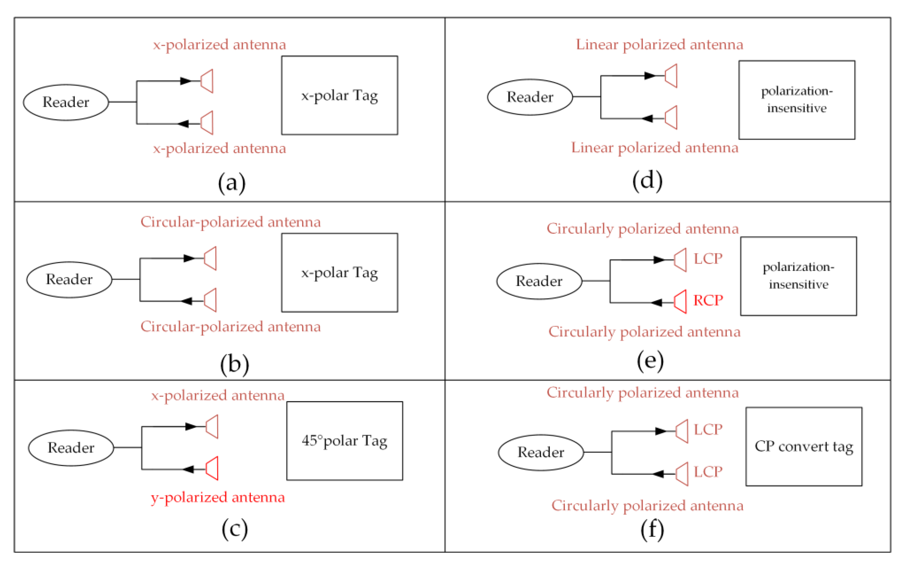
In the face of complex electromagnetic environments, altering the polarization characteristics of the tag can effectively reduce environmental impacts. Linear cross-polarized RFID tags have the ability to convert incident linearly polarized waves into cross-polarized ones. Rotating a linearly polarized tag by 45° achieves orthogonal reflection of the linearly polarized wave [
12,
13]. The incident linearly polarized wave is reflected in a cross-polarized form, thereby isolating the reflected signal from the metal reflection waves’ polarization and reducing the impact of metal environments [
14,
15]. As shown in
Figure 1c, this design requires the polarization direction of the incident wave to form a 45° angle with the tag. When the tag antenna and reader antenna rotate relative to each other, the polarization conversion capability is affected. Polarization-independent RFID tags make the reflected wave’s polarization characteristics consistent with the incident wave’s polarization characteristics, which occurs when a tag’s rotational symmetry angle is less than 90° [
16]. A polarization-insensitive RFID tag antenna with a rotational symmetry angle of 60° is insensitive to both pitch and rotation angles, providing stable reflection characteristics and thus enhancing the tag’s identification capability, as shown in
Figure 1d.
Circular polarization, due to its advantage in resisting multipath effects, can significantly enhance the stability of the system [
17]. Circular polarization cross-polarization scattering technology has been proposed in recent years. Unlike linear polarization, circularly polarized waves undergo polarization conversion after metal reflection. Therefore, when the tag’s reflected wave and the incident wave share the same polarization, there is a high level of polarization isolation between the reflected wave and the background scattering wave, as shown in
Figure 1f. The circular polarization co-polarized reflection RFID tag, a novel tag proposed in 2020 [
18], can be regarded as an application of the circular polarization geometric phase characteristics. This design not only possesses the advantages of co-polarized tags but also eliminates the need for prior calibration. The ground plane method can realize circular polarization co-polarized RFID tags, and in 2022, Etienne Perret and others loaded a ground plane onto the RFID tag [
19]. The reflection of the ground plane ensures that the dipole structure satisfies the 180° phase difference between the two polarizations, and by rotating the dipole elements of different sizes, stable reflection after polarization conversion of circular polarization is achieved. This realizes a depolarized tag, where 360° rotation does not affect detection performance. In 2024, we proposed an independent dual-circularly polarized chipless RFID tag used for measuring the incident angle between the RFID tag and the reader [
20].
This paper presents a novel tag that utilizes a circular polarization encoding method. The design demonstrates enhanced stability in metal environments, effectively mitigating signal disturbances caused by surface reflections and exhibiting robust anti-interference capabilities. It provides an innovative design approach and technical solution for the implementation of THz identification tags in complex and challenging environments. The tag shows promise for use in indoor positioning systems, allowing for precise localization in environments with high levels of electromagnetic interference. Additionally, the robustness of the encoding mechanism against environmental disturbances makes it suitable for object identification applications, such as distinguishing goods or assets in warehouses or metal-laden industrial settings. The circular polarization encoding method can serve as a complementary approach to traditional encoding techniques, effectively expanding the encoding range and enhancing the flexibility and robustness of encoding systems.
2. Independent Dual Circularly Polarization Design Mechanism
The tag achieves polarization encoding functionality through the design of geometric phase elements. These geometric phase elements exhibit polarization conversion and associated opposite circularly phase shift characteristics. The geometric phase characteristics are expressed by the scattering matrix. The scattering matrix of arbitrary polarization element is
M1 in Equation (1). The polarization conversion of the geometric phase element is facilitated by the orthogonal linear polarization components, wherein a 180° phase difference. The scattering matrix corresponding to the geometric phase element is presented in Equation (2) [
21]. Specifically, when LCP waves ([1,−j] -
z-axis) are incident, the reflected wave remains LCP ([1,j] +
z-axis) (express as LCP-LCP), and when RCP waves ([1,j] -
z-axis) are incident, the reflected wave remains RCP ([1,−j] +
z-axis) (express as RCP-RCP).
where
rxx represents
x-polarized transmission for
x-polarized incidence;
rxy represents
x-polarized transmission for
y-polarized incidence;
ryx represents
y-polarized transmission for
x-polarized incidence;
ryy represents
y-polarized transmission for
y-polarized incidence.
During the rotation of the geometric phase element, an opposite phase shift is observed between LCP–LCP and RCP–RCP components. The scattering matrix of the geometric phase element, parameterized by a rotation angle
θ, is presented in Equation (3). When the rotation angle is set to
θ1 = 45°,
φ =
φ0, the corresponding scattering matrix is shown in Equation (4). Under these conditions, the phase shift for LCP-LCP is
φ0 + 90°, while the phase shift for RCP-RCP is
φ0–90°. Which have reversed geometric phase shift.
By adjusting the structural dimensions, a dynamic phase shift
φ =
φ0 + 90° can be realized, and its scattering matrix is depicted in Equation (5).
When two elements with a 90° dynamic phase difference and a 45° rotational angle difference are combined into an array, if the rotation angle is clockwise (
θ1 = 45°), the tag will not reflect under LCP–LCP but will reflect RCP–RCP (01), as shown in Equations (6) and (7). When the element is rotated counterclockwise (
θ1 = –45°), LCP–LCP is normally reflected, while RCP–RCP results in no reflection (10), as shown in Equations (8) and (9). The energy will be scattered in other directions rather than being absorbed by the tag. This approach enables the realization of 2-bit polarization encoding.
3. Dual Circularly Polarized Element Design
Two geometric phase elements with different structures were designed. The structures of the two elements are shown in
Figure 2. Both elements consist of a patch layer, a quartz dielectric layer, and a metal ground layer with the same thickness. The patch layer is composed of two semi-ellipses linked by a strip line. The linked-semi-ellipses in Element 1 are separated along the major axis, while those in Element 2 are separated along the minor axis. The major and minor axes of Element 1 are
a1 and
b1, respectively, and those of Element 2 are
a2 and
b2. The geometric phase of the elements is altered by rotation, with the rotation angles
θ1 and
θ2, respectively. The dynamic phase shift of the elements is adjusted by modifying the dimensions of the major and minor axes, ensuring that the geometric phase difference of the two elements remains at 90°. Additionally, dispersion is controlled by adjusting parameters
d1 and
d2, enabling the two elements to maintain a stable 90° phase difference over a relatively broad bandwidth. The dimensions of the element structures are shown in
Table 1. The linked-semi-ellipses of Element 1 are arranged horizontally, while those of Element 2 are positioned vertically. According to Equation (2), a 90° rotation leads to a 180° in the reflection phase, which results in a 360° phase difference between the two elements. Consequently, the 90° rotation of the element does not influence the phase difference.
The reflection responses of the proposed elements were simulated using the Floquet mode in CST Studio Suite to conduct a comprehensive full-wave electromagnetic analysis. The simulated results, illustrated in
Figure 3, detail the reflection characteristics under the illumination of an LCP wave. For Element 1, the reflection coefficient for LCP-LCP remains consistently below −1 dB over the frequency range of 0.34–0.53 THz. Similarly, for Element 2, the reflection coefficient remains below −1 dB across the range of 0.42–0.60 THz. Therefore, both tags demonstrate a polarization conversion rate exceeding 80%, particularly within the overlapping frequency range of 0.42–0.53 THz. Given that the reflection coefficient characteristics for RCP waves are theoretically symmetric to those of LCP waves, the corresponding simulation results for RCP incidence are omitted for brevity.
When the rotation angles of the two elements are set to 0° (
θ1 = 0°,
θ2 = 0°), we compared the simulated reflection phases of the LCP-LCP, as shown in
Figure 4. The results display the phase difference between Element 1 and Element 2. Due to structural variations, a dynamic phase difference arises between the two elements. Within the frequency range of 0.42–0.53 THz, this dynamic phase difference remains consistently stable at 90°, with a phase error magnitude of less than 2°.
The primary challenge in the design of the elements lies in achieving both manufacturability and broadband performance while ensuring that the two elements simultaneously exhibit geometric phase shifts with a 90° phase difference across a relatively wide bandwidth.
The regulation of the semi-ellipse element’s major and minor axes is effective in tuning the operating bandwidth and relative phase of the elements. The simulation results of amplitude performance for Element 1 under varying major and minor axes are shown in
Figure 5. With an increase in
a1 (major axis) and
b1 (minor axis), the operating bandwidth of the element shifts toward lower frequencies. The simulation results of phase performance under the same conditions are illustrated in
Figure 6. Changes in parameter
a1 (major axis) have a significant effect on the phase of the element, whereas parameter
b1 (minor axis) has minimal impact on the phase.
The simulation results of amplitude performance for Element 2 under varying major and minor axes are shown in
Figure 7. Similarly, with an increase in
a1 (major axis) and
b1 (minor axis), the operating bandwidth of the element shifts toward lower frequencies. The simulation results of phase performance under the same conditions are illustrated in
Figure 8. Changes in parameter
a1 (major axis) have a minimal effect on the phase of the element, whereas parameter
b1 (minor axis) has a significant impact on the phase.
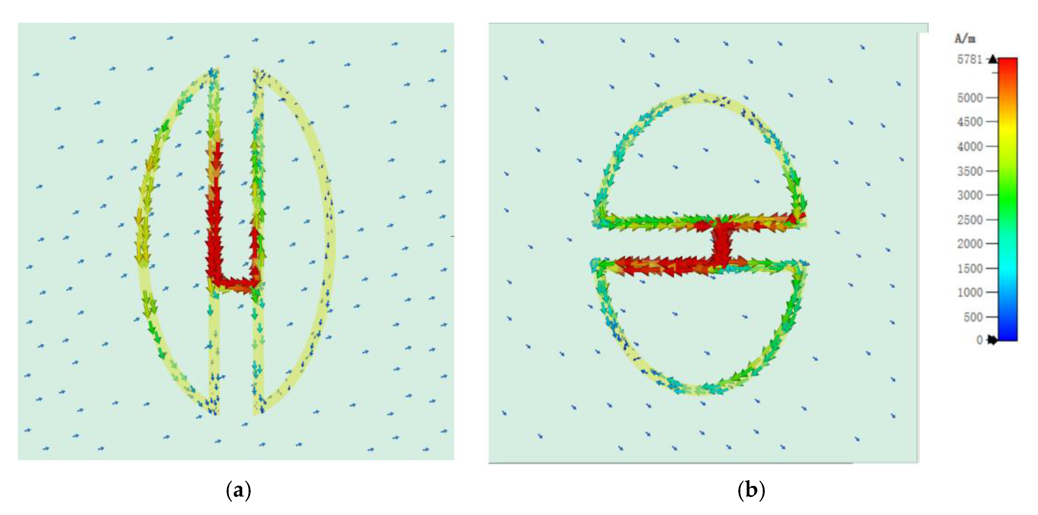
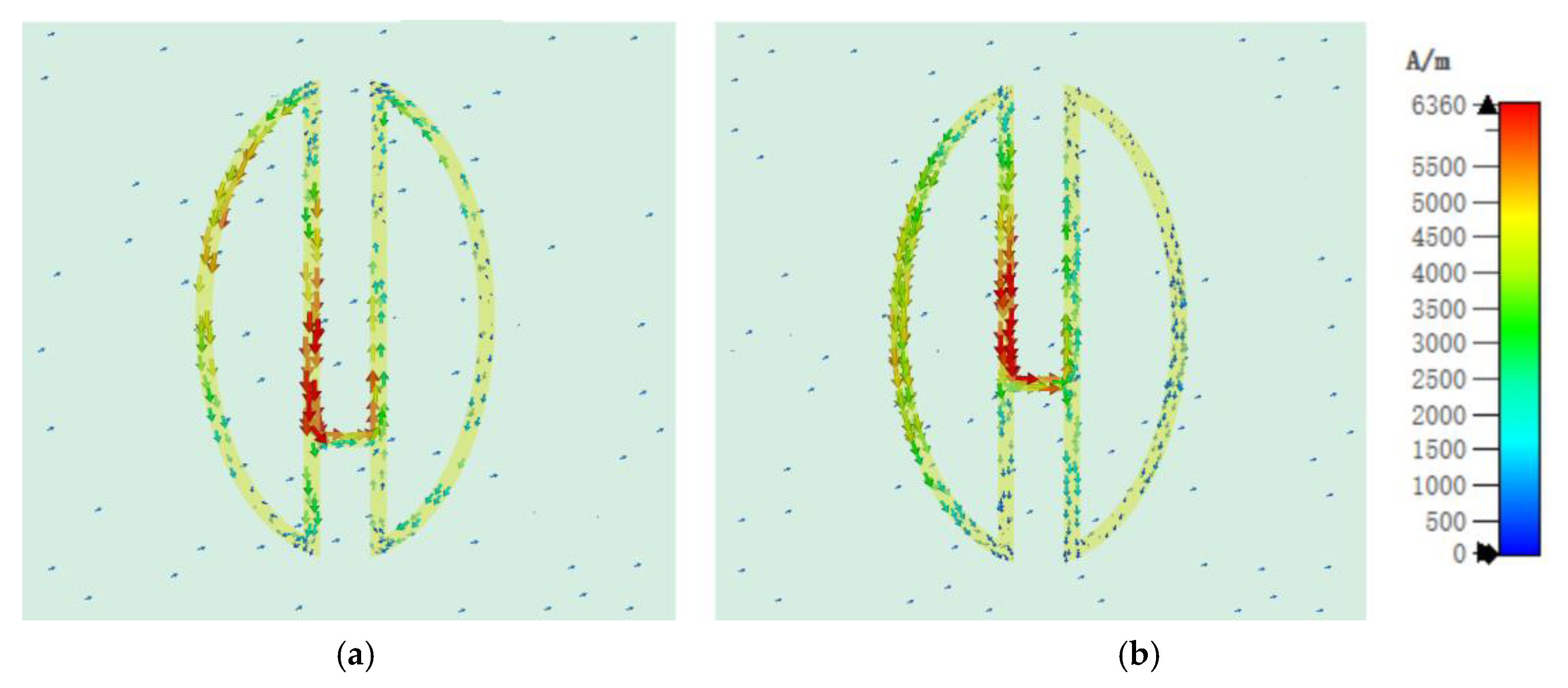
The performance characteristics of the simulated element were validated by analyzing its surface current behavior. The LCP wave was used to illustrate the element, with the surface current phases of the two elements adjusted to achieve their instantaneous maximum values, as illustrated in
Figure 9. For Element 1, the surface current phase was set to 225°, while for Element 2, it was 270°, resulting in a 45° phase difference. Under identical simulation conditions, this 45° surface current phase difference produced a 90° reflection phase difference, attributable to the intrinsic properties of the structure.
By analyzing the current distribution, we explored the dispersion characteristics of the two elements. The differing orientations of the ellipses between Element 1 and Element 2 result in notable differences in the lengths of the straight-line regions within their semi-ellipses. The surface current of Element 1 with different
d1 dimensions is shown in
Figure 10. Adjusting the position of connection line
d1 causes the primary current distribution of Element 1 to concentrate in the straight-line region, with minimal variation across a specific frequency range. The surface current of Element 2 with different
d2 dimensions is shown in
Figure 11. In contrast, altering the length of
d2 in Element 2 induces significant variations in its current distribution. The current distribution between the elliptical and straight-line regions shifts markedly across frequencies, leading to more pronounced dispersion changes in Element 2. By fine-tuning the dimensions of
d1 and
d2, precise control over the dispersion characteristics and phase shift of the elements can be achieved
d1 and
d2.
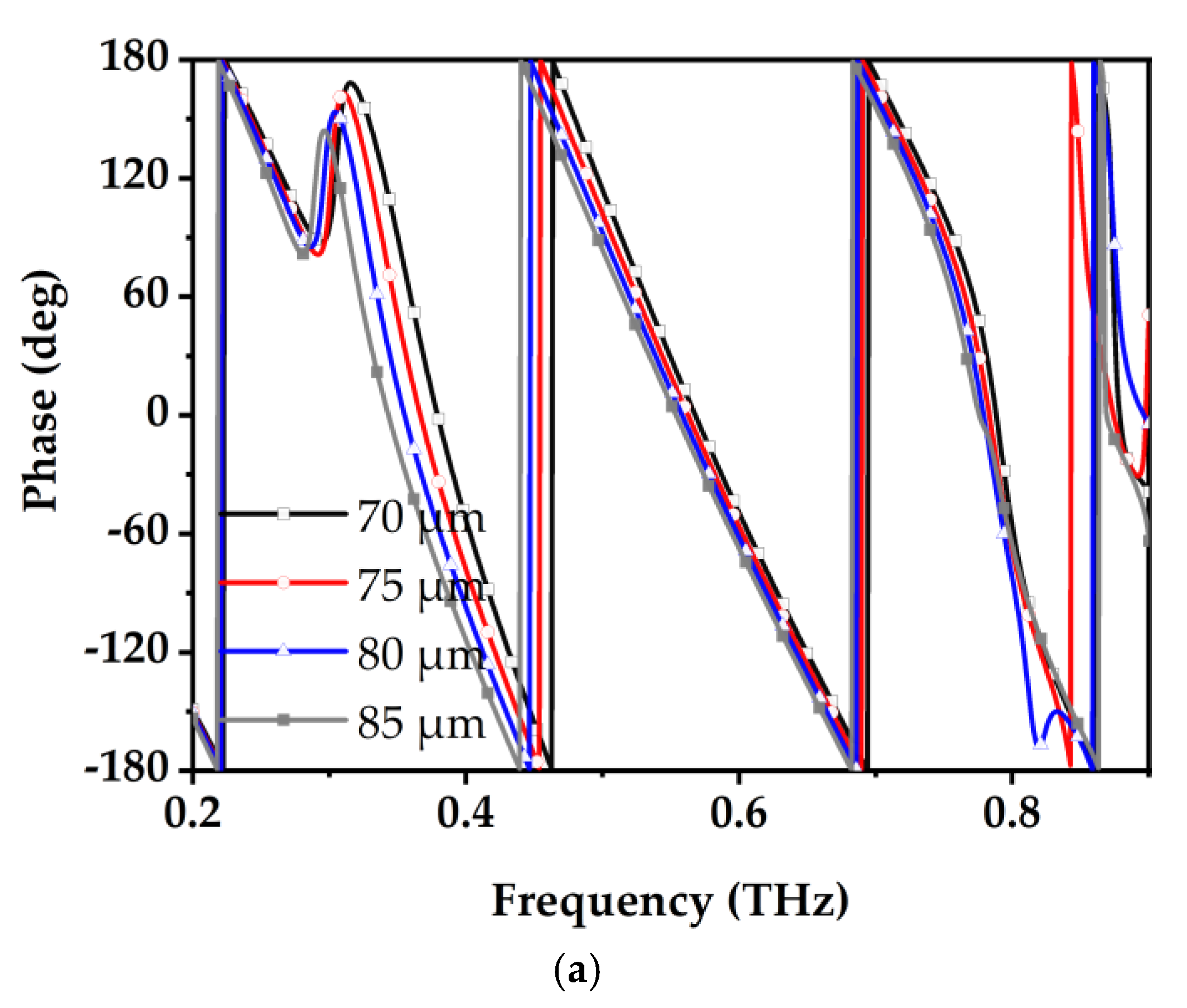
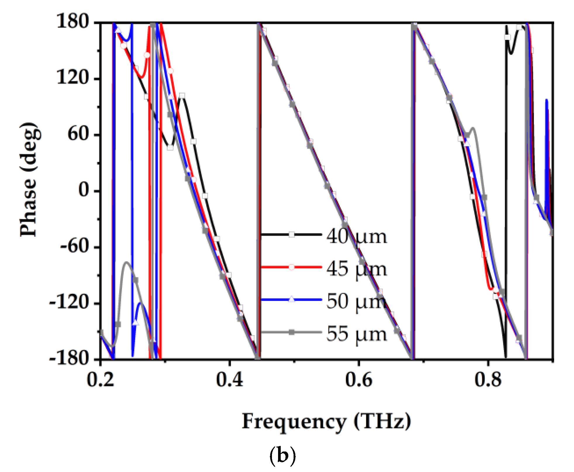
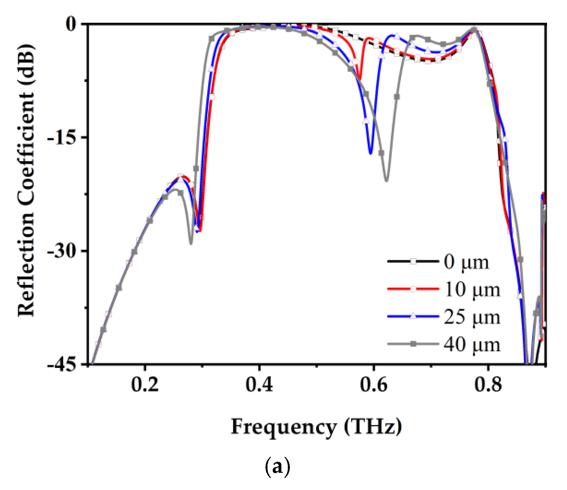
Simulations were performed to examine the influence of
d1 and
d2 on the elements’ phase and dispersion characteristics. The simulation results for varying the size of
d1 in Element 1 are shown in
Figure 12a. As
d1 increases, the dispersion variation within the operational frequency range remains minimal, while the relative phase change becomes more pronounced. At 0.45 THz, the phase variation with
d1 is approximately 0.5°/μm, while the dispersion variation with
d1 is about −2.2°/(THz μm). Conversely, as shown in
Figure 12b, the simulation results for varying
d2 in Element 2 reveal significant changes in dispersion characteristics. At 0.45 THz, the phase variation with
d2 is approximately 0.8°/μm, while the desperation variation with
d2 is −6.1°/(THz μm). Precisely controlling the relative phase between the two elements could be achieved by fine-tuning
d1 and
d2. The adjustment process involves modifying
d2 to align the dispersion characteristics of Element 1 and Element 2. Subsequently,
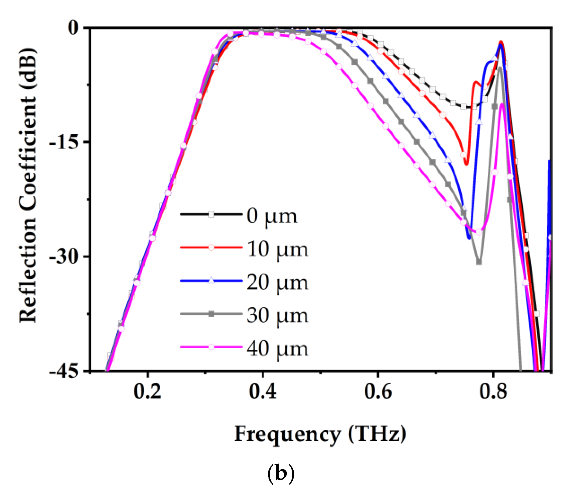
d1 is adjusted to maintain a phase difference of 90° between the two elements. The amplitude simulation results for varying
d1 and
d2 are also depicted in
Figure 13. It is evident that as
d1 and
d2 increase, the polarization conversion rate of the elements decreases at higher frequencies, resulting in a minor reduction in operational bandwidth.
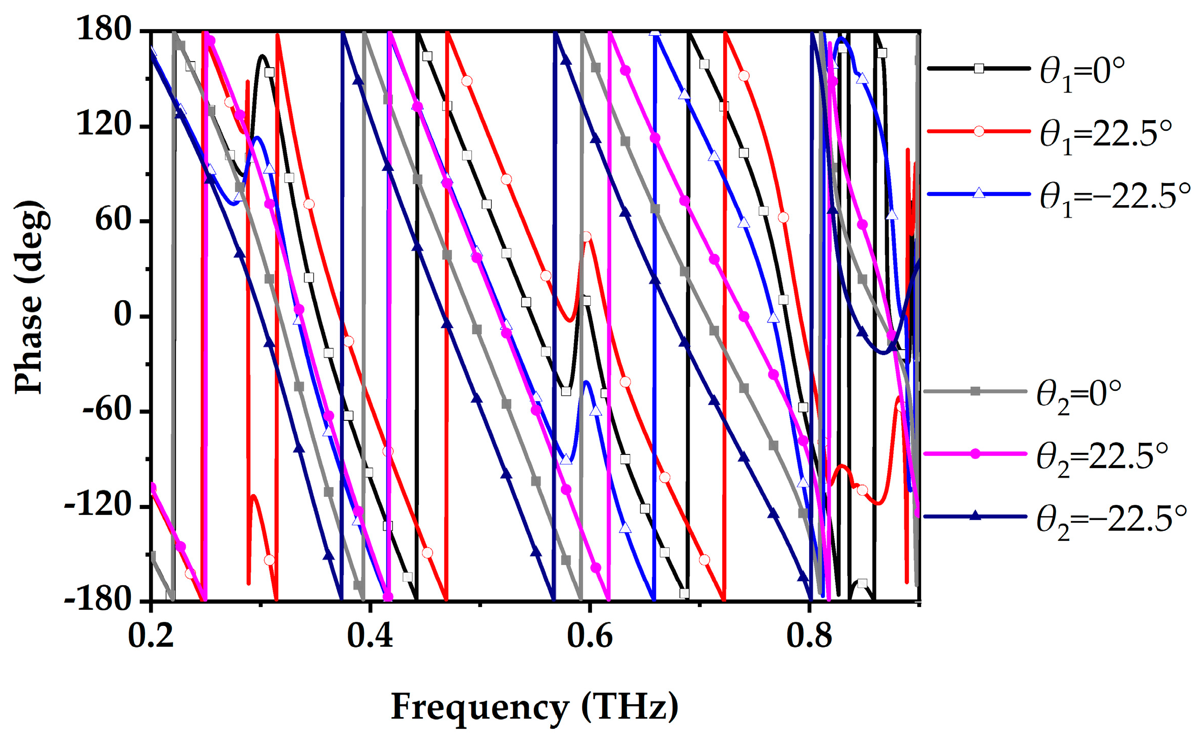
The rotation of dynamic phase elements induces geometric phase shifts. When Element 1 and Element 2 are rotated by 22.5° and −22.5°, respectively,
Figure 14 illustrates the variation in reflection phases for LCP-LCP. When Element 1 is rotated by
θ1 = −22.5° and Element 2 by
θ2 = 22.5°, the phases of the two elements become identical, and their dispersion characteristics are nearly indistinguishable. In contrast, when Element 1 is rotated by
θ1= 22.5° and Element 2 by
θ2 = −22.5°, their phases exhibit a consistent 180° difference across a relatively wide bandwidth. For RCP-RCP, the simulated reflection phases are also presented in
Figure 15. The rotational effects of the elements are reversed compared to those observed under LCP conditions. Owing to the non-dispersive nature of geometric phase shifts, the phase relationships outlined above remain consistent across the entire operational frequency band. The inherent stability of geometric phase shifts across a broad operational bandwidth ensures reliable phase relationships, making this approach well-suited for advanced electromagnetic applications.
By integrating the amplitude, geometric phase, and dynamic phase, we identified the element’s working bandwidth as 0.42–0.52 THz, with a relative bandwidth of 21.2%. Across this range, the polarization conversion rate (PCR)—the ratio of energy reflected in the intended circular polarization state to the input energy of that polarization—for both Element 1 and Element 2 consistently exceeds 80%, while the dynamic phase difference remains inherently stable at 90°. Under circularly polarized incident waves, both elements demonstrate geometric phase characteristics. The comparison of the THz polarization convert element with recent works is shown in
Table 2. The proposed element with wide band independent dual circularly polarized properties, which is available for THz identification tag design.
The reflection phase of Element 1, under conditions of
θ1 = 0°, was normalized to zero, with the phase comparison results at 0.45 THz presented in
Table 3.
4. Identification Tag Design
The identification tag developed in this study employs a 2-bit circular polarization encoding technique with polarization conversion capability. Its encoding mechanism is based on the sum-and-difference beam theory. In scenarios where all elements have identical reflection phases
, the element reflection vectors align and add constructively in the same direction, resulting in the maximum reflected intensity
. Conversely, by adjusting the reflection phases to ensure the vectors cancel each other out, the reflected intensity
is minimized. By precisely controlling the phase distribution of the tag’s structural elements, a significant difference in the reflected amplitude is generated under LCP and RCP wave incidence, thereby establishing the circular polarization encoding states ‘0’ and ‘1’.
where
is the element’s reflection amplitude,
is the element’s reflection phase shift.
Figure 16 illustrates the phase distribution configuration required for the tag to display the sum-and-difference beam characteristics.
The coding tag is shown in
Figure 17. The tag employs proposed linked-semi-ellipses elements, with design parameters including a ±22.5° element rotation angle configuration. The structure leverages phase modulation induced by geometric rotation to achieve three distinct encoding modes: (1) the tag element reflects an amplitude of ‘0’ under LCP wave illustrated and ‘1’ under RCP wave illustrated (LCP-0/RCP-1); (2) a complementary encoding mode, where LCP reflection has an amplitude of ‘1’ and RCP has ‘0’ (LCP-1/RCP-0); and (3) a cross-polarization enhancement effect, where both polarization waves act synergistically to form a fully activated ‘1–1’ encoding state.
The radar cross section (RCS) pattern simulation results for tag (10) at 0.45 THz are shown in
Figure 18. Under LCP incidence, the reflected energy is nearly entirely LCP, with the maximum scattering value at 0° being LCP-LCP RCS −49.9 dB·m
2, a polarization conversion efficiency of 86.9%, and a 3 dB beamwidth of ±22°. Under RCP incidence, the reflected energy is predominantly scattered in the 50° direction, with an RCP-RCP RCS of −66.3 dB·m
2 at 0° and a polarization conversion efficiency of 14.6%. The polarization conversion efficiency of the tag is influenced by both the element’s polarization conversion efficiency and the direct metal reflection. For RCP–RCP, the element’s polarization conversion efficiency is low, and the primary influencing factor is the coupling between the elements. The RCS radiation pattern simulation for tag (01) at 0.45 THz is shown in
Figure 19. The simulation characteristics are symmetric to those of tag (10), with an error of less than 0.2 dB. The comparison of the four encoding tag reflection patterns is shown in
Figure 20.
The reflected RCS frequency band of the tags under four encoding states (00, 01, 10, 11) was simulated. Encoding states (00) and (11) are shown in
Figure 21. For the (00) state, the LCP-LCP reflected RCS remains below –115 dB. In contrast, for the (11) state, a significant polarization conversion occurs in the 0.41–0.54 THz frequency band, where the LCP-LCP reflected RCS exceeds –51.7 dB·m
2, and the polarization conversion rate is greater than 80%. Under RCP incidence, the simulation results for state (11) are essentially identical to those under LCP incidence.
For states (10) and (01), symmetrical distributions are observed, as shown in
Figure 22. In the 0.41–0.53 THz range (relative bandwidth 23.6%), the co-polarized reflection RCS exceeds –51.6 dB·m
2, and the difference-beam co-polarized RCS is below –61.1 dB·m
2. The cross-polarized reflection for both beams remains below –55.7 dB·m
2. The primary source of mutual interference among different tags is their cross-polarized reflections. Within this frequency range, the signal-to-interference ratio (SIR) is below 4.1 dB, while at 0.45 THz, the minimum SIR can reach 8.1 dB. The comparison of the four encoding tag reflections is shown in
Figure 23.
Overall, in the terahertz band, the influence of the surrounding environment is relatively small, allowing the tag to maintain a high SIR level and thereby ensuring excellent performance.
Finally, the advantages of the proposed THz identification tag compared to other chipless THz identification tags and polarization convert tag designs are shown in
Table 4. Unlike multi-layer or complex 3D structures, the proposed tag features a single-layer structure with CP conversion capability, ensuring simplicity and efficiency. While its encoding capacity of 4 tags is more modest compared to some designs, such as the 32-tag capacity of the OAM-based 3D structure, it achieves robust polarization conversion functionality and operates at 0.45 THz, making it highly suitable for applications in compact and complex environments. This positions the proposed design as a balanced solution combining simplicity, CP conversion capability, and practical encoding capacity. The promising simulation results demonstrate effective polarization conversion. We plan to employ photolithography techniques to construct prototypes for testing, further enhancing the practical relevance and applicability of our study.


