Article

Energy Storage Converter Off-Grid Parallel Cooperative Control Based on CAN Bus

1
Institute of Automation, Qilu University of Technology (Shandong Academy of Sciences), Jinan 250000, China
2
Qingdao Veccon Electric Co., Ltd., Qingdao 266200, China
*
Author to whom correspondence should be addressed.
Electronics 2025, 14(10), 2010; https://doi.org/10.3390/electronics14102010
Submission received: 15 April 2025 / Revised: 12 May 2025 / Accepted: 13 May 2025 / Published: 15 May 2025

Abstract

:
With the rapid development of the industrial sector, the single-inverter power device is increasingly unable to meet the industry’s high-power needs due to the power limitations of semiconductor devices; as a result, parallel connection of multiple devices has become the main means of expanding the capacity of power conversion systems. To address the issues of circulating current and power imbalance caused by discrepancies in the output voltage amplitude and phase among power conversion system (PCS) modules, this paper proposes a master–slave mode-based collaborative control method for energy storage inverters operating in parallel—the method consists of two main components: phase synchronization control and equal amplitude control. The master sends the synchronization signal and voltage amplitude to the slave inverters via the CAN bus, and each slave then adjusts its phase based on the synchronization signal and calculates the modulation ratio of the wave according to their own power supply conditions. This ensures that the output voltage amplitude, phase, and frequency of all slave inverters are fully aligned. Experimental results validate the effectiveness of the proposed parallel coordinated control method, ensuring the stable operation of the parallel system.

1. Introduction

Building a new power system centered on renewable energy is a key initiative to promote green energy transformation, ensure energy security, and accelerate the realization of the dual carbon goal [1]. In coal mines, traditional diesel power generation systems used as emergency power supplies suffer from several limitations, including poor responsiveness to impact loads, high routine maintenance costs, and unreliable start-up performance. These shortcomings make it difficult to meet critical load demands, such as the stringent response time required by main ventilation fans. Energy storage inverters, represented by lithium iron phosphate batteries, can perfectly solve the aforementioned challenges. Compared with other battery types, lithium iron phosphate batteries have higher energy density and longer service life [2,3]. While ensuring the primary tasks of powering mine hoists, main fan ventilation, and underground emergency drainage during outages, the remaining energy can be used for peak shaving and valley filling operations based on the principle of economic maximization. This not only serves as a robust safety backup for underground personnel but also enhances the economic efficiency of coal mine energy consumption. With the growing number of electrical loads, energy storage converters are now expected to meet higher standards in terms of capacity, reliability, and safety. However, the power output of a single inverter is constrained by the limitations of semiconductor devices, such as IGBT or SiC modules, which restrict the current and voltage ratings. Designing ultra-high-capacity single-inverter systems is not only technologically challenging but also cost prohibitive. Moreover, single-inverter systems suffer from complex thermal management requirements and efficiency loss due to bulky cooling solutions and higher switching losses. Their centralized nature also results in lower system reliability, as a failure in the single inverter can lead to complete system shutdown and power interruption. In contrast, the parallel operation of multiple inverters enables flexible system capacity expansion and improved fault tolerance. This modular approach distributes thermal loads more evenly and enhances overall reliability, making it a key trend in the advancement of energy storage technology [4,5,6,7].
At present, the parallel connection of energy storage converters has been widely studied by scholars at home and abroad. Distributed large-capacity energy storage systems use multiple low-voltage power conversion system units operated in parallel through an AC bus. Compared to series connections, parallel connections are more challenging because they require the synchronization of all components as a prerequisite to restrain circulating current and improve the overall efficiency and stability of the system [8,9,10]. The topology and control strategy of energy storage converters are summarized and analyzed in [11]. The literature in [12] proposed a centralized acquisition + centralized control scheme based on FPGA. Each controller has a common triangular carrier, combined with the modulation wave compensation scheme proposed by the software, which ensures the simultaneity of module data acquisition, transmission, and output; reduces the difference of drive pulses; and suppresses zero-sequence circulation. In [13], a global synchronous pulse width modulation carrier synchronization (PLL-CS) method based on the phase-locked loop is proposed. This method can realize the effective synchronization of the switching sequence without using the low-delay synchronization signal, which improves the operational reliability of the system. In [14], the droop control strategy is improved by adding a virtual impedance link to the control loop of the converter, and the power balance and stable operation between parallel converters are realized. A localized master–slave coordinated control strategy based on virtual impedance technology is proposed in [15]. The improved droop control is used to achieve synchronization and power consistency between the micro-source strings, while the remaining series micro-sources locally follow the master controller to achieve global power sharing. However, the droop mode also has some disadvantages. When the load suddenly increases or decreases, the voltage and frequency are instantly reduced or increased, which is not conducive to the stable operation of the system [16,17,18]. The literature in [19] proposed a control strategy based on the coordinated operation of the energy storage converter and the photovoltaic inverter, so that the photovoltaic system and the energy storage system can respond to the load change in the network at the same time, so as to achieve the purpose of suppressing the transient power fluctuation of the energy storage converter. The literature in [20] proposed a self-adaptive inertia parameter adjustment method, which can be adjusted independently according to the power variation, so that the virtual synchronous machine strategy improves the parallel dynamic response of the system; but the control algorithm is relatively complex and dependent on the model. The phase-locked loop (PLL) carrier synchronization method can ensure that parallel devices remain phase-synchronized. However, since PLL can only operate with alternating current signals and relies on the power grid, it is not suitable for off-grid-operation control of PCS. Droop control is simple to implement and does not require a communication system. However, due to the use of average phase as the control variable, its inherent dynamic response is slower, so it must rely on extensive filtering [21]. The virtual synchronous machine provides better frequency and voltage stability, but the control algorithm is complex, involving many parameters. When paralleling, if the parameters are improperly set, it can lead to interaction oscillations, which affect system stability [22].
Based on the above analysis, this paper proposes a parallel cooperative control method of energy storage converter based on the master–slave mode. Using CAN bus communication with high security and reliability, the master sends a synchronous signal and voltage amplitude to the slave. Each slave adjusts its phase according to the received synchronization signal and determines the modulation ratio based on its own power supply conditions. This ensures that the output voltage amplitude, phase, and frequency of all slave units are fully aligned, thereby achieving effective parallel operation of the energy storage converters. The feasibility and effectiveness of the proposed control method are verified through experimental results.

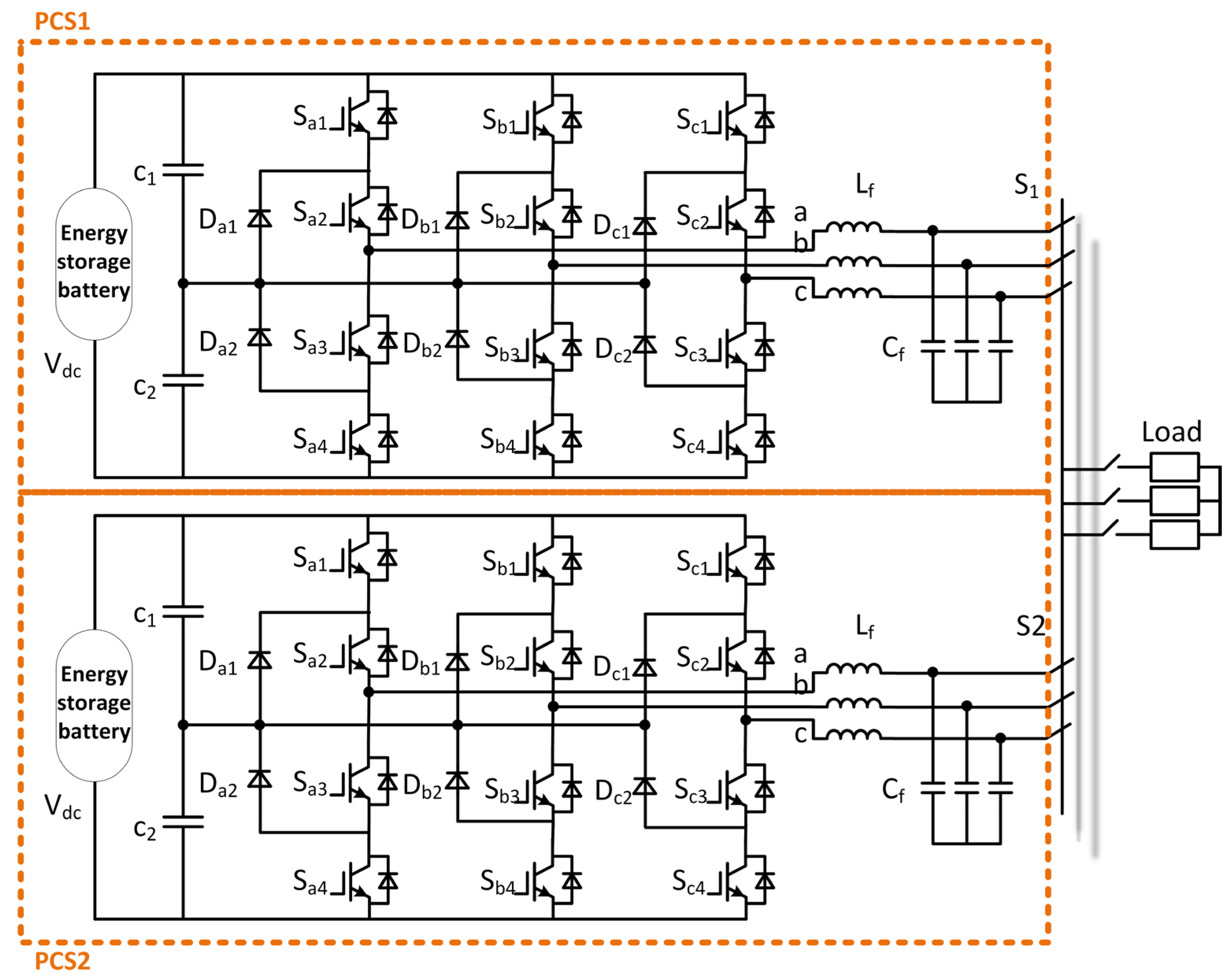
2. PCS Parallel Topology Structure

Compared to two-level converters, three-level converters subject switching devices to significantly lower electrical stress—typically, only half that of their two-level counterparts. At the same switching frequency, the number of output levels is mostly closer to sine, and the harmonic content is small. The three-level converter can output a better waveform at a lower switching frequency, with low switching loss and high system efficiency, which is more suitable for medium- and high-voltage applications [23,24,25]. For the large-capacity energy storage system used in coal mines, a single converter has been difficult to meet the power requirements, and multiple converters in parallel have become a means of system expansion. The topology of the energy storage converter is composed of two independent three-level NPC converters in parallel, as shown in Figure 1.

3. PCS Off-Grid Parallel Control Strategy

In the event of a power failure, the coal mine energy storage system must independently provide emergency power supplies for mine improvement machines, main fan ventilation, and underground emergency drainage, etc., thereby ensuring the safety of underground personnel. When the energy storage converter works in the off-grid parallel operation mode, the difference of control parameters, hardware parameters, and line parameters between PCS modules; the sudden change in external load; or the change in renewable energy power will cause the problem of circulating current and power imbalance [26,27,28].
To achieve the output synchronization of two PCS, this paper proposes a cooperative control method of a power conversion system based on CAN bus. By setting the master–slave machine to use the message object of the CAN module time stamp register MOTS (Message Object Time Stamps) to latch the value of the time stamp counter register CANTSC (Time-Stamp Counter Register) when the slave machine receives the angle signal sent by the master and the actual wave is emitted, the phase of the actual wave of the slave module can be accurately calculated. In addition, the master performs PI closed-loop control based on the set voltage value and the feedback voltage value, and the output value, after being limited, is added to the set voltage value to determine the actual wave-generating voltage. In each control cycle, the master sends the voltage value to the slave via CAN. The slave machine calculates the modulation ratio of the final wave based on the received voltage value and its own power supply, ensuring that the output voltage amplitude of each slave machine is consistent.

3.1. High-Precision Phase Synchronous Control

The phase synchronization control schematic is shown in Figure 2. The master calculates the angle step value of each control cycle according to the set voltage frequency and control cycle, and accumulates according to this value. Whenever the master angle is calculated to zero, the synchronization signal is broadcast to the slave via CAN. The MOTS registers of each slave will lock the CANTSC count after the CAN buffer has received the data. (The time of each slave’s locking is basically the same, but the value of the locking to MOTS will be quite different. Because the power-on sequence of each slave is different, the timing of CANTSC starting from 0 is different).
Each slave CAN buffer that successfully receives the CAN data sent by the master can be considered the same, recorded as δ 0 . The slaves read the value of the CANTSC register at the moment of waveform generation and then subtract the locked CANTSC value in the MOTS register, i.e., the time difference, each slave calculates its own time difference δ t 1 and δ t 2 .
δ t 1 = ( t 1 _ T S C t 1 _ M O T S ) S δ t 2 = ( t 2 _ T S C t 2 _ M O T S ) S
where S is the CAN baud rate.
Adding δ 0 based on the time difference above, it is assumed that the exact delay times δ 1 and δ 2 are from the time the waveform is generated to the time the master sends data (zero crossing).
δ 1 = δ 0 + δ t 1 δ 2 = δ 0 + δ t 2
According to this time, the exact phase angle of each slave, relative to the master when the actual waveform is generated, can be further obtained:
θ 1 = δ 1 f w × 360 ° θ 2 = δ 2 f w × 360 °
where f w is the set voltage frequency, T w = 1 f w .
Since then, each slave machine’s control cycle will accumulate θ step based on the above angle, and the waves can be generated from the perspective of the current calculation, which can improve the accuracy of slave machine synchronization.
θ step = 360 ° × T c f w
θ 1 = θ 1 + θ step θ 2 = θ 2 + θ step
where T c is the control period.

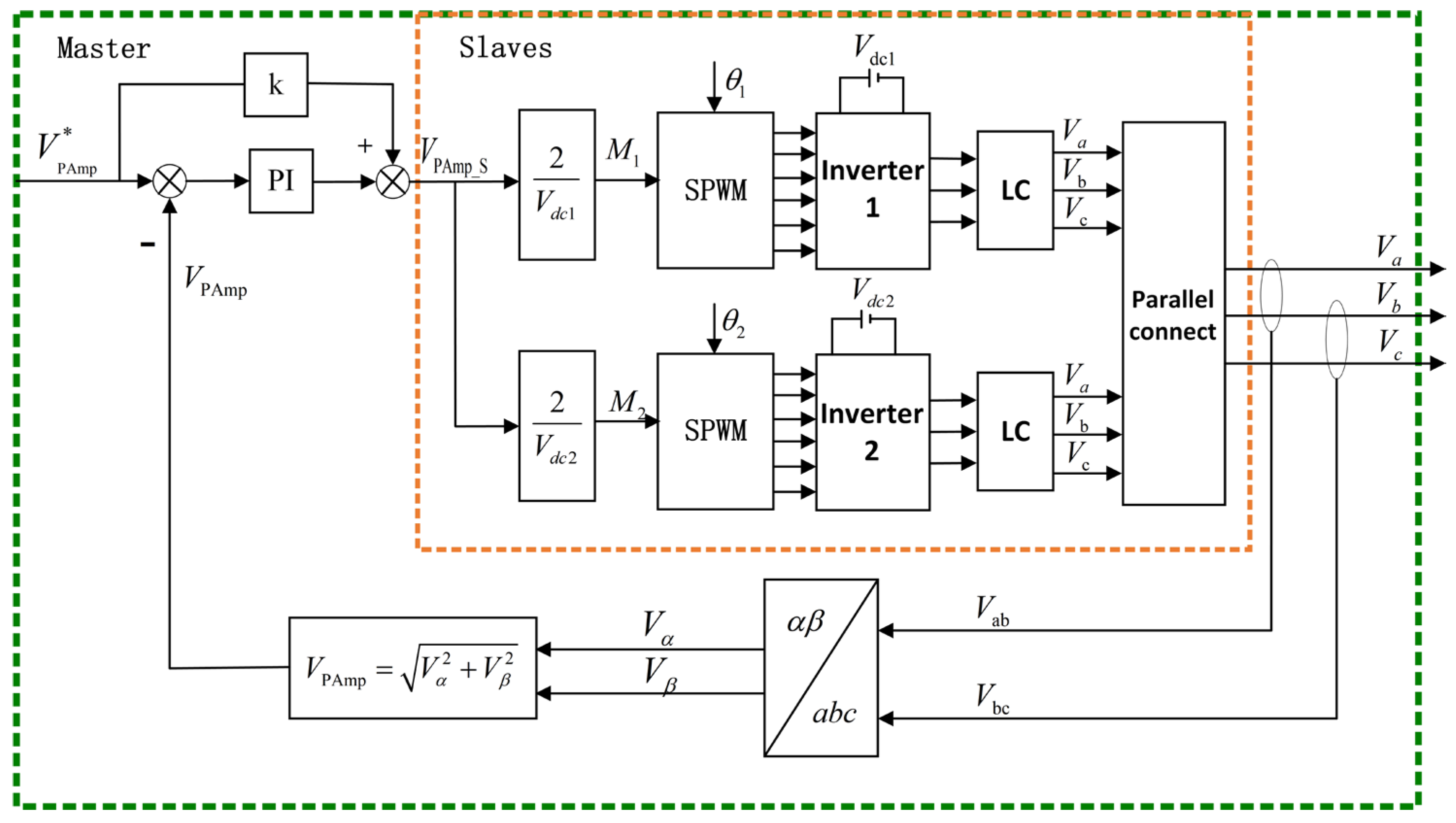
3.2. Parallel Voltage Source Equal Amplitude Control

The energy storage emergency power supply for the coal mine must provide a stable voltage source for the security loads. The master sets the output voltage value of the system, monitors the output voltage value in real time, and maintains the stability of the output voltage by voltage loop control combined with feedforward control. The slave machine calculates the modulation ratio of the final wave according to the voltage value, the SPWM wave generation mode of its own driver, and the bus power supply. Combined with the phase angle of each PCS in the current control cycle, the modulation wave is obtained to realize the cooperative control between the two slaves. The control structure diagram is shown in Figure 3.
When the phase voltage amplitude of the master is set to V PAmp * , the master samples the two line voltages V ab and V bc through the ADC module after the slave is connected in parallel. The two line voltages are converted to the stationary coordinate system to obtain V α and V β , and the output phase voltage amplitude is calculated. The calculation formula is as follows:
V α = 2 3 V ab 1 3 V bc V β = 3 3 V bc
V PAmp = V α 2 + V β 2
Calculate the actual phase voltage amplitude used by the slaves for wave generation. The calculation formula is:
V PAmp _ S = k V PAmp * + P I o u t
k = V max _ M V max _ S
where k is the ratio of the maximum detection voltage of the host and the slave, V max _ M is the maximum detection voltage of the master, V max _ S is the maximum detection voltage of the slave, and P I o u t is the output value of the voltage closed loop.
In each control cycle, the host sends the phase voltage amplitude to each slave via CAN. To adapt to the parallel control, the slave PCS adopts SPWM modulation. According to the phase voltage amplitude sent by the master and the detected PCS DC bus voltage, the modulation ratios of the two slaves can be calculated as follows:
M 1 = V PAmp _ S V d c 1 2 = 2 V PAmp _ S V d c 1 M 2 = V PAmp _ S V d c 2 2 = 2 V PAmp _ S V d c 2

3.3. Three-Level SPWM

To make the inverter generate the SPWM waveform, the sine modulation wave is compared with the triangular carrier wave to obtain the PWM pulse signal to control the on/off of the power switch tube [21]. The positive half-wave of the sinusoidal modulation wave is compared directly with the triangular carrier wave, and the negative half-wave is shifted up as a whole and then compared with the triangular carrier wave, so that the three-level SPWM single carrier wave can be realized, as shown in Figure 4 below.
Solving the intersection point of the modulation wave and the triangular wave to determine the turn-on and turn-off time of the device is difficult, and it is not easy to implement in engineering. In this paper, the integral method is used to calculate the pulse width of the power device. When the SPWM modulation ratio is M and the number of pulse cycles corresponding to half a cycle of the sine wave is n , the center distance of each pulse is the same as π n , the width of the i-th rectangular pulse is σ i , and the phase angle of the center point is θ i , as shown in Figure 5. According to the equivalence principle of equal area [29], the following formula is obtained:
σ i · ( π / n ) = M θ i θ i + π n sin θ d θ = M cos ( θ i + π n ) cos ( θ i )
Further simplification:
σ i = M · n · cos ( θ i + π n ) cos ( θ i ) π
The system’s main control chip uses DSP28335, and there is a problem when generating the SPWM waveform: if the comparison value CMP of the previous PWM cycle is PRD, and in the next PWM cycle is a non-PRD value, the PWMxA/B waveform will lack the red-level change part shown in Figure 6 during the half-cycle of the rising count.
To address the aforementioned waveform anomaly, this paper proposes a PWM complementary pulse width method. The PCS slave predicts the angle for the next control cycle based on the current angle and the modulation ratio, thereby enabling the prediction of the comparison value. If the comparison value for the current control cycle equals the period value (PRD), while the predicted comparison value for the next cycle is a non-PRD value, the current comparison value is adjusted to PRD-1. This ensures proper PWM pulse generation and eliminates missing pulse width issues. The pulse width compensation flowchart is shown in Figure 7.

3.4. Parallel Control of PCS Based on CAN Bus

The PCS CAN bus network consists of one master and two slaves. Depending on whether or not the slave PCS has a PWM output, the parallel control is divided into two stages: the first stage is the pre-parallel preparation stage (the slave does not have a PWM output), and the second stage is the parallel operation stage (the slave has a PWM output).
By formulating a communication protocol, the first stage is the preparation stage before parallel operation. Before the master starts, the shutdown command is sent to the slave; after the master starts, each time at the zero crossing of the angle, the master sends a broadcast to the slaves to ask if they are ready to generate waves, and the slaves respond according to their own situation. When all the slaves are ready to generate waves, the master sends the permitted wave command to the slaves by broadcasting at the zero crossing of the angle, and then enters the next stage. The second stage is the master–slave cooperative operation control stage. The master transmits synchronization and voltage amplitude information to the slave at the angle zero crossing; in the non-angle zero crossing control period, the master transmits only the voltage amplitude information. The flow chart of the master sending instructions to the slave is shown in Figure 8, and the master–slave cooperative control diagram based on CAN communication is shown in Figure 9.
Although this paper illustrates the control method with two slaves configuration, the proposed master–slave collaborative control strategy for energy storage inverters based on the CAN bus is scalable to multiple slaves. In the master–slave parallel control method based on the CAN bus, the master sends synchronization and voltage amplitude signals, and each slave generates its waveform based on the signals from the master and its own power supply conditions. Since each slave operates independently, the number of parallel slaves can be flexibly configured according to the energy storage system’s capacity requirements. The PCS slaves are designed with a modular structure, where both the control and power units are modular, making expansion easier. This design enhances system reliability, and in the event of a system fault, modular maintenance and replacement are quick and convenient.
The safe and stable operation of the system is particularly important in practical applications such as coal energy backup. A dedicated CAN bus for parallel operation is set up to reduce the number of nodes and alleviate the network load. To shield against signal interference, a bus isolator is added, and a CAN network communication fault diagnosis function is configured. When communication errors reach a preset threshold, the system will initiate a shutdown process. The system is equipped with over-/undervoltage protection, bias voltage protection, overcurrent protection, and overtemperature protection to prevent cascading failures and ensure the safety and reliability of the system.

4. Experimental Result

In order to verify the effectiveness of the parallel cooperative control method of the energy storage converter based on the CAN bus master–slave mode, the experimental platform shown in Figure 10 is built. The PCS main control chip is TMS320F28335 (Texas Instruments, Dallas, TX, USA), three-phase AC voltage regulator power supply AC280V, corresponding to DC power supply 400 V. The AC filter inductance value is 1 mH, the capacitance value is 20 μF, and the corner connection and line resistance load is 25 Ω. The integrated SPWM modulation strategy is adopted, the PWM frequency is 2 kHz, and the CAN communication baud rate is 500 kbps.
Figure 11 shows the waveform of a data frame in which the master asks the slaves if they are ready to generate a waveform, and the slaves respond during the pre-parallelization preparation phase.
In the pre-parallel preparation stage, the protocol is formulated so that the master sends 5 bytes of query data to the slaves, and slave 1 and slave 2 each return 2 bytes of data to the master after receiving the query. Since the frame ID number set by slave 1 is smaller than the frame ID of slave 2, even if two slaves return data to the master at the same time, it is still guaranteed that slave 1 will return first, and slave 2 will return later.
The CAN standard frame consists of a 1-bit start of frame (SOF), a 12-bit arbitration segment (11-bit ID + 1-bit RTR), a 6-bit control segment (1-bit IDE + 1-bit r0 + 4-bit DLC), bytes × 8-bit data segment, a 17-bit CRC segment (16-bit CRC + 1-bit delimiter), a 2-bit ACK segment (1-bit ACK + 1-bit delimiter), and a 7-bit end of frame (EOF). Composed of 5 bytes corresponding to 85 bits of data, 2 bytes corresponding to 61 bits of data, the minimum interval between two frames of data is 3 bits of data; 500 kbps corresponds to 2 μs per bit, so this process takes (85 + 3 + 61 + 3 + 61) × 2 = 426 μs; in consideration of the bit padding and so on, the total time corresponds to the same as 430 μs in Figure 11.
Figure 12 shows the comparison of U-phase PWM waveforms before and after pulse width compensation in the integral SPWM mode. R1 and R2 are the U-phase Sa1 and Sa4 drive waveforms before pulse width compensation, and channel 1 and channel 2 are the U-phase Sa1 and Sa4 drive waveforms after pulse width compensation. It can be seen from the diagram that there is no fill pulse width in the U-phase Sa1 drive; because the comparison value does not contain the PRD value, Sa4 corresponds to the negative half-wave, the comparison value is shifted upward of PRD, so the narrow pulse width is supplemented.
Figure 13 shows the output line voltage waveforms of the two slaves when they are not connected in parallel, with the phase voltage amplitude set to 80 V.
As can be seen from the figure, the voltage amplitude and phase of the two slaves are almost identical, with a small synchronization error.

4.1. Output Phase Voltage Amplitude at 80 V

In the off-grid mode, the AC power supply is 140 V, and the output phase voltage amplitude is set to 80 V. The experimental results of the parallel system are shown in Figure 14.
It can be seen from the figure that the corresponding DC bus is approximately 190 V. The positive and negative half-voltage values of the two slaves are close, and the positive and negative half-voltage deviations of each PCS are small, basically within 1 V.
The master theta at the bottom left of Figure 14 indicates the master angle calculated at the moment of wave generation, corresponding to δ 1 and δ 2 in Section 3.1, in the current control cycle after the master has sent a synchronization signal when the angle crosses zero and the slave has received the synchronization signal, and this value is held constant in a sinusoidal cycle. Since the master sends 6 bytes of data when sending the synchronization signal, it takes about 186 μs, which corresponds to an electrical angle of 3.348° for a 50 Hz sine wave. Since a control period of 500 μs corresponds to an electrical angle of 9°, the range of the master angle in the graph should be between 3.348° and 12.348°. The synchronization angle of the master calculated by the two slaves at the time of wave generation is different; because the carrier of the two slaves controllers has a phase difference, the wave generating time is fixed relative to the carrier, so there is a time difference in the angle of the master calculated at the time of wave generation.
In principle, the output power of the two slaves is divided equally. According to the amplitude of the output phase voltage of 80 V and the phase resistance of 12.5 Ω, the total output power should be 768 W. As can be seen from the figure, the output power of two slaves is approximately 380 W. The average value of the PCS1 output power is 374 W, and the average value of the PCS2 output power is 382 W; the total output power is 756 W. Define the power balance index (PBI) as the ratio of the difference between the output power of each module to the total power, and the result is 1.06%.
P B I = P out 1 P o u t 2 P o u t 1 + P o u t 2 × 100 %
Channel 1 in Figure 15 is the UV line voltage measured at the parallel point. Channel 2 is the line voltage waveform output by the PCS1 slave before LC filtering. The energy storage converter uses a three-level topology, so the line voltage is five-stage. Channel 3 and channel 4 are the current waveforms of PCS1 and PCS2 flowing through the filter inductor. It can be seen from the figure that the amplitude and phase of the two current waveforms are basically the same, and the sum of the two currents corresponds to the calculated value of 80 V/(25 Ω/2), 6.4 A.
As shown in Figure 16, the FFT analysis of the UV line voltage after LC filtering shows that the amplitude is 137.7 V, which corresponds to the line voltage amplitude of 138.6 V calculated from the set phase voltage amplitude of 80 V; the output voltage deviation is 0.65%, and the total harmonic distortion (THD) is only 0.65%.

4.2. Output Phase Voltage Amplitude at 160 V

In the off-grid mode, the AC power supply is 280 V, and the output phase voltage amplitude is set to 160 V. The experimental results of the parallel system are shown in Figure 17.
It can be seen from the figure that the corresponding DC bus is about 370 V. The positive and negative half-voltage values of the two slaves are close, and the positive and negative half-voltage deviations of each PCS are small, basically within 1.5 V.
The difference between the master synchronization angles calculated by the two slaves is small, indicating that the carrier phase difference of the two PCS controllers is also small.
According to the setting of the output phase voltage amplitude of 160 V and the phase resistance of 12.5 Ω, the total output power should be calculated to be 3072 W. From the following figure, it can be seen that the power difference between the two PCS outputs is approximately 100 W, with the power being nearly equally divided. The average value of the PCS1 output power is 1594 W, and the average value of the PCS2 output power is 1504 W; the total output power is 3098 W, and the power balance index result is 2.91%.
Channel 1 in Figure 18 is the UV line voltage measured at the parallel point. Channel 2 is the line voltage waveform output by the PCS1 slave before LC filtering. The energy storage converter uses a three-level topology, so the line voltage is five-level. Channel 3 and channel 4 are the current waveforms of PCS1 and PCS2 flowing through the filter inductor; it can be seen from the figure that the amplitude and phase of the two current waveforms are basically the same, and the sum of the two currents corresponds to the calculated value of 160 V/(25 Ω/2), 12.8 A.
As shown in Figure 19, the FFT analysis of the UV line voltage after LC filtering shows that the amplitude is 278.3 V, which corresponds to the line voltage amplitude of 277.1 V calculated from the set phase voltage amplitude of 160 V; the output voltage deviation is 0.43%, and the total harmonic distortion (THD) is only 0.52%.

5. Conclusions

In this paper, an off-grid parallel cooperative control method of energy storage converter based on CAN bus has been proposed. The message object time stamp register MOTS and time counter CANTSC of the CAN module are used to accurately obtain the phase of the modulation wave relative to the host when the actual wave is generated by each slave, so as to ensure that the phase of the output voltage of the two slaves is consistent.
The integral method is used to calculate the pulse width of the power tube, and the three-level single-carrier SPWM is realized. To solve the problem of the missing half-pulse width when switching from positive half-wave to negative half-wave, it is proposed to predict the comparison value of the next control cycle. If the comparison value is PRD and the next comparison value is not PRD, the pulse width is supplemented by modifying the comparison value.
A parallel experimental platform of one master and two PCS slaves has been established. The results verify the effectiveness of the proposed method, the output power of the two slaves is balanced, and the stable operation of the parallel system is realized. When the output phase voltage amplitude is 80 V, the corresponding voltage deviation is 0.65%, the THD is 0.65%, and the power balance index result is 1.06%. When the output phase voltage amplitude is 160 V, the corresponding voltage deviation is 0.43%, the THD is 0.52%, and the power balance index result is 2.91%. With this technology, multiple devices can be connected in parallel to achieve the purpose of power conversion system expansion.

6. Patents

A patent has been filed based on the results of this study:
Inventors: Mengmei Zhu, Guangxu Zhou, Lei Guo, Yipei Wang, Hongzhang Lv, and Sheng Chu. “A collaborative control method for power conversion system based on CAN bus.” Chinese Patent Application No. CN202411159139.0, filed August 2024 (Pending).

Author Contributions

Conceptualization, M.Z.; methodology, M.Z.; software, M.Z. and S.C.; validation, M.Z. and L.G.; formal analysis, M.Z. and N.S.; investigation, G.Z. and Y.W.; resources, G.Z. and H.L.; data curation, M.Z.; writing—original draft preparation, M.Z.; writing—review and editing, G.Z.; visualization, G.Z.; supervision, G.Z.; project administration, G.Z. and H.L.; funding acquisition, G.Z. and H.L. All authors have read and agreed to the published version of the manuscript.

Funding

This research was supported in part by the Qingdao Key Technology Research Project under Grant 25-1-1-gjgg-4-gx; in part by the Shandong Province “Double-Hundred Talent Plan” under Grant WST2024010; in part by the Science and Technology Small and Medium-sized Enterprises Innovation Ability Enhancement Project of Shandong Province under Grant 2024TSGC0162 and Grant 2024TSGC0826; and in part by the Key R&D Program of Shandong Province under Grant 2022CXGC020404 and Grant 2023CXGC010202.

Data Availability Statement

The data presented in this study are available on request from the corresponding author.

Conflicts of Interest

Author Hongzhang Lv and Sheng Chu were employed by Qingdao Veccon Electric Co., Ltd. The remaining authors declare that the research was conducted in the absence of any commercial or financial relationships that could be construed as a potential conflict of interest. The authors declare that the funder was not involved in the study design, collection, analysis, interpretation of data, the writing of this article or the decision to submit it for publication.

References

  1. Sun, G.; Zhang, Q.; Shi, C.G.; Zhang, C.X.; Fu, M.Y.; Guo, X.W. Design and Application of Low Voltage Parallel Emergency Energy Storage Third Power Supply System for Coal Mines. Henan Sci. Technol. 2023, 42, 74–81. [Google Scholar]
  2. Hussain, A.; Li, D.; Luo, Y.; Zhang, H.Z.; Zhang, H.M.; Li, X.F. Porous membrane with improved dendrite resistance for high-performance lithium metal-based battery. J. Membr. Sci. 2020, 605, 118108. [Google Scholar] [CrossRef]
  3. Deng, Y.G.; Hussain, A.; Raza, W.; Ao, L.H.; Zong, K.; Zhao, J.; Liu, W.; Ye, P.F.; Ramiere, A.; Cai, X.K.; et al. Morphological modulation of the PBI membrane and performance optimization for Li-metal battery. Chem. Eng. J. 2023, 474, 145800. [Google Scholar] [CrossRef]
  4. Díaz-González, F.; Heredero-Peris, D.; Pagès-Giménez, M.; Prieto-Araujo, E.; Sumper, A. A Comparison of Power Conversion Systems for Modular Battery-Based Energy Storage Systems. IEEE Access 2020, 8, 29557–29574. [Google Scholar] [CrossRef]
  5. Zhu, L.F.; Wu, B.F.; Song, N.L.; Liu, Z.Z.; Yang, C.G.; Liu, R. Modelling and Additional Control for Parallel Operation of Power Converters in ESS under Master-slave Scheme. Proc. CSU-EPSA 2022, 34, 74–81. [Google Scholar]
  6. Kim, K.T.; Kwon, J.M.; Kwon, B.H. Parallel operation of photovoltaic power conditioning system modules for large-scale photovoltaic power generation. IET Power Electron. 2014, 7, 406–417. [Google Scholar] [CrossRef]
  7. Liu, X.; Zhao, L.; Zhang, J.X.; Shi, S.S.; Ma, J.; Yu, H.R. Research on Energy Storage System Based on Master-slave Control Paralleled Three-level Converter. Electr. Drive 2014, 44, 27–31. [Google Scholar]
  8. Aquib, M.; Vijay, A.S.; Doolla, S.; Chandorkar, M.C. On circulating current mitigation for modular UPS/Inverters. IEEE J. Emerg. Sel. Top. Power Electron. 2023, 11, 1179–1190. [Google Scholar] [CrossRef]
  9. Dalboni, M.; Soldati, A. Distributed Controller for the Parallel Operation of Power Converters with Small Output Filters. IEEE Open J. Power Electron. 2024, 5, 1297–1308. [Google Scholar] [CrossRef]
  10. Zhang, J.W.; Huang, X.L.; Zhou, J.Q.; Fan, X.M.; Shi, G.; Zang, J.J.; Yang, X.W.; Cai, X. A Capacity-Expandable Cascaded Multilevel Energy Storage System Based on Laminated Power Modules. IEEE Trans. Power Electron. 2025, 40, 5265–5278. [Google Scholar] [CrossRef]
  11. Li, J.L.; Ding, Z.Y.; Liu, H.T.; Yang, H. Research on Grid-Forming Energy Storage Converters and Control Strategies. Power Gener. Technol. 2022, 43, 679–686. [Google Scholar]
  12. Luo, N.H.; Gu, S.; Yao, X.; Huang, C.; Yan, P.; Zhao, C. Parallel Circulation Current Suppression of Three–level Inverter Based on FPGA. Ind. Control Comput. 2019, 32, 139–140. [Google Scholar]
  13. Xu, T.; Gao, F.; Liu, H.T.; Wang, X.F.; Blaabjerg, F. A Carrier Synchronization Method for Global Synchronous Pulsewidth Modulation Application Using Phase-Locked Loop. IEEE Trans. Power Electron. 2019, 34, 10720–10732. [Google Scholar] [CrossRef]
  14. Yang, H.K. Research on Parallel Operation Control Technology of the Battery Energy Storage Converter in New Energy Stations. Electr. Mach. Technol. 2024, 4, 13–18. [Google Scholar]
  15. Roncero-Clemente, C.; Gonzalez-Romera, E.; Barrero-Gonzalez, F.; Milanes-Montero, M.I.; Romero-Cadaval, E. Power-Flow-Based Secondary Control for Autonomous Droop-Controlled AC Nanogrids with Peer-to-Peer Energy Trading. IEEE Access 2021, 9, 22339–22350. [Google Scholar] [CrossRef]
  16. Ding, M.; Tao, Z.L.; Hu, B.; Tan, S.J.; Yokoyama, R. Parallel Operation Strategy of Inverters Based on an Improved Adaptive Droop Control and Equivalent Input Disturbance Approach. Electronics 2024, 13, 486. [Google Scholar] [CrossRef]
  17. Zheng, R.N.; Han, H.; Li, G.J.; Ge, X.H. A local master-slave coordinated control strategy for series-parallel inverter microgrids. Power Syst. Prot. Control 2020, 48, 47–56. [Google Scholar]
  18. Liu, P.; Bi, Y.; Liu, C. Data-Based Intelligent Frequency Control of VSG via Adaptive Virtual Inertia Emulation. IEEE Syst. J. 2022, 16, 3917–3926. [Google Scholar] [CrossRef]
  19. Zhang, C.X.; Li, C.B.; Feng, W.; Sun, K.; Xia, Y.W.; Liu, Q. A Coordinated Transient Power Fluctuation Suppression Strategy for Power Conversion System in Islanded PV/Storage Microgrid. Proc. CSEE 2018, 38, 2302–2314. [Google Scholar]
  20. Sun, P.; Yao, J.; Zhao, Y.; Fang, X.; Cao, J.Y. Stability Assessment and Damping Optimization Control of Multiple Grid-connected Virtual Synchronous Generators. IEEE Trans. Energy Convers. 2021, 36, 3555–3567. [Google Scholar] [CrossRef]
  21. Guan, Y.; Guerrero, J.M.; Zhao, X.; Vasquez, J.C.; Guo, X. A new way of controlling parallel-connected inverters by using synchronous-reference-frame virtual impedance loop–Part I: Control principle. IEEE Trans. Power Electron 2016, 31, 4576–4593. [Google Scholar] [CrossRef]
  22. Espina, E.; Llanos, J.; Burgos-Mellado, C.; Cárdenas-Dobson, R.; Martínez-Gómez, M.; Sáez, D. Distributed Control Strategies for Microgrids: An Overview. IEEE Access 2020, 8, 193412–193448. [Google Scholar] [CrossRef]
  23. Yuan, L.; Qing, Y.; Jiang, Y.H.; Xu, A.F. A New Neutral-point Voltage Balance Control Based on Virtual Space Vector Modulation for Three-Level NPC Converter. J. Electr. Eng. Technol. 2023, 18, 971–980. [Google Scholar] [CrossRef]
  24. Liu, L.; Zhang, Z.B.; Yin, Y.F.; Vazquez, S.; Zhao, Y.X.; Kennel, R. An Efficient Robust Power-Voltage Control for Three-Level NPC Converters in Micro grids. IEEE Trans. Ind. Inform. 2024, 20, 5849–5863. [Google Scholar] [CrossRef]
  25. Zhou, J.H.; Sun, Y.F.; Chen, S.S.; Lan, T.F. A Fast Repetitive Control Strategy for a Power Conversion System. Electronics 2024, 13, 1186. [Google Scholar] [CrossRef]
  26. Wu, Y.L.; Ge, L.; Yuan, X.D.; Fu, X.Y.; Wang, M.S. Adaptive Power Control Based on Double-layer Q-learning Algorithm for Multi-parallel Power Conversion Systems in Energy Storage Station. J. Mod. Power Syst. Clean Energy 2022, 10, 1714–1724. [Google Scholar] [CrossRef]
  27. Li, J.L.; Xu, S.H.; Hui, D. A review of stability analysis and control strategy of multi-parallel PCS for analysis and control strategy of multi-parallel PCS for hundred MW level energy storage power station. Proc. CSEE 2016, 36, 4034–4047. [Google Scholar]
  28. Park, T.W.; Kim, R.Y.; Lee, J.H. An Instantaneous Load-Sharing Parallel Control Method Using Improved PWM-Capture With DMA in a Power Conversion System. IEEE Access 2024, 12, 29660–29672. [Google Scholar] [CrossRef]
  29. Wang, L.Q.; Zhang, J.L.; Guan, C.G.; Zhang, X.F. Research on Single-Phase Current Source Inverter Based on Nonlinear Carrier Modulation. Acta Energiae Solaris Sin. 2021, 42, 435–442. [Google Scholar]
Figure 1. Two-machine parallel topology structure of energy storage converter.
Electronics 14 02010 g001
Figure 2. Phase synchronization control scheme.
Electronics 14 02010 g002
Figure 3. Parallel voltage source equal amplitude control block diagram.
Electronics 14 02010 g003
Figure 4. Three-level SPWM with single carrier wave.
Electronics 14 02010 g004
Figure 5. SPWM pulse width equivalent calculation.
Electronics 14 02010 g005
Figure 6. SPWM negative half-wave missing pulse width.
Electronics 14 02010 g006
Figure 7. Pulse width compensation flowchart.
Electronics 14 02010 g007
Figure 8. Flowchart of sending instructions from master to slave.
Electronics 14 02010 g008
Figure 9. Master–slave cooperative control chart based on CAN communication.
Electronics 14 02010 g009
Figure 10. Experimental platform.
Electronics 14 02010 g010
Figure 11. One master and two slaves CAN communication data frame waveform.
Electronics 14 02010 g011
Figure 12. U-phase drive waveform with or without pulse width comparison diagram.
Electronics 14 02010 g012
Figure 13. Line voltage waveform when two slaves are not connected in parallel.
Electronics 14 02010 g013
Figure 14. Two PCS experimental results.
Electronics 14 02010 g014
Figure 15. Waveform when the phase voltage is set to 80 V.
Electronics 14 02010 g015
Figure 16. FFT analysis of the UV line voltage.
Electronics 14 02010 g016
Figure 17. Two PCS positive and negative half-voltage values.
Electronics 14 02010 g017
Figure 18. Waveform when the phase voltage is set to 160 V.
Electronics 14 02010 g018
Figure 19. FFT analysis of UV line voltage.
Electronics 14 02010 g019
Disclaimer/Publisher’s Note: The statements, opinions and data contained in all publications are solely those of the individual author(s) and contributor(s) and not of MDPI and/or the editor(s). MDPI and/or the editor(s) disclaim responsibility for any injury to people or property resulting from any ideas, methods, instructions or products referred to in the content.

