1. Introduction
In contrast to traditional intravehicular activities, current in-orbit operations and future planetary explorations require astronauts to carry out EVAs (extravehicular activities) with thick and heavy extravehicular spacesuits, requiring good mobility and flexibility of the upper and lower limb joint systems of the spacesuit. However, due to pressure protection, a multilayer EVA spacesuit will produce obvious resistance torque, which increases the extra physical energy expenditure, limits joint mobility, and reduces ergonomic performance [
1]. The most robust metric for evaluating exoskeleton assistance efficiency is metabolic energy consumption during human–exoskeleton movement, including heat production, moisture generation, CO
2 emissions, and oxygen consumption. Current measurement approaches primarily involve two types of systems: high-precision oxygen analysis systems and wearable devices that estimate maximum oxygen uptake based on users’ physiological parameters. These metabolic indicators provide objective criteria for assessing spacesuit exoskeleton systems’ assistance performance. Therefore, an active spacesuit was introduced in our previous research [
2], that is, a joint-assisted exoskeleton robot that could be worn directly outside spacesuits to enhance operational capability, as well as to assist astronauts in overcoming the influence of joint resistance torque and equipment load [
3]. In the human–spacesuit system, the control of a joint-assisted exoskeleton robot aims to minimize the workload for astronauts when accomplishing EVA tasks, such that human effort can be reduced in the execution [
4]. In order to address this issue, this paper proposes a control method to deal with human–spacesuit interaction (HSI) with minimum interaction force and trajectory tracking errors [
5].
Additionally, many requirements must be met to obtain good control effects in engineering applications using exoskeleton robots [
6], such as good adaptability to different wearers or to the same wearer in different states, high accuracy in robot dynamics, and a certain feasibility in wearable devices with limited hardware resources [
7]. Admittance control, also called position-based impedance control, features the force impedance correction outer loop and position control inner loop [
8]. When there is a contact interaction, the actual interaction force measured by the sensor is transformed into a correction for the desired trajectory input, and the position control inner loop tracks the corrected trajectory. Different interaction effects can be achieved by adjusting the spring, damper, and mass coefficients. Currently, admittance control is also widely used in applications using exoskeleton robots. In [
9], a simple admittance controller was formulated for a dual robot upper-limb stroke rehabilitation system. In [
10], admittance motion control was proposed for an omnidirectional-type cane robot, with the virtual mass and damper coefficients as constants and the stiffness coefficient neglected. In [
11], a variable admittance controller was designed to generate the reference trajectory and reduce human–exoskeleton interaction torque; the control parameters were self-regulated based on the defined uncertainty index of gait prediction. In [
12], admittance control was proposed that included an inner-loop controller with guaranteed robustness and stability and an outer-loop controller with a specific performance task model. While these studies [
4,
5,
6,
7,
8,
9,
10,
11,
12] have demonstrated effective solutions for controlled laboratory conditions and predictable motions, there are significant limitations in applying them to the complex dynamics of spacesuit-assisted extravehicular activities. Existing approaches either assume constant environmental parameters or require precise dynamic models, assumptions that break down when dealing with the time-varying stiffness of pressurized spacesuits, unpredictable astronaut movements, and the stringent computational constraints of space-grade systems. Inspired by [
4]’s variable stiffness concept but extending beyond these limitations, we propose an adaptive admittance control with time-varying stiffness parameters that dynamically adjusts to real-time interaction forces while compensating for unmodeled dynamics through neural network approximation. In [
4], admittance control with variable stiffness was presented to deal with a human subject’s intention, as well as the unknown inertia masses and moments in robotic dynamics; then, adaptive control was proposed to deal with the uncertain robotic dynamics and a stability criterion could be obtained.
On the basis of the above schemes, an adaptive admittance control with a time-varying stiffness parameter is proposed to deal with different humans’ motion intentions, as well as the uncertainty in the robotic dynamic model, so that it can perform more effectively in the actual HSI system. Specifically, considering the modeling error of the robotic dynamic model and uncertainty factors such as unpredictable disturbance, friction, and workload change in the HIS system, a position inner loop based on adaptive robust fuzzy control is proposed to enhance the tracking performance for a given reference trajectory, and the force impedance correction outer-ring with time-varying stiffness is presented to deal with wearers’ motion intention. In addition, for different wearers or for the same wearer in different states, an adaptive RBF (radial basis function) neural network is proposed to approximate the variable HSI model. The HSI system is shown in
Figure 1. The contributions of this paper are summarized as follows:
(1) A novel adaptive RBF neural network control approach is proposed for HSI model approximation.
(2) An innovative adaptive admittance control system integrating robust fuzzy control and time-varying impedance is developed.
(3) The significant reduction of 15.88% in oxygen consumption is achieved in lunar surface sampling validation.
2. Human–Spacesuit Interaction System
In the kinematic analysis of active spacesuits, it is generally considered that there is good coupling between the active spacesuit and the wearer and the motion trends are consistent. In fact, a pressurized spacesuit has a large motion space, and deviation from the wearer’s limbs’ rotation center results in angle deviation, as shown in
Figure 1. This angle deviation will produce an interactive force, ignoring the influence of the flexible connection between the extravehicular spacesuit and the joint-assisted exoskeleton robot in the active spacesuit. The HSI force is a linear combination of rigidity, spring, and damping, which can be expressed as follows [
13]:
where
is the interaction force, and
,
, and
are, respectively, the elastic coefficient, damping coefficient, and inertial coefficient of the HIS system for the joint motion angle of the wearer’s limbs and active space.
In practice, the interaction force can be obtained through multi-dimensional force sensors, and different interaction effects can be achieved by adjusting the above coefficients. A large interaction force will cause muscle fatigue, reduce the speed of limbs’ motion, and even cause muscle damage to astronauts. The parameters of the HSI system are unknown and inconsistent for different wearers; even for the same wearer in different working conditions, the wearer’s own strength will decrease due to muscle fatigue as the working time increases, which also changes the model parameters. The RBF neural network is a three-layer forward structure proposed by J. Moody and C. Darken [
14], which has many advantages such as a simple structure, fast learning convergence, good approximation ability, and the ability to approximate arbitrary continuous functions with a certain accuracy. In this paper, the ideal HSI model is assumed to correspond to Equation (1), and an adaptive RBF neural network control is proposed to approximate the variable HSI model as a whole.
2.1. Controller Design and Convergence Analysis
Equation (1) can be expressed as
where
is the interaction force, and
is the unknown external interference, with
;
,
, and
constitute a symmetric positive definite matrix, where
,
, and
, and
and
are the joint motion angles of the wearer’s limbs and active spacesuit.
The sliding mode function is designed as
where
and
.
The designed controller can be expressed as
where
is the diagonal matrix,
is unknown, and the RBF neural network is adopted to approximate it. The actual output is
where
is the estimated value of the uncertainty term
,
is the estimated value of the weight function, and
is the hidden layer basis vector.
Substitute Equation (5) into Equation (4) to obtain
where
is the robust term, which is composed of the approximation error of the RBF neural network and the unknown external disturbance
,
,
. Therefore, the robust term can be written as
.
The uncertainty term
of the HSI model can be written as
where
,
,
, the coefficients in the uncertainty term,
can be approximated as
,
, and
, and
The adaptive law is designed as
where
,
, and
are symmetric matrices and
,
, and
are all greater than 0.
The Lyapunov function is defined as
where
,
and its derivative with respect to time; we can obtain
Substitute Equation (9) into Equation (11) to obtain
where
where
.
To obtain , , , or is required.
2.2. Approximation Performance
The parameter values of the HSI model are shown in
Table 1. In the adaptive RBF neural network, the number of neurons is 5 and the node center parameter
c_M,
c_D,
c_P is [−1, −0.5, 0, 0.5, 1]; the base width parameter is 20.
kM =
kD = kP = 0.01,
FM = [7, 0; 0, 3],
FD = [500, 0; 0, 300],
FP = [10,000, 0; 0, 5000],
= [35, 0; 0, 35],
KV = [10, 0; 0, 10],
[2, 0; 0, 2]. In order to obtain the trajectory tracking effect more obviously, a motion angle and angular velocity tracking error of 10–100% of the walking cycle and the HSI force are selected, as shown in
Figure 2.
The variable HSI model represents different wearers or the same wearer in different work states. It can be seen from
Figure 2 that when the parameters of the HSI model change, the output trajectory of the ideal HSI model has a better tracking effect on the desired trajectory, and the trajectory tracking error gradually converges to 0, proving that the adaptive RBF neural network control has a better approximation performance on the variable HSI model.
3. Adaptive Admittance Control
Admittance control, also known as position-based impedance control, consists of a force impedance correction outer loop and a position inner loop [
15]. When there is contact interaction between the active spacesuit and the wearer, the actual HIS force measured by the sensor transforms into the correction of the desired trajectory input, and the position inner loop tracks the corrected trajectory. Considering the minimization of the HSI force and the trajectory tracking error, the cost function of the control system can be expressed as [
4]
where
and
are the norms of the matrix, while
R and
G are the weights. Then, there is a balance between the HSI force and the trajectory tracking error.
The goal of the admittance controller is to make the trajectory error e and the HSI force
conform to the set second-order dynamic relation, which can be expressed as
where
M,
B, and
K are the inertia matrix, damping matrix, and stiffness matrix, respectively, which can be adjusted according to different control objectives and scenarios to reduce the cost function of Equation (14).
The functional block diagram of adaptive admittance control is shown in
Figure 3. Firstly, the position inner loop control ensures the fast response and accurate tracking performance of the active spacesuit according to the given reference track. Then, the adaptive RBF neural network controller in
Section 2.1 is used to increase the adaptability to the HSI force of different wearers or the same wearer in different working conditions. In practical applications, the “Simulated lunar sample collection mission” is the motion information of the wearer through some IMU (Inertial Measurement Unit) sensors, and the “Spacesuits’ joint resistant torque” is predicted by the identified Jiles–Atherton hysteretic model [
16].
3.1. Position Inner Loop
Admittance control transforms the force tracking problem of the exoskeleton robot system into a position tracking problem, and its control effect mainly depends on the control performance of the position inner loop [
17]. Therefore, the design of a high-performance position inner-loop controller ensures that the active spacesuit can track accurately according to the given reference trajectory. Fuzzy logic control and the related theorem were developed and defined by Zadeh in 1974 and showed a good control effect on nonlinear objects with time-varying and hysteresis characteristics [
18]. In the actual HSI system, there are uncertainties such as interference, friction, equipment load change, and modeling errors; these factors will seriously affect the trajectory tracking effect of the exoskeleton robot. In addition, adaptive robust control is introduced in the design of the fuzzy controller to enhance stability.
3.1.1. Preliminaries and Problem Formulation
The dynamics of an active spacesuit interacting with the wearer can be described as follows:
where
are the joint angle, angular velocity, and angular acceleration variable coordinates of the joint-assisted exoskeleton robot, respectively;
,
, and
are the inertia matrix of the symmetric positive definite, the centripetal and Coriolis torques, and the torque of gravity contributed by the robotic exoskeleton, respectively; and
,
,
, and
are the HIS torque, the spacesuit’s joint resistant torque, the unknown external disturbance, and the controller torque input, respectively. The exoskeleton robot system usually needs to meet the following structural properties [
19]:
Property 1. is the symmetric positive definite and bounded.
Property 2. is the skew-symmetric matrix.
Property 3. There exists a vector P with components depending on the exoskeleton robot parameters, such as for the dynamics (15), , with being the dynamic regressor matrix, andbeing a vector of differentiable function.
According to the nonlinear system in Equations (16) and (17), the nonlinear system of joint-assisted exoskeleton robot can be expressed as
where the state vector
,
u and
y are the system input and output vector, and
and
are unknown nonlinear functions.
By designing the control law
, all vectors of the closed-loop system can be guaranteed to be bounded, and the output
of the system can track the desired trajectory
. The filtering trajectory tracking error function of the system is defined as
where
,
, and the derivation can be expressed as
where
,
.
After defining
,
, Equation (18) can be expressed as
Additionally, the system needs to meet the following assumptions [
20]:
Assumption 1. The desired trajectory and the twice differentiable are bounded.
Assumption 2. is a positive definite matrix, and there are real numbers , and is satisfied.
3.1.2. Control Algorithm
When the nonlinear functions
and
are known, the control rate
is expressed as
where
,
.
However,
and
are unknown and need to be approximated by fuzzy systems. By using a Gaussian fuzzifier, product inference engine, and center-of-gravity average defuzzifier to design the fuzzy system, the output can be expressed as
where
and
are the basis function, and
and
are adaptive adjustment parameter vectors [
21].
Define , ( = 1, 2, 3, 4 = 1, 2, 3).
In order to ensure the nonsingularity of
, use its generalized inverse
.
where
is a smaller positive real number and
is the identity matrix.
The control law
can be designed as
where
, and the robust control term is
where
.
Since the upper bound of the approximation error is unknown, online estimation is needed, and , , , .
The adaptive law is designed as
where
,
,
,
,
, and
are all greater than 0.
The Lyapunov function is defined as
where for
,
,
, and its derivative with respect to time, we can obtain
After the above equation calculation, we can obtain
where
, and
.
It can be concluded that is negative semidefinite, with nonincreasing function, and bounded. When , the designed control output is ; as time tends to infinity, all signals are guaranteed to be bounded, and the trajectory tracking error and its derivatives converge to zero.
3.2. Force Impedance Correction Outer Loop
Equation (15) can be expressed as
where
,
, and
are diagonal matrices, and
,
, and
.
Suppose that a mass-damping-spring system can be expressed as
According to reference [
22], the spring function
is defined to replace
where
is the stiffness input and the twice differentiable is bounded.
Assuming that the ratio of
and velocity error are bounded,
, then the time-varying stiffness parameter can be expressed as
The derivation of Equation (34) leads to
where
, and the estimated value of
can be expressed as
Then, the updated law of estimated stiffness can be expressed as
When , the stiffness estimation error can be reduced by increasing the observer gain .
In this paper, a high-precision IMU sensor is selected to obtain the real-time motion information of the wearer, coupled with the HSI force information obtained by the multidimensional force sensor, and the real motion intention of the wearer can be estimated by the fusion processing of the two sensor signals. The control objective of the exoskeleton robot system is to minimize the HSI force and the trajectory tracking error. Obviously, when the admittance control parameters are equal to the HSI model parameters, the reference trajectory of the position inner loop in the admittance controller can be guaranteed to be equal to the joint motion trajectory of the wearer. The designed controller can enable the actual output trajectory to quickly track the reference trajectory, and the HIS torque will gradually approach zero. In conclusion, the ideal admittance controller parameters should match the actual HSI model parameters as much as possible. Therefore, the reference trajectory estimation is expressed as
4. Experiment Verification
4.1. Test Platform for Active Spacesuit
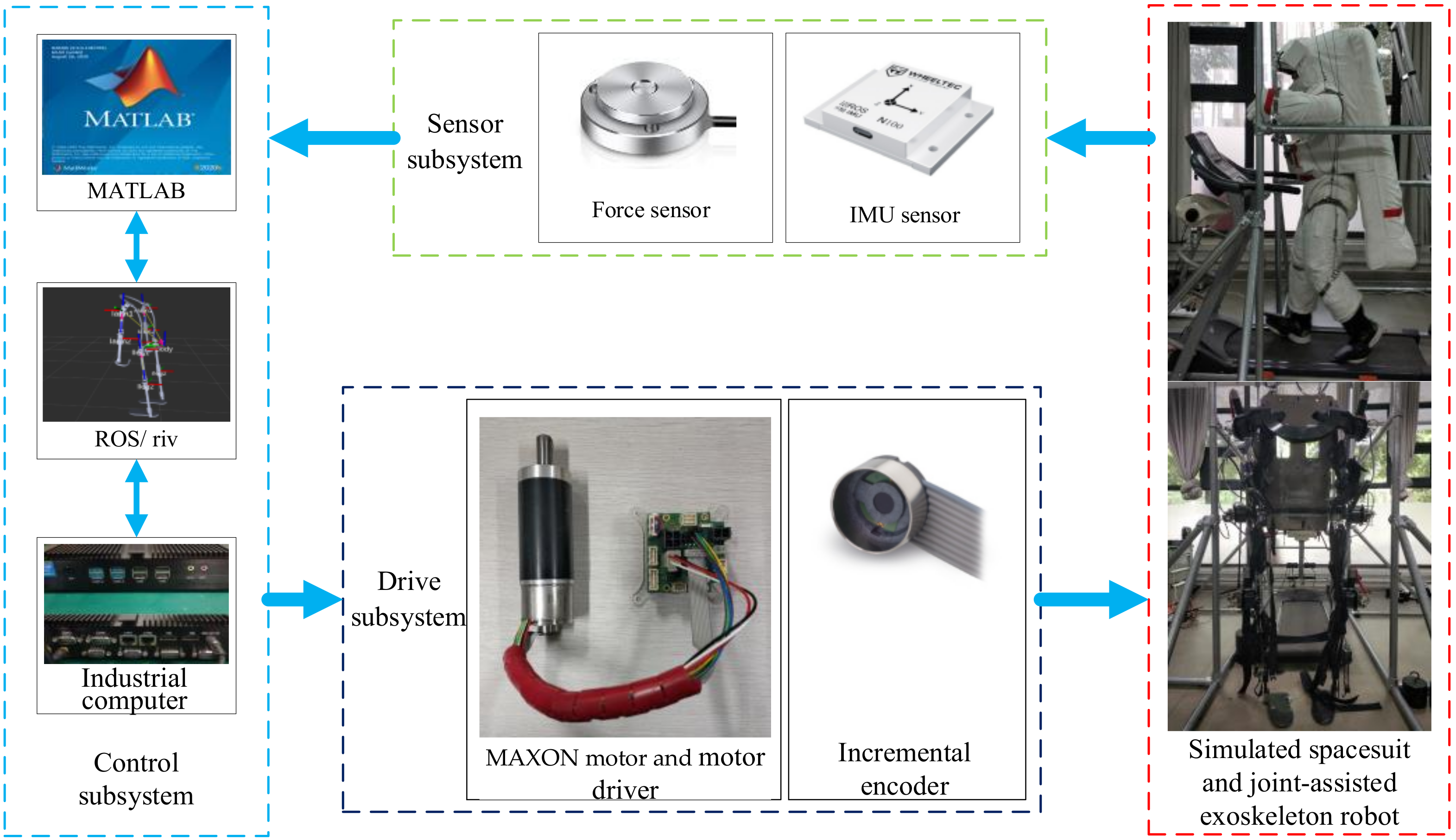
In order to verify the validity of the control algorithm, we established a test platform for an active spacesuit, the structure of which is shown in
Figure 4. The test platform includes a control subsystem, a sensor subsystem, a drive subsystem, a simulated spacesuit, and a joint-assisted exoskeleton robot within an experimental frame. The sensor subsystem mainly collects operational data and uploads them to the control subsystem. For example, some IMU sensors (N100, 400 Hz) collect the wearer’s joint rotation angle in real time, support the ROS system, and use CAN communication; some microforce sensors (AT8104 (Jiangsu, Suzhou, China), 1000 Hz) collect HIS force and communicate with UART; the incremental encoder (EASY (Shanghai, China), 1000 Hz) included with the motor is used to obtain the current motion information of the exoskeleton robot; and the experimenter’s heart rate is measured in real time through the heart rate arm band (POLAR (Kempele, Finland) OH1+). When the heart rate exceeds 150 BPM for 10 s, the test will be suspended and the experimenter will take a full rest. The driving subsystem is mainly used to receive control signals and drive the exoskeleton robot, which consists of eight servo motors (MAXON EC-i series (Sachseln, Switzerland)) and corresponding motor drivers (EPOS4)/incremental encoders (EASY). The control subsystem mainly generates control instructions based on the real-time sensor data and the designed control algorithm, which it loads onto the industrial computer (Intel Core i7-5500U (Santa Clara, CA, USA)) through MATLAB/Simulink 2012b (Natick, MA, USA) and ROS (Robot Operating System) (Ubuntu 20.04 LTS (London, UK)), and outputs the control instructions to the drive subsystem. Since a real extravehicular spacesuit is a high-value piece of equipment, only a simulated spacesuit of similar size can be customized.
4.2. Simulated Lunar Sample Collection Mission
As future EVAs continue to evolve towards planetary surface exploration, the frequency of astronauts’ EVAs will increase, and the tasks will become more complex, placing higher demands on astronauts’ joint mobility. Apart from the typical tasks completed by astronauts during the Apollo moon landing, such as climbing stairs, walking on the moon, and driving a lunar rover, most of the current EVA activities are conducted in low Earth orbit, focusing solely on upper limb movements. Therefore, based on an analysis of typical EVA tasks for astronauts, the EVA task designed in this paper primarily involves collecting samples on the lunar surface. The simulated design of the lunar surface sample collection task is shown in
Figure 5.
The specific process of simulating the lunar surface sample collection mission is as follows: the clothed astronaut walks to the lunar sample according to the command, during which the arm remains in a neutral posture in a low-gravity environment; observes and analyses whether the sample meets the related requirements; adjusts their own posture after confirmation; squats and extends their own arms to grab the sample, and bends their arms to the proper position after picking up the sample; and stands up after adjusting their own posture and maintaining a stable center of gravity, extends their arms, and transfers the sample to the specified position when standing steady. The simulation design of the lunar sample collection mission is in accordance with the mission requirements of astronauts in future low-gravity environments to collect rock specimens and transfer scientific instruments and construction equipment.
In the test environment, the experimenter completed the normal walking (treadmill 3 km/h, 6 min), squatting (treadmill 2 min), and standing up to transfer the sample (treadmill 0 km/h, 2 min, sample mass 10 kg) activities with the joint-assisted exoskeleton robot and the simulated spacesuit. The parameters of the controller were chosen as , , , , , and .
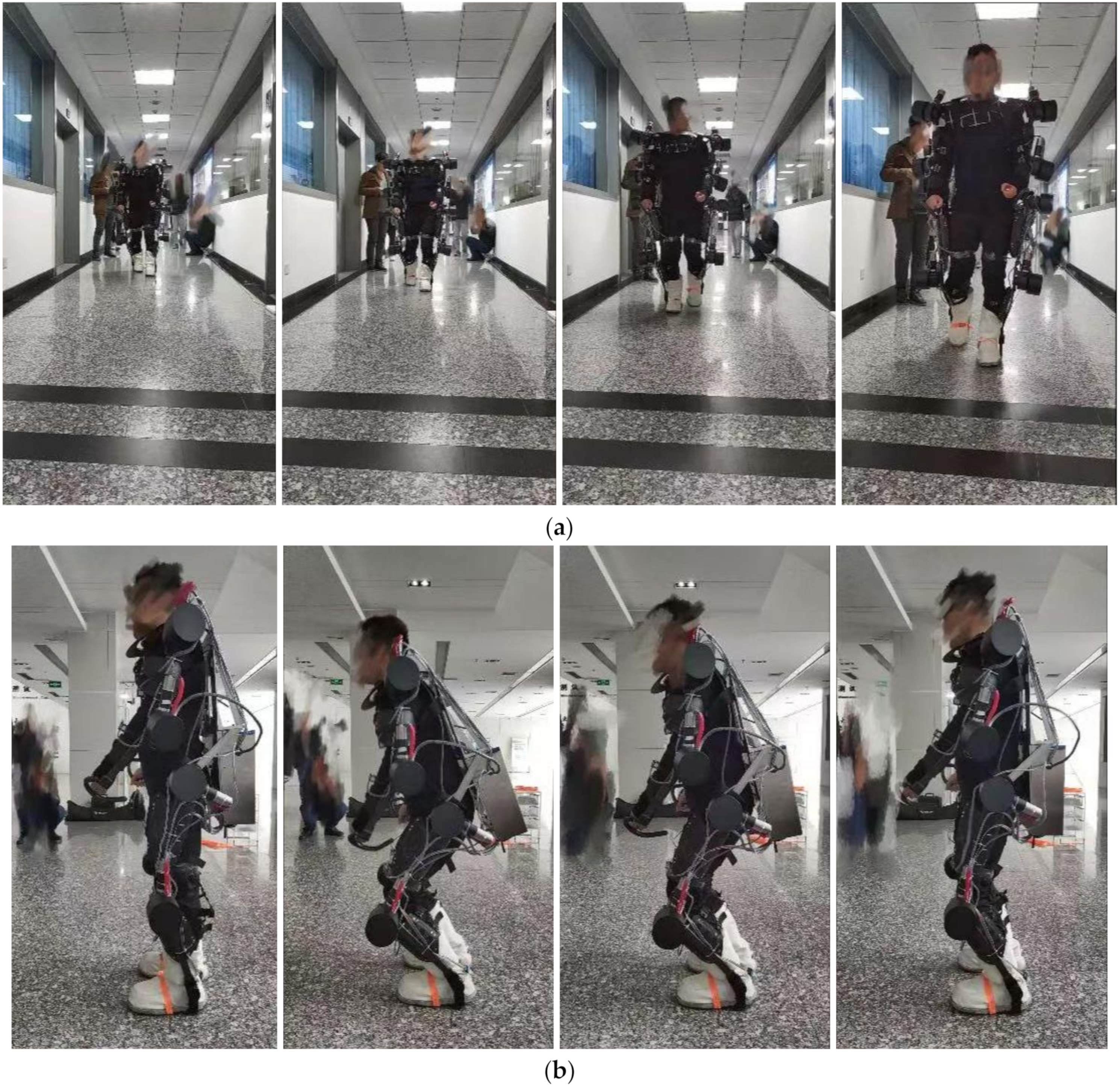
4.2.1. Normal Walking
During the normal walking test, bearing no weight saved the wearer’s physical strength, as shown in
Figure 6.
It can be seen from
Figure 7 that the trajectory tracking effect of the lower limb joints is good, and the HSI force and trajectory tracking errors are gradually reduced. The tracking errors of the lower limb joints
and
are adjusted to achieve a better tracking effect. A small trajectory tracking error leads to a small HSI force and to HSI forces at the thigh interaction of
and the shank interaction of
.
4.2.2. Squatting and Standing Up
During the squatting and standing up test, the wearer is required to wait for their posture to stabilize before continuing to squat/stand up to prevent a fall due to balance problems, as shown in
Figure 8.
It can be seen from
Figure 8 that the trajectory tracking effect of the lower limb joints is good, and the HSI force and trajectory tracking errors are gradually reduced. The tracking errors of the lower limb joints
and
are adjusted to achieve a better tracking effect. A small trajectory tracking error leads to a small HSI force, and the HSI force at the thigh interaction is
while that at the shank interaction is
.
4.2.3. Standing to Transfer the Sample
During the stage of standing to transfer the sample test, a 5 kg barbell is selected as the sample for convenient transfer, and the experimenter passes their hand through the U-ring and uses the upper limb exoskeleton robot to carry the sample, as shown in
Figure 9.
It can be seen from
Figure 8 that the trajectory tracking effect of the upper limb joints is good, and the HSI force and trajectory tracking errors are gradually reduced. The tracking errors of the upper limb joints
and
are adjusted to achieve a better tracking effect. A small trajectory tracking error leads to a small HSI force, and the HSI force at the upper arm interaction is
while that at the lower arm interaction is
.
4.3. Overall Power-Assisted Efficiency
The most effective index for evaluating the efficiency of the joint-assisted exoskeleton robot is through the metabolic energy consumption during the simulated lunar sample collection mission. In reference [
23], there is a relationship between energy metabolism and heart rate when engaging in moderate intensity physical activity. Statistical analysis shows that the correlation equation between the two is
where
is the heart rate and
is the oxygen consumption.
In addition, according to the experimental results, it is found that the limit of normal physical activity intensity is when the heart rate reaches 150 beats per minute (BPM) or oxygen consumption is 1.36 L/min. After exceeding this limit, oxygen consumption will no longer increase with the increase in heart rate. Therefore, the experimenter’s heart rate is measured in real time through the POLAR OH1 + heart rate arm band. When the heart rate exceeds 150 BPM for 10 s, the test will be suspended and the experimenter will take a full rest.
In the test of standing to transfer 5 kg and 15 kg barbells, the heart rate values of the three experimenters when wearing the nonworking active spacesuit and when wearing the working active spacesuit were collected. During the test, in order to avoid the boredom caused by repetitive exercise and the heart rate exceeding 150 BPM, the duration of each test was required to be 5 min, and the oxygen consumption and heart rate data after the first minute and the last minute were removed as valid data; 10 groups of data were tested. Next, the oxygen consumption of the experimenters was obtained according to Equation (40), as shown in
Table 2.
According to the results in
Table 2, with the increase in the mass of the transferred barbells, the oxygen consumption of the three experimenters increased in both wearing states, which is in line with the actual situation. Secondly, the addition of the joint-assisted exoskeleton reduced the oxygen consumption of the experimenter; the maximum value was 15.88% of the 15 kg barbells transferred by experimenter 3, which was mainly due to the better trajectory tracking effect. Finally, the results of the oxygen consumption test showed a strong relationship with the physical ability of the experimenter.


