Article

Obstacle Avoidance Path Planning for UAV Applied to Photovoltaic Stations Based on Improved Dynamic Window Method

School of Mechanical Engineering, University of Science and Technology Beijing, Beijing 100083, China
*
Author to whom correspondence should be addressed.
Electronics 2025, 14(10), 1963; https://doi.org/10.3390/electronics14101963
Submission received: 11 April 2025 / Revised: 2 May 2025 / Accepted: 8 May 2025 / Published: 12 May 2025

Abstract

:
In order to solve the problem of obstacle avoidance and low endurance of UAV autonomous flight in column obstacle scenes such as transmission towers, this paper improves and integrates the path planning algorithm to achieve efficient and accurate path planning in unstructured and unknown dynamic environments in column scenes. An improved DWA algorithm is proposed to improve the obstacle avoidance effect by adaptively improving the evaluation function and increasing the relevant evaluation function. At the same time, a hybrid path planning method in the obstacle scene of the UAV column is proposed. Firstly, the improved A* algorithm is used for global optimal planning. The UAV moves along the global optimal path, performs local dynamic perception at the same time, and calls the improved DWA algorithm to complete real-time obstacle avoidance and local replanning. Finally, the effectiveness and applicability of the improved DWA algorithm are verified by designing simulation experiments in different scenarios. The improved DWA algorithm is superior to the traditional DWA algorithm in terms of path length, running time, minimum safe distance, and number of iterations. The path length is reduced by 23.92%, the running time is reduced by 33.23%, and the number of iterations is reduced by 22.57% in the complex environment. At the same time, the simulation experiment of unknown obstacle avoidance for a photovoltaic scene in the area of transmission tower erection and the simulation experiment of path planning for UAV column obstacle scene in ROS environment are completed, which verifies that the hybrid algorithm has good robustness and environmental adaptability.

1. Introduction

Multi-rotor UAVs (unmanned aerial vehicles) have shown great potential in the inspection and maintenance of photovoltaic power plants [1] and the cleaning of photovoltaic modules [2] due to their excellent hovering, moving, and handling performance. At the same time, they can efficiently perform pesticide spraying, monitoring, and forestry resource protection tasks in agriculture and forestry [3]. Moreover, they can flexibly cover a large area and complete precise operations, significantly improving the efficiency and safety of operation and maintenance, which is of great significance for promoting the economic and sustainable development of solar energy utilization, agricultural production, and forestry management. However, when the UAV performs actual tasks, it often encounters different types of obstacles. How to achieve a fast response to the surrounding environment, a smooth and energy-saving obstacle avoidance mechanism, is crucial to reducing the risks in the operation process [4]. Therefore, path planning technology is particularly important for UAV autonomous navigation. This paper focuses on the related content of autonomous flight obstacle avoidance of UAV in column obstacle scenes (relatively densely distributed columns with similar diameters above and below, such as photovoltaic scenarios with transmission towers). Path planning is divided into global and local planning. Global planning relies on the complete environment map, while local planning requires real-time perception of the environment [5]. The related algorithms include graph search, linear programming, intelligent optimization, reinforcement learning, and so on [6].

1.1. Global Path Planning

Global path planning usually uses more traditional RRT (rapidly-exploring random tree) [7], ant colony optimization [8], A* [9], Dijkstra [10], and other algorithms. These algorithms improve the efficiency of path search and achieve the asymptotic optimization of the path to a certain extent. However, the smoothness of the path is not well covered, and there are obvious deficiencies in the face of complex, unknown environments. The traditional A* algorithm combines the advantages of uniform cost search and greedy search to ensure the optimal path, which is the most widely used, but the search time is long and the efficiency is low. Therefore, how to further improve the performance of the A* algorithm in various application scenarios is an important issue that current scholars need to solve for global path planning.
In view of the above situation, some scholars have proposed new path search strategies or selected nodes to be expanded according to prescribed methods to improve search efficiency and optimize paths. Ju et al. [11] proposed an improved A* algorithm to solve the problem that the traditional A* algorithm generates a non-shortest path under certain conditions. By connecting the straight line segments of the starting point and the end point, the algorithm transforms the obstacles passing through the path into a circular area and solves the intersection point, and then merges the adjacent intersection segments to generate a shorter path. The results show that the algorithm is suitable for scenarios with high path length requirements but low real-time requirements. Li et al. [9] proposed an improved A* algorithm, which added several constraints to plan a safer and more realistic flight path according to the operation characteristics of the four-axis UAV in the mountain environment. It has better real-time performance and global optimal solution ability. Gao et al. [12] proposed a sub-node expansion method of the A* algorithm to eliminate boundary collision accidents, and improved the evaluation function to make the generated UAV route more efficient. Zhou et al. [13] improved the evaluation function by using the cubic uniform B-spline interpolation method to smooth the turning points in the path. The experiment proves that the improved A* algorithm is feasible. He et al. [14] proposed an automatic switching neighborhood search algorithm to improve the A* algorithm, which avoids the calculation of a large number of intermediate nodes in the pathfinding process of the A* algorithm and effectively reduces the cost in the pathfinding process. Shi et al. [15] improved the evaluation function for the defects of the A* algorithm and improved the planning efficiency, but the planned path was still close to the obstacle.
Another part of scholars’ focus is on the cost estimation function of the traditional A* algorithm and proposes related improvements to improve the search efficiency of the algorithm. Aiming at the problem that the traditional A* algorithm has slow search speed and many redundant nodes in complex environment, Yan et al. [16] By optimizing the heuristic function, introducing the adaptive step size strategy, and dynamically adjusting the bidirectional A* search step size, the comprehensive requirements of global planning and real-time obstacle avoidance are realized. Aiming at the problem that the traditional A* algorithm has slow search speed and many redundant nodes in the face of complex environment and high dynamic tasks, Tang et al. [17] adopted the bidirectional search mechanism and set the weight coefficient optimization heuristic function to comprehensively consider the global planning and real-time obstacle avoidance requirements. Aiming at the problems of poor real-time performance, a large amount of calculation, and serious memory consumption of the traditional A* algorithm in three-dimensional path planning, Hu et al. [18] optimized the heuristic function of the A* algorithm and improved the search efficiency. Li et al. [19] improved the traditional A* algorithm by using the piecewise evaluation function with dynamic heuristic and weighted processing, the steering cost heuristic function based on heading angle deviation control, the redundant turning point removal strategy and the quasi-uniform cubic b-spline, aiming at the problems of too many traversal nodes, too many redundant corners, too large turning angle and unsmooth generating path in the path planning of the traditional A* algorithm, and confirmed the applicability of the improved A* algorithm in the real world.

1.2. Local Path Planning

Local path planning usually uses artificial potential field [20], DWA (dynamic window approach) [21], TEB (time-elastic band) [22], and other algorithms. The artificial potential field method is a local path planning algorithm based on a virtual force field. The principle is that the robot’s working space is regarded as a potential field, and the target point generates a gravitational potential field to attract the robot to approach. Obstacles generate a repulsive potential field to prevent the robot from approaching. The direction of motion of the robot is determined by calculating the resultant force. However, the artificial potential field method also has some limitations, such as being prone to fall into local optimal solutions, which may lead to oscillation phenomena in complex environments, etc. DWA algorithm is a local path planning algorithm based on dynamic speed sampling. The principle is to generate a set of feasible motion trajectories under the current speed constraint of the robot, and select the optimal path through the evaluation function. Specifically, the algorithm first determines the velocity search space (dynamic window) according to the kinematic and dynamic constraints of the robot, and then samples different combinations of linear velocity and angular velocity in the window to simulate the trajectory in a short time in the future. Each trajectory is scored according to indicators such as target proximity, obstacle avoidance ability, speed, and smoothness, and finally, the optimal speed command is selected to control the robot’s movement. The DWA algorithm also has many limitations. For example, it is easy to fall into a local optimal solution, and it may not be able to find a feasible path in a complex obstacle environment. The ability to predict dynamic obstacles is weak, and it is difficult to deal with suddenly moving objects; the weight of the evaluation function depends on manual adjustment, and different scenarios need to be re-adjusted. In addition, this algorithm is only suitable for local planning in a short time, and it needs to rely on the global planner to provide the initial path. The TEB algorithm is a local path planning algorithm based on space–time optimization. The principle is to model the trajectory of the robot as an elastic band with time information. The shape and time distribution of the elastic band are continuously adjusted by the optimization algorithm, so that the robot can reach the target position efficiently and safely. The algorithm will comprehensively consider multiple optimization objectives such as path length, motion time, obstacle avoidance distance, and motion smoothness, and finally generate a space–time optimal motion trajectory. However, the optimization results of the TEB algorithm depend on the initial trajectory quality. In a complex environment, it may fall into a local optimal solution; limitations such as limited real-time response to dynamic obstacles may occur.
Due to the increasing complexity of the application environment and working scenarios, a certain path planning method alone is often unable to meet the requirements of UAV autonomous navigation. Aiming at this problem, scholars combine the advantages of global planning and local planning through the idea of hybrid path planning to solve the problems of poor real-time performance, non-optimal path, and easy to fall into local optimum in path search. Yan et al. [23] combined the AHP (Analytic Hierarchy Process) to calculate the value of the weight factor in the dynamic window algorithm, and established a self-feedback mechanism between the weight factor and the environmental factor, which optimized the safety, driving time, and path length. Jiang et al. [24] proposed a path planning algorithm for mobile robots based on a velocity sampling strategy, which integrates direction information and distance information, aiming at the problems of difficult selection of optimal trajectory, unsmooth path, and poor robustness of the traditional DWA algorithm. Compared with the traditional algorithm, the running time is short, the number of iterations is small, and the trajectory is smoother. Aiming at the problem that it is difficult to take into account the safety, economy and smoothness of USV (unmanned surface vehicle) collision avoidance due to the changeable motion state of obstacles in complex environment, Han et al. [25] proposed a USV collision avoidance method combining dynamic window method and DDPG (deep deterministic policy gradient), and designed a local guidance method based on dynamic window method. The path planned by this method is more reasonable, smooth, and less risky. Xiong et al. [26] proposed an improved DWA algorithm with adaptive parameter adjustment to solve the problems that the DWA algorithm is prone to fall into a local optimum, the path smoothness is not high, and the adaptability to the environment is low. The experimental results show that the improved DWA algorithm improves the performance of the algorithm and can effectively avoid collisions and generate faster, shorter, and smoother paths.
However, the path planning effect of the traditional DWA algorithm depends on the coordination of the weight coefficients of each part of the evaluation function. Otherwise, it will lead to the inability to avoid obstacles and narrow areas and deviate from the target point. In view of the above problems, Li et al. [27] proposed a method combining the improved A* algorithm and DWA. This fusion algorithm can ensure a smoother and shorter global optimal path and can effectively avoid surrounding dynamic obstacles. Aiming at the problem of four-axis UAV path planning in an indoor environment, Li et al. [28] proposed a path planning method based on an improved fusion algorithm. This method introduces indoor hybrid constraints and uses dynamic weights to reconstruct the evaluation function of the traditional A* algorithm. The neighborhood search method is adjusted adaptively according to the direction angle of different map areas, and the safety radius is set to consider the actual size of the UAV. By integrating the improved A* algorithm and the improved DWA algorithm, the indoor autonomous path planning and obstacle avoidance are realized. Jiang et al. [29] proposed an optimized fusion strategy based on the A* algorithm and the DWA algorithm to solve the problem that it is difficult to achieve global path optimization and dynamic obstacle avoidance simultaneously by using the A* or the DWA algorithm alone. The distance adaptive coefficient is introduced to optimize the evaluation function of the DWA algorithm, which improves the performance of local path planning. The key nodes in the global path generated by the optimized A* algorithm are used as the temporary target points of the DWA algorithm for path planning, so as to achieve both global path optimization and real-time obstacle avoidance. Ma et al. [30] proposed a path planning algorithm that integrates an improved A* algorithm and a dynamic window method (DWA). The improved A* algorithm is optimized in terms of path length and turning angle. After integrating the improved dynamic window method, the mobile robot can find the shortest barrier-free path in a complex environment, avoid unknown obstacles in real time, and reach the target point safely.
Recent progress in dynamic obstacle avoidance: Integration of deep reinforcement learning and classical algorithms. The fusion of deep reinforcement learning with conventional algorithms has become a research hotspot in dynamic obstacle avoidance, with core challenges focusing on balancing algorithmic efficiency, environmental adaptability, and engineering feasibility. Addressing path planning limitations for quadrotor UAVs, Zhao et al. [31] proposed an offline reinforcement learning control framework that establishes an environment-independent data-driven paradigm. By incorporating pessimistic estimation strategies, this method reduces the impact of dataset uncertainty during learning, demonstrating better generalization capabilities than traditional online reinforcement learning in dynamic obstacle scenarios, thereby providing a safer learning architecture for industrial applications. Extending this work, Wang et al. [32] addressed the high real-time requirements for fixed-wing UAV 3D navigation by integrating LSTM networks into an interferential fluid dynamics system (IFDS). Their approach leverages temporal features to optimize path parameter generation, achieving the following experimental results: path length deviation remains below 5% of the theoretical optimum, trajectory tracking errors stay within 0.3 m using backstepping controllers, and single-planning time requires only 8 milliseconds. For multi-objective optimization in complex environments, Suresh et al. [33] developed a cross-modal fusion method. They employed an adaptive beetle swarm Levy flight optimization (BSLFO) algorithm to optimize path smoothness metrics, while constructing a fuzzy rule-driven deep neural Network (FRDNN) for dynamic obstacle situational awareness. MATLAB simulations validated a 98.62% obstacle avoidance success rate, demonstrating significant advantages in planning efficiency and accuracy over existing methods.

1.3. Cooperative Obstacle Avoidance for Multi-UAV Systems

With the advancement of swarm UAV applications, cooperative multi-agent path planning has become a key research focus in recent years. Current studies exhibit dual trends of algorithmic integration and scenario specialization. For cooperative obstacle avoidance in complex environments, Ni et al. [34] proposed an A-biobjective dynamic window approach (A-BDWA), which constructs a three-dimensional evaluation function incorporating heading angle, obstacle distance, and line-of-sight constraints. In dual-UAV cooperative scenarios, this method achieves an 88.3% mission completion rate with optimal flight time, while maintaining the impact of weight fluctuations on flight time below 5%, thereby validating the robustness of their multi-objective optimization framework. Zhao et al. [35] innovatively developed a distributed decision-making model with shared experience pools based on deep reinforcement learning, departing from traditional control paradigms. By reconstructing reward functions, their approach enables the simultaneous execution of obstacle avoidance, target tracking, and containment tasks. The integrated environmental perception mechanism enhances swarm coordination accuracy by 23% in dynamic obstacle scenarios. Addressing formation obstacle avoidance in unknown environments, Wang et al. [36] combined 3D-VFH+ with an improved dynamic window approach (DWA). Through the introduction of rotational cost functions and dynamic weight factors, their method improves formation trajectory smoothness by 41% and reduces path conflict rates by 67% compared to conventional DWA algorithms, providing a new technical pathway for cooperative operations in dense obstacle environments.
In summary, although existing path planning algorithms can achieve autonomous navigation in specific scenarios, they demonstrate limited adaptability and robustness across diverse environments. Despite recent significant advancements in deep learning methods and multi-agent cooperative strategies, persistent challenges remain in specialized scenarios like photovoltaic power stations: dense static obstacles cause dramatic efficiency degradation in traditional search algorithms, the stochastic motion patterns of dynamic obstacles (e.g., bird flocks) exceed the predictive capabilities of conventional models, and communication latency coupled with decision conflicts in multi-UAV coordination require urgent resolution.
To address these challenges, this paper proposes a novel hybrid path planning algorithm tailored for the dynamic and complex transmission tower–photovoltaic station environment, by integrating the strengths of an improved A* algorithm [19] and a modified DWA (dynamic window approach) algorithm. The main contributions of this work are as follows:
(1)
An improved DWA algorithm is proposed, which optimizes the path planning process by considering the physical dimensions of the UAV for obstacle inflation, introducing adaptive weight adjustment mechanisms, and incorporating a global distance evaluation sub-function. These enhancements improve the algorithm’s adaptability, real-time performance, and obstacle avoidance capability across various environments, resulting in shorter, smoother paths that are closer to the global optimum.
(2)
A novel hybrid path planning algorithm is developed by combining the improved A* algorithm with the modified DWA algorithm specifically for the photovoltaic station environment. The global planner leverages the improved A* algorithm to generate an initial optimal path, while the local planner dynamically adjusts the trajectory in response to real-time environmental information using the modified DWA algorithm, thereby ensuring safe and efficient UAV flight in complex environments.
(3)
Extensive simulation experiments under various scenarios have been conducted to comprehensively validate the effectiveness, applicability, and robustness of both the improved DWA algorithm and the hybrid path planning algorithm. Results show that the improved DWA algorithm outperforms traditional methods in key metrics such as path length and runtime, while the hybrid algorithm demonstrates reliable path planning and obstacle avoidance capabilities in complex environments with column-like obstacles.

2. Materials and Methods

In this paper, an improved DWA algorithm is proposed to enhance the obstacle avoidance effect by adaptively and dynamically adjusting the evaluation function. Furthermore, combined with the improved A* algorithm [19], a hybrid path planning method is proposed to ensure the global optimal path acquisition and solve the unknown dynamic problem of the transmission tower-photovoltaic scenario. Performance simulation experiments show that the improved DWA algorithm is superior to the traditional algorithm. In order to verify the effectiveness of the hybrid method, the simulation experiments of obstacle avoidance and ROS (robot operating system, Kinetic Kame) UAV(Bobei Technology Co., Ltd., Chengdu, China) path planning were carried out.

2.1. Improved A* Algorithm

The path search performance of the traditional A* algorithm is affected by the heuristic function and produces different effects. If the value of the estimated cost h(n) is much smaller than the value of the actual cost g(n), the total cost function f(n) mainly depends on g(n). At this time, the A* algorithm is biased towards the Dijkstra algorithm. The path search traverses a large number of nodes, and the convergence speed of the algorithm is slow. The search efficiency is low, but it can ensure that the optimal path is obtained; on the contrary, if the estimated cost h(n) is much larger than the actual cost g(n), the A* algorithm evolves into the Best-First-Search. At this time, the algorithm traverses fewer nodes and can quickly find a collision-free path, but it cannot guarantee the global optimum [37]. Therefore, this paper uses the improved A* algorithm [19] to assign parameterized weights to the actual cost and heuristic cost of the cost estimation function of the A* algorithm, and determines the value of the parameterized weights according to the application scenario to achieve a more efficient search for the global optimal path.
The specific weight setting adopts the method of fuzzy control. According to the environmental characteristics of the photovoltaic power station and the flight requirements of the UAV, the path planning is divided into two stages: preliminary exploration and precise optimization. In the preliminary exploration stage, in order to quickly locate the target area, the weight of the heuristic cost function is set to 0.7, and the weight of the actual cost function is set to 0.3, so that the algorithm preferentially explores the direction close to the target. When entering the precise optimization stage, in order to ensure the safety and optimality of the path, the weight of the heuristic cost function is adjusted to 0.3, and the weight of the actual cost function is adjusted to 0.7, with a focus on considering the actual cost and safety of the path. In this way, efficient path planning in different stages can be achieved.

2.2. Improved DWA Algorithm

DWA Algorithm is an advanced strategy for UAV path planning. According to the physical constraints and environmental information of UAV, the speed combination (v, w) in each motion simulation cycle is sampled within the acceptable range of speed, and the potential trajectory of different speed combinations in the future is predicted. The speed combination (vbest, wbest) of the optimal path is determined by the evaluation function to achieve local path planning to the target point. The traditional DWA algorithm has the problems of inaccurate path planning and poor adaptability because it does not consider the actual size of the UAV and the fixed weight of the evaluation function. To solve these problems, this paper proposes an improved DWA algorithm. The DWA algorithm is improved by considering the size of the UAV and expanding the obstacles, as well as dynamically adjusting the evaluation function and increasing the evaluation item and its weight of the distance between the simulated trajectory and the global target. These improvements make the algorithm more adaptable to different point density maps. The adaptive dynamic adjustment weight factor can adjust the speed weight according to the point density. The global distance evaluation sub-function can guide the UAV to quickly find the target, reduce the computational complexity, and make the improved DWA algorithm more accurate in path planning. The flexibility of the algorithm can generate a shorter, smoother, and closer to the global optimal path.

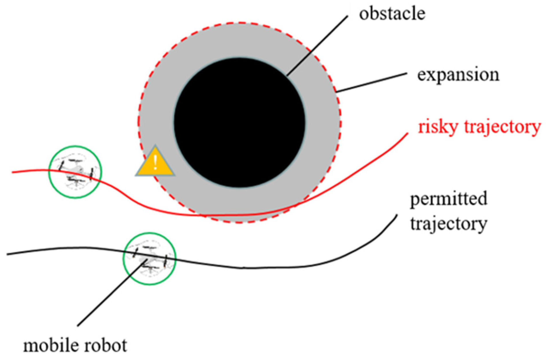
2.2.1. Obstacle Expansion Treatment

Figure 1 shows a schematic diagram of the expansion process. The mobile robot is approximately regarded as a circle, and the expansion range of the obstacle must be greater than or equal to the radius of the robot. At this time, the mobile robot can be regarded as a particle. The larger the expansion, the smaller the probability of collision between the generated path and the obstacle, but it will increase the path length and the turning angle, which can be adjusted according to the actual application requirements. In actual path planning, although intuitively, the greater the amount of expansion, the smaller the probability of collision between the generated path and the obstacle, but this does not mean that the path length will increase. In fact, in the complex column obstacle scene (such as the transmission tower–photovoltaic scene), the distribution of obstacles is relatively dense. Without expansion processing, when the UAV flies close to the unamplified obstacle, it may need to frequently make a large turn to avoid obstacles, which will lead to an increase in the overall length of the path, a large fluctuation in the heading angle, and poor flight stability. After the obstacle expansion processing, the UAV can consider the safe distance between its own size and the obstacle in advance when planning the path. Through the optimization algorithm, a relatively smooth and stable path can be planned. Although in the local area, the path may be rounded off by avoiding the expanded obstacles, from the perspective of the overall path, by reducing unnecessary steering and adjustment, the path length can be effectively shortened, and the safety and stability of the flight can be improved. In addition, combined with other optimization measures in the improved DWA algorithm, such as adaptive dynamic adjustment of the weight factor and increasing the global distance evaluation sub-function, the UAV is further guided to fly efficiently towards the target point, and the shorter path planning is realized under the premise of ensuring the safe distance. Therefore, considering various factors in complex scenarios, obstacle expansion processing helps to achieve shorter path planning while improving safety.
In the actual photovoltaic power station, the size of the UAV and the safe distance from obstacles such as transmission towers are the key factors in determining the inflation amount. Taking the UAV used in our research as an example, its radius is r. Considering factors such as airflow interference and positioning errors during flight, to ensure safety, we set the obstacle inflation amount to 1.5r. In this way, it can effectively prevent the UAV from colliding with obstacles, and at the same time, it will not cause excessive increases in the path length and turning angle due to an overly large inflation amount, ensuring the rationality and efficiency of path planning.

2.2.2. Adaptive Dynamic Adjustment of Weight Factors

Focussing on the lack of environmental adaptability of the traditional DWA algorithm, this paper introduces the azimuth adaptive dynamic adjustment factor αd based on the distance of the target point and the speed dynamic adjustment factor γs based on the complexity of the obstacle. αd increases as the robot moves away from the target, guiding it forward; when it is close to the target, the influence on the evaluation function is weakened. The speed weight factor γs decreases when obstacles are dense, and the robot decelerates to maintain a safe distance; increases when there are fewer obstacles, allowing the robot to quickly avoid obstacles and move forward. The specific calculation principle is as follows.
α d = α min + α max α min d 0 d g ζ , α d < α max α max , α d > α max
γ s = γ min + 1 M x g x n + 1 y g y n + 1 D min R W κ , D min R W γ max , D min > R W
In Equation (1), αmin and αmax are the minimum and maximum azimuth weights, d0 is the Euclidean distance between the starting point and the target position, dg is the Euclidean distance between the end point of the current predicted trajectory and the target position, and ζ is the exponential factor. In Equation (2), γmin and γmax are the minimum and maximum speed weights, (xg, yg) and (xn, yn) are the coordinates of the target position and the end coordinates of the current predicted trajectory. M is the area of the obstacle, Dmin is the minimum distance between the robot and the nearest obstacle, RW is the detection radius of the rolling window, and κ is the exponential factor. These parameter values are determined by conducting simulation analyses of photovoltaic power station environments with different levels of complexity and combining them with the dynamic performance of the UAVs. This is done to ensure that the algorithm can make reasonable decisions in various environments.

2.2.3. Global Distance Evaluation Subfunction

goal(v, w) is the introduced global distance evaluation sub-function, which aims to guide the robot to move in the direction of the target position and shorten the distance between the robot and the target point. The evaluation sub-function cost calculation method is as follows:
g o a l ν , w = d 0 ( x n x g ) 2 + ( y n y g ) 2
In the above equation, (xn, yn) is the coordinates of the end point of the current predicted trajectory; (xg, yg) is the global target point position coordinates.
In summary, the improved DWA algorithm evaluation function can be obtained as follows:
G ν , w = σ α d · h e a d i n g ν , w + β · d i s t ν , w + γ s · v e l ν , w + δ · g o a l ν , w
where δ is the weight coefficient of the global distance evaluation sub-functions. The value of the weight coefficient δ of the global distance evaluation sub-function has an important influence on the performance of the algorithm. Through multiple simulation experiments and comparisons, in the scenario of the photovoltaic power station, we set δ to 0.5. When the value of δ is too small, the guiding effect of the algorithm on the target direction is not obvious, which may lead to the path planning deviating from the target. When the value of δ is too large, the algorithm pays too much attention to the target distance, causing the path planning to ignore other important factors, such as the safe distance from obstacles. Setting δ = 0.5 can guide the UAV to move towards the target while comprehensively considering other evaluation factors, ensuring the accuracy and safety of path planning.

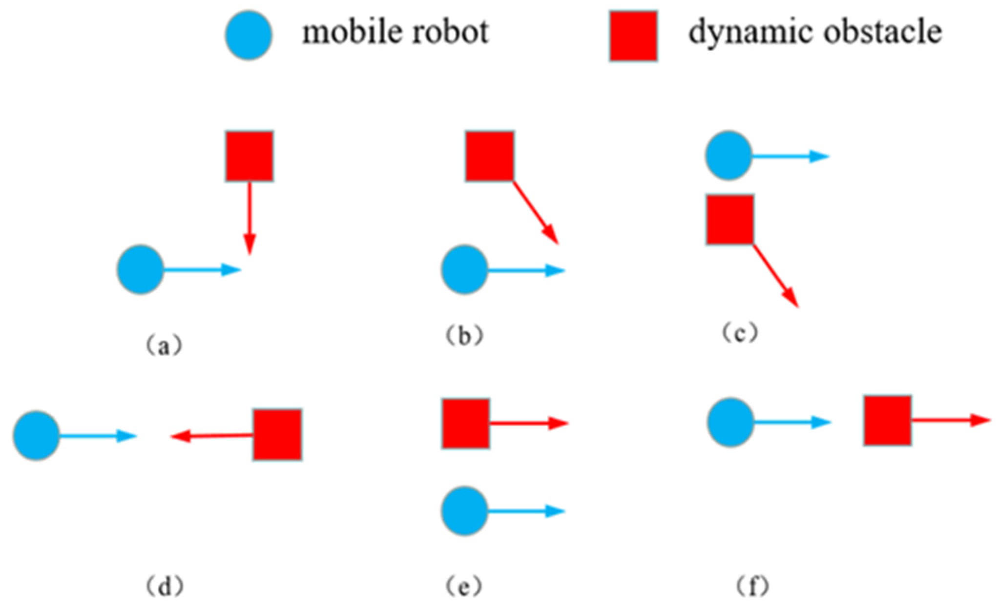
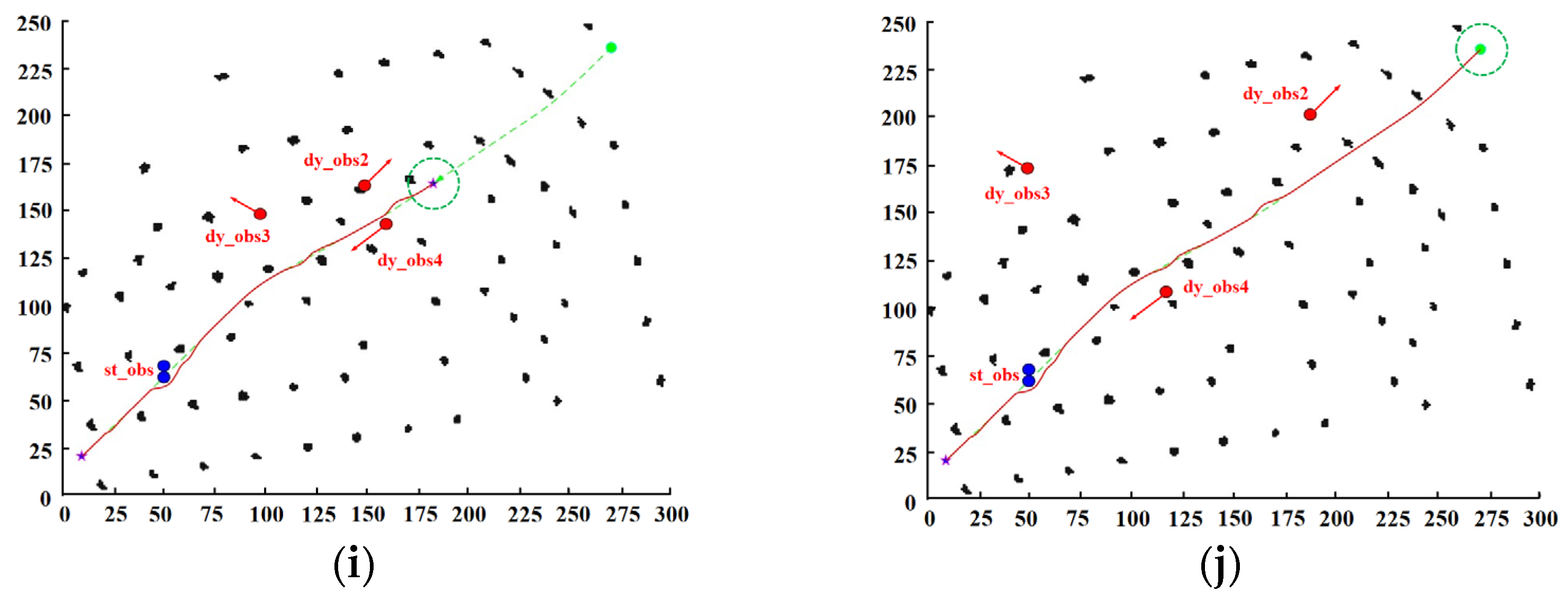
2.2.4. Dynamic Obstacle Prediction and Avoidance Strategy

When the robot encounters the interference of dynamic obstacles, it is necessary to predict the relative trajectory of the two according to the direction of its own motion and the direction of motion of the dynamic obstacles in a simulation cycle, to determine whether it will intersect at a certain time and lead to collision, and then take corresponding avoidance measures [38]. The analysis of the specific movement is shown in Figure 2.
As shown in Figure 2a,b above, the robot and the dynamic obstacle may collide due to their different relative motion directions. It is necessary to calculate the time when the two reach the intersection point and the difference Δt and the time limit Δt0 to determine whether a collision occurs. The specific calculation needs to consider the diameter Dr and Do of both sides, the distance dr and do of the two to the intersection of the trajectory, and the travel speed vr and vo. The calculation formula is as follows:
Δ t = d r v r d o v o
Δ t 0 = m a x D r / v r , D O / V O
According to the above equation, in order to avoid dynamic obstacles smoothly, the mobile robot needs to meet: Δt > Δto, otherwise collision will occur. If the collision possibility is predicted by calculation, the accelerated passing or in-situ waiting strategy is called to avoid obstacles according to the specific situation.
When the relative motion trajectory between the mobile robot and the dynamic obstacle is shown in Figure 2c,e above, the two trajectories do not intersect, so there will be no collision behavior. When the two are in the motion state shown in Figure 2d, the two trajectories are in direct conflict and must collide. At this time, the robot needs to use the DWA algorithm to plan the obstacle avoidance path in advance. When the motion state of the two is shown in Figure 2f, the trajectory of the two coincides in the plane. At this time, it is necessary to determine the farthest intersection position of the trajectory under the current rolling window, and then use the above method to determine whether a collision occurs.

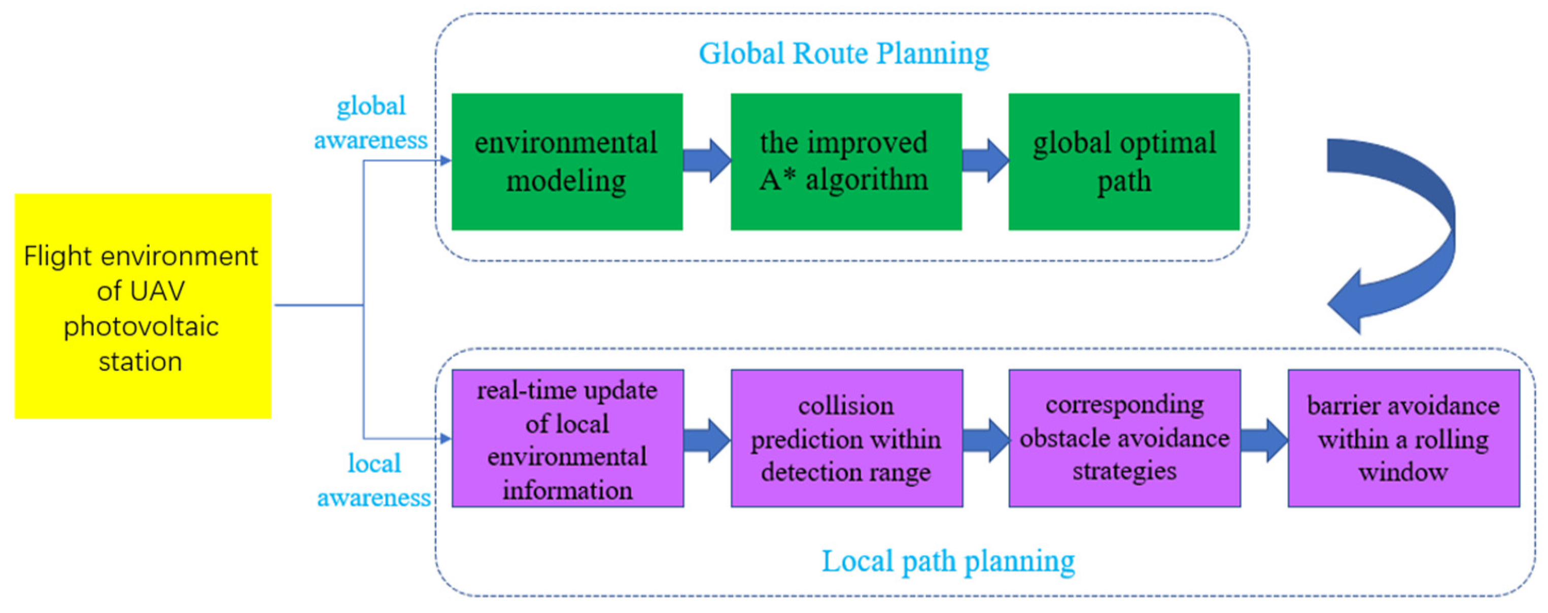
2.3. Hybrid Path Planning of UAV Photovoltaic Station Based on Improved A* Algorithm and Improved Dynamic Window Method

This paper combines the improved A* and DWA algorithms, and proposes a hybrid path planning method, which aims to efficiently obtain the global optimal path while dealing with unknown dynamic challenges in the photovoltaic station environment. Before the flight of the UAV, if the environment is unknown, the improved DWA algorithm is used to plan the local path in real time. If the environment is known, the improved A* algorithm is used to pre-plan the global path. The UAV flies along this path, updates the environmental information in real time, predicts and avoids obstacles, and continues to move along the global path after obstacle avoidance until it reaches the target. In hybrid path planning, the improved A* algorithm can quickly plan the global path at different point density maps and reduce search redundancy. In the local planning of the improved DWA algorithm, in the face of different point density environments, it can use its own improvement mechanism to respond flexibly and ensure the stable flight of the UAV. The overall framework is shown in Figure 3.

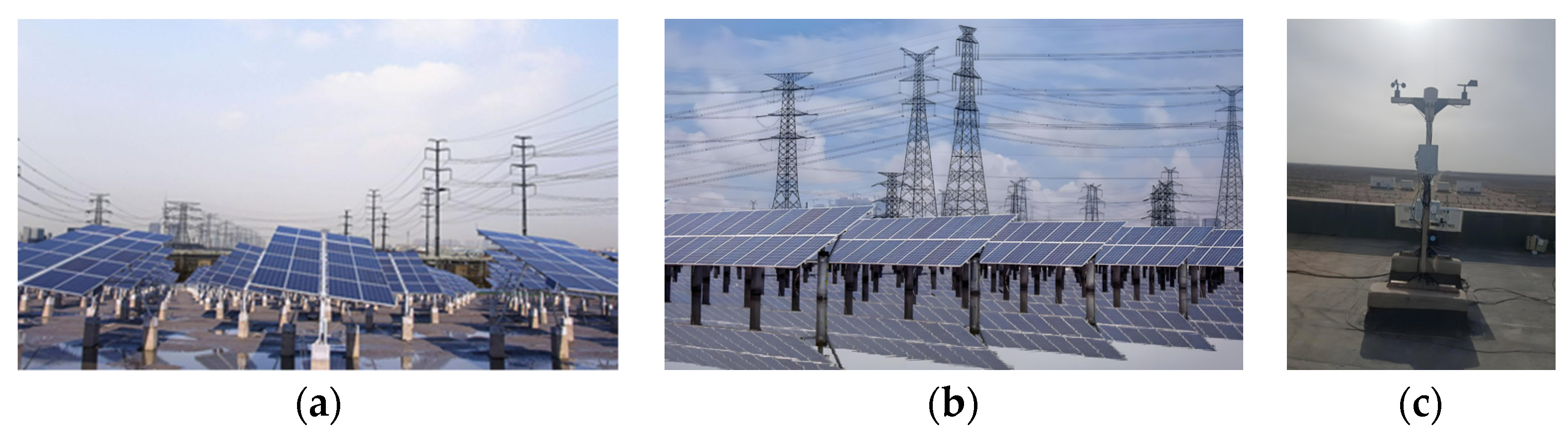
2.4. Simulation Verification of Hybrid Path Planning Method Based on Transmission Tower-Photovoltaic Scene Map

In order to verify the adaptability and effectiveness of the improved DWA algorithm in different environments, this paper uses Matlab r2022a software to construct two kinds of obstacle maps with different complexity, and carries out two sets of simulation experiments under static and dynamic different scenarios. The first group of experiments is the comparison of the two maps in the static environment. The second group of experiments is to add mobile obstacles on the basis of the static environment map to compare the dynamic obstacle avoidance effect of the improved algorithm.

2.5. Simulation Verification of Hybrid Path Planning Method Based on Plantation Map

In order to verify the effectiveness of the proposed hybrid path planning method, this section uses the two-dimensional grid map transformed from the field-collected transmission tower-detection station-photovoltaic scene point cloud data as a real environment map, and performs simulation experiments and verification of unknown static and dynamic obstacles on Matlab r2022a. The photovoltaic station area used in the experiment is located in the shallow beach of Zhanhua Lingang Industrial Park in Binzhou City. The collected three-dimensional point cloud map consists of 71 transmission towers and detection station components. The circumference of the whole area is about 1300 m. The real scene map of the environment and the two-dimensional grid map obtained after processing are shown in Figure 4 and Figure 5.
The selection of the point density takes into account the environmental characteristics and computational efficiency. In order to accurately reflect the information of obstacles such as transmission towers and detection stations, the point density needs to be high enough; however, too high a point density will increase the processing burden of the algorithm. After many trade-offs, the current point density is determined. Although the point density provides accurate environmental information for path planning, it also brings some processing complexity. In the improved A* algorithm and the improved DWA algorithm, the node expansion and the amount of calculation will be affected by this point density. However, the cost estimation function optimized by the improved A* algorithm, the adaptive weight, and the global distance evaluation sub-function of the improved DWA algorithm can effectively deal with and guarantee the performance of the algorithm.

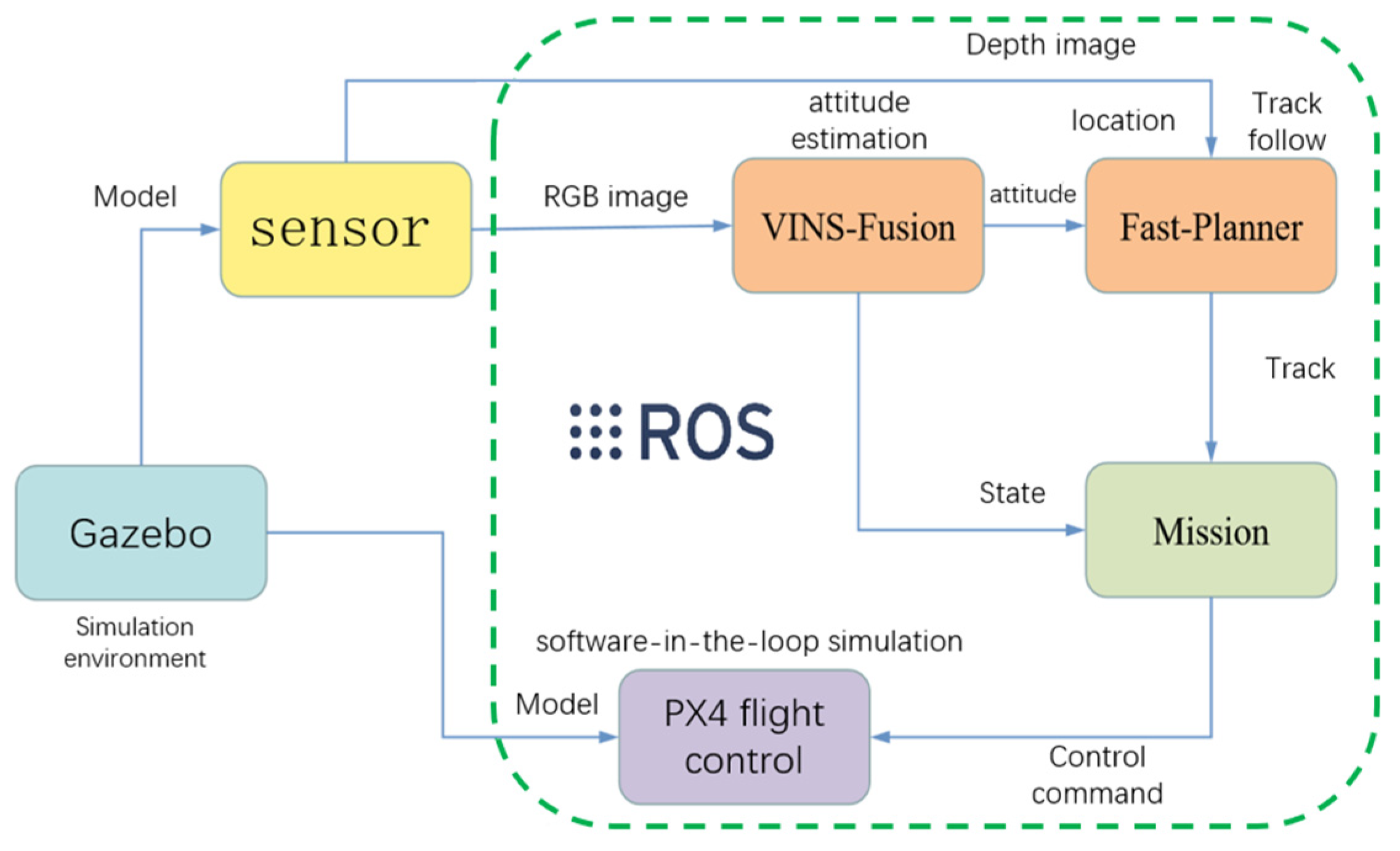
2.6. Path Planning Simulation of UAV in Photovoltaic Station Based on ROS Platform

On the basis of Section 2.5, this section uses the ROS platform (Kinetic Kame), combined with Gazebo (simulation tool in ROS environment) and Rviz (visualization tool in ROS environment), to simulate and show the autonomous flight state of the UAV in the unknown environment of the column obstacle, and further verify the path planning effect of the hybrid algorithm proposed in this paper.
Figure 6 is a 36 × 20 m, 1 m grid resolution column obstacle scene map, including randomly distributed gray columns with an average height of 5 m and local perception columns displayed by octomap, and a blue four-rotor UAV with a maximum flight line speed of 2 m/s, an angular velocity of 1.0 rad/s and a height of 1.5 m.
Before the experiment, the UAV parameters need to be configured, and the SLAM (simultaneous localization and mapping) algorithm is used to locate and map. Figure 7 shows the simulation system structure and data flow:

3. Results and Discussion

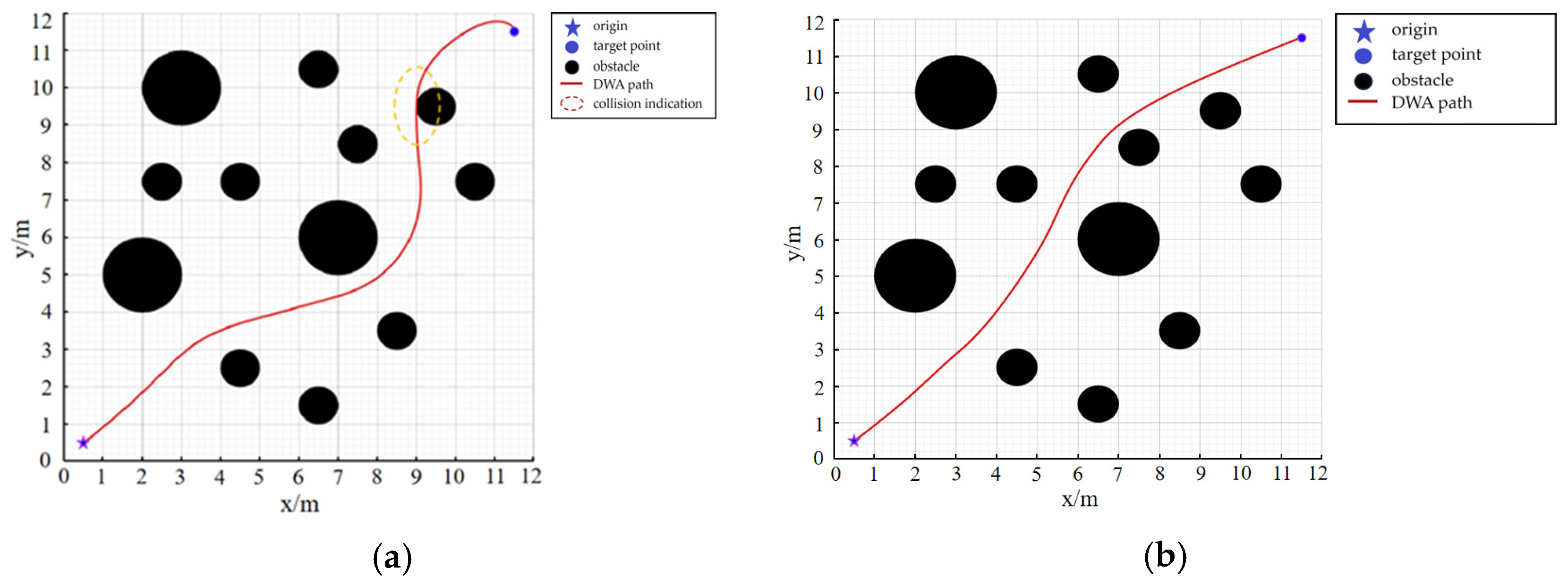
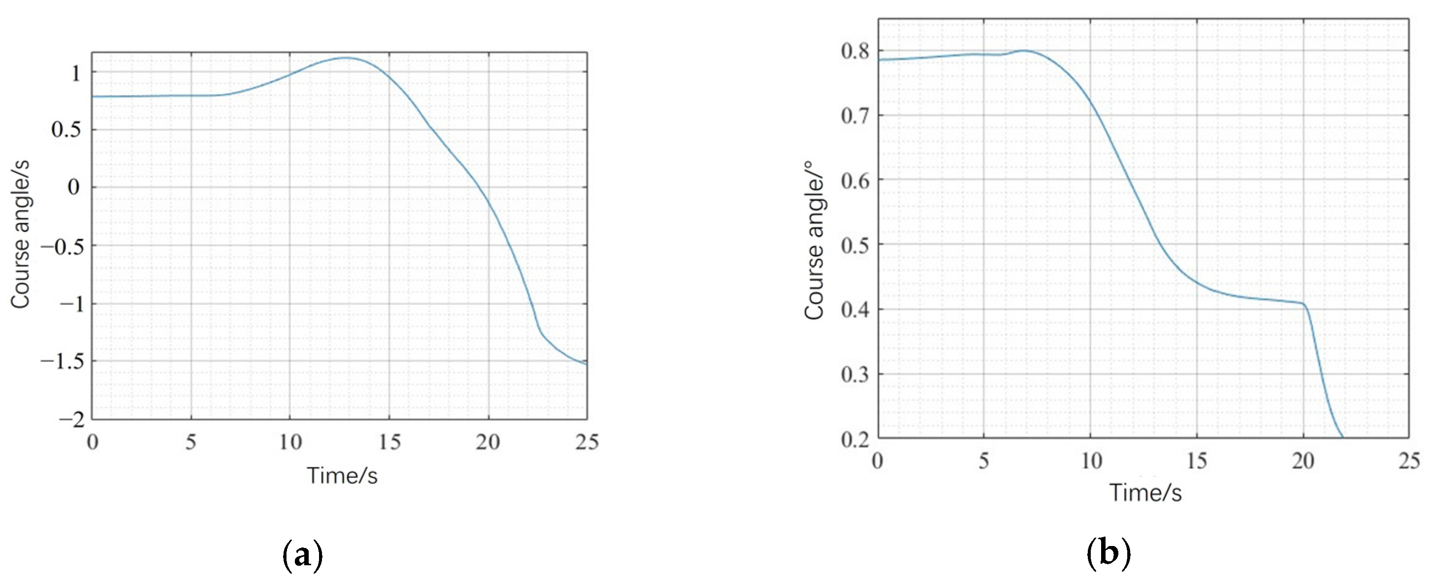
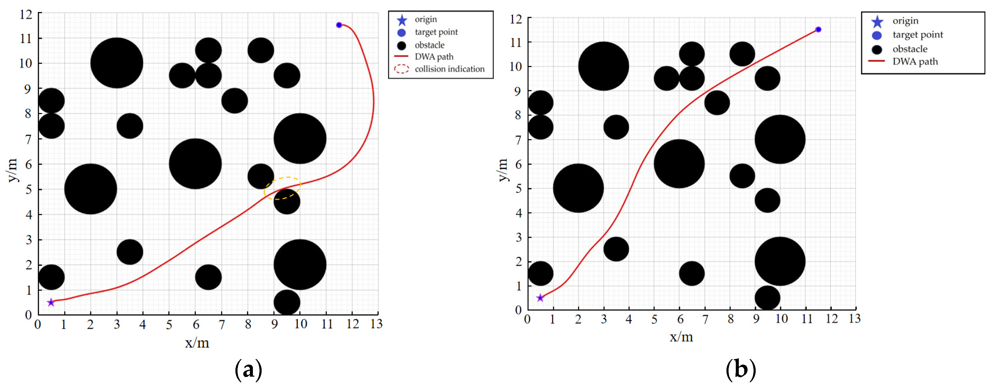
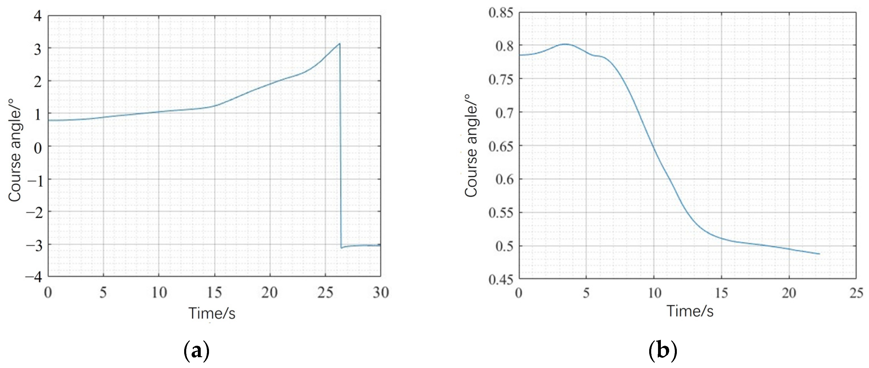
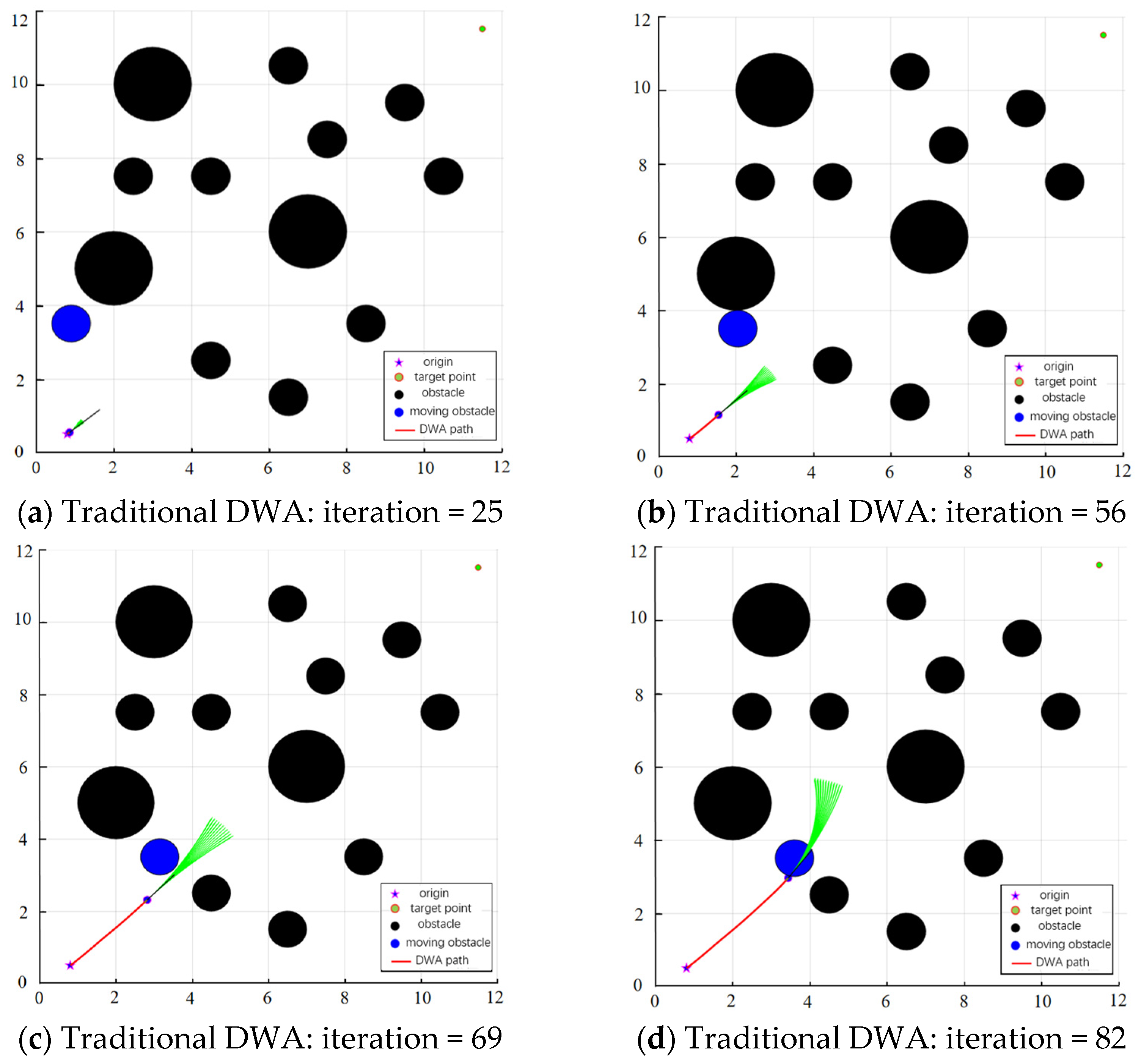
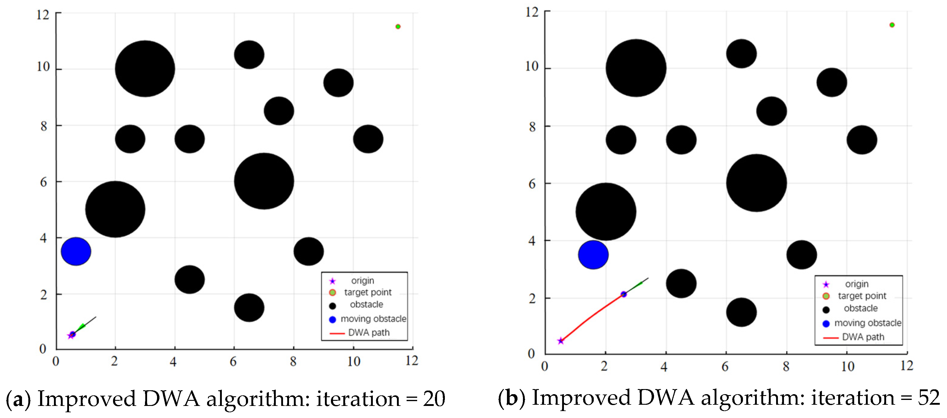
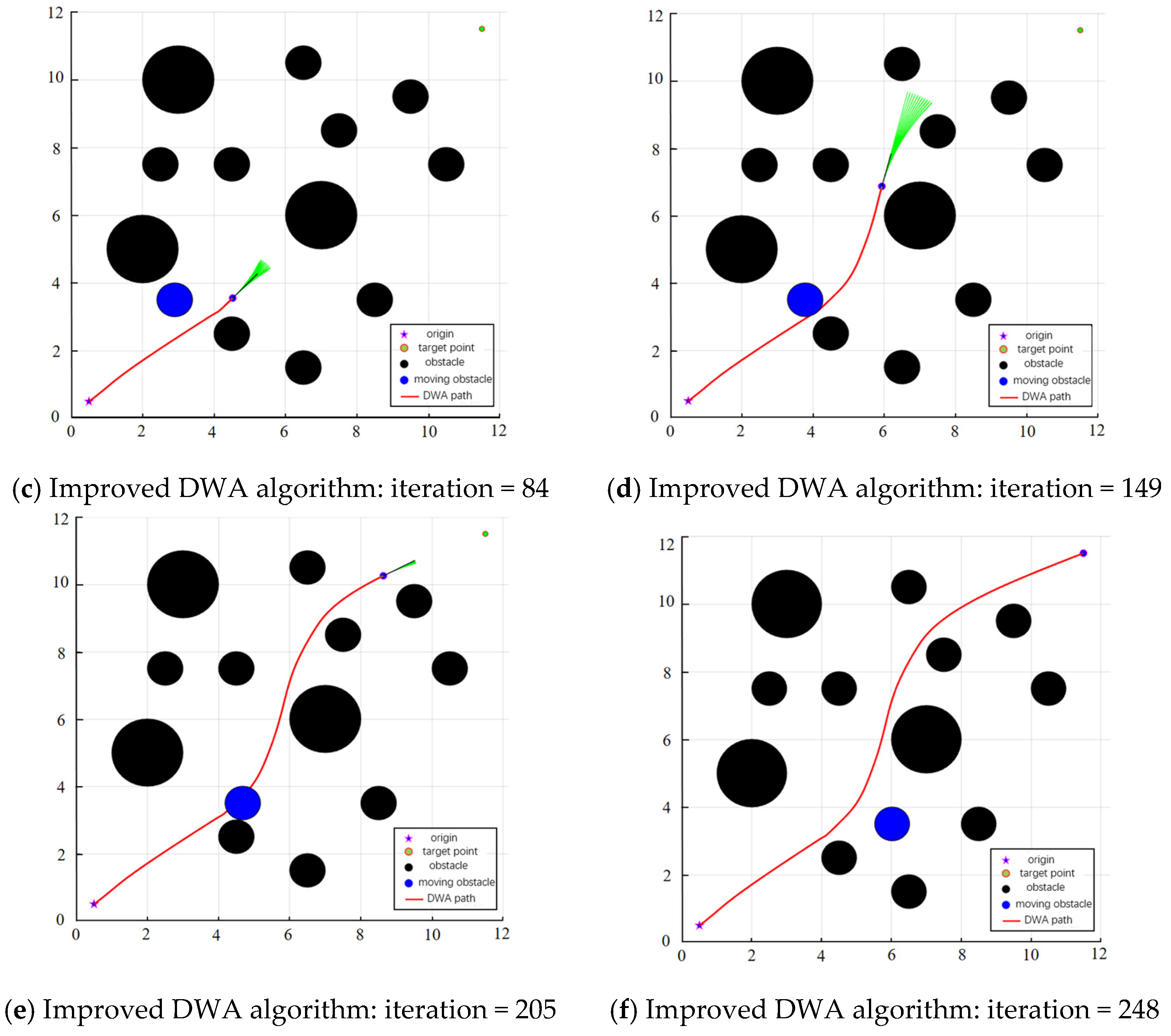
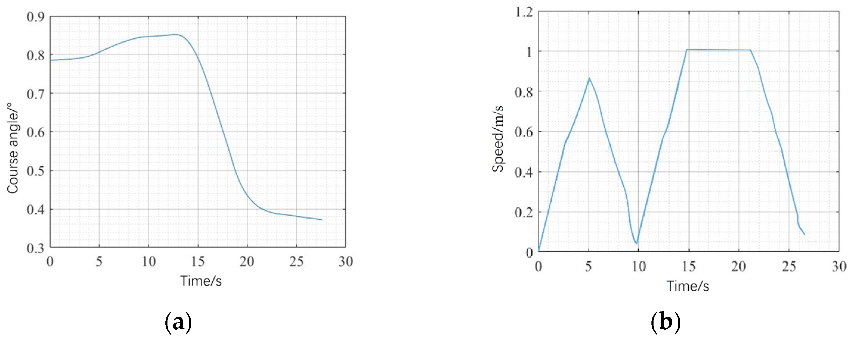
3.1. Simulation Experiment of Improved Dynamic Window Method

Figure 8 shows the simulation results in a simple environment. The black circle is a random obstacle, the pentagram is the starting point, the circle is the end point, and the red line is the algorithm path. The traditional DWA algorithm bypasses large obstacles and is prone to collision. The path is long and not smooth. It needs to turn sharply before the endpoint, and the heading angle fluctuates greatly, as shown in Figure 9a. The improved DWA algorithm has a more continuous and smooth path, a stable heading angle, and can safely cross dense obstacles to quickly reach the target, as shown in Figure 8b and Figure 9b.
It can be seen from the results in Table 1 that the improved DWA algorithm is superior to the traditional DWA algorithm in terms of path length, running time, minimum safe distance, and number of iterations. The path length is reduced by 21.01%, the running time is reduced by 34.08%, and the number of iterations is reduced by 25.42%. In addition, the minimum safety distance between the path planned by the traditional DWA algorithm and the obstacle is 0.054 m, which is easy to collide with the obstacle and poses a great potential safety hazard. The improved DWA algorithm can achieve more efficient access to the better path while ensuring a safe distance from the obstacle, so the planning effect is better.
Figure 10 and Figure 11 show the simulation results in the complex environment of scene 2. The analysis shows that the comparison effect of path planning in this scene is consistent with that in scene 1. The traditional DWA algorithm has obvious collision risk, and the generated path has large turning, long path length, and poor smoothness. The improved DWA algorithm can smoothly cross the dense area of obstacles and find a path with shorter length, smaller turning, and a smoother trajectory. Although the distance between the dense area of obstacles and the nearest obstacle is small, it still meets the safety conditions after expansion. The detailed experimental results and data are shown in Table 2.
From the data in Table 2, it can be seen that the path trajectory planned by the improved DWA algorithm in a complex environment can still ensure better results. While meeting the security conditions, the path length is reduced by 23.92% compared with the traditional DWA algorithm, the running time is reduced by 33.23%, and the number of iterations is reduced by 22.57%.
In order to verify the performance of the improved DWA algorithm in dealing with dynamic obstacles, a moving obstacle with an initial position of (0.5, 3.5) is added to the scene one map. When the robot moves, the obstacle moves in a straight line at a constant speed of 0.5 m/s. As the moving obstacle gradually approaches the robot, its running speed will slowly decrease. Figure 12 is the experimental result of the traditional DWA algorithm (α = 0.05, β = 0.3, γ = 0.3): In Figure 12a, in the 25th iteration, the robot moves towards the target, and the obstacle moves at a constant speed; in the 56th iteration of Figure 12b, the distance between the two is reduced, and the obstacle slows down; as the number of iterations increases, the obstacle approaches and the speed drops to 0.2 m/s. However, the weight of the algorithm is fixed, and the robot cannot avoid it in time. Finally, it collides with the obstacle in the 82nd iteration, as shown in Figure 12c,d.
The local path planning results of the improved DWA algorithm under the same map are shown in Figure 13. Figure 13a shows that when the robot is far away from the target and there are few obstacles, it accelerates forward; in Figure 13b–d, the robot approaches the obstacle, the speed decreases, and accelerates to avoid when encountering unknown obstacles, see Figure 14; after avoiding, the robot enters the static dense obstacle area, the speed decreases again, the azimuth angle is adjusted adaptively, and finally reaches the target quickly and stably, as shown in Figure 13e,f.
In summary, compared with the simulation results of traditional DWA and improved DWA algorithms in static and dynamic environments, the improved DWA algorithm improves the path quality and realizes real-time obstacle avoidance by adaptive weight, optimization evaluation function and dynamic obstacle response strategy, which is more in line with the flexible, continuous and smooth flight requirements of UAVs.

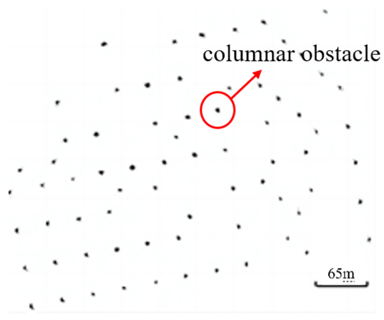
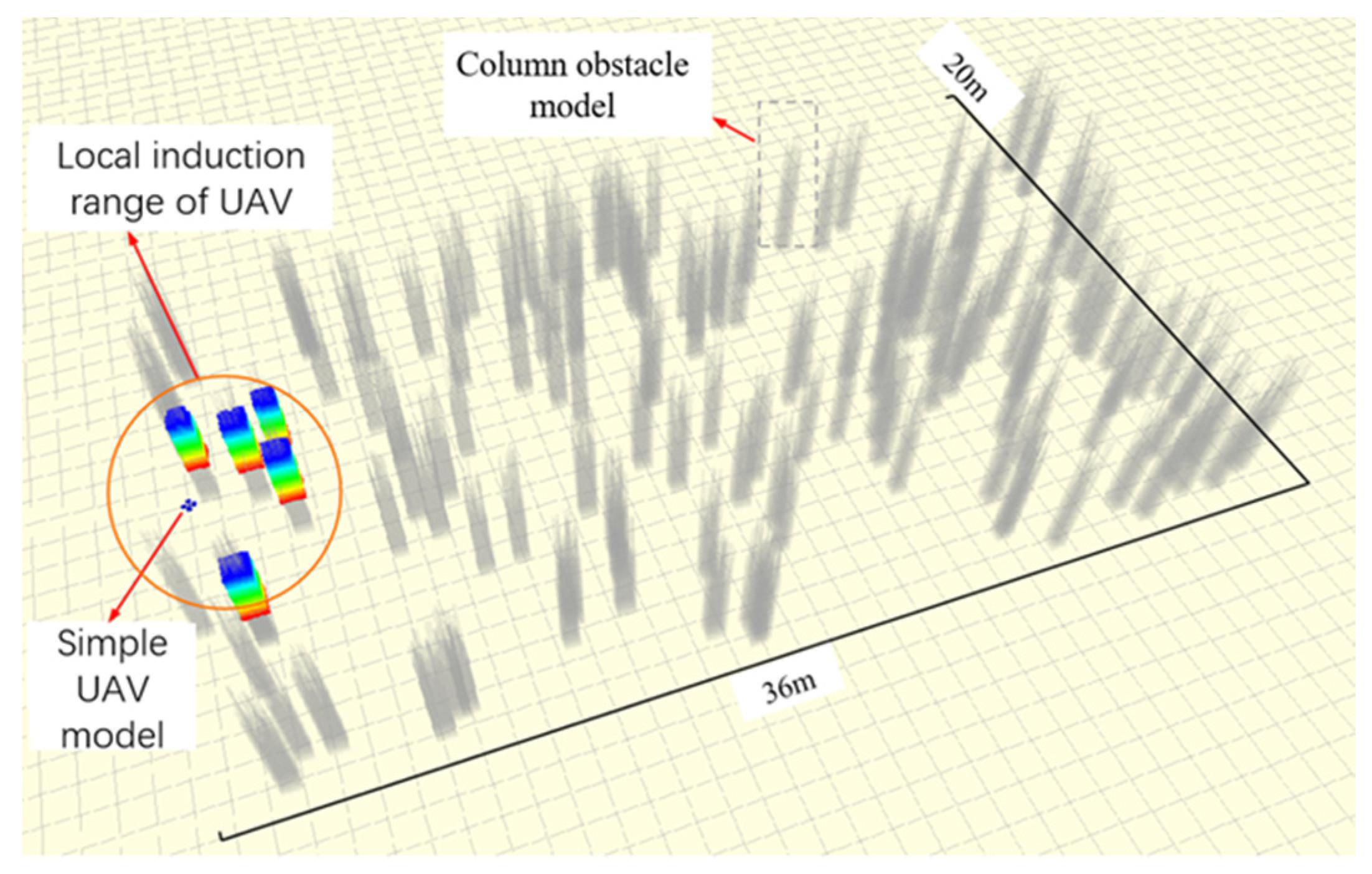
3.2. Simulation Verification of Hybrid Path Planning Method Based on Column Obstacle Map

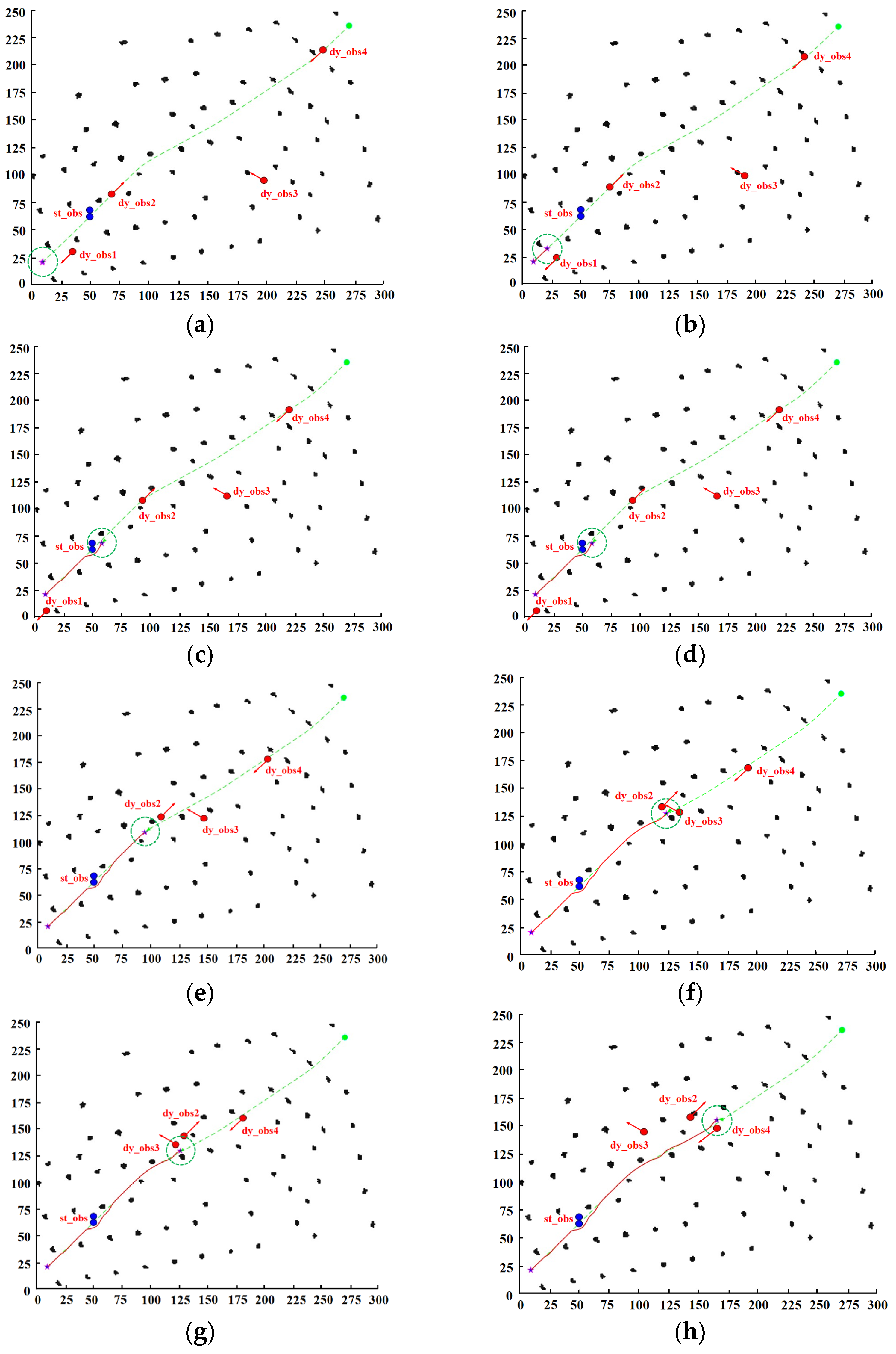
Simulation Experiment of Hybrid Path Planning in Transmission Tower-Detection Station-Photovoltaic Scenario

The experimental map is shown in Figure 15. After grid processing, black is the column obstacle, including the transmission tower and the detection station, and the blank is the passage area. In order to simulate unknown obstacles, fixed static obstacles (blue circle) and dynamic obstacles (red circle, 1 m/s uniform motion, red arrow indicating direction) are added. The obstacle avoidance range of the rolling window is twice the obstacle radius. The specific process is shown in Figure 15:
The UAV’s azimuth and velocity versus time curves during hybrid path planning are shown in Figure 16 below:
Table 3 shows that when an unknown obstacle is detected, the motion state is analyzed, the collision is predicted, and the obstacle avoidance strategy is called to realize real-time obstacle avoidance. Figure 16 and Table 3 verify the effectiveness of the hybrid path planning method in unknown static and dynamic obstacle environments in the transmission tower-detection station–photovoltaic scenario.
When multiple dynamic obstacles coexist, the hybrid path-planning algorithm presented in this study adopts a systematic methodology to prioritize obstacle avoidance. Initially, the algorithm assesses the collision risk associated with each dynamic obstacle by analyzing its motion trajectory in relation to the UAV’s planned path. Drawing on equations analogous to those used in single-obstacle scenarios, it computes the time to potential collision points for all obstacles. This calculation incorporates factors such as the relative distances, velocities, and dimensions of the UAV and the obstacles. The obstacle with the highest immediate collision risk is assigned the highest priority for evasion. Specifically, if an obstacle’s trajectory is set to intersect with the UAV’s path within the shortest time frame, and the time-to-collision (∆t) is shorter than the predefined time limit (∆t0) in the dynamic obstacle prediction and avoidance strategy, it becomes the primary obstacle to be addressed. This section has been added under Table 3 in the original text.

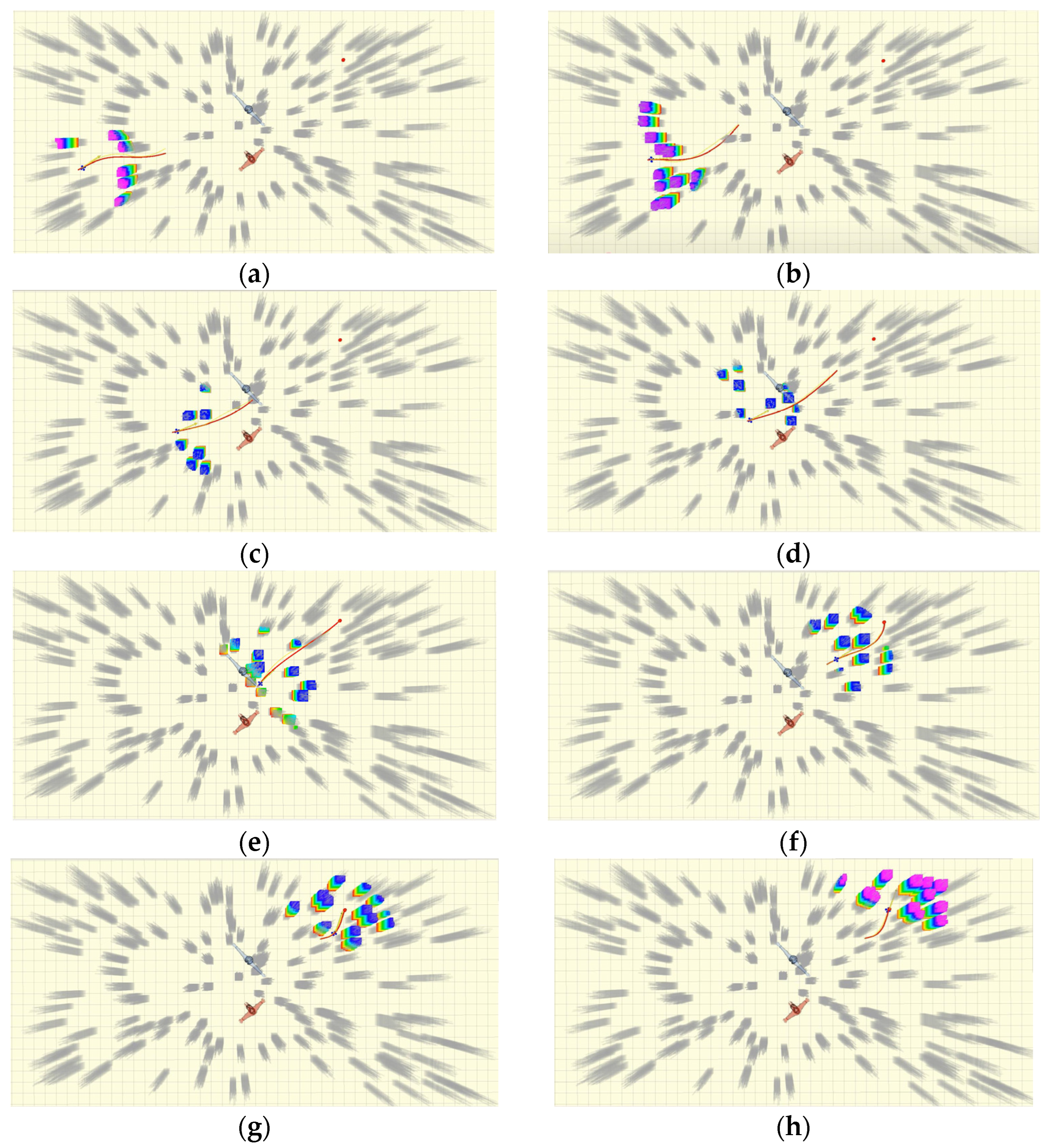
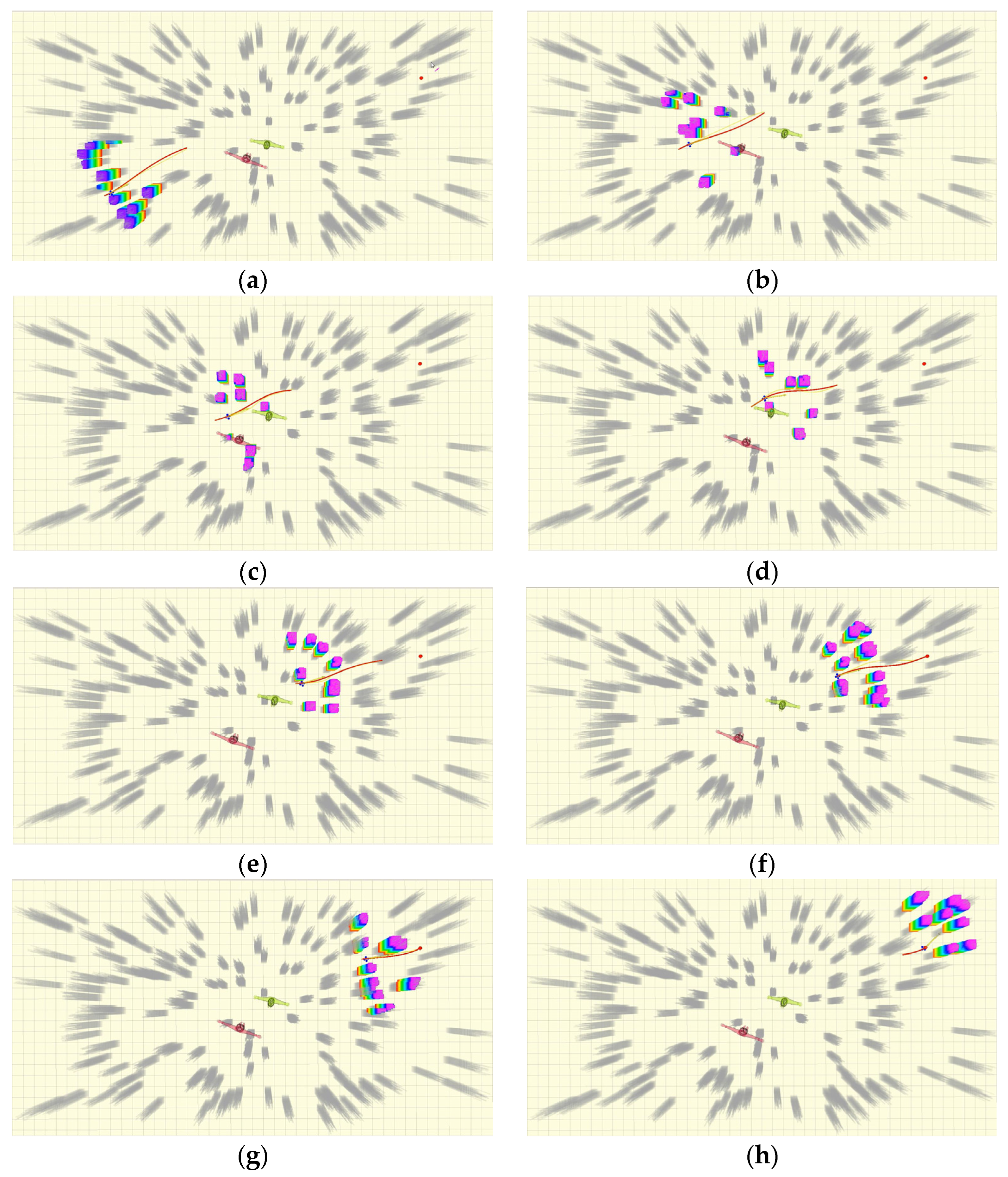
3.3. Simulation of UAV Path Planning in Pillar Obstacle Scene Based on ROS Platform

The simulation experiments in this section include static environment path planning, unknown static obstacle path planning, and unknown dynamic obstacle path planning. The static environment is the random column obstacle scene map in Figure 6. The static pedestrian model is an unknown static obstacle, and pedestrian movement constitutes a dynamic obstacle. In the experiment, Rviz is used to set the end point and observe the path of the hybrid path planning algorithm. Figure 17 is the static environment result.
In Figure 17, the color column is a real-time perception of the column obstacle, and the gray is an external barrier; the red trajectory is the pre-generated path of the hybrid path planning algorithm, and the orange arrow is the UAV heading. The UAV adjusts the path in real time to ensure the safe arrival of the target. Figure 18 is the scene diagram of adding two fixed pedestrian models as unknown static obstacles.
After setting the target point position, the UAV calls the hybrid path planning algorithm to pre-plan the flight path, and senses the surrounding environment information in real time through the airborne sensor to provide support for local dynamic obstacle avoidance. The specific simulation results of this part are shown in Figure 19.
It can be seen from Figure 19 that the path generated by the current pre-planning is dynamically adjusted by detecting the change of obstacles in real time during the flight of the UAV, and a safe and continuous smooth path is selected to cross the area where the unknown obstacles are located, and finally reach the target point smoothly.
In order to verify the obstacle avoidance path planning ability of the UAV in the dynamic obstacle environment, the motion constraints are applied to the pedestrian model inFigure 18, so that it performs random reciprocating motion within a certain range of the initial position, and the initial moving speed vx = 0.6 m/s, vy = 0.8 m/s, acceleration ax = 0.1 m/s2, ay = 0 m/s2. The path planning process of UAV in a dynamic environment is shown inFigure 20.
Figure 20 shows that the UAV flies according to the optimal path planned by the hybrid algorithm when the dynamic obstacle does not appear in the sensing range. As the distance decreases, the rolling window detects dynamic obstacles. By predicting its movement, judging the collision risk, calling the obstacle avoidance strategy, real-time obstacle avoidance, and safe arrival of the target are achieved. The results are consistent with the verification of Matlab r2022a, which once again proves the effectiveness of the hybrid algorithm in the dynamic environment under column obstacle scenes.

4. Conclusions

This paper focuses on enhancing the path planning ability of unmanned aerial vehicles (UAVs) in complex photovoltaic power station environments with columnar obstacles such as transmission towers and detection stations. Aiming at the deficiencies of the traditional DWA (dynamic window qpproach) algorithm in dynamic obstacle avoidance, an improved DWA algorithm is proposed. This algorithm not only takes into account the physical size of the UAV and expands the obstacles to optimize path planning and avoid collisions, but also introduces dynamic adjustment factors. These factors include azimuth-adaptive dynamic adjustment based on the distance to the target point and speed dynamic adjustment based on the complexity of the obstacles, which significantly improves the adaptability and real-time performance of the algorithm in different environments. In addition, by adding an evaluation function and its weight for the distance between the simulated trajectory and the global target, the guidance of the target search is further enhanced, enabling the UAV to find the optimal path more quickly and accurately.
Based on the improved DWA algorithm, this paper further proposes a hybrid path planning algorithm suitable for the photovoltaic power station environment. This algorithm combines the advantages of the improved A* algorithm. On the basis of global path planning, it can automatically call the dynamic obstacle avoidance strategy according to real-time environmental information, achieving flexible adjustment of the local path. When an obstacle is detected and a collision risk is predicted, the algorithm can quickly call the avoidance strategy to avoid the obstacle. If necessary, it can call the improved DWA algorithm for local path replanning to ensure that the UAV can safely and efficiently return to the global optimal path and smoothly reach the target position. The simulation results show that the hybrid algorithm has a significant improvement in path length, safety, smoothness, and real-time obstacle avoidance ability.
Despite the significant performance improvements, the methods in this paper still have certain limitations. In terms of algorithm computational resource consumption, especially when dealing with large-scale and complex scenarios, the improved A* algorithm and DWA algorithm still require a large amount of computational resources. The computational load may increase significantly when there are numerous obstacles and frequent updates of environmental information, affecting the real-time response speed of the UAV. In addition, sensor errors are also a factor that needs attention. In the simulation environment, we did not fully consider the impact of sensor errors on path planning. In practical applications, sensor errors may lead to inaccurate perception of obstacle positions and dynamic information, thereby affecting the accuracy of the planned path. Future research will continue to optimize computational efficiency and further improve the robustness of the algorithm against sensor errors to cope with more complex and dynamic environments.

Author Contributions

Conceptualization, Y.G. and S.L.; methodology, Y.G. and S.L.; software, Y.G. and S.L.; validation, Y.G. and S.L.; formal analysis, Y.G. and S.L.; investigation, Y.G. and S.L.; resources, Y.G. and S.L.; data curation, Y.G. and S.L.; writing—original draft preparation, Y.G. and S.L.; writing—review and editing, Y.G. and S.L.; visualization, Y.G. and S.L.; supervision, Y.G. and S.L.; project administration, Y.G. and S.L.; funding acquisition, Y.G. and S.L. All authors have read and agreed to the published version of the manuscript.

Funding

This research received no external funding.

Data Availability Statement

The raw data required to reproduce these findings cannot be shared at this time as the data also forms part of an ongoing study.

Conflicts of Interest

The authors declare no conflicts of interest.

References

  1. Feng, L.; Chen, C.; Xin, W. Review of Intelligent Path Planning for UAV Inspection of Solar Power Stations. Metrol. Meas. Tech. 2024, 50, 9396+100. [Google Scholar]
  2. Tang, Z. Design of a Scheduling System for Cleaning Robots for Photovoltaic Modules Based on UAV. Ph.D. Thesis, China Jiliang University, Hangzhou, China, 2021. [Google Scholar]
  3. Li, C.; Han, X. Application and development trend of multi-rotor UAV in agricultural plant protection. Shangdong Agric. Mech. 2024, 50–51. [Google Scholar] [CrossRef]
  4. Lan, Y.; Wang, L.; Zhang, Y. Application and prospect on obstacle avoidance technology for agricultural UAV. Trans. Chin. Soc. Agric. Eng. 2018, 34, 104–113. [Google Scholar]
  5. Huang, S. Research on Global Path Planning and Local Obstacle Avoidance of Multi-UAV. Master’s Thesis, Jilin University, Changchun, China, 2024. [Google Scholar]
  6. Liu, Q.; Shu, L.; Liu, G.; Li, A. A survey of low altitude UAV path planning algorithms. Adv. Aeronaut. Sci. Eng. 2023, 14, 24–34. [Google Scholar]
  7. Xiong, J.; Duan, X. Path planning for UAV based on improved dynamic step RRT algorithm. J. Phys. Conf. Ser. 2021, 1983, 012034. [Google Scholar] [CrossRef]
  8. Tang, F.; Li, K.; Xu, F.; Han, L.; Zhang, H.; Yang, Z. Optimal ant colony algorithm for UAV airborne LiDAR route planning in densely vegetated areas. J. Appl. Remote Sens. 2023, 17, 046506. [Google Scholar] [CrossRef]
  9. Li, Y.; Dong, X.; Ding, Q.; Xiong, Y.; Liao, H.; Wang, T. Improved A-STAR Algorithm for Power Line Inspection UAV Path Planning. Energies 2024, 17, 5364. [Google Scholar] [CrossRef]
  10. Liu, L.; Lin, J.; Yao, J.; He, D.; Zheng, J.; Huang, J.; Shi, P. Path Planning for Smart Car Based on Dijkstra Algorithm and Dynamic Window Approach. Wirel. Commun. Mob. Comput. 2021, 2021, 8881684. [Google Scholar] [CrossRef]
  11. Ju, C.; Luo, Q.; Yan, X. Path planning using an improved A* algorithm. In Proceedings of the 2020 11th International Conference on Prognostics and System Health Management, Jinan, China, 23–25 October 2020. [Google Scholar]
  12. Gao, J.; Zhang, Z. Obstacle Avoidance Path Planning of UAV in 3D Space Based on Improved A* Algorithm. Comput. Meas. Control 2023, 31, 203–209+223. [Google Scholar]
  13. Zhou, J.; Yang, L.; Zhang, C. Indoor robot path planning based on improved A* algorithm. Mod. Electron. Tech. 2022, 45, 181–186. [Google Scholar]
  14. He, Y.; Cao, L.; Xu, L. Mobile robot path planning based on improved A* algorithm. China South. Agric. Mach. 2024, 55, 31–34. [Google Scholar]
  15. Shi, Y.; Chen, H.; Zhang, L.; Sun, P.; Pei, P.; Li, D. Research on path planning of AGV transport robot based on improved A* algorithm. Manuf. Technol. Mach. Tool 2022, 19–22. [Google Scholar] [CrossRef]
  16. Yan, S.; Shi, X.; Zhang, Z. Three-dimensional Path Planning of Urban Logistics UAVs. Sci. Technol. Eng. 2024, 24, 12781–12788. [Google Scholar]
  17. Tang, Y.; Zheng, E.; Qiu, X. 3D UAV Trajectory Planning Based on Optimized Bidirectional A and Artificial Potential Field Method. J. Air Force Eng. Univ. 2024, 25, 69–75. [Google Scholar]
  18. Hu, M.; Li, X.; Ren, Z.; Zeng, S. UAV 3D Path Planning Based on A* Algorithm with Improved Heuristic Function. Acta Armamentarii 2024, 45, 302–307. [Google Scholar]
  19. Li, J.; Kang, F.; Chen, C.; Tong, S.; Jia, Y.; Zhang, C.; Wang, Y. The Improved A* Algorithm for Quadrotor UAVs under Forest Obstacle Avoidance Path Planning. Appl. Sci. 2023, 13, 4290. [Google Scholar] [CrossRef]
  20. Lin, J.; Xi, W.; Zhou, J. Path planning of mobile robots based on improved PRM and APF. Foreign Electron. Meas. Technol. 2022, 41, 1–6. [Google Scholar]
  21. Jia, Q.; Zhao, X.; Meng, Z. Path Planning Algorithm in Dynamic Environment Based on Improved Dynamic Window Approach. Sci. Technol. Eng. 2024, 24, 6313–6319. [Google Scholar]
  22. Luan, T.; Wang, H.; You, B.; Sun, M. TEB unmanned vehicle navigation method for position and attitude auxiliary points in narrow space. Chin. J. Sci. Instrum. 2023, 44, 121–128. [Google Scholar]
  23. Yan, L.; Fan, X. AGV local path planning based on adaptive dynamic window approach. J. Nanjing Univ. Inf. Sci. Technol. 2024. [Google Scholar] [CrossRef]
  24. Jiang, H.; Wu, T.; Ren, J.; Li, M.; Xiong, A.; Jia, J. Research on Local Path Planning of Mobile Robot Based on Improved Dwa Algorithm. Mach. Des. Res. 2024, 40, 229–234. [Google Scholar]
  25. Han, Z.; Li, L.; He, Z.; Zong, L.; Dai, Y. USV collision avoidance method combining DWA and DDPG algorithm. Electron. Meas. Technol. 2024, 47, 80–87. [Google Scholar]
  26. Xiong, D.; Ning, Y.; Wang, J.; Zeng, L. Local Path Planning of Mobile Robot Based on Improved DWA. Ind. Control Comput. 2024, 37, 102–104. [Google Scholar]
  27. Li, X.; Fang, J. Research on UAV Path Planning by A* Algorithm and DWA Method in the Urban Environment. Unmanned Syst. Technol. 2023, 6, 61–70. [Google Scholar]
  28. Li, J.; Xiong, X.; Yang, K.; Yan, Y.; Liang, T.; Liu, J. Research on indoor UAV path planning based on fusion algorithm. Foreign Electron. Meas. Technol. 2024, 43, 173–181. [Google Scholar]
  29. Jiang, H.; Zhang, Z. Research on Fusion Optimization Strategy Based on A* and Dynamic Window Approach Algorithms. Mach. Electron. 2024, 42, 15–21. [Google Scholar]
  30. Ma, Z.; Zhu, X.; Ma, L. Research on robot path planning based on improved A* and DWA. Mod. Electron. Tech. 2024, 47, 177–186. [Google Scholar]
  31. Zhao, H.; Fu, H.; Yang, F.; Qu, C.; Zhou, Y. Data-driven offline reinforcement learning approach for quadrotor’s motion and path planning. Chin. J. Aeronaut. 2024, 37, 386–397. [Google Scholar] [CrossRef]
  32. Wang, Y.; Wang, H.; Liu, Y.; Wu, J.; Lun, Y. 6-DOF UAV Path planning and tracking control for obstacle avoidance: A deep learning-based integrated approach. Aerosp. Sci. Technol. 2024, 151, 109320. [Google Scholar] [CrossRef]
  33. Varma, K.S.; Kumari, S.L. Robotic vision based obstacle avoidance for navigation of unmanned aerial vehicle using fuzzy rule based optimal deep learning model. Evol. Intell. 2023, 17, 2193–2212. [Google Scholar] [CrossRef]
  34. Ni, F.; Jin, B.; Gao, X.; Li, Q. Cooperative Obstacle Avoidance Planning via A*-BDWA Fusion for Unmanned Aerial Vehicles. IAENG Int. J. Comput. Sci. 2024, 51, 1793–1803. [Google Scholar]
  35. Zhao, Z.; Wan, Y.; Chen, Y. Deep Reinforcement Learning-Driven Collaborative Rounding-Up for Multiple Unmanned Aerial Vehicles in Obstacle Environments. Drones 2024, 8, 464. [Google Scholar] [CrossRef]
  36. Wang, X.; Cheng, M.; Zhang, S.; Gong, H. Multi-UAV Cooperative Obstacle Avoidance of 3D Vector Field Histogram Plus and Dynamic Window Approach. Drones 2023, 7, 504. [Google Scholar] [CrossRef]
  37. Shen, K.; You, Z.; Liu, Y.; Huang, T. Mobile robot planning based on improved A* algorithm. Appl. Res. Comput. 2023, 40, 75–79. [Google Scholar]
  38. Tarokh, M. Hybrid intelligent path planning for articulated rovers in rough Terrain. Fuzzy Sets Syst. 2008, 159, 2927–2937. [Google Scholar] [CrossRef]
Figure 1. Schematic diagram of expansion treatment.
Electronics 14 01963 g001
Figure 2. Schematic diagram of the relative motion trajectory between the robot and the obstacle.
Electronics 14 01963 g002
Figure 3. Framework structure diagram of the hybrid path planning method.
Electronics 14 01963 g003
Figure 4. Field transmission tower-detection station-photovoltaic scene. (a) Photovoltaic panels and telegraph poles; (b) photovoltaic arrays and transmission towers; (c) meteorological monitoring equipment for photovoltaic stations.
Electronics 14 01963 g004
Figure 5. Two-dimensional obstacle map of the station–photovoltaic scene.
Electronics 14 01963 g005
Figure 6. Map of the UAV experimental scenes.
Electronics 14 01963 g006
Figure 7. The overall structure of the simulation system.
Electronics 14 01963 g007
Figure 8. Algorithm simulation results in the simple environment of scenario 1. (a) Traditional DWA algorithm path planning trajectory. (b) Improved DWA algorithm path planning trajectory.
Electronics 14 01963 g008
Figure 9. Heading angle variation before and after algorithm improvement of scenario 1. (a) Conventional DWA algorithm heading angle variation graph. (b) Improved DWA algorithm heading angle var-iation graph.
Electronics 14 01963 g009
Figure 10. Algorithm simulation results in the complex environment of scenario 2. (a) Traditional DWA algorithm path plan-ning trajectory. (b) Improved DWA algorithm path plan-ning trajectory.
Electronics 14 01963 g010
Figure 11. Heading angle variation before and after algorithm improvement of scenario 2. (a) Conventional DWA algorithm heading angle variation graph. (b) Improved DWA algorithm heading angle variation graph.
Electronics 14 01963 g011
Figure 12. Simulation results of the conventional DWA algorithm in scenario 1. Note: The green area represents the possible path selection for real-time calculation and prediction by the algorithm.
Electronics 14 01963 g012
Figure 13. Simulation results of the improved DWA algorithm in scenario 1. Note: The green area represents the possible path selection for real-time calculation and prediction by the algorithm.
Electronics 14 01963 g013aElectronics 14 01963 g013b
Figure 14. Heading angle and speed variation chart for improved DWA algorithm. (a) Improved DWA algorithm heading angle variation graph. (b) Improved DWA algorithm speed varia-tion graph.
Electronics 14 01963 g014
Figure 15. Column obstacle scene dynamic environment path planning process. Note: Figures (aj) show the hybrid algorithm path planning states at different moments. The pentagram is the starting point, the green circle is the target position, the blue circle is the unknown static obstacle, the red circle is the unknown dynamic obstacle, the dashed circle is the real-time position of the UAV, the dashed line is the optimal path when there are no unknown obstacles, and the solid line is the actual path when obstacles are added.
Electronics 14 01963 g015aElectronics 14 01963 g015b
Figure 16. Azimuth and velocity change curve.
Electronics 14 01963 g016
Figure 17. UAV path planning in static environments. Note: The color column is a real-time perception of the column obstacle, the gray is an obstacle outside the perception range; the blue flyer is a four-rotor UAV, the red trajectory is the pre-generated path, and the orange arrow is the UAV heading.
Electronics 14 01963 g017
Figure 18. Unknown static obstacle scene.
Electronics 14 01963 g018
Figure 19. Path planning process of UAV in an unknown static obstacles environment. Note: Figures (a~h) show the UAV path planning state at different moments.
Electronics 14 01963 g019
Figure 20. Path planning process of UAV in an unknown dynamic obstacle environment. Note: Figures (ah) show the UAV path planning state at different moments, and the motion constraints are applied to the pedestrian model.
Electronics 14 01963 g020
Table 1. Comparison of data before and after algorithm improvement in scenario 1.
MethodologyPath Length/mRunning Time/sMinimum Safe Distance/mNumber of Iterations
Traditional DWA20.3233.540.054295
Improved DWA16.0522.110.273220
Table 2. Comparison of data before and after algorithm improvement in scenario 2.
MethodologyPath Length/mRunning Time/sMinimum Safe Distance/mNumber of Iterations
Traditional DWA21.0331.510.030288
Improved DWA16.0021.040.196223
Table 3. Column obstacle dynamic environment path planning analysis table.
Obstacles and TypesCrash PredictionWhether or Not a Collision OccursAdoption of Avoidance Strategies
st_obsLie on the globally optimal path.YesDecelerate and invoke the improved DWA algorithm for local planning.
dy_obs1The movement trajectory does not intersect with the drone trajectory and travels in opposite directions.NoNull.
dy_obs2The trajectory partially overlaps with the drone trajectory and moves in the same direction.YesDecelerate, stop, and wait.
dy_obs3The movement trajectory intersects with the drone trajectory and moves in a different direction.YesDecelerate, stop, and wait.
dy_obs4The movement trajectory partially coincides with the drone trajectory and moves in the opposite direction.YesDecelerate and invoke the improved DWA algorithm for local path replanning.
Disclaimer/Publisher’s Note: The statements, opinions and data contained in all publications are solely those of the individual author(s) and contributor(s) and not of MDPI and/or the editor(s). MDPI and/or the editor(s) disclaim responsibility for any injury to people or property resulting from any ideas, methods, instructions or products referred to in the content.

