Article

FI-NPI: Exploring Optimal Control in Parallel Platform Systems

1
School of Automation, University of Electronic Science and Technology of China, Chengdu 610054, China
2
College of Resource and Environment Engineering, Guizhou University, Guiyang 550025, China
3
Department of Geography and Anthropology, Louisiana State University, Baton Rouge, LA 70803, USA
*
Authors to whom correspondence should be addressed.
Electronics 2024, 13(7), 1168; https://doi.org/10.3390/electronics13071168
Submission received: 30 January 2024 / Revised: 19 March 2024 / Accepted: 20 March 2024 / Published: 22 March 2024
(This article belongs to the Special Issue State-of-the-Art Research in Systems and Control Engineering)

Abstract

:
Typically, the current and speed loop closure of servo motor of the parallel platform is accomplished with incremental PI regulation. The control method has strong robustness, but the parameter tuning process is cumbersome, and it is difficult to achieve the optimal control state. In order to further optimize the performance, this paper proposes a double-loop control structure based on fuzzy integral and neuron proportional integral (FI-NPI). The structure makes full use of the control advantages of the fuzzy controller and integrator to improve the performance of speed closed-loop control. And through the feedforward branch, the speed error is used as the teacher signal for neuron supervised learning, which improves the effect of current closed-loop control. Through comparative simulation experiments, this paper verifies that the FI-NPI controller has a faster dynamic response speed than the traditional PI controller. Finally, in this paper, the FI-NPI controller is implemented in C language in the servo-driven lower computer, and the speed closed-loop test of the BLDC motor is carried out. The experimental results show that the FI-NPI double-loop controller is better than the traditional double-PI controller in performance indicators such as convergence rate and RMSE, which confirms that the FI-NPI double-loop controller is more suitable for BLDC servo control.

1. Introduction

There are two servo driving modes commonly used in a Six-Degrees of Freedom (6-DOF) parallel platform: a hydraulic rod [1,2] and a brushless DC motor with servo system [3,4,5]. Due to the high energy density of the hydraulic rod, the parallel platform driven by the hydraulic rod performs well in terms of dynamic performance, which is especially suitable for situations with high dynamic response requirements and heavy loads [6,7,8]. However, hydraulic platforms also have some disadvantages, such as their high cost, complex mechanical structure and hydraulic valve control structure, and the need for regular maintenance. Relatively speaking, the structure of the parallel platform based on a servo motor drive is relatively simple. Among servo motors, common types include stepper motors, brushless DC motors (BLDC), and voice coil motors, among others [9,10]. Among them, the BLDC has attracted much research attention due to its small size, light weight, and long life [11]. Some scholars have used the Autoregressive (ARX) model in MATLAB toolbox to perform the second-order system approximation and parameter identification of BLDC servo drive so as to obtain the mathematical model in the form of BLDC servo drive’s transfer function [12]. Some other scholars have carried out the state space modeling of BLDC servo drive in the MATLAB-SIMULINK environment, which provides a better method for the design of BLDC motor in high dynamic load performance and working range through simulation experiments [13].
In BLDC servo control, PI and its improved algorithms are usually used to achieve closed-loop control of torque, speed, and position [14,15]. Ali, T. et al. used PI control to complete the speed and position control of the aircraft cabin door, such that the accurate door model system integrated with BLDC improved the torque [16]. Alzuabidi, Ohaa et al. conducted an analytical modeling of the PWM speed control of a permanent magnet brushless DC motor (PMBLDC), which consists of a voltage source inverter, a Hall sensor, a PI controller, and a circulation circuit [17]. In particular, a second-order low-pass filter is added to the PI controller in order to reduce the harmonic content of the inverter current. Hans, S. et al. used a fixed-order H∞ controller and introduced the particle swarm optimization algorithm to determine the optimal position of the rotor [11]. It is experimentally verified that the controller greatly reduces the torque obtained by the motor and also improves the speed. Zhang, Z. et al. used Fuzzy PID controller instead of PI controller in the speed loop to control attitude of flywheel [18]. Intidam, A. used Optimized PI-ANFIS Controller in the speed loop, which uses a neuro-fuzzy inference system to change PI parameter to achieve better control [19].
The key to optimize the BLDC servo drive is to select the appropriate BLDC motor drive method. Common driving methods for BLDC include the six-step commutation method [20], sinusoidal pulse width modulation (SPWM) [21], and space vector pulse width modulation (SVPWM) [22]. SVPWM is a driving method that uses spatial voltage vector switching [23] to control the magnitude and direction of BLDC current. By using this driving method, the working current of the BLDC presents a sine wave shape, thereby reducing the torque ripple, and compared with other driving methods, it has a higher voltage utilization rate. Based on the SVPWM drive, field-oriented control (FOC) is used to decouple flux linkage, which simplifies the closed-loop control process of BLDC. This makes FOC the main way to drive servo control systems.
Nowadays, the artificial intelligence method and advanced control method is used in many traditional fields. Compared with traditional PI methods, the fuzzy control model is based on flexible fuzzy rules and can be used in nonlinear system. However, PD-like fuzzy control model is difficult to achieve high precision, and how to solve the steady-state error is the key to this control model [24]. In this paper, a double-loop control structure based on fuzzy integral and neuron proportional integral (FI-NPI) is proposed. This is a controller with better closed-loop control performance. Supervised learning of neurons is introduced to improve the control effect of the current loop, and fuzzy control and integral control are used to improve the control effect of the speed loop. Firstly, fuzzy control is used to calculate the reference current Iq_ref in current loop according to the error and difference of error in speed loop. And the integration method is added in the fuzzy control model to eliminate steady-state error of speed loop. Then, neuron PI controls BLDC Iq are used to trace the Iq_ref. The comparison simulation experiment between the FI-NPI controller and the traditional PI controller is completed on a 6-DOF parallel platform. Experimental results show that the dynamic response speed of the FI-NPI controller is faster. The FI-NPI controller is implemented in the lower computer of the servo drive by using C language, and the speed closed-loop test of the brushless DC motor under the state of no-load and on-load is completed. The test results demonstrate that the FI-NPI double loop controller outperforms the double PI controller in terms of performance indicators like convergence rate and RMSE. This further demonstrates the superior performance of the new servo controller. And we can conclude that the FI-NPI double loop controller is a more appropriate servo control method for BLDC.

2. Methods

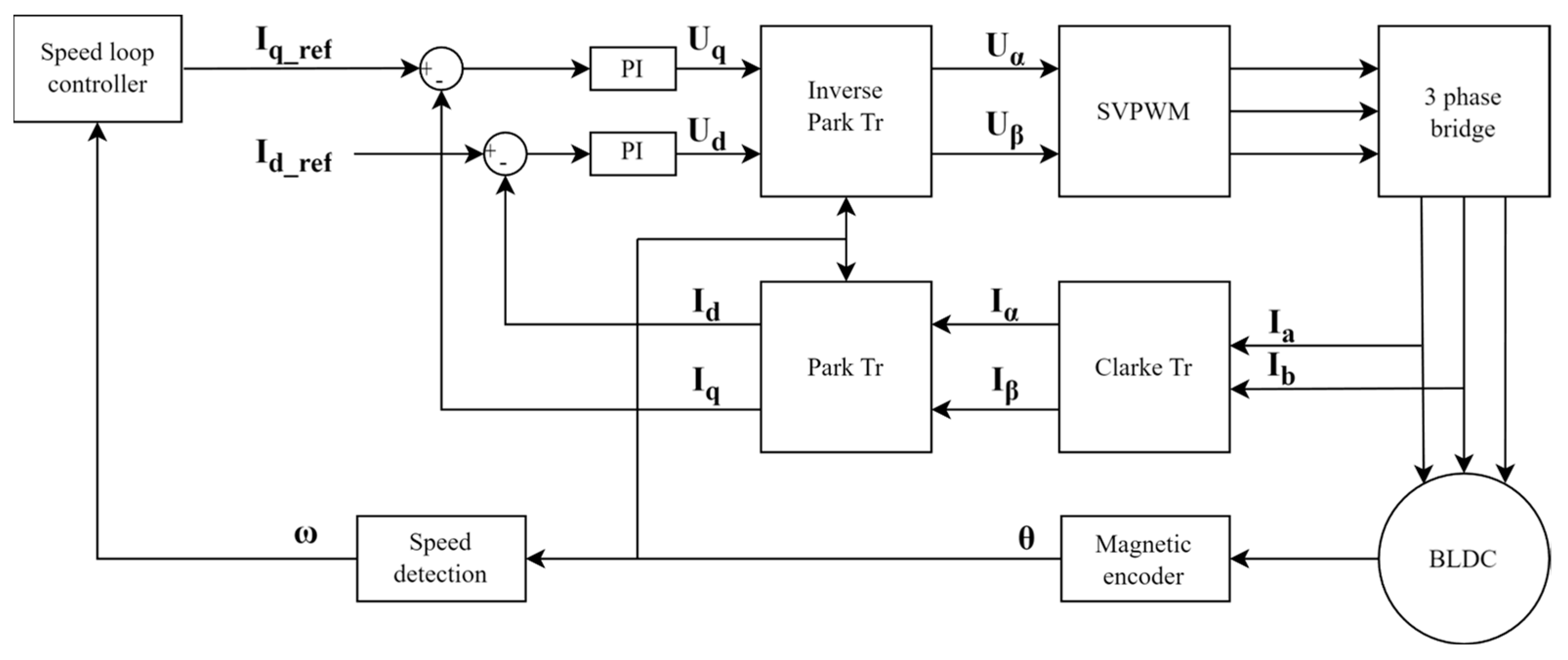
2.1. Working Principle of FOC

The FOC driver of BLDC is mainly composed of Clarke transformation, Park and inverse Park transformation, SVPWM, and a current loop controller. The block diagram of the control structure is shown in Figure 1:
Figure 1 consists of three parts: a FOC controller, a three-phase full-bridge power drive circuit, and a three-phase DC brushless motor.
The internal structure of the BLDC is composed of three sets of coils connected in a Y-shape. The current passes through the internal coil winding of the motor to generate a magnetic field, which drives the permanent magnet to rotate and completes the motor’s rotational movement. Taking the current inflow as positive and the outflow as negative, the sum of the three phase currents of the motor is zero, as shown in Equation (1):
I a + I b + I c = 0
Therefore, it is only necessary to collect two-phase currents I a and I b when sampling the current, and then complete the calculation of I c through Equation (1). Due to the characteristics of the SVPWM drive, three sinusoidal alternating currents with a phase difference of 2π/3 can be obtained by sampling the current of the BLDC. According to the FOC control theory [25], the three-phase sinusoidal current with equal amplitude can be converted into a two-phase orthogonal sinusoidal current by using the Clarke transformation of Equation (2):
I α I β = 2 3 1 1 2 1 2 0 3 2 3 2 I a I b I c
The Clarke transformation does not change the frequency or amplitude of the current during the process of completing the orthogonalization of the phase current. The transformed sine wave current still varies with the motor angle. The flux linkage decoupling can be completed through the Park transformation of Equation (3). To transform two-phase quadrature sine wave current signals into quadrature DC signals:
I d I q = c o s θ s i n θ s i n θ c o s θ I α I β
Among them, I d is along the radial direction of the permanent magnet rotor, and I q is along the tangential direction of the permanent magnet rotor. The torque of the DC motor is directly proportional to the current, and the torque in these two directions can be controlled independently through the reference value. The angle during the movement of the BLDC can be estimated by the Kalman filter or measured by a magnetic encoder. In this paper, we have chosen a BLDC with a magnetic encoder that can generate both sine and cosine signals. By calculating the arctangent of these two signals, the actual angle of BLDC can be obtained. And according to the BLDC angle information, the BLDC speed can be calculated [3]. The I q _ r e f is calculated from the reference speed and actual speed of the BLDC by the PI controller, and the I d _ r e f usually set to zero. The decoupled feedback current I d and I q , and the reference current I d _ r e f and I q _ r e f , are PI adjusted to calculate the control amount. Then drive the BLDC through Park inverse conversion and SVPWM to complete the current closed loop.

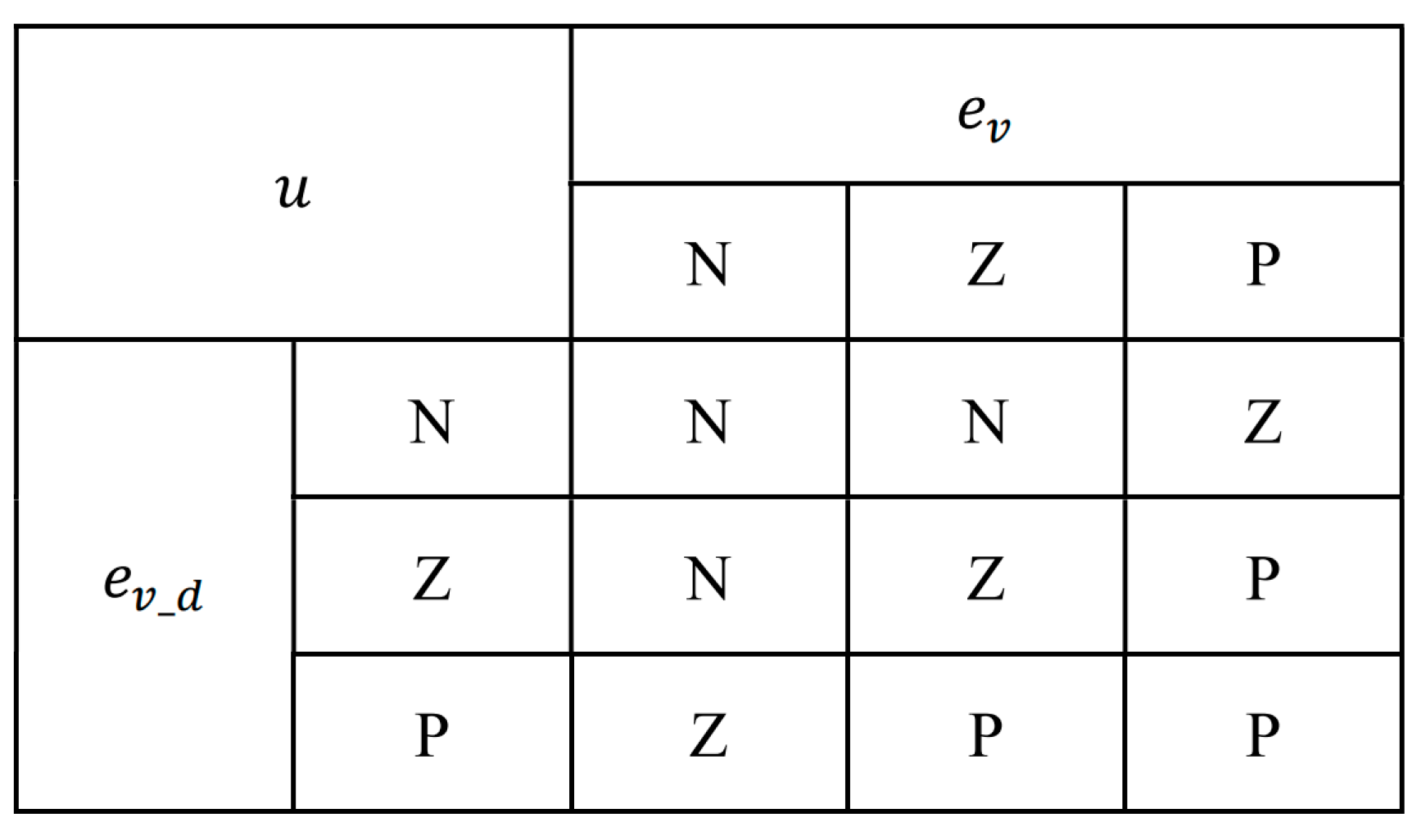
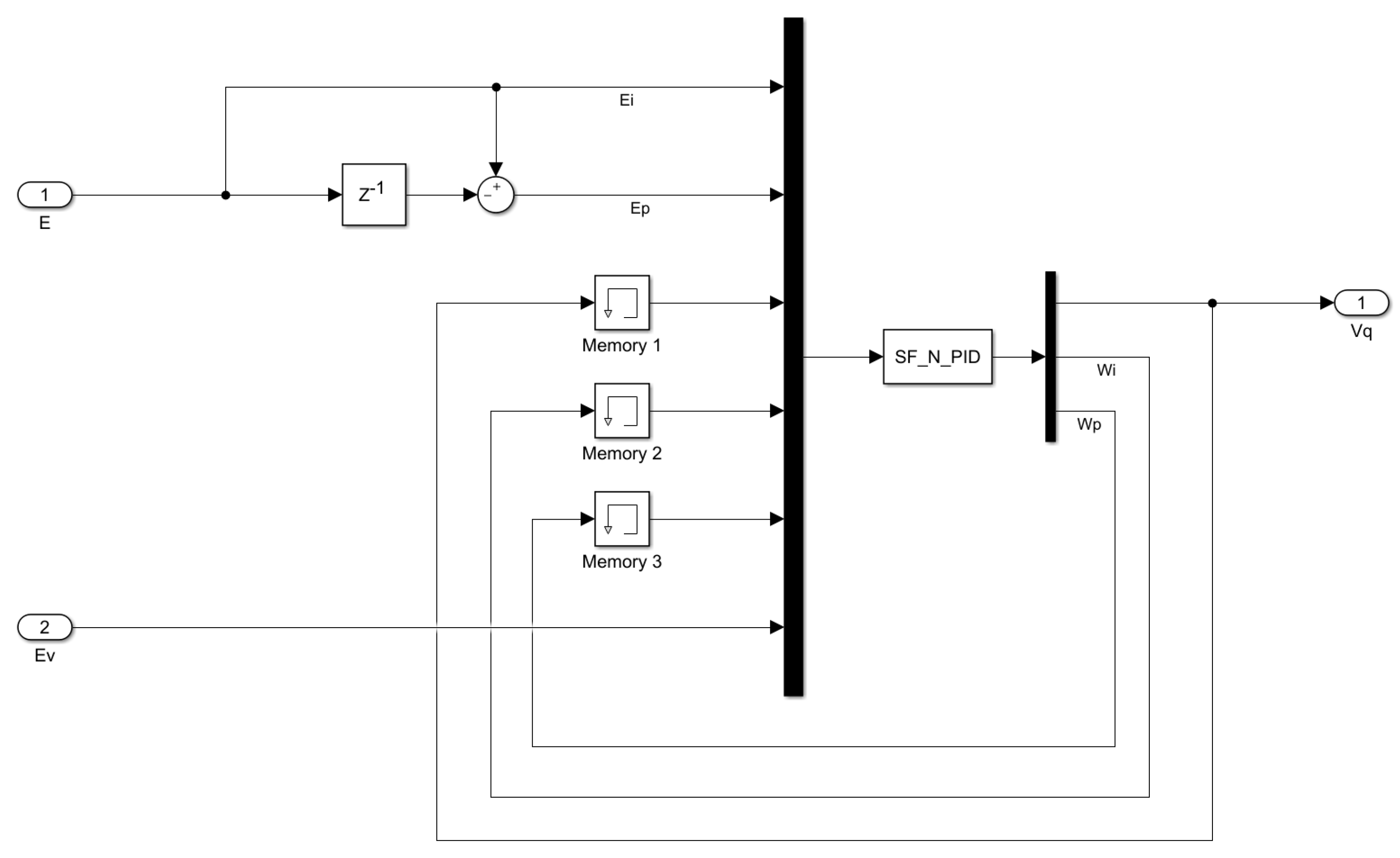
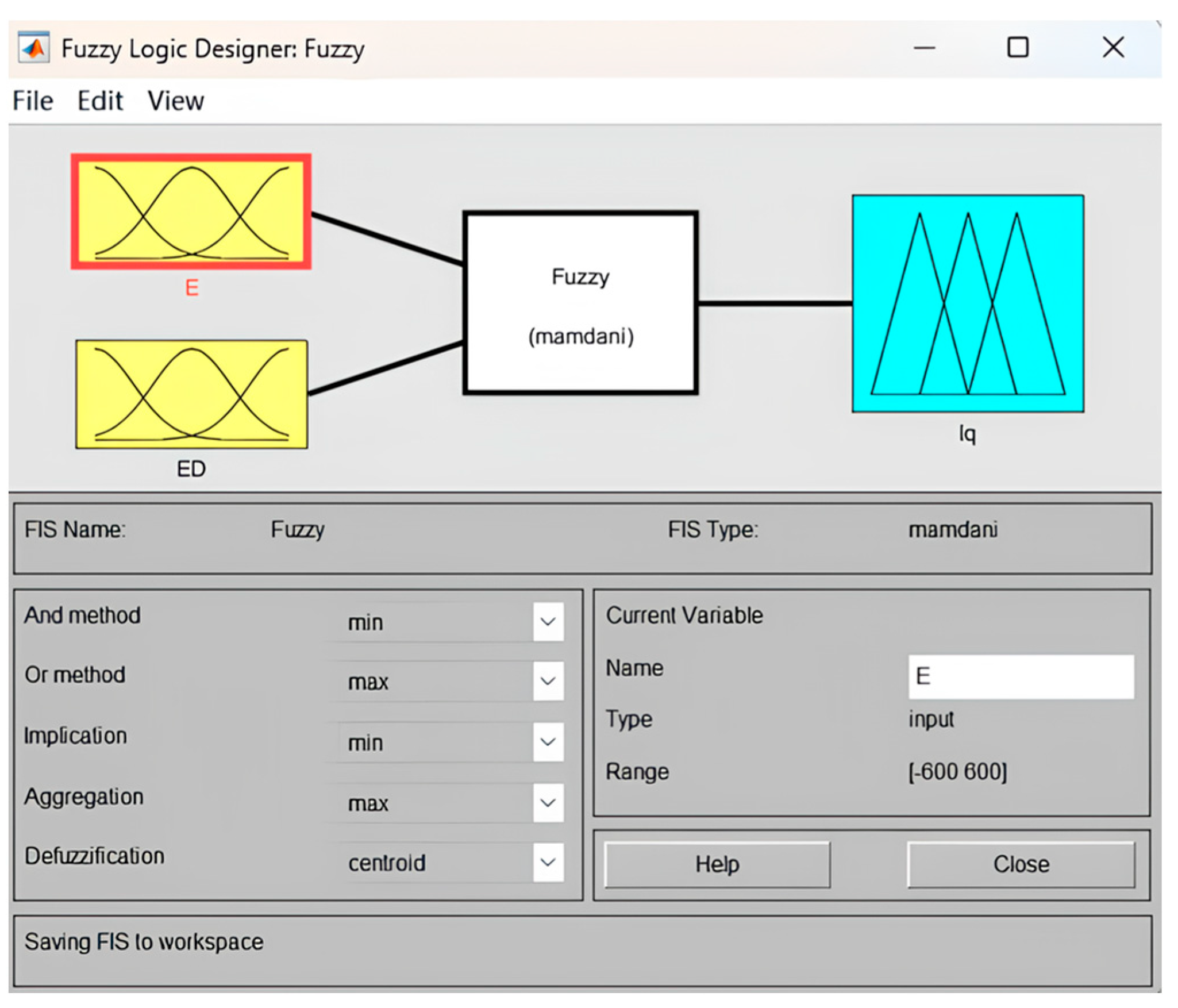
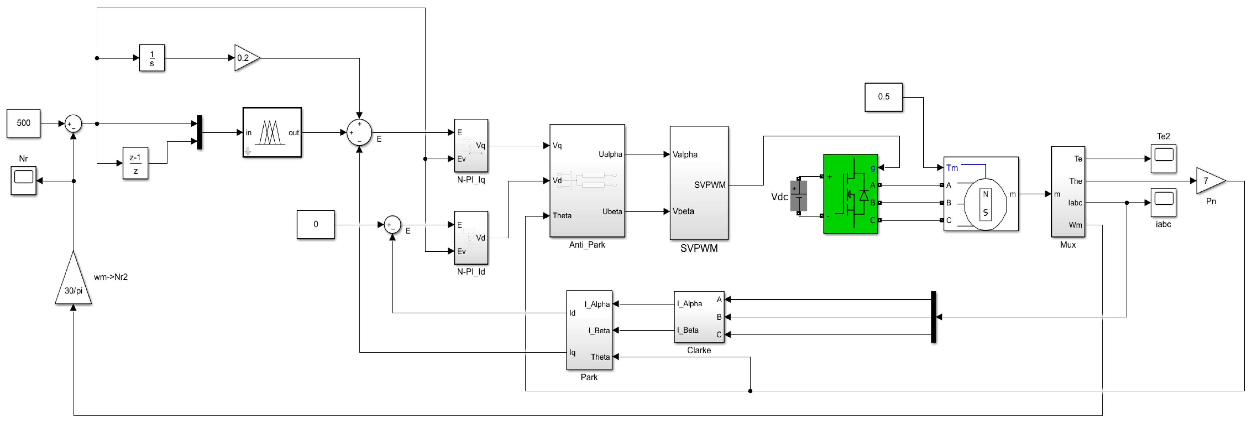
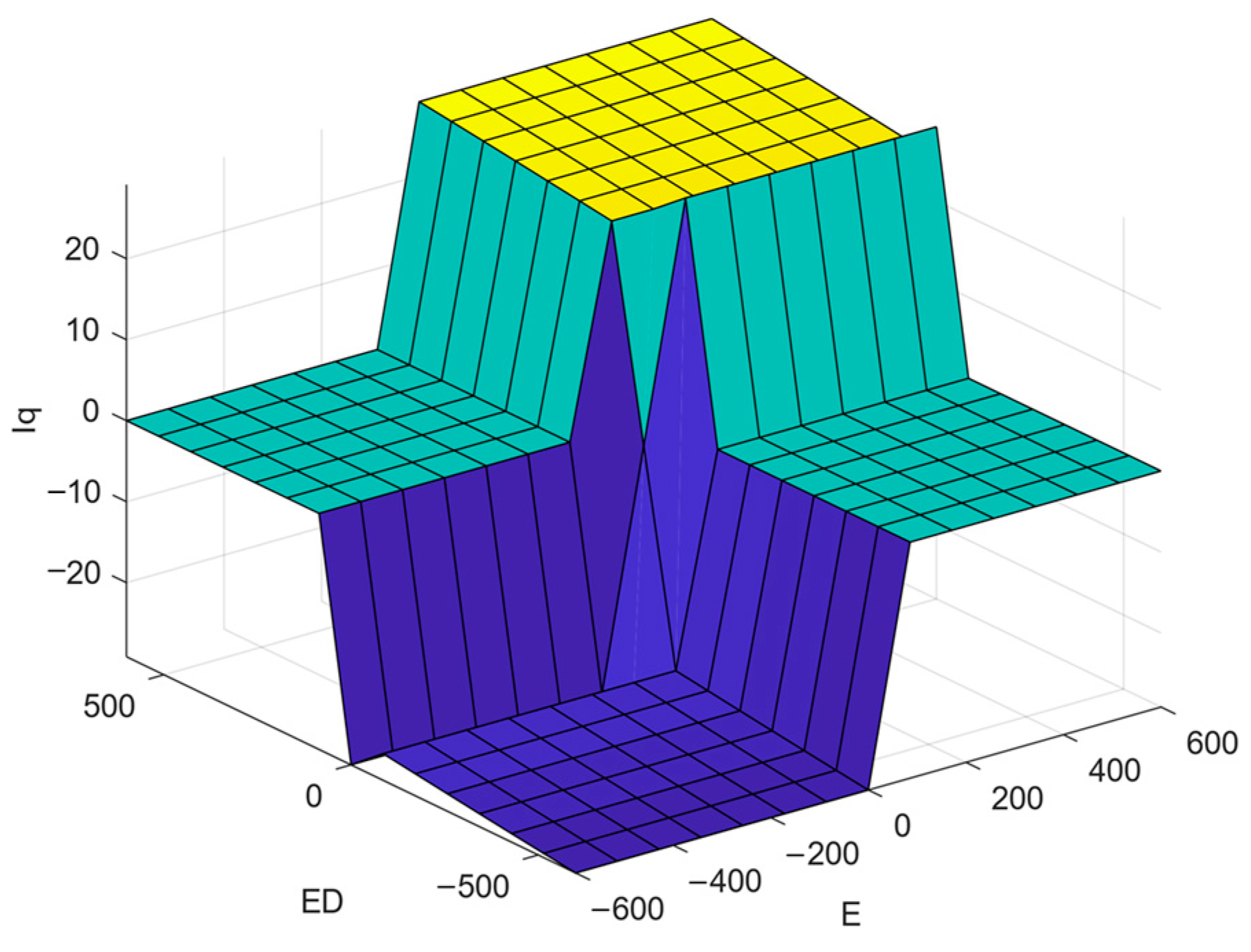
2.2. Design of Fuzzy Integral-Neuron PI Double-Loop Controller

BLDC is an electromechanical unit that controls the torque of the motor through the drive current and then controls its rotational acceleration. Parallel platforms require servo drives to complete BLDC constant-speed control. Usually, the double closed-loop control strategy of speed loop + current loop is used, as shown in Figure 1.
The traditional FOC controller uses two PI controllers to complete the speed and current closed-loop, respectively, and because the parameters have to be adjusted several times to achieve better control, the tuning process is cumbersome [26]. It is difficult to achieve good control results by using constant PI parameter in the case of load changes. In order to improve the control performance of the servo driver, the parameter tuning process of the PI controller is simplified, and the adaptability to load changes is enhanced. Based on the original double PI controller, a fuzzy integral-neuron proportional-integral double-loop controller (FI-NPI) is proposed. The BLDC current loop adds a neuron structure to the original PI controller to realize the online adjustment of PI parameters. The fuzzy integral controller is used to complete the closed-loop control of the BLDC speed regulation, which makes the controller independent of the system model and has strong robustness and stability. Compared with the PI velocity closed-loop method, its response time is shorter.
The control precision of the fuzzy controller is not high, and there are steady-state errors. Therefore, the system structure adds an integrator on the basis of the fuzzy controller to improve the control accuracy and eliminate the steady-state error. The structure of the FI-NPI controller is shown in Figure 2:
In Figure 2, the neuron PI controller of the current loop can complete the dynamic adjustment of PI parameters through input, output, and error parameters [27]. Assuming that the two input quantities of the neuron are x p and x i , respectively, and the current loop error is e i , then the neuron input satisfies Equation (4):
x p k = e i k e i k 1 x i k = e i k
Let w p and w i be the proportional and integral control parameters of the PI controller, respectively. According to the incremental PI control algorithm [28], the system output control quantity is given by Equation (5):
u k = u k 1 + K w p k x p k + w i k x i k
Among them, the coefficient K is a constant value. The online update of parameters w p and w i adopt the supervised Hebb learning rule [29]. And the speed loop error e v is introduced as the teacher signal through the feedforward branch, and the learning algorithm is shown in Equation (6):
w p k + 1 = w p k + η p x p k u k e v k w i k + 1 = w i k + η i x i k u k e v k
It can be seen from Equation (6) that when the speed loop error e v , current loop error e i , and current loop output u get large, the PI controller parameters w p and w i will increase accordingly. As the error and output decrease, the PI controller parameters decrease accordingly. In BLDC control system, current loop is used to accelerate the convergence of speed loop, so the error of the speed loop can be used as the teacher signal to achieve better results. Besides, the integrator in the speed loop will weaken the dynamic response of current loop, and the speed loop error e v also can be used as a feedforward signal to enhance the dynamic response of current loop. When the output error or control amount is large, the system will increase the PI parameter to accelerate the system convergence. When the error decreases, the controller will reduce the PI parameter accordingly to make the system overshoot smaller. In order to avoid the two situations where the PI controller parameters w p and w i calculated by the neuron are too large, causing system oscillation and the calculated negative value causes the system to diverge. We limit the valid value ranges of w p and w i in the neuron learning rules. Specifically, the boundaries of the parameters that can be set during manual tuning were selected as the range of valid values for neuron learning to ensure the stability of the system.
The speed-loop–fuzzy-controller is mainly composed of input fuzzification, fuzzy reasoning, and output defuzzification [30]. The input fuzzification of this system adopts the commonly used classification fuzzy set method, and the output defuzzification adopts the centre of gravity method to make output smoothly. Let the BLDC rotational speed error be e v , and the difference of rotational speed error be e v _ d . The domain classification of the fuzzy controller will affect the output accuracy of the controller, and theoretically, the more domain divisions, the higher the output accuracy, but it will increase the complexity of the program. The BLDC controller is based on an embedded platform with limited computing power. Therefore, in the case of satisfying the accuracy requirements, the fewer domain divisions, the better. For the balance of precision and computing power, we divide the domain of input and output into three levels: positive (P), zero (Z), and negative (N). Then, build fuzzy control rules, as shown in Figure 3:
The input and output of fuzzy control are both fuzzy quantities, so the fuzzy control method will inevitably have steady-state errors. In order to improve the precision of BLDC speed closed-loop control, an integrator output is superimposed on the output of fuzzy control to form a fuzzy integral controller. This control structure can make full use of the advantages of the strong robustness and fast convergence speed of the fuzzy controller while ensuring the control accuracy.

3. Experiments and Results

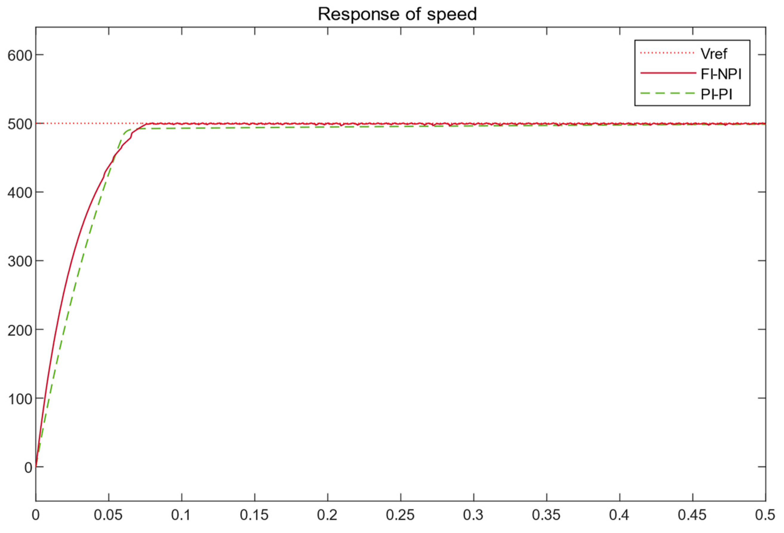
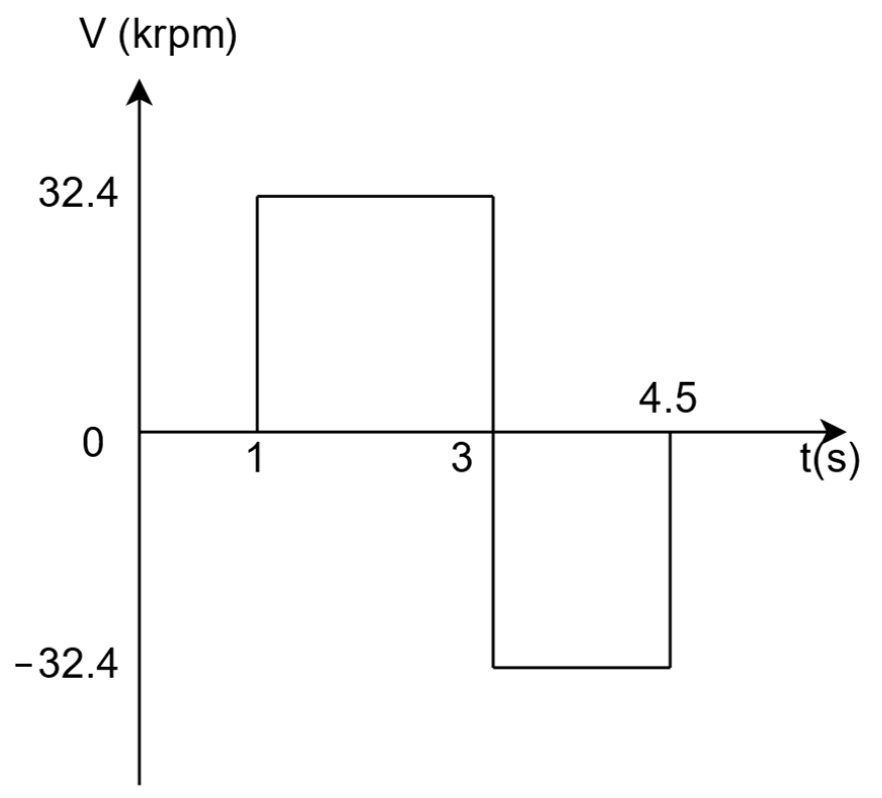
3.1. Simulation Experiment
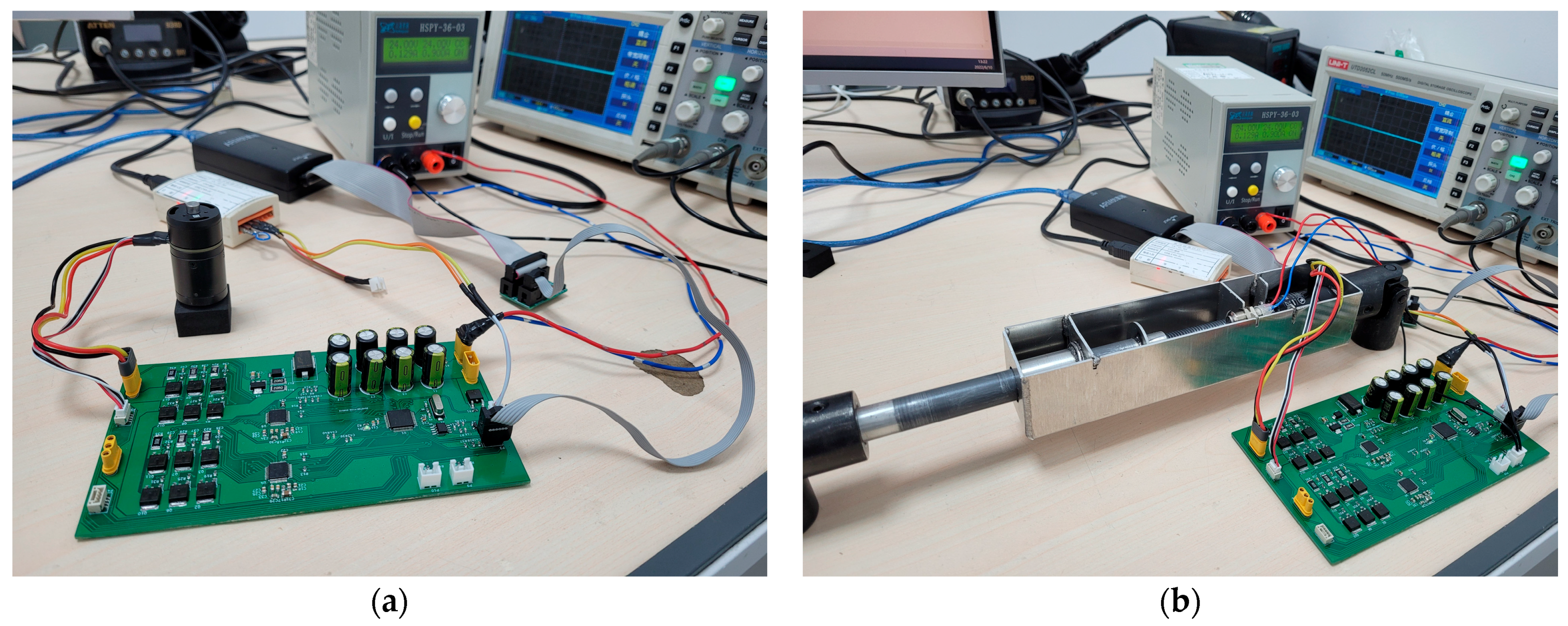
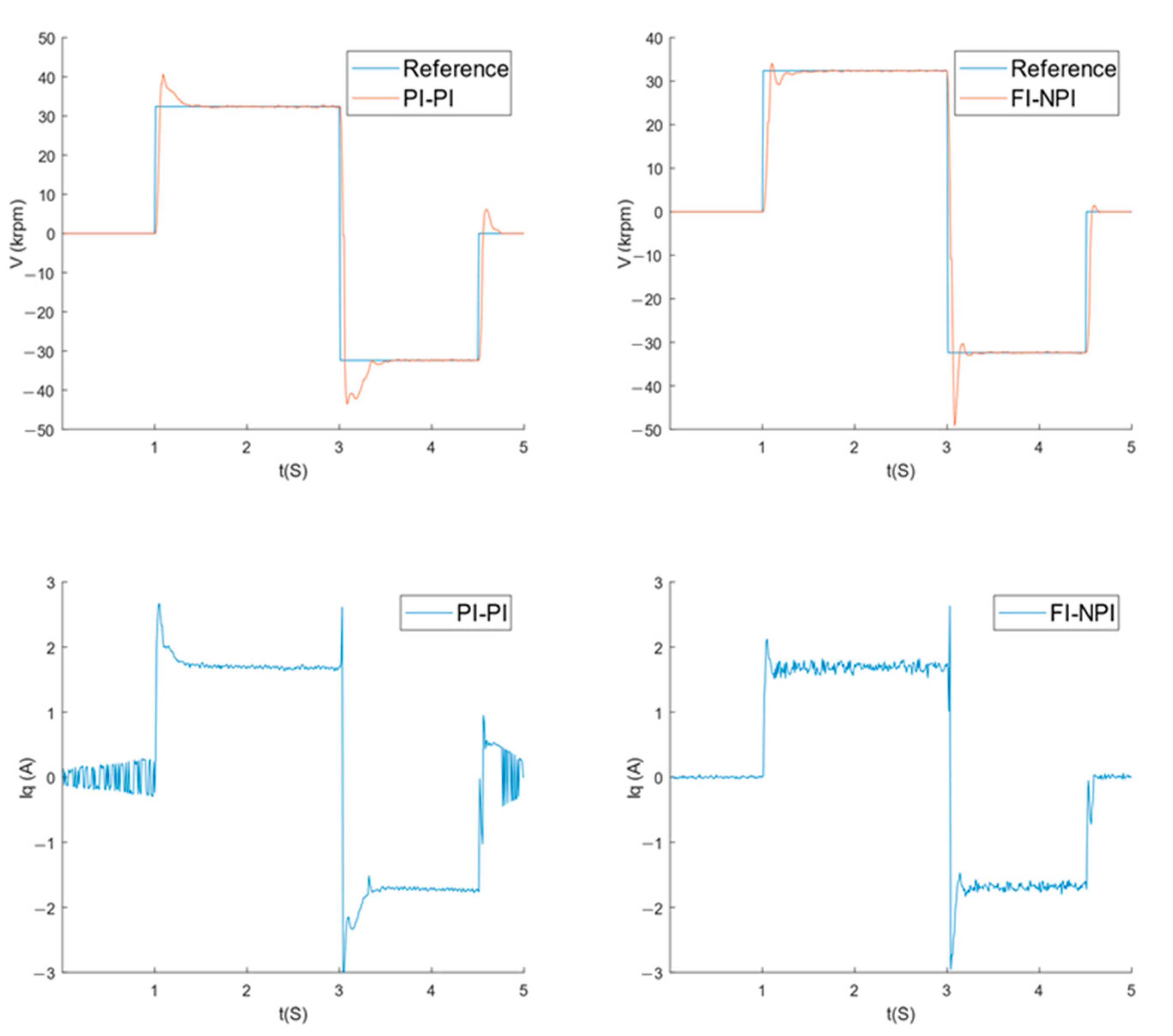
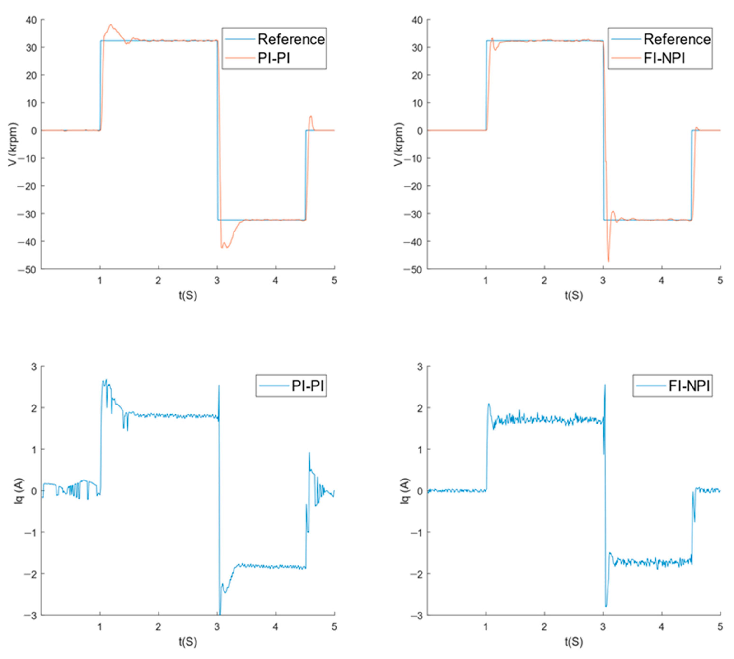
In order to verify that the FI-NPI dual-loop controller can effectively complete the brushless DC speed regulation closed-loop control task and compare the control effect with the traditional dual-PI speed closed-loop controller, this paper uses the Simulink toolbox to carry out simulation experiments on MATLAB Version 9.2 (R2018b) to build corresponding simulation modules for each component of the driver. Figure 4 shows the overall simulation structure block diagram.
The structural block diagram in Figure 4 is mainly composed of the FI speed loop controller, NPI current loop controller, FOC control component, three-phase full-bridge power module, and BLDC. Among them, the FOC control component is composed of the Clarke transformation, Park transformation, reverse Park transformation, and SVPWM. The reference target rotational speed of the experimental setup is 500 rpm. The structure of the SVPWM space voltage vector synthesis algorithm is relatively complicated, which consists of four parts: sector calculation, vector action time calculation, PWM time calculation, and PWM waveform generator. In order to make the simulation as similar as possible to the physical performance, the settings of the simulation parameters are consistent with the physical system. We set the simulated DC bus voltage to 24 V. The PWM modulation frequency used to drive the three-phase full bridge is set to 10 kHz. The specific implementation of the SVPWM simulation component is shown in Figure 5:
The neuron PI controller is relatively complicated because of the logic structure and operation involved. It is rather cumbersome to realize by means of a structural block diagram. Therefore, the neuron PI controller is implemented by writing the S function. The block diagram of the simulation structure is shown in Figure 6:
It can be seen from Figure 6 that there are 6 neuron PI controller inputs. They are: integral error x i k ; proportional error x p k ; last moment output u k 1 ; integral coefficient w i k 1 ; proportional coefficient w p k 1 ; and the velocity error e v k as a teacher signal. Memory1 to Memory3 components are all memories, used to store the output value at the last moment. According to Equations (4)–(6), write the corresponding code in the S function file. The integral coefficient w i k and proportional coefficient w p k at the current moment are calculated from the input of the S function and Limited to the correct value range. Finally, the incremental PI control algorithm is completed to calculate the output u k at the current moment.
Based on the current closed loop, the real-time speed of the motor is measured. The feedback control can realize the speed-closed loop and achieve the double-closed loop control effect. The fuzzy integral controller designed in this system consists of two parts: a fuzzy controller and an integrator. Among them, the design of the integrator is relatively simple, which can be completed directly by the integral operation multiplied by an integral coefficient. The total output is obtained by superimposing the output control quantity of the integrator with the output control quantity of the fuzzy controller. The structure block diagram is shown in Figure 7:
A fuzzy controller needs to determine the input domain, output domain, and fuzzy inference rules. The design of the fuzzy controller is completed using the fuzzy toolbox under the MATLAB platform, and the design interface is shown in Figure 8:
The controller input is the speed error e v and the difference e v _ d between the speed error and the error at the previous moment. In this experiment, the input ranges of e v and e v _ d are both ± 600 rpm. The domain of discourse is divided into three levels: negative (N), zero (Z), and positive (P). For the speed error e v , the membership function of N and P is set as trapezoidal membership function (trapmf), and the membership function of Z is triangular membership function (trimf). For the difference e v _ d of the speed error, the membership functions of N, Z, and P are all triangular membership functions (trimf).
When in the speed closed loop, the control quantity of the fuzzy controller is the rotor tangential reference current I q _ r e f . The control volume defuzzification method uses the center of gravity method. Considering the motor and power supply load parameters, the output range of the set current is ±30 A. The domain of discourse is divided into three levels: negative (N), zero (Z), and positive (P). The membership function of N and P is set as trapezoidal membership function (trapmf), and the membership function of Z is the triangular membership function (trimf).
According to the BLDC speed fuzzy control rules in Figure 3, the fuzzy control rule library of the simulation platform is established. The fuzzy control map is shown in Figure 9:
It can be seen from the design process of the fuzzy controller that the key points of the controller design are determining the data range of input and output, selecting the membership function, and the fuzzy inference rule base. Once this is determined, a control law that meets the expectations can be designed. Compared with the PI controller, the fuzzy controller design process is more complex, but the process of manual parameter tuning is simplified.
The current flowing in the radial direction of the rotor of the motor does not generate the torque to rotate the motor. Therefore I d _ r e f is usually set to 0 under non-field weakening conditions. The parameters of the controlled BLDC in the simulation environment are selected from the parameters of the actual controlled object, the Robomaster M2006 P36 three-phase brushless DC motor in the servo system. The specific parameter values are from the motor manual, as shown in Table 1:
The model and algorithm are simulated in the Simulink simulation environment. In order to test the control effect of the FI-NPI double-loop controller, a double PI controller was added as a control group. The target speed is set to 500 rpm, and the image of the speed closed loop using the double PI controller and the FI-NPI double loop controller is shown in Figure 10:
It can be seen from Figure 10 that the FI-NPI dual-loop controller can complete the BLDC speed closed-loop control as expected.

3.2. Practical Test

In order to test the performance of the FI-NPI double-loop controller on an actual servo drive, the neuron PI control algorithm and fuzzy integral control algorithm of MATLAB simulation are implemented in the C language to replace the original current loop and speed loop PI controller in the lower computer software. The BLDC operating load is not considered in the simulation. However, in practical use, the friction of the manipulator will affect the dynamic performance of the BLDC motor to a certain extent. Specifically, the rotation of the BLDC will drive the expansion and contraction of the robotic arm, which will cause a significant change in the friction of the connecting rod of the robotic arm. In order to verify the robustness of the FI-NPI algorithm, the physical experiment carried out the speed closed-loop test on the two conditions of BLDC no-load and load with manipulator. This is shown in Figure 11:
In order to accurately measure the relevant performance index parameters of the controller, avoid the consistency error caused by the manual operation of the upper computer to start and stop the motor. The host computer software is written under the Qt platform so that it can automatically set the reference speed according to the speed sequence and record the RMSE of the closed-loop speed. The speed control sequence is: the initial motor is in a stopped state, and when it is 1 s, the motor rotates forward; at 3 s, the motor switches to reverse; at 4.5 s, stop the motor. The reference speed change sequence is shown in Figure 12:
Use the host computer software to record the BLDC rotation speed and the current of q-axis every 10 mS. Figure 13 shows the control effect of the dual PI controller and FI-NPI controller on the BLDC motor without load:
As can be seen from Figure 13, both the dual PI controller and the FI-NPI can achieve speed closed-loop control, but the PI controller takes significantly longer to reach a steady state. It can also be seen from the q-axis current image that the current control performance of the FI-NPI algorithm is better than that of the dual-PI controller.
Since the embedded system cannot measure a true negative current, a bias voltage is added to the measured current, and fluctuations in the voltage regulator and noise in the current feedback loop can cause the feedback current to be detected before the motor is even running. Therefore, the PI controller counteracts the disturbance by adjusting the Iq current. As can be seen in Figure 13, the Iq current exists before the motor starts running. For the FI-NPI controller, when the speed error is 0, the PI controller coefficient does not increase because the speed error is the teacher signal of the current loop. As a result, there is no significant Iq current value before the motor is running. When the velocity error is detected, the parameters of the PI controller are increased according to Equation (6) so that the system converges quickly. As can be seen from the large current fluctuations of FI-NPI in Figure 13 when the motor is running, the parameters of NPI are larger. When the BLDC stops, the NPI parameter becomes smaller again, so the Iq oscillation of the NPI after the motor is stopped is less than that of the dual PI controller.
The dynamic tuning strategy of current loop also has a certain impact on the speed loop: the overshoot of FI-NPI is greater than that of the dual-PI controller. The reason for this phenomenon is that the Iq_ref calculated by the velocity loop is relatively large before the error of the fuzzy controller reaches the Z-zone, and since the control cycle of the current loop is much shorter than that of the velocity loop, the NPI current loop will perform multiple closed-loop control with larger PI parameters. Since the fuzzy controller no longer works after the speed loop error reaches the Z-zone, there will be some slight oscillations caused by the integrator.
The control effects of the BLDC after loading are shown in the Figure 14:
As can be seen, the output waveform does not change much when there is a load and there is no load. We recorded the RMSE of all the tests, and results are shown in the Table 2:

4. Discussion

In this paper, we introduce a novel double-loop control structure called FI-NPI (fuzzy integral and neuron proportional integral) double-loop controller to realize the double-closed-loop control task of the servo current and speed of the BLDC motor. Our control structure introduces a neural structure in the current loop and a fuzzy integral controller in the speed loop so as to achieve the purpose of simplifying the parameter tuning of the double closed-loop controller and improving its adaptability to load changes. Theoretically, comparing our controller with a traditional dual-PI controller, the following conclusions are obtained: in the speed loop, fuzzy controller is more flexible with better dynamic characteristics and integrator can eliminate the steady-state error of fuzzy controller; in the current loop, the neuron PI controller can be dynamically adjusted to achieve fast convergence for large errors and small overshoot for small errors. In addition, unlike other advanced control strategies, our method does not require an accurate control model of the BLDC, so it can be used in different types of BLDC control.
Through simulations in the Simulink environment of MATLAB, we observe that the FI-NPI dual-loop controller performs well in closed-loop control of BLDC speed. At the beginning of the simulation, because the input fuzzy quantity of the fuzzy controller does not reach the Z universe, the fuzzy controller maintains a large control quantity. This leads to an increase in the PI parameter of the current loop, which makes the dynamic response speed of the FI-NPI dual-loop controller better than that of the traditional dual-PI controller at the beginning of the simulation. As the speed error decreases, the input fuzzy quantity of the fuzzy controller enters the Z universe, and the controller output decreases gradually, which reduces the overshoot of the system. The results show that the convergence rate of the FI-NPI controller is better than that of the dual PI controller, and there is no steady-state error in the steady state.
In the physical test, we further compare the FI-NPI double-loop controller with the conventional dual-PI controller. The results show that although the traditional dual-PI controller can reach steady state, it shows a long adjustment time in the closed-loop control of speed and a large overshoot in the closed-loop control of current. In contrast, the FI-NPI double-loop controller not only completed the speed tracking task as expected, but also had a small overshoot in current loop. In terms of control accuracy, the RMSE of the FI-NPI dual-loop controller is better than that of the dual-PI controller under both no-load and on-load conditions. In addition, since the new method essentially consists of a PID-like speed loop controller and a current loop PI controller with auto-tuning parameters, the stability of the new controller is the same as that of the commonly used dual PI controllers.
Our research results and the existing literature support the application of fuzzy control and neural architecture in motor control [31,32]. However, it is worth noting that there are still some limitations in this study. For example, we did not consider the load of BLDC operation during simulation, but in practical use, the friction force of the manipulator will affect the BLDC dynamic performance to some extent. Future research: We can further explore the performance of the FI-NPI controller under different working conditions and environments, as well as optimize the fuzzy controller design. In addition, the comparison with other advanced control methods is also a direction worthy of further research.
In general, our study provides a new and effective method for the double closed-loop control of BLDC motors, and its performance superiority is verified in the experiment, which provides a new idea for the future development of the field of intelligent motor control.

5. Conclusions

In this study, we introduce an innovative FI-NPI (Fuzzy Incremental-Neural Network Proportional-Integral) dual-loop control structure to successfully complete the double closed-loop task of the servo current and speed of the BLDC motor. This structure cleverly uses the control advantages of fuzzy controller and integrator, and uses the speed error as the teacher signal of neuron supervised learning through the feedforward branch to improve the effect of speed closed-loop control. The neuronal structure can also realize the dynamic adjustment of the PI parameters of the current loop. Then we build the system in the Simulink toolbox, and compare the FI-NPI controller with the traditional PI controller. Experimental results show that the FI-NPI controller has faster dynamic response speed. In order to further verify the effectiveness of the controller in the actual system, we implemented the FI-NPI controller in C language in the servo-driven lower computer, and performed the speed closed-loop test in two scenarios of no-load and on-load of the BLDC motor. The experimental results show that the FI-NPI double-loop controller is superior to the double PI controller in performance indicators such as overshoot and RMSE, which proves that it is an advanced method more suitable for brushless DC servo control.
In future research, we will further expand the application scope of the dynamic control of the parallel platform to adapt to more complex robotic systems. At the same time, we will continue to optimize the FI-NPI control structure and explore the fusion of more machine learning and neural network methods to further improve the accuracy and robustness of servo control. Furthermore, we will focus on implementing controllers that do not require much pre-training to improve applicability in resource-limited environments.

Author Contributions

Conceptualization, Q.G. and W.Z.; methodology, J.T. and L.Y.; software, Q.G. and S.L.; formal analysis, J.T. and Z.Y.; writing—original draft preparation, R.W., S.L. and L.Y.; writing—review and editing, R.W., W.Z. and L.Y.; funding acquisition, W.Z. All authors have read and agreed to the published version of the manuscript.

Funding

Supported by Sichuan Science and Technology Program (2023YFSY0026, 2023YFH0004).

Data Availability Statement

Data are contained within the article.

Conflicts of Interest

The authors declare no conflicts of interest.

References

  1. Yuan, X.; Tang, Y.; Wang, W.; Zhang, L. Parametric Vibration Analysis of a Six-Degree-of-Freedom Electro-Hydraulic Stewart Platform. Shock Vib. 2021, 2021, 9994786. [Google Scholar] [CrossRef]
  2. Li, J.; Nie, Z.; Chen, Y.; Ge, D.; Li, M. Development of Boom Posture Adjustment and Control System for Wide Spray Boom. Agriculture 2023, 13, 2162. [Google Scholar] [CrossRef]
  3. Gu, Q.; Tian, J.; Yang, B.; Liu, M.; Gu, B.; Yin, Z.; Yin, L.; Zheng, W. A novel architecture of a six degrees of freedom parallel platform. Electronics 2023, 12, 1774. [Google Scholar] [CrossRef]
  4. Zhang, F.; Mei, J.; Zhao, Y. Dimensional synthesis of six-degrees-of-freedom high-speed parallel robot using comprehensive evaluation index. J. Mech. Sci. Technol. 2020, 34, 1325–1338. [Google Scholar] [CrossRef]
  5. Ding, Y.; Zhu, X.; Sun, X.; Zhang, J.; Chen, X. Soft Sensor Simulation of Minimum Energy Consumption of Joint Manipulator Drive System Based on Improved BP Neural Network. In Proceedings of the 4th International Conference on Electrical, Automation and Mechanical Engineering (EAME), Electr Network, Turin, Italy, 21–22 June 2020. [Google Scholar]
  6. Xu, H.; Zhou, H.; Tan, S.; Duan, J.-A.; Hou, F. A six-degree-of-freedom compliant parallel platform for optoelectronic packaging. IEEE Trans. Ind. Electron. 2020, 68, 11178–11187. [Google Scholar] [CrossRef]
  7. Wang, W.; Wang, N.; Wu, X. Kinematics and dynamics analysis of a six-degree of freedom parallel manipulator. Int. J. Adv. Robot. Syst. 2022, 19, 17298806221132077. [Google Scholar] [CrossRef]
  8. Kausar, Z.; Shah, M.F.; Masood, Z.; Rehman, H.Z.U.; Khaydarov, S.; Saeed, M.T.; Razmkhah, O.; Yaqoob, H. Energy efficient parallel configuration based six degree of freedom machining bed. Energies 2021, 14, 2642. [Google Scholar] [CrossRef]
  9. Sakama, S.; Tanaka, Y.; Kamimura, A. Characteristics of hydraulic and electric servo motors. Actuators 2022, 11, 11. [Google Scholar] [CrossRef]
  10. Baballe, M.A.; Bello, M.I.; Umar, A.A.; Shehu, A.K.; Bello, D.; Abdullahi, F.T. Different Types of Servo Motors and Their Applications. In Proceedings of the 1st International Conference on Engineering and Applied Natural Sciences, Konya, Turkey, 10–13 May 2022; pp. 974–979. [Google Scholar]
  11. Hans, S.; Ghosh, S. Position analysis of brushless direct current motor using robust fixed order H-infinity controller. Assem. Autom. 2020, 40, 211–218. [Google Scholar] [CrossRef]
  12. Anshory, I.; Robandi, I.; Wirawan, W. Parameters identification BLDC motor: Instrumentations and transfer functions. In Proceedings of MATEC Web of Conferences; EDP Sciences: Les Ulis, France, 2018; p. 11012. [Google Scholar]
  13. Murali, M.; Arulmozhiyal, R. Investigation on modeling and simulation BLDC motor fed universal actuation system. Rev. Int. De Métodos Numéricos Para Cálculo Y Diseño En Ing. 2021, 37, 1–8. [Google Scholar] [CrossRef]
  14. Jigang, H.; Hui, F.; Jie, W. A PI controller optimized with modified differential evolution algorithm for speed control of BLDC motor. Autom. Časopis Za Autom. Mjer. Elektron. Računarstvo I Komun. 2019, 60, 135–148. [Google Scholar] [CrossRef]
  15. Dat, N.T.; Van Kien, C.; Anh, H.P.H. Optimal FOC-PID parameters of BLDC motor system control using parallel PM-PSO optimization technique. Int. J. Comput. Intell. Syst. 2021, 14, 1142–1154. [Google Scholar] [CrossRef]
  16. Ali, T.; Lin, H.; Wang, Z.K. Design and Simulation of Novel Control Architecture for the Movement of Commercial Aircraft Cabin Door. In Proceedings of the 16th IEEE International Computer Conference on Wavelet Active Media Technology and Information Processing (ICCWAMTIP), Univ Elect Sci & Technol China, Chengdu, China, 13–15 December 2019; pp. 400–405. [Google Scholar]
  17. Alzuabidi, O.; Abdulsada, M.A.; Hussein, M.W. Analysis and Modeling of Brushless DC Motor PWM Control Technique Using PSIM Software. In Proceedings of the 2nd International Conference on Emerging Technologies and Intelligent Systems (ICETIS), Electr Network, 3 September 2023; pp. 225–234. [Google Scholar]
  18. Zhang, Z.; Li, Y. An AEFA-Based Optimum Design of Fuzzy PID Controller for Attitude Control Flywheel with BLDC Motor. Aerospace 2022, 9, 789. [Google Scholar] [CrossRef]
  19. Intidam, A.; El Fadil, H.; Housny, H.; El Idrissi, Z.; Lassioui, A.; Nady, S.; Jabal Laafou, A. Development and Experimental Implementation of Optimized PI-ANFIS Controller for Speed Control of a Brushless DC Motor in Fuel Cell Electric Vehicles. Energies 2023, 16, 4395. [Google Scholar] [CrossRef]
  20. Lee, S.; Son, H. Six Steps Commutation Torque and Dynamic Characteristics of Spherical Brushless Direct Current Motor. IEEE Trans. Ind. Electron. 2023, 71, 5045–5054. [Google Scholar] [CrossRef]
  21. Patel, H.; Chandwani, H. Simulation and experimental verification of modified sinusoidal pulse width modulation technique for torque ripple attenuation in Brushless DC motor drive. Eng. Sci. Technol. Int. J. 2021, 24, 671–681. [Google Scholar] [CrossRef]
  22. Hussein, T.A.; Mohammed, L.A. Detailed Simulink implementation for induction motor control based on space vector pulse width modulation SVPWM. Indones. J. Electr. Eng. Comput. Sci 2021, 22, 1251–1262. [Google Scholar] [CrossRef]
  23. Chinmaya, K.; Singh, G.K. Experimental analysis of various space vector pulse width modulation (SVPWM) techniques for dual three-phase induction motor drive. Int. Trans. Electr. Energy Syst. 2019, 29, e2678. [Google Scholar] [CrossRef]
  24. Siddique, N. Fuzzy Control. In Intelligent Control. Studies in Computational Intelligence; Springer: Cham, Switzerland, 2014; Volume 517. [Google Scholar] [CrossRef]
  25. Meng, F.; Hu, Y.; Ma, P.; Zhang, X.; Li, Z. Practical Control of a Cold Milling Machine using an Adaptive PID Controller. Appl. Sci. 2020, 10, 2516. [Google Scholar] [CrossRef]
  26. Wang, F.; Zhang, Z.; Mei, X.; Rodríguez, J.; Kennel, R. Advanced control strategies of induction machine: Field oriented control, direct torque control and model predictive control. Energies 2018, 11, 120. [Google Scholar] [CrossRef]
  27. Wang, Y.-G.; Shao, H.-H. Optimal tuning for PI controller. Automatica 2000, 36, 147–152. [Google Scholar] [CrossRef]
  28. Alkorta, P.; Barambones, O.; Cortajarena, J.A.; Martija, I.; Maseda, F.J. Effective position control for a three-phase motor. Electronics 2020, 9, 241. [Google Scholar] [CrossRef]
  29. Napole, C.; Barambones, O.; Calvo, I.; Velasco, J. Feedforward compensation analysis of piezoelectric actuators using artificial neural networks with conventional PID controller and single-neuron PID based on Hebb learning rules. Energies 2020, 13, 3929. [Google Scholar] [CrossRef]
  30. Kovacic, Z.; Bogdan, S. Fuzzy Controller Design: Theory and Applications; CRC Press: Boca Raton, FL, USA, 2018. [Google Scholar]
  31. Yang, R.; Gao, Y.; Wang, H.; Ni, X. Fuzzy Neural Network PID Control Used in Individual Blade Control. Aerospace 2023, 10, 623. [Google Scholar] [CrossRef]
  32. Asghar, A.B.; Naveed, K.; Xiong, G.; Wang, Y. Adaptive Neuro-fuzzy Algorithm for Pitch Control of Variable-speed Wind Turbine. Int. J. Control Autom. Syst. 2022, 20, 3788–3798. [Google Scholar] [CrossRef]
Figure 1. Control structure block diagram.
Electronics 13 01168 g001
Figure 2. FI-NPI dual-loop control structure block diagram.
Electronics 13 01168 g002
Figure 3. Fuzzy control rule table.
Electronics 13 01168 g003
Figure 4. Structural block diagram of FI-NPI dual-loop controller.
Electronics 13 01168 g004
Figure 5. SVPWM simulation components.
Electronics 13 01168 g005
Figure 6. Neuron PI current loop controller.
Electronics 13 01168 g006
Figure 7. Fuzzy integral speed loop controller.
Electronics 13 01168 g007
Figure 8. Fuzzy controller design interface.
Electronics 13 01168 g008
Figure 9. Fuzzy control map.
Electronics 13 01168 g009
Figure 10. Speed closed-loop control effect.
Electronics 13 01168 g010
Figure 11. FI-NPI physical experiment. (a) No-load test; (b) load test with mechanical arm.
Electronics 13 01168 g011
Figure 12. Reference speed change sequence diagram.
Electronics 13 01168 g012
Figure 13. BLDC control without load.
Electronics 13 01168 g013
Figure 14. BLDC control with load.
Electronics 13 01168 g014
Table 1. Physical motor parameters.
Motor Characteristic ParametersParameter Value
Rated voltage24 V
Torque constant0.18 N · m / A
Speed constant32.96 r p m / V
Speed torque gradient110 r p m / N · m
Mechanical time constant52.78 m s
Phase resistance461 m Ω
Phase inductance64.22 μ H
Number of pole pairs7
Ambient temperature0–55
Maximum Radial Load (Dynamic Load)495 N
Table 2. RMSE of different control method.
Control MethodRMSE
PI+PI (without load)106.79
FI-NPI (without load)99.23
PI+PI (with load)103.46
FI-NPI (with load)96.37
Disclaimer/Publisher’s Note: The statements, opinions and data contained in all publications are solely those of the individual author(s) and contributor(s) and not of MDPI and/or the editor(s). MDPI and/or the editor(s) disclaim responsibility for any injury to people or property resulting from any ideas, methods, instructions or products referred to in the content.

