Abstract
Recently, the low earth orbit (LEO) mega-constellation faces serious time-varying interferences due to spectrum sharing, dense deployment, and high mobility. Therefore, it is important to study the interference avoidance techniques for the dense LEO satellite system. In this paper, the interference situational aware beam pointing optimization technique is proposed. Firstly, the angle of departure (AoD) and angle of arrival (AoA) of the interfering links are obtained to represent the time-varying interference. Then, the interference avoidance problem for dense LEO satellite systems is modeled as a non-convex optimization problem, and a particle swarm optimization (PSO) based method is proposed to obtain the optimal beam pointing of the user terminal (UT). Simulations show that the relative error of the mean signal-to-interference plus noise ratio (SINR) obtained by the proposed method is %, so the co-channel interference can be effectively mitigated for the dense LEO satellite communication system.
1. Introduction
Recently, the low earth orbit (LEO) satellite constellation has received much attention for its low transmission delay, small path loss, large bandwidth, and global seamless coverage ability [1,2]. However, the available spectrum for the emerging LEO satellite constellation is scarce. The declared frequency bands for the typical mega-constellation satellites, such as Starlink, OneWeb, and Telesat, are mainly located in Ku-band, Ka-band, and Q/V-band [3]. Moreover, the same frequency bands available for LEO satellites will also be used by the existing geostationary earth orbit (GEO) satellite systems and terrestrial mobile systems. Thus, severe intra-system and inter-system co-channel interference will occur when the LEO satellite constellations are deployed, and interference mitigation techniques are essential to guarantee the performance of these systems. The existing interference suppression schemes can be divided into several types, including spatial isolation (SI), cognitive radio (CR), adaptive power control (APC), beam hopping (BH), beam pointing optimization (BPC), etc.
SI refers to setting the exclusion zone for the interfering system. Then, the interfering system operating outside the exclusion zone can avoid harmful interference [4]. The fixed exclusive angle is designed for the GEO satellite earth station to reduce the in-line interference from the LEO system [5,6]. However, the fixed exclusion zone is not suitable for the non-geostationary earth orbit (NGEO) satellite with high mobility. Thus, a dynamic protection area is defined to mitigate the harmful interference between GEO–NGEO [7] or NGEO–NGEO satellite systems [8]. However, the disadvantage of SI is that the protection area for the interfered satellite is the non-communication zone for the interfering satellite.
CR is also an effective technique to mitigate co-sharing spectrum interference [9]. It can sense the available frequency band in the spectrum for use, which can improve spectrum efficiency and reduce the mutual interference between systems [10,11,12]. Zhang et al. have proposed a spectrum strategy to distinguish the GEO signal from the interfering NGEO and noise [13], and the GEO satellite can use the appropriate power to protect its normal communication. In [14], a spectrum-sensing and power allocation-aided spectrum-sharing method is proposed to ensure the LEO system can work simultaneously with GEO systems in the interference region. However, CR cannot guarantee the long-term performance of the secondary systems.
APC has received great attention as a solution to reduce interference between satellite systems. In [15], an adaptive power control technique is proposed to mitigate the in-line interference for the GEO–NGEO coexistence scenario. In [16], a dynamic beam power adjustment strategy is proposed to avoid the in-line interference between the GEO–LEO satellite systems. APC can adapt the transmit power of the interfering system to satisfy the desired quality of service while protecting the interfered system. However, the co-channel interference is severe and dynamic for the LEO mega-constellation, and the power balance among many satellites is difficult.
BH can realize full frequency reuse over a certain beam hopping pattern and suppress the co-channel interference. In [17], a beam hopping strategy is proposed to match uneven traffic demands and avoid interference to GEO ground stations. Moreover, the multi-satellite interference avoidance problem for NGEO satellite communication systems is solved by designing BH patterns with spatial isolation characteristics [18]. Thus, a suitable BH pattern is designed for dynamically allocating resources and resisting interference. However, the complexity of BH pattern design will rapidly increase as the number of LEO satellites increases.
BPO can be used to adjust the antenna beam pointing direction to mitigate interference. In [8], the harmful interference can be mitigated by turning off the beam or adjusting the satellite beam pointing. In [19], the in-line interference between the LEO and GEO system can be mitigated by tilting the normal direction of the phased array antennas of LEO satellites. In [20], the progressive pitch method and the coverage-expanding method are proposed to reduce interference, but the interference can be only partially solved for the high latitudes [21]. Moreover, the adjustment of the satellite antenna beam pointing of the LEO mega-constellation means a huge computational overhead, which is difficult to achieve with the limited computing resources on the satellite. If the calculation of the optimal beam pointing is completed by the ground control centers with stronger computing capabilities, the time-varying antenna adjusting information should be sent back to the satellites frequently, which leads to an additional delay and signaling overhead.
However, the co-channel interference for the dense LEO satellite systems will be more complicated due to the overlapped coverage and time-varying interfering links. The above interference mitigation techniques cannot be directly applied to the dense LEO satellite systems. Thus, a distributed beam pointing optimization method based on interference situational awareness is proposed in this paper. Firstly, the interference situational database composed of the angle of departure (AoD) and the angle of arrival (AoA) of the time-varying interfering links can be collected at each UT. Then, the optimal beam pointing at each UT can be obtained by PSO optimization. The main contributions of this paper are summarized as follows:
- With the time-varying interfering satellite set and minimum elevation constraint, the AoD and AoA of communication and interfering links can be calculated. Then, the AoD and AoA of interfering links are stored to construct the interference situational aware database, which is used for further beam pointing optimization;
- With the interference situational aware database, the optimal beam pointing can be modeled as a non-convex optimization problem, and a distributed method based on particle swarm optimization (PSO) is proposed to maximize the signal-to-interference plus noise ratio (SINR) of each UT;
- The performance of the proposed interference situational aware beam pointing optimization technology is verified by the simulation results.
The rest of this paper is organized as follows: in Section 2, the system model and problem formulation are described. In Section 3, the scheme of interference situational aware beam pointing optimization is analyzed. In Section 4, simulation results and complexity analysis are presented. In Section 5, conclusions are drawn. Matrices and vectors are denoted by bold letters. denotes the vector that goes from A to B. is the magnitude of a. is the estimation of a. The major variables adopted in the paper are listed in Table 1.

Table 1.
Symbol list.
2. System Model and Problem Formulation
2.1. System Configuration
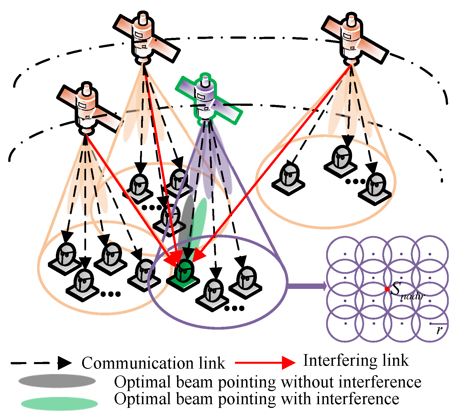
In this paper, we consider the dense LEO satellite communication system composed of many LEO satellites with different orbital planes, which leads to overlapped coverage areas. Both satellites and UTs are equipped with uniform rectangular arrays (URAs). Every satellite can generate several fixed pointing circular beams to provide service for ground users, as shown in Figure 1. These satellite beams move with the motion of the satellite. The UTs are generated randomly, and each UT has one flexible circular beam to realize beam alignment. Thus, the existence time of the overlapping coverage area for fixed-position UTs is limited; moreover, the full frequency reuse is considered among all satellites. Generally, the satellite ephemeris broadcasted periodically can be utilized to obtain the satellite location. The time-varying beam center position can also be obtained via its relative position to the location of the nadir of the satellite, as shown in Figure 1.
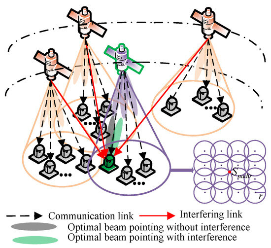
Figure 1.
The dense LEO satellite communication system.
2.2. Antenna Model
In this paper, planar URA is employed for the satellite and the UT. According to 3GPP TR 37.840 [22], the LEO satellite and UT antenna pattern can be derived. The composite array radiation pattern of the satellite is expressed as follows:
where is the satellite antenna gain at the transmitter, which is composed of single element gain and array gain , and are the elevation and azimuth angle of AoD, and denote the electrical down-tilt steering and the electrical horizontal steering, which represent the beam center pointing of the satellite antenna.
Similarly, the antenna model of the UT is as follows:
where is the UT antenna receiving gain, and are the elevation and azimuth angle of AoA, and express the electrical down-tilt steering and the electrical horizontal steering, which denote the beam center pointing of UT antenna.
2.3. Signal Model
As shown in Figure 1, when multiple satellites share the same frequency bands, the UT will receive communication and interfering signals simultaneously. Moreover, satellite-to-ground communication undergoes several stages of propagation and attenuation. Free space path loss, atmospheric absorption, and rain attenuation are mainly considered in path loss (PL). Then, PL can be given as follows:
where is the free space path loss [23], is the atmospheric absorption [23]. Specifically, is the distance between the satellite and the UT, is the carrier frequency, is the zenith attenuation, and is the elevation angle. Moreover, rain attenuation is the most dominant cause of signal degradation for the Ka-band, and it can be represented as follows: [24], in which is the predicted attenuation exceeded for of an average year, p is the exceedance probability, is the elevation angle, and is given as follows:
and is the latitude of the UT. The above rain attenuation model has been used in the existing research [25,26]. Moreover, the effect of rain attenuation during radio propagation and the new rain attenuation model have been studied in [27,28,29,30,31]; however, this is not the focus of this paper.
The received signal strength is given as follows:
where the subscripts t and r denote the transmitter and receiver. is the set of visible satellites, which is composed of the serving satellite S and the interfering satellites I. denotes the satellite antenna transmit power. and are the antenna transmitting and receiving gain according to (1) and (2). Moreover, the received signal strength of serving signal and interfering signal are obtained by (5), and can be represented as and .
Thus, the SINR at the receiver is written as follows:
where , Q is the total number of interfering satellites at the time index n, D is the total number of interfering links generated by an interfering satellite, which is equal to the number of beams that use the same frequency bands. denotes the dth interfering link of the qth interfering satellite. K is the Boltzmann’s constant and, given as dBW/K/Hz, T represents the noise temperature, and means the bandwidth of the LEO satellite communication system.
2.4. Problem Formulation
In Figure 1, the beam, colored black, points directly to its serving satellite without considering the co-channel interference generated by other satellites. Actually, the beam pointing of the UT antenna needs to be shifted to other directions for interference mitigation, represented as the green beam in Figure 1. Moreover, interference avoidance for the time-varying dense LEO networks is challenging.
To solve the time-varying interference problem, we will decompose the continuous time-varying interference situation into multiple discrete time slots. Then, we intend to maximize the SINR of the communication link at the receiver to obtain the optimal beam pointing of the receiving antenna at every moment, and the problem is formulated as follows:
where and are the horizontal and vertical 3 dB beamwidth of the main beam of the UT antenna, and are the elevation and azimuth angles of AoA of the communication link. (7a) and (7b) represent the range of the UT antenna beam center adjustment. The above constraints can help to reduce the beam search space.
3. Interference Situational Aware Beam Pointing Optimization
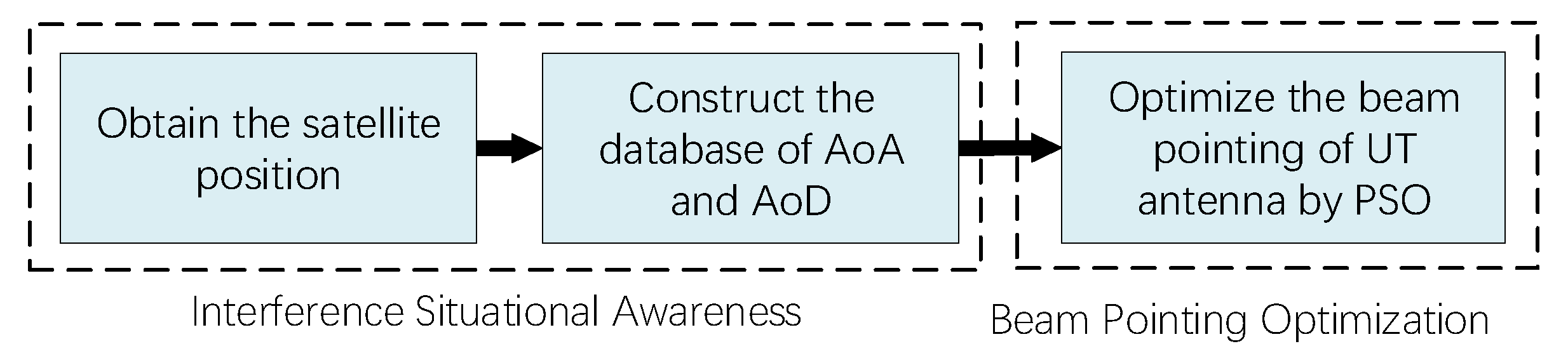
The beam pointing optimization problem in (7) is a non-convex optimization problem, and the non-convexity is introduced by SINR in (6) [32]. Generally, the non-convex problem is challenging to be solved directly. However, as a heuristic optimization method, PSO can solve convex and non-convex optimization problems by finding the optimal solution in the search space through a collaborative particle swarm optimization and a fitness function [33]. In this section, the scheme of an interference situational aware beam pointing optimization is introduced, as shown in Figure 2. Firstly, the satellite position data are obtained. Based on the coordinate system conversion, the database of AoD and AoA is constructed. Then, the database can be utilized for PSO to optimize the beam center pointing of the UT antenna by maximizing the SINR.
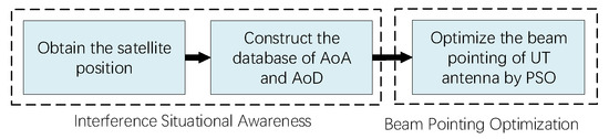
Figure 2.
The scheme of interference situational aware beam pointing optimization.
3.1. Interference Situational Awareness
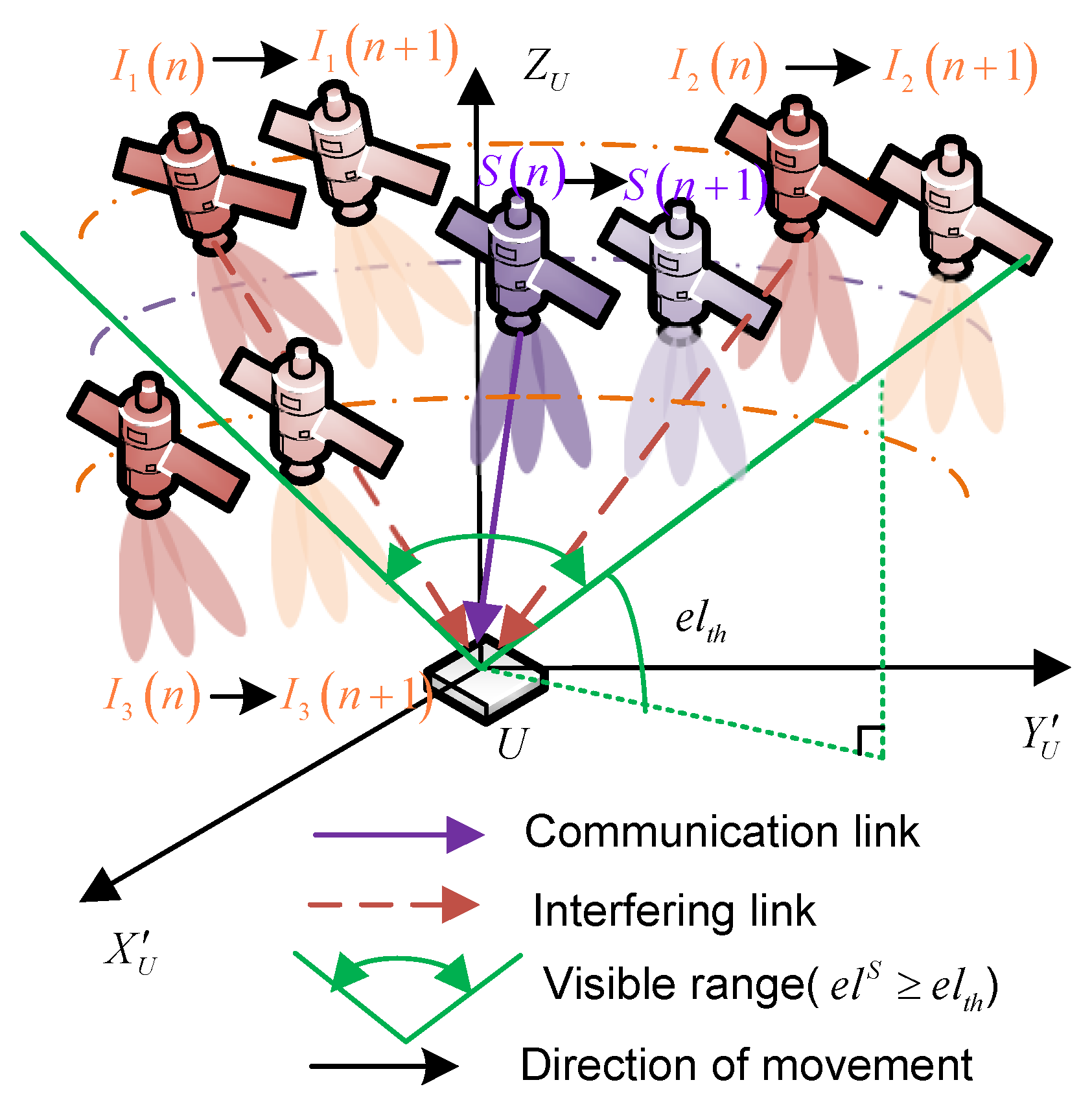
For a given UT, the visible satellites change dynamically, as shown in Figure 3. Thus, the visible satellite set is as follows:
where the elevation angle of satellite observed by UT can be calculated using the location of satellite and UT, is the minimum visibility elevation angle.

Figure 3.
The variation in visible satellites.
According to the visible satellite set , the serving satellite S is selected based on the maximum remaining service time, while the other satellites are interfering satellites I. Due to satellite movement, the interfering satellites observed by the UT are time-varying. The time-varying interfering satellite set at the time index n is expressed as , where Q is the total number of interfering satellites and varies with time.
To obtain the AoA and AoD of communication and interfering links, coordinate conversion is implemented. Firstly, local coordinate systems (LCSs) of the satellite and UT are defined. Then, the location information of the satellite and UTs in the global coordinate system (GCS) represented by the Earth-centered Earth-fixed (ECEF) coordinate system should be converted to the LCS for each satellite and UT. The detailed conversion steps are provided in 3GPP TR 38.901 [34].
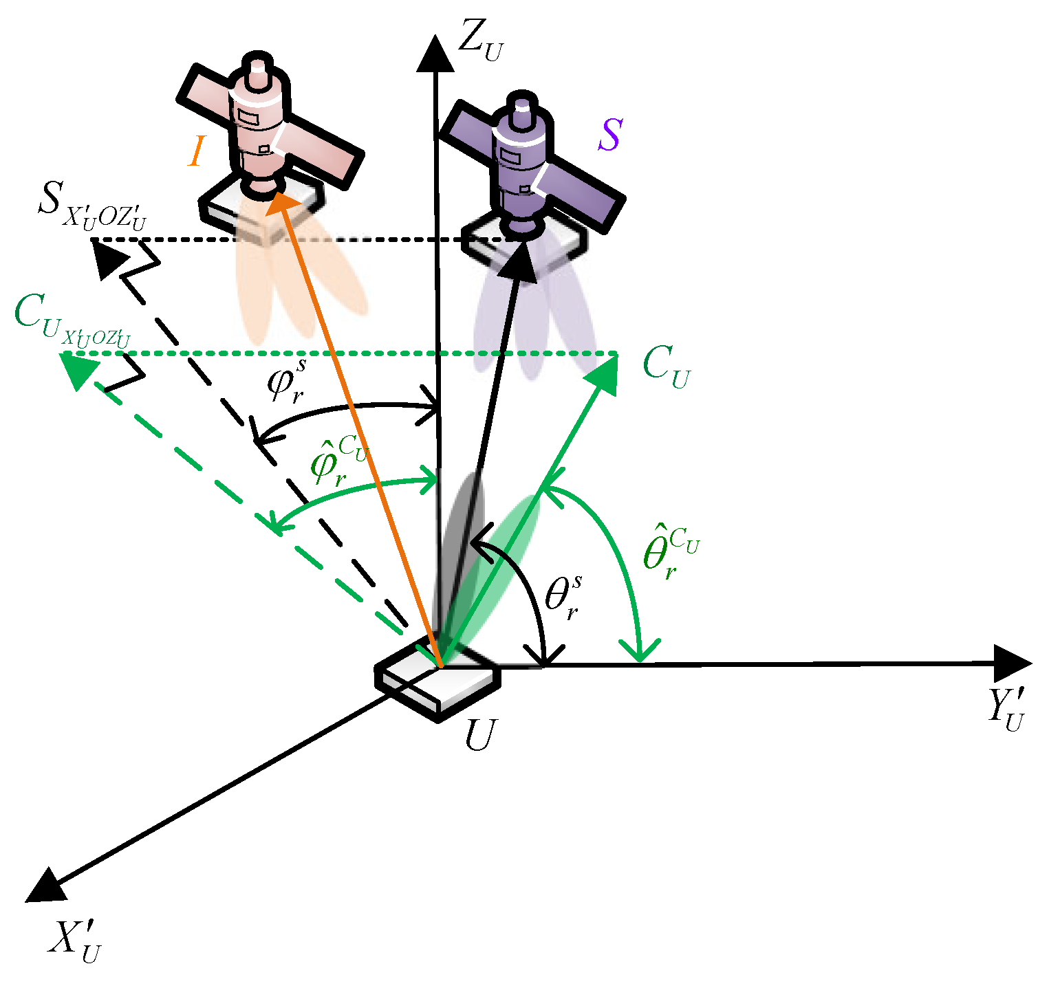
As shown in Figure 4, S, I, and U denote the serving satellite, interfering satellite, and UT. is the GCS, is the local coordinate system of serving satellite (LCS−S), is the local coordinate system of interfering satellite (LCS−I), and denotes the local coordinate system of the UT (LCS−U). Additionally, and denote the beam center of the serving and interfering satellite, respectively. is the beam center of the UT antenna.
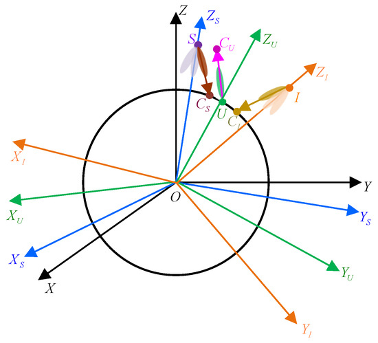
Figure 4.
The GCS and LCS coordinate systems.
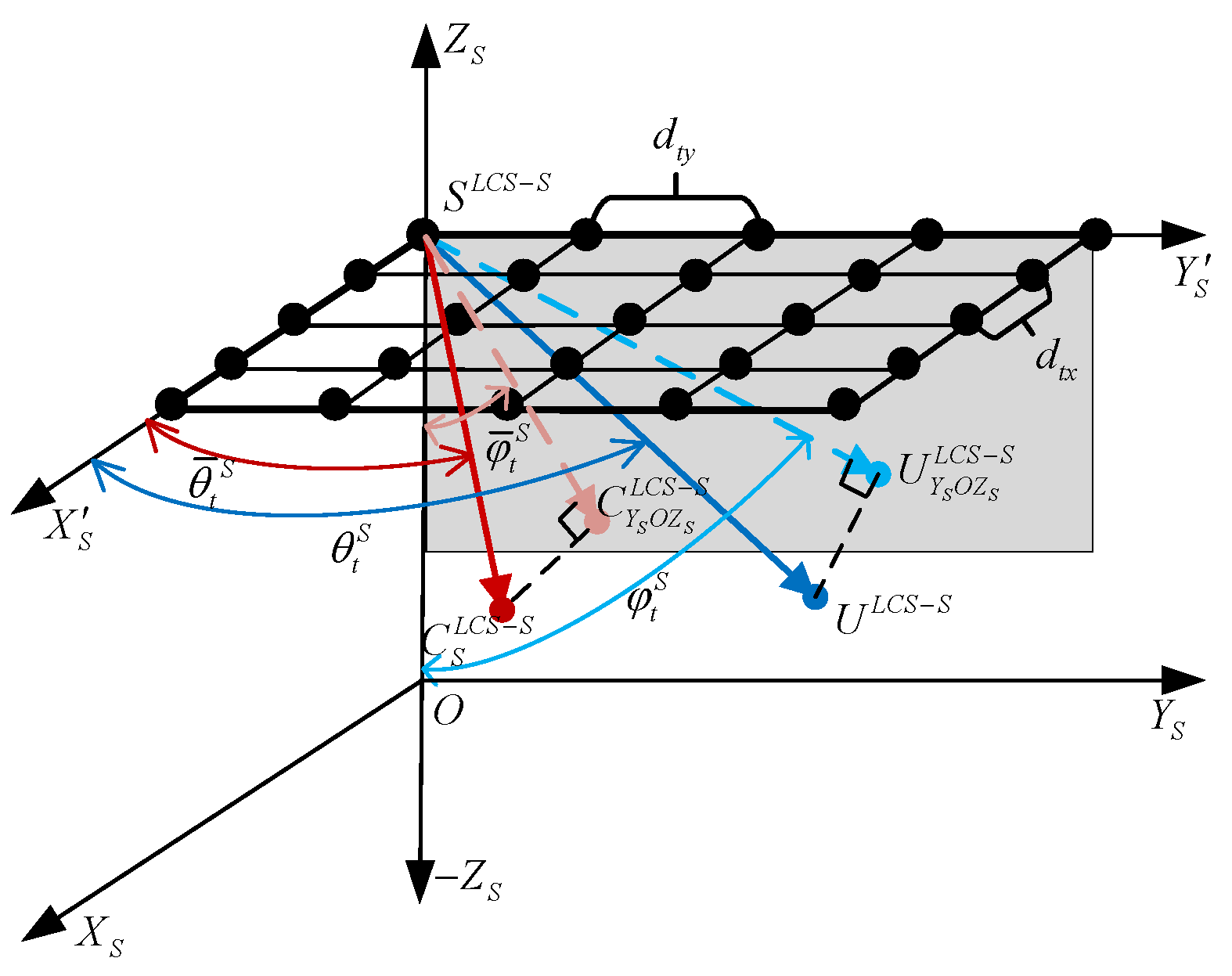
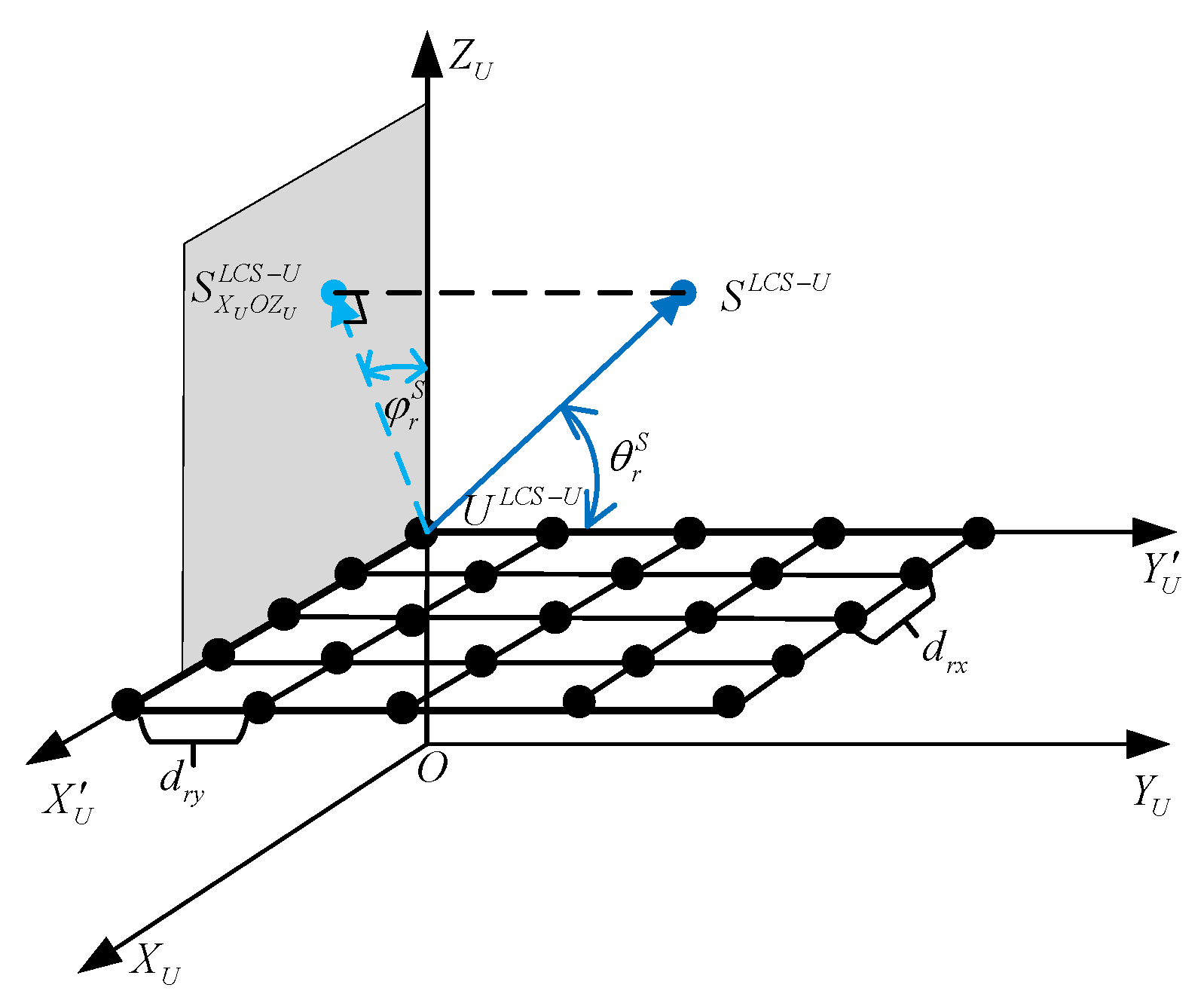
Figure 5 and Figure 6 show the serving satellite and UT antenna placed in LCS−S and LCS−U, respectively. The total number of antenna elements of the satellite and UT are and . and are the number of antenna elements along x-axis and y-axis at the transmitter, while and are the numbers of antenna elements along x-axis and y-axis at the receiver. , , , and are the distance between adjacent antenna elements along x-axis and y-axis at the transmitting and receiving antenna. and are defined as the azimuth and elevation angle of AoD of the communication link, while and are the azimuth and elevation angle of AoA of the communication link.
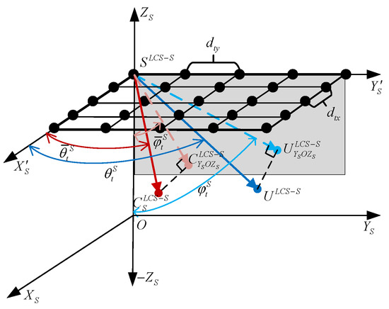
Figure 5.
The serving satellite antenna placed in LCS-S.

Figure 6.
The UT antenna placed in LCS-U.
The elevation and azimuth angles of AoD and AoA of the communication link can be estimated by the following:
where and are parallel to and in the LCS-S. and are parallel to and in the LCS-U. x-axis, y-axis, and z-axis can be represented by the three unit vectors , , and . Moreover, is the projection of the UT U onto the -plane in the LCS-S. is the projection of satellite S onto the -plane in the LCS-U.
Moreover, the beam center pointing of the satellite antenna is given by the following:
Similarly, we can replace the serving satellite in the above derivation with interfering satellites. Thus, the AoD and AoA of the interfering links can also be estimated. Then, the interference situational aware database can be constructed, and the time-varying interference can be obtained as follows:
where ,.
3.2. Beam Pointing Optimization
Traditionally, the beam center of the UT antenna should point to the communication link AoA. As shown in Figure 7, the beam colored as black points to its serving satellite with ). However, co-channel interference occurs inevitably due to the same frequency reuse among satellites. Therefore, the beam center pointing of the UT needs to be optimized for interference mitigation. In Figure 7, the green beam direction denotes the optimized beam center pointing of the UT antenna (i.e., ).
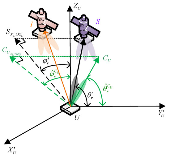
Figure 7.
Beam pointing optimization under interference.
During the service time of the serving satellite, the interfering satellites vary dynamically. To characterize the time-varying interference and communication links, the AoA and AoD of interfering and communication links have been divided into discrete status for each time slot in Section 3.1. Thus, the interference is fixed for each time slot. We intend to use the PSO algorithm to maximize the SINR at each time slot to obtain the corresponding optimal beam center pointing.
We take the beam pointing optimization process at time index n as an example. The interference situation at the single time slot can be obtained via (15) and (16). Then, the PSO optimization method can be adopted to achieve the optimal beam pointing of each UT. The advantage and detailed description of the PSO algorithm can be found in [33,35,36]. In this paper, we explain how to implement the PSO algorithm to solve the problem defined in (7). Let the number of the particle swarm of PSO optimization be J, and the maximum iteration is M. The upper and lower bounds of the particle swarm two-dimensional search space are defined as follows: , , , and , where and are the communication link AoA estimated by (11) and (12), and are the horizontal and vertical 3 dB beamwidth of the UT antenna.
Specifically, the position and velocity of the jth particle are represented as follows:
where denotes the mth iteration at the time index n, , and . Particle position represents the elevation and azimuth angles of beam center pointing of the UT, and are restricted in and , denotes the particle velocity and is limited between and .
The fitness function is as follows:
Based on the fitness function, the individual and group position optimal value of the particle swarm at the mth iteration are expressed as follows: and . Then, with the guidance of and , the velocity and position of the jth particle at th iteration can be updated by the following:
where and are learning factors, and and are random numbers in to increase search randomness. The inertia weight will affect the performance and convergence speed of the algorithm [36]. In this paper, the linear inertia factor is adopted as follows [33]:
where and are the upper and lower bounds of the inertia weight.
The above process will be repeated at the time index n until the maximum iteration M is reached. The corresponding optimized result . Thus, the optimal result of the whole observation time N can be obtained by applying the above optimization process at each time slot, and it can be expressed as follows: . The detailed process for the PSO optimization process can be found in Algorithm 1.
| Algorithm 1 Beam pointing optimization based on PSO |
|
4. Results
In this section, we consider the dense LEO satellite communication scenario consisting of 6372 satellites in the Ka-band and multiple UTs. The orbital parameters of the LEO constellation are listed in Table 2 [37]. The positions of multiple users are randomly generated in a selected ground area, and the number of users is 16. Moreover, the detailed simulation parameters are shown in Table 3. Note that the peak gain and 3 dB beamwidth of the satellite antenna in Table 3 are applied for a single beam. The simulation environment is built on a PC with an Intel Core i7-10700F, 16 GB of RAM, and a Windows 10 (64 bit) system. In this paper, the data of satellite position are exported from Satellite Tool Kit (STK) 11.2.0, which provides a physics-based modeling environment for analyzing platforms and payloads in a realistic mission context [38]. Due to the movement of the satellites, the overlapping area appears first and then disappears. Thus, the entire time of users covered by the overlapping coverage area is limited, and the maximum duration time is 21 s. During the entire simulation time, the maximum number of interfering satellites is , and the minimum time slot is 1 s [19].
Table 2.
Orbital parameters [37].
Table 3.
Simulation parameters.
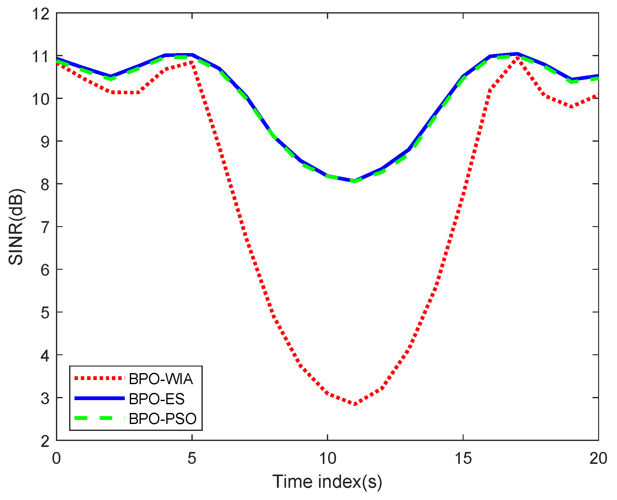
We take the exhaustive search (ES) as the reference to verify the effectiveness of beam pointing optimization based on PSO. The ES traverses all directions with and finds the maximum SINR. The PSO algorithm is implemented on each UT and runs independently. To compare the performance of difference schemes clearly, we select a user located at (39.56° N, 116.20° E) to show the simulations in Figure 8, Figure 9 and Figure 10. For clarity, the scheme without a beam pointing optimization for interference avoidance is defined as BPO-WIA, while the schemes with a beam pointing optimization using ES and PSO are denoted as BPO-ES and BPO-PSO, respectively.
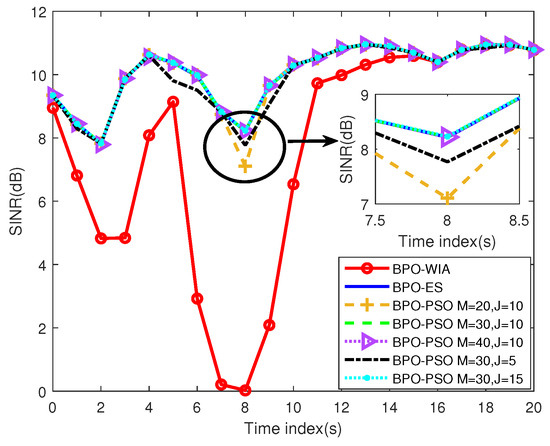
Figure 8.
The variation in SINR over time.
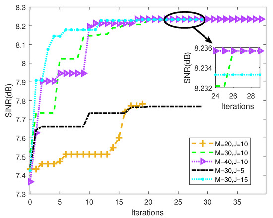
Figure 9.
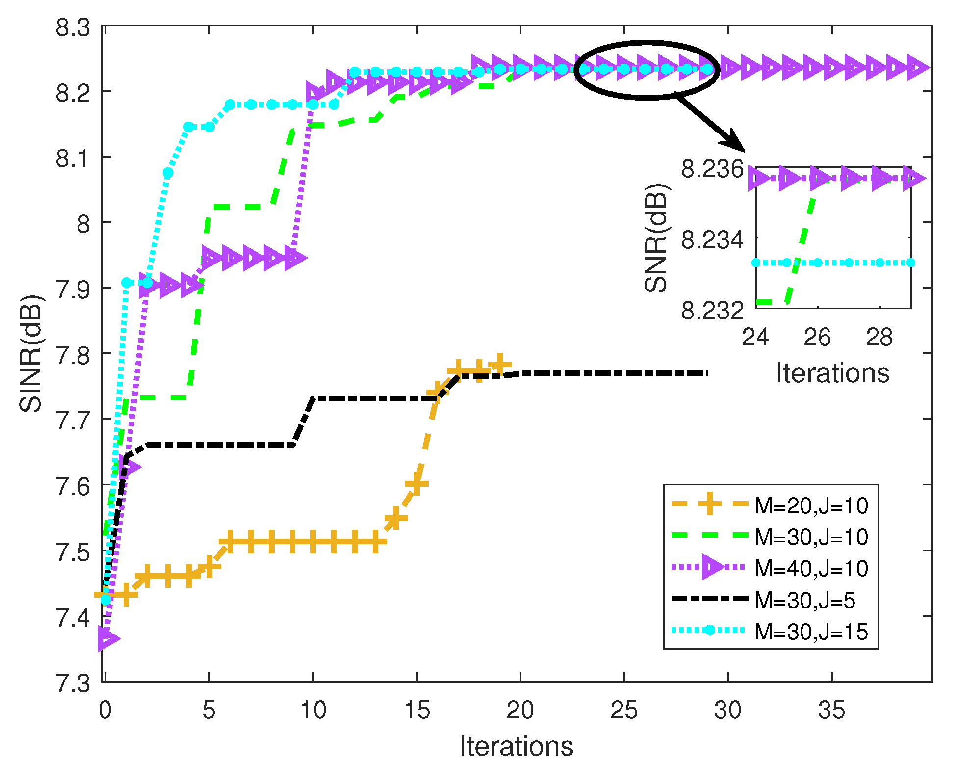
The convergence curve of BPO-PSO for time index .
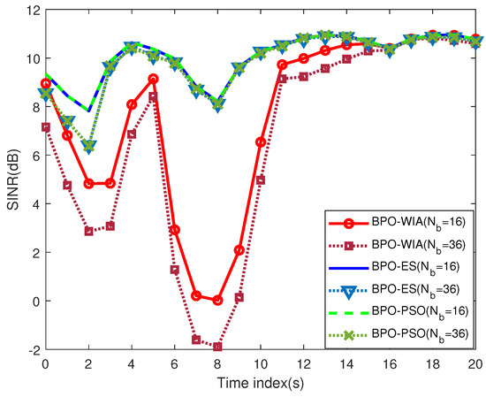
Figure 10.
The SINR with different number of beams.
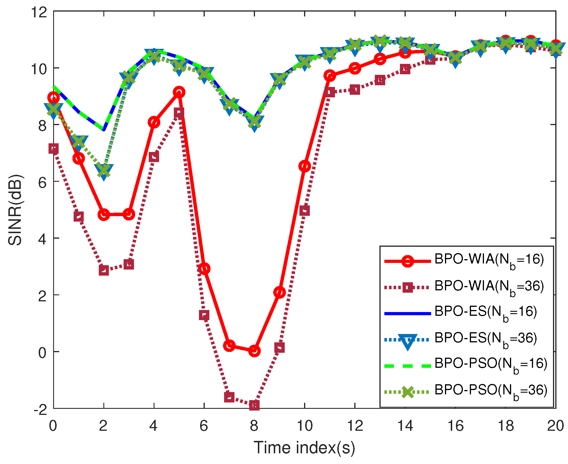
In Figure 8, the SINR using BPO-WIA initially decreases and then increases. This is because the motion of the satellites causes the overlapping area to first increase and then decrease. Thus, the interference also increases first and then decreases. The most severe interference occurs when the user is covered by the center of the maximum beam overlapping area, so the SINR is low and even close to 0 dB at time index and . The lowest and average SINR is dB (time index ) and dB, respectively. The SINR with BPO-ES has the optimal SINR performance. However, the computation complexity of BPO-ES is highest, i.e., , where is 0.1°. The time consumption for BPO-ES at each time slot is s, as shown in Table 4.
Table 4.
Complexity comparison.
In Figure 8, the optimized SINR of different particles and maximum iterations are shown. Moreover, the corresponding convergence curve at the moment of the strongest interference (time index ) is depicted in Figure 9. In Figure 8 and Figure 9, when the number of particles is set as , the obtained SINR using or outperforms that using . In addition, when the maximum iterations are set to , the optimized SINR using or is better than that using . It can be concluded that the optimal value can be found with proper iterative times or particles. Furthermore, the time consumption is related to the number of particles and iterations. As shown in Table 4, the computation complexity of BPO-PSO is . To balance optimization performance and time consumption, we choose and in this paper. Its runtime for the one-shot optimization is approximately s. According to Figure 8, BPO-PSO and BPO-ES can achieve almost the same performance and are better than BPO-WIA during the simulation time. The SINR achieved by BP-ES and BP-PSO at the strongest interference moment is dB (time index ), and the average SINR is dB. Thus, BPO-PSO is more suitable for the high dynamic LEO satellite scenario than BPO-ES due to its lower time consumption.
The SINR with different numbers of beams is shown in Figure 10. The original SINR with BPO-WIA using is lower than due to the influence of co-channel interference. This is because the total beam coverage area and interfering links are increased due to the increase in the number of beams, which leads to a higher interference level. Moreover, at the time index , the improvement of SINR obtained by BPO-PSO with and is dB and dB, respectively. At time index , the improvement of SINR obtained by BPO-PSO with and is dB and dB, respectively. Thus, the BPO-PSO proposed in this paper can improve SINR with more gains for stronger interference scenarios, and it can also be applied to scenarios with various numbers of beams.
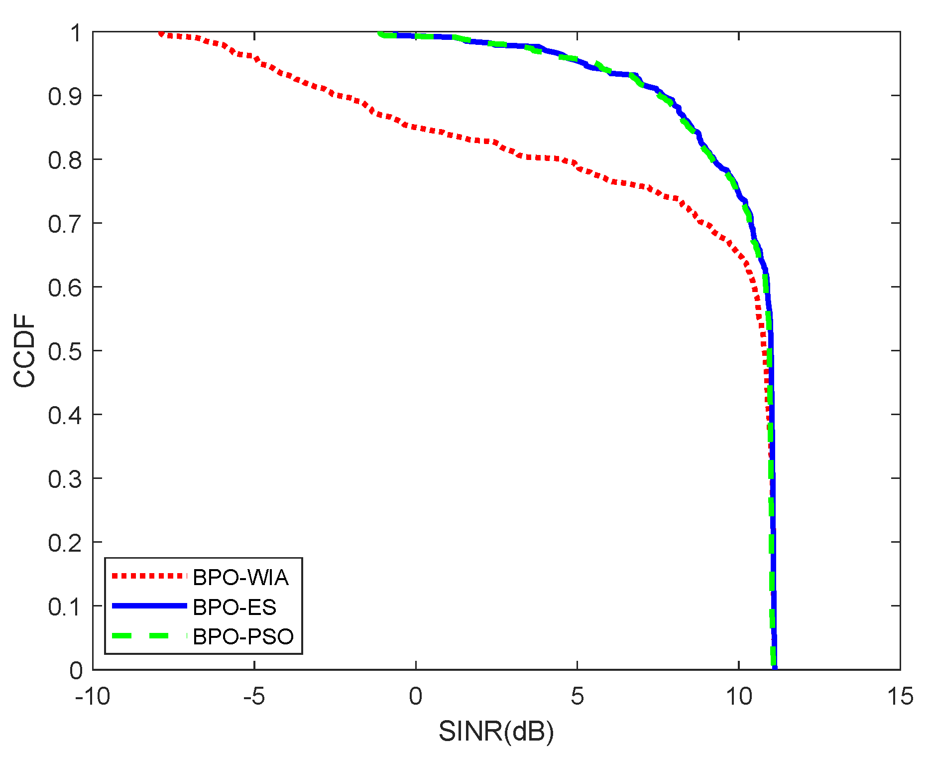
Furthermore, the simulation results of the multi-user scenario are provided in Figure 11, Figure 12 and Figure 13. The receiving antenna pointing of each user can be optimized separately and achieve the maximum SINR. Based on the above optimized SINR, the complementary cumulative distribution function (CCDF) of the SINR is depicted in Figure 11. The minimum SINR of BPO-WIA is dB, while the minimum SINR of BPO-ES and BPO-PSO is dB and dB. Compared to BPO-WIA, the probability of BPO-PSO can achieve % and % improvement at SINR dB and 10 dB; thus, the SINR is effectively improved for stronger interference. The multi-user average SINR of BPO-WIA, BPO-ES, and BPO-PSO is depicted in Figure 12. The maximum, minimum, and mean SINR of multi-user with BPO-WIA are dB, dB, and dB. With BPO-ES, the maximum, minimum, and mean SINR of multi-user are dB, dB, and dB. With BPO-PSO, the maximum, minimum, and mean SINR of multi-user are dB, dB, and dB. The average SINR of BPO-PSO is enhanced by % compared to BPO-WIA. Moreover, compared to BPO-ES, the relative error of mean SINR of multi-user obtained by BPO-PSO is %. Furthermore, the equivalent power flux density (EPFD) proposed in ITU Radio Regulations is used to evaluate the interference mitigation performance [40]; the higher EPFD means a higher interference. The cumulative distribution function (CDF) curves of EPFD are given in Figure 13. It can be seen that the CDF curve of EPFD of BPO-PSO basically overlaps with that of BPO-ES. Furthermore, the EPFD performance of BPO-ES and BPO-PSO is better than that of BPO-WIA. For example, the probability of BPO-PSO is improved by % compared to BPO-WIA for EPFD = 103 dBW/m2.
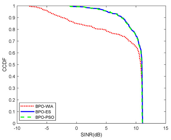
Figure 11.
The CCDF of SINR.
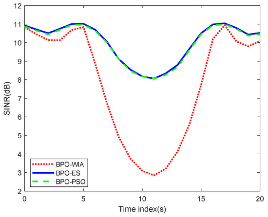
Figure 12.
The average SINR comparison of BPO-WIA, BPO-ES, and BPO-PSO.
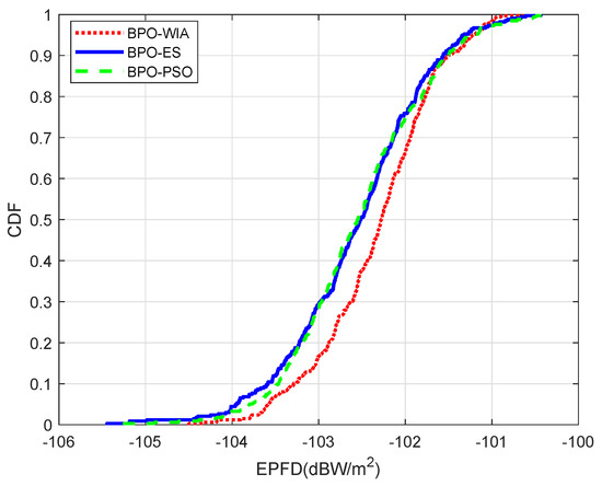
Figure 13.
The CDF of EPFD.
5. Conclusions
We mainly study the interference avoidance techniques for dense LEO satellite systems by optimizing the user antenna beam pointing. In this paper, the beam pointing optimization is modeled as a non-convex optimization problem. To solve the problem, the interference situational aware database composed of AoD and AoA of interfering satellites can be constructed and used for a distributed PSO-based beam pointing optimization. Then, the optimal beam pointing of the UT antenna can be obtained by maximizing the received SINR of each UT. Simulation results show that the relative error of the mean SINR obtained by BPO-PSO is %. So, the proposed method can effectively mitigate the co-channel interference by adjusting the beam pointing of the UT antennas.
Author Contributions
Conceptualization, M.H. and G.C.; software, M.H.; validation, M.H.; formal analysis, M.H., G.C., W.W., X.C. and L.X.; investigation, M.H. and G.C.; data curation, M.H.; writing—original draft preparation, M.H.; writing—review and editing, M.H., G.C., W.W., X.C. and L.X.; visualization, M.H.; supervision, G.C., W.W., X.C. and L.X.; project administration, M.H.; funding acquisition, G.C. and W.W. All authors have read and agreed to the published version of the manuscript.
Funding
This research was funded by the National Natural Science Foundation of China grant number 62171052 and the Fundamental Research Funds for the Central Universities with the number of No. 24820232023YQTD01.
Institutional Review Board Statement
Not applicable.
Informed Consent Statement
Not applicable.
Data Availability Statement
The data that support the findings of this study are available from the corresponding author upon reasonable request.
Conflicts of Interest
Author Xinzhou Cheng and Lexi Xu were employed by the company China United Network Communications Corporation. The remaining authors declare that the research was conducted in the absence of any commercial or financial relationships that could be construed as a potential conflict of interest.
Abbreviations
The following abbreviations are used in this manuscript:
| LEO | Low earth orbit |
| AoD | Angle of departure |
| AoA | Angle of arrival |
| PSO | Particle swarm optimization |
| UT | User terminal |
| SINR | Signal-to-interference plus noise ratio |
| GEO | Geostationary earth orbit |
| NGEO | Non-geostationary earth orbit |
| SI | Spatial isolation |
| CR | Cognitive radio |
| APC | Adaptive power control |
| BH | Beam hopping |
| BPO | Beam pointing optimization |
| URAs | Uniform rectangular arrays |
| PL | Path loss |
| LCS | Local coordinate system |
| GCS | Global coordinate system |
| ECEF | Earth-centered Earth-fixed |
| LCS-S | Local coordinate system of serving satellite |
| LCS-I | Local coordinate system of interfering satellite |
| LCS-U | Local coordinate system of the UT |
| STK | Satellite Tool Kit |
| ES | Exhaustive search |
| BPO-WIA | Without beam pointing optimization for interference avoidance |
| BPO-ES | Beam pointing optimization using ES |
| BPO-PSO | Beam pointing optimization using PSO |
| CCDF | Complementary cumulative distribution function |
| EPFD | Equivalent power flux density |
| CDF | Cumulative distribution function |
References
- Wang, T.; Li, W.; Li, Y. Co-Frequency interference analysis between large-scale NGSO constellations and GSO systems. In Proceedings of the 12th International Conference on Wireless Communications and Signal Processing (WCSP), Nanjing, China, 21–23 October 2020; pp. 679–684. [Google Scholar] [CrossRef]
- Neinavaie, M.; Khalife, J.; Kassas, Z.M. Acquisition, Doppler tracking, and positioning with Starlink LEO satellites: First results. IEEE Trans. Aerosp. Electron. Syst. 2022, 58, 2606–2610. [Google Scholar] [CrossRef]
- Del Portillo, I.; Cameron, B.G.; Crawley, E.F. A technical comparison of three low earth orbit satellite constellation systems to provide global broadband. Acta Astronaut. 2019, 159, 123–135. [Google Scholar] [CrossRef]
- Zhang, H. Spatial isolation methodology analysis in Ka band for LEO-GEO coexistence systems. In Proceedings of the 2018 International Conference on Robots & Intelligent System (ICRIS), Changsha, China, 26–27 May 2018; pp. 291–295. [Google Scholar] [CrossRef]
- Al-Hraishawi, H.; Chougrani, H.; Kisseleff, S.; Lagunas, E.; Chatzinotas, S. A survey on nongeostationary satellite systems: The communication perspective. IEEE Commun. Surv. Tutor. 2023, 25, 101–132. [Google Scholar] [CrossRef]
- Huangt, W.; Liu, Y.; Wang, W.; Geng, J. A GSO protected area calculation model based on controllable NGSO system parameters. In Proceedings of the 2021 IEEE Symposium on Computers and Communications (ISCC), Athens, Greece, 5–8 September 2021; pp. 1–6. [Google Scholar] [CrossRef]
- Zhang, C.; Jiang, C.; Kuang, L.; Jin, J.; He, Y.; Han, Z. Spatial spectrum sharing for satellite and terrestrial communication networks. IEEE Trans. Aerosp. Electron. Syst. 2019, 55, 1075–1089. [Google Scholar] [CrossRef]
- Yin, L.; Yang, R.; Yang, Y.; Deng, L.; Li, S. Beam pointing optimization based downlink interference mitigation technique between NGSO satellite systems. IEEE Wirel. Commun. Lett. 2021, 10, 2388–2392. [Google Scholar] [CrossRef]
- Pandian, P.; Selvaraj, C.; Bhalaji, N.; Arun Depak, K.G.; Saikrishnan, S. Machine learning based spectrum prediction in cognitive radio networks. In Proceedings of the 2023 International Conference on Networking and Communications (ICNWC), Chennai, India, 5–6 April 2023; pp. 1–6. [Google Scholar] [CrossRef]
- Rapetswa, K.; Cheng, L. Towards a multi-agent reinforcement learning approach for joint sensing and sharing in cognitive radio networks. Intell. Converg. Netw. 2023, 4, 50–75. [Google Scholar] [CrossRef]
- Somula, L.R.; Meena, M. K-nearest neighbour (KNN) algorithm based cooperative spectrum sensing in cognitive radio networks. In Proceedings of the 4th International Conference on Cybernetics, Cognition and Machine Learning Applications (ICCCMLA), Goa, India, 8–9 October 2022; pp. 1–6. [Google Scholar] [CrossRef]
- Gu, P.; Li, R.; Hua, C.; Tafazolli, R. Dynamic cooperative spectrum sharing in a multi-beam LEO-GEO co-existing satellite system. IEEE Trans. Wirel. Commun. 2022, 21, 1170–1182. [Google Scholar] [CrossRef]
- Zhang, C.; Jiang, C.; Jin, J.; Wu, S.; Kuang, L.; Guo, S. Spectrum sensing and recognition in satellite systems. IEEE Trans. Veh. Technol. 2019, 68, 2502–2516. [Google Scholar] [CrossRef]
- Wang, Y.; Ding, X.; Zhang, G. A novel dynamic spectrum-sharing method for GEO and LEO satellite networks. IEEE Access 2020, 8, 147895–147906. [Google Scholar] [CrossRef]
- Sharma, S.K.; Chatzinotas, S.; Ottersten, B. In-line interference mitigation techniques for spectral coexistence of GEO and NGEO satellites. Int. J. Satell. Commun. Netw. 2016, 34, 11–39. [Google Scholar] [CrossRef]
- Li, R.; Gu, P.; Hua, C. Optimal beam power control for co-existing multibeam GEO and LEO satellite system. In Proceedings of the 2019 11th International Conference on Wireless Communications and Signal Processing (WCSP), Xi’an, China, 23–25 October 2019; pp. 1–6. [Google Scholar] [CrossRef]
- Lin, Z.; Ni, Z.; Kuang, L.; Jiang, C.; Huang, Z. NGSO satellites beam hopping strategy based on load balancing and interference avoidance for coexistence with GSO systems. IEEE Commun. Lett. 2023, 27, 278–282. [Google Scholar] [CrossRef]
- Lin, Z.; Ni, Z.; Kuang, L.; Jiang, C.; Huang, Z. Multi-satellite beam hopping based on load balancing and interference avoidance for NGSO satellite communication systems. IEEE Trans. Commun. 2023, 71, 282–295. [Google Scholar] [CrossRef]
- Zhang, C.; Jin, J.; Zhang, H.; Li, T. Spectral coexistence between LEO and GEO satellites by optimizing direction normal of phased array antennas. China Commun. 2018, 15, 18–27. [Google Scholar] [CrossRef]
- Su, Y.; Liu, Y.; Zhou, Y.; Yuan, J.; Cao, H.; Shi, J. Broadband LEO satellite communications: Architectures and key technologies. IEEE Wirel. Commun. 2019, 26, 55–61. [Google Scholar] [CrossRef]
- Matricciani, E. Geocentric spherical surfaces emulating the geostationary orbit at any latitude with zenith links. Future Internet 2020, 12, 16. [Google Scholar] [CrossRef]
- 3GPP. Study of Radio Frequency (RF) and Electromagnetic Compatibility (EMC) Requirements for Active Antenna Array System (AAS) Base Station (Release 12). Technical Report (TR) 37.840, 3rd Generation Partnership Project (3GPP), Version 12.1.0. 2013. Available online: https://portal.3gpp.org/desktopmodules/Specifications/SpecificationDetails.aspx?specificationId=2624 (accessed on 1 June 2022).
- 3GPP. Study on New Radio (NR) to Support Non-Terrestrial Networks (Release 15). Technical Report (TR) 38.811, 3rd Generation Partnership Project (3GPP). Version 15.14.0. 2020. Available online: https://www.3gpp.org/dynareport?code=38-series.htm&device=desktop (accessed on 2 October 2020).
- Propagation Data and Prediction Methods Required for the Design of Earth-Space Telecommunication Systems; ITU-R P.618-13 Technical Report; International Telecommunication Union: Geneva, Switzerland, 2017.
- Lu, C.S.; Zhao, Z.W.; Wu, Z.S.; Lin, L.K.; Thiennviboon, P.; Zhang, X.; Lv, Z.F. A new rain attenuation prediction model for the earth-space links. IEEE Trans. Antennas Propag. 2018, 66, 5432–5442. [Google Scholar] [CrossRef]
- Momin, M.; Alam, M.M.; Hasan Mahfuz, M.M.; Islam, M.R.; Hadi Habaebi, M.; Badron, K. Prediction of rain attenuation on earth-to-satellite link using rain rate measurement with various integration times. In Proceedings of the 2021 8th International Conference on Computer and Communication Engineering (ICCCE), Kuala Lumpur, Malaysia, 22–23 June 2021; pp. 385–390. [Google Scholar] [CrossRef]
- Capsoni, C.; Matricciani, E.; Mauri, M. SIRIO-OTS 12 GHz orbital diversity experiment at Fucino. IEEE Trans. Antennas Propag. 1990, 38, 777–782. [Google Scholar] [CrossRef]
- Matricciani, E.; Mauri, M. Italsat-Olympus 20-GHz orbital diversity experiment at Spino d’Adda. IEEE Trans. Antennas Propag. 1995, 43, 105–108. [Google Scholar] [CrossRef]
- Matricciani, E. Prediction of orbital diversity performance in satellite communication systems affected by rain attenuation. Int. J. Satell. Commun. 1997, 15, 45–50. [Google Scholar] [CrossRef]
- Mohd Zain, A.F.; Albendag, A.A.M. Improving ITU-R rain attenuation model for HAPS earth-space link. In Proceedings of the 2013 IEEE International Conference on Space Science and Communication (IconSpace), Melaka, Malaysia, 1–3 July 2013; pp. 56–59. [Google Scholar] [CrossRef]
- Kourogiorgas, C.; Panagopoulos, A.D. A rain-attenuation stochastic dynamic model for LEO satellite systems above 10 GHz. IEEE Trans. Vehi. Technol. 2015, 64, 829–834. [Google Scholar] [CrossRef]
- Lin, Z.; Ni, Z.; Kuang, L.; Jiang, C.; Huang, Z. Dynamic beam pattern and bandwidth allocation based on multi-agent deep reinforcement learning for beam hopping satellite systems. IEEE Trans. Veh. Technol. 2022, 71, 3917–3930. [Google Scholar] [CrossRef]
- Shami, T.M.; El-Saleh, A.A.; Alswaitti, M.; Al-Tashi, Q.; Summakieh, M.A.; Mirjalili, S. Particle swarm optimization: A comprehensive survey. IEEE Access 2022, 10, 10031–10061. [Google Scholar] [CrossRef]
- 3GPP. Study on Channel Model for Frequencies from 0.5 to 100 GHz (Release 17). Technical Report (TR) 38.901, 3rd Generation Partnership Project (3GPP). Version 17.0.0. 2022. Available online: https://portal.3gpp.org/desktopmodules/Specifications/SpecificationDetails.aspx?specificationId=3173 (accessed on 19 March 2022).
- Mathebula, T.; Chowdhury, S. Optimal placement of distributed energy resources using particle swarm optimization techniques: A review. In Proceedings of the 2020 IEEE PES/IAS PowerAfrica, Nairobi, Kenya, 25–28 August 2020; pp. 1–5. [Google Scholar] [CrossRef]
- Duan, Y.; Chen, N.; Chang, L.; Ni, Y.; Kumar, S.V.N.S.; Zhang, P. CAPSO: Chaos adaptive particle swarm optimization algorithm. IEEE Access 2022, 10, 29393–29405. [Google Scholar] [CrossRef]
- Pachler, N.; del Portillo, I.; Crawley, E.F.; Cameron, B.G. An updated comparison of four low earth orbit satellite constellation systems to provide global broadband. In Proceedings of the 2021 IEEE International Conference on Communications Workshops (ICC Workshops), Montreal, QC, Canada, 14–23 June 2021; pp. 1–7. [Google Scholar] [CrossRef]
- Available online: https://www.ansys.com/products/missions/ansys-stk (accessed on 21 March 2021).
- 3GPP. Study on Solutions for NR to Support Non-Terrestrial Networks (Release 16). Technical Report (TR) 38.821, 3rd Generation Partnership Project (3GPP). Version 16.2.0. 2023. Available online: https://portal.3gpp.org/desktopmodules/Specifications/SpecificationDetails.aspx?specificationId=3525 (accessed on 1 April 2023).
- ITU. Radio Regulations; Technical Report, R-REG-RR; International Telecommunication Union: Geneva, Switzerland, 2012. [Google Scholar]


Disclaimer/Publisher’s Note: The statements, opinions and data contained in all publications are solely those of the individual author(s) and contributor(s) and not of MDPI and/or the editor(s). MDPI and/or the editor(s) disclaim responsibility for any injury to people or property resulting from any ideas, methods, instructions or products referred to in the content. |
© 2024 by the authors. Licensee MDPI, Basel, Switzerland. This article is an open access article distributed under the terms and conditions of the Creative Commons Attribution (CC BY) license (https://creativecommons.org/licenses/by/4.0/).