


Five-Port Isolated Bidirectional DC-DC Converter for Interfacing a Hybrid Photovoltaic–Fuel Cell–Battery System with Bipolar DC Microgrids


Abstract
1. Introduction
- (i)
- The proposed converter is cost-effective and highly efficient, as it employs fewer active switches than other three-input, dual-output isolated converters presented in the literature.
- (ii)
- It has a bidirectional port for the battery, which can not only feed the load group, but can also be charged by both the PV and SOFC.
- (iii)
- Because the voltage-balancing circuit comprises an active power switch with four diodes in the FPIBC topology, symmetrical bipolar output voltages are obtained. The FPIBC is capable of balancing the positive and negative terminal voltages, even in the case of a severely unbalanced load distribution with a power difference of up to 1000 W.
- (iv)
- The FPIBC can manage bidirectional power flow by charging and discharging the battery considering the available power of the PV and SOFC with respect to the load demand.
- (v)
- The functionality of the proposed system is demonstrated and verified by three extensive simulation case studies under changing load conditions. It has been concluded that the proposed FPIBC is applicable and can be a good candidate for interfacing RESs and ESUs into BPDCMGs efficiently compared to traditional converters.
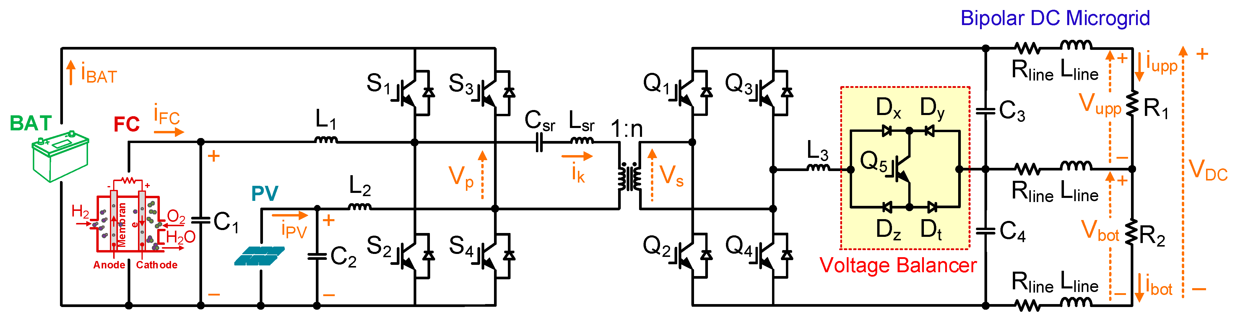
2. Proposed FPIBC System
2.1. Power Circuit
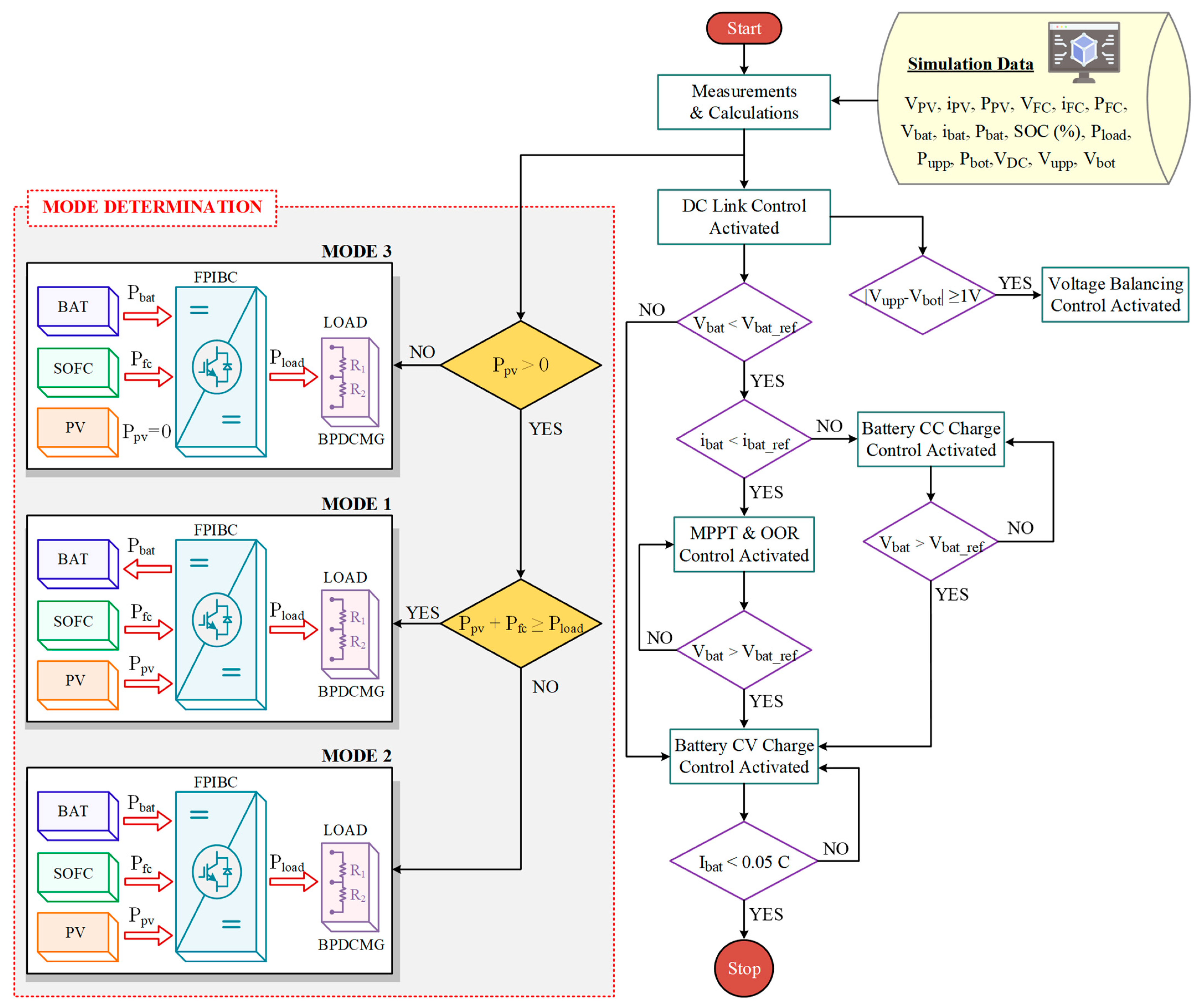
2.2. Power Sharing Modes
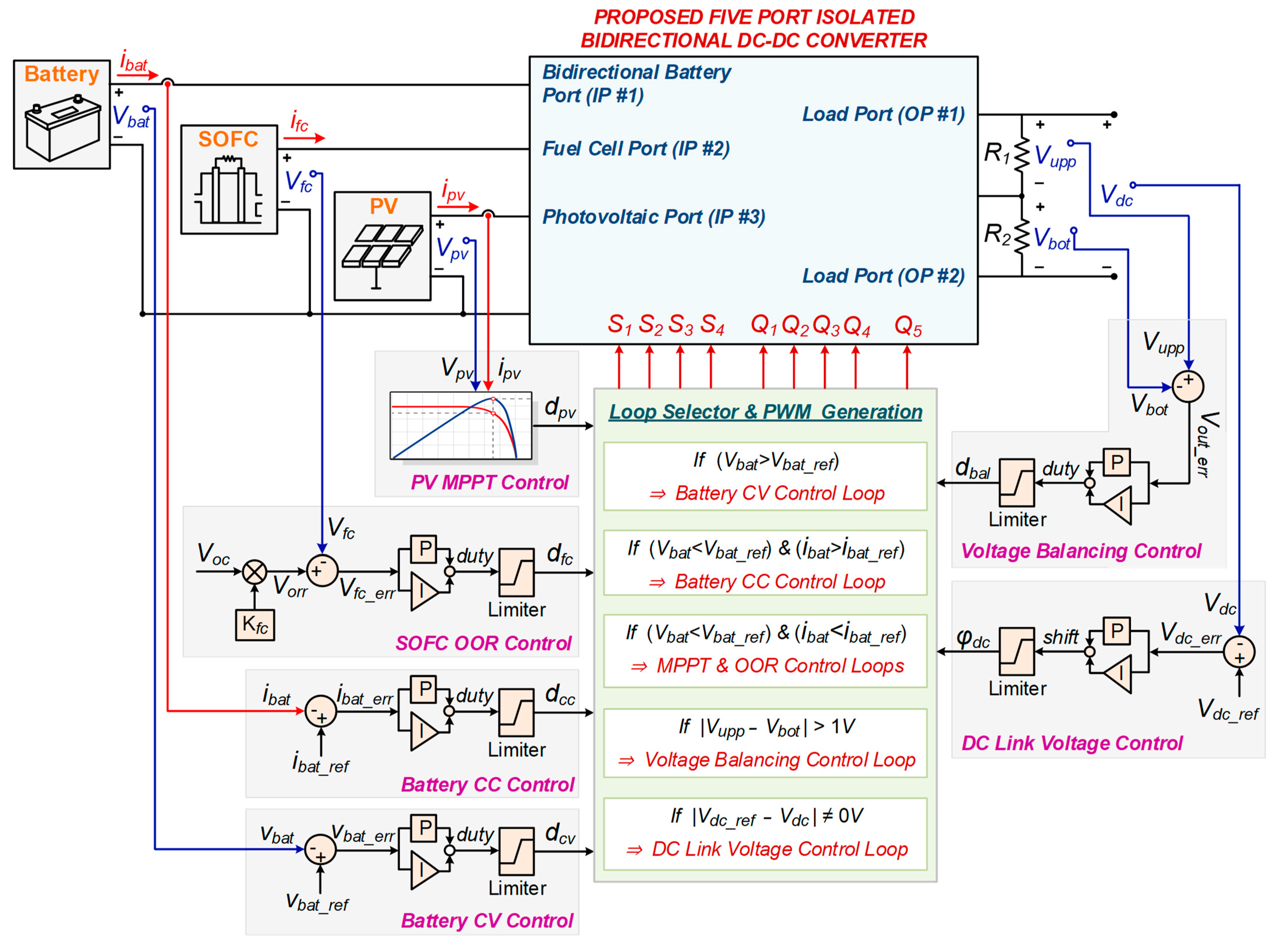
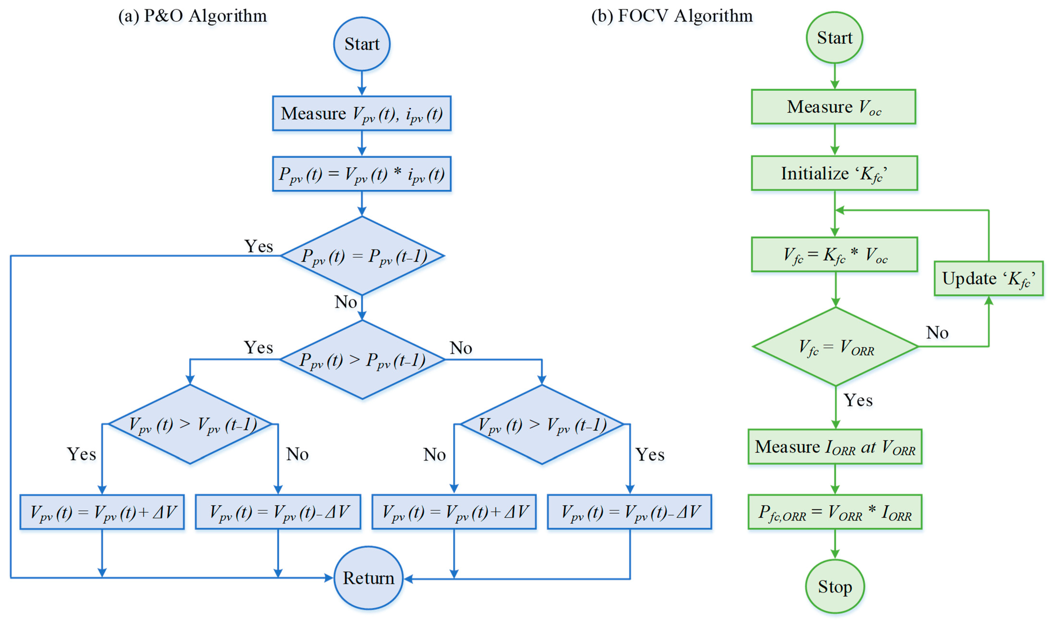
3. Controller Design
4. Simulation Results and Discussions
Comparison with Other MPCs
5. Conclusions
Author Contributions
Funding
Data Availability Statement
Acknowledgments
Conflicts of Interest
Nomenclature
| BPDCMG | Bipolar Direct Current Microgrid | C1, C2, Csr | Capacitors |
| C | Capacity | dbal | Duty Cycle of the Q5 switch |
| CC | Constant Current | dpv | Duty Cycle of the S3 and S4 Switches |
| CLLC | Capacitor–Inductor–Inductor–Capacitor | dfc | Duty Cycle of the S1 and S2 Switches |
| CV | Constant Voltage | Dx, Dy, Dz, Dt | Diodes |
| DAB | Dual Active Bridge | ibat | Charging Current |
| DC | Direct Current | Kfc | Voltage Factor |
| DCMG | Direct Current Microgrid | L1, L2, Lm, Lsr | Inductors |
| ESL | Equivalent Series Inductance | n | High-Frequency Transformer Turn Ratio |
| ESR | Equivalent Series Resistance | Pbat | Battery Power |
| ESU | Energy Storage Unit | Pfc | Fuel Cell Power |
| FB | Full Bridge | Pload | Load Power |
| FC | Fuel Cell | Ppv | PV Power |
| FOCV | Fractional Open-Circuit Voltage | S1, S2, S3, S4 | Primary Side Switches |
| FP | Fuel Pressure | Q1, Q2, Q3, Q4, Q5 | Secondary Side Switches |
| FPIBC | Five-Port Isolated Bidirectional Converter | Vbat | Battery Voltage |
| HB | Half-Bridge | VDC | Dc-Link Voltage |
| HFT | High Frequency Transformer | Vfc | Fuel Cell Voltage |
| LC | Inductor–Capacitor | Voc | Open-Circuit Voltage of the Fuel Cell |
| LLC | Inductor–Inductor–Capacitor | VORR | Reference Voltage of the Fuel Cell |
| MOSFET | Metal Oxide Semiconductor Field Effect Transistor | Vpv | PV Voltage |
| MPC | Multiport Converter | Vupp | Upper Load Voltage |
| MPPT | Maximum Power Point Tracking | Vbot | Bottom Load Voltage |
| NPC | Neutral-Point Clamped | ||
| OOR | Optimum Operation Region | ||
| OT | Operating Temperature | ||
| P&O | Perturb and Observe | ||
| PI | Proportional Integrator | ||
| PVBHPS | PV–Battery Hybrid Power System | ||
| PV | Photovoltaic | ||
| RES | Renewable Energy Source | ||
| SEPIC | Single-Ended Primary-Inductor Converter | ||
| TPC | Three-Port Converter | ||
| V2H | Vehicle-to-Home | ||
| ZCS | Zero-Current Switching | ||
| ZVS | Zero-Voltage Switching |
References
- Dragičević, T.; Lu, X.; Vasquez, J.C.; Guerrero, J.M. DC microgrids—Part II: A review of power architectures, applications, and standardization issues. IEEE Trans. Power Electron. 2016, 31, 3528–3549. [Google Scholar] [CrossRef]
- Tian, Q.; Zhou, G.; Leng, M.; Xu, G.; Fan, X. A nonisolated symmetric bipolar output four-port converter interfacing PV-battery system. IEEE Trans. Power Electron. 2020, 35, 11731–11744. [Google Scholar] [CrossRef]
- Askarian, I.; Pahlevani, M.; Knight, A.M. Three-port bidirectional DC/DC converter for DC nanogrids. IEEE Trans. Power Electron. 2021, 36, 8000–8011. [Google Scholar] [CrossRef]
- Mohseni, P.; Hosseini, S.H.; Sabahi, M.; Jalilzadeh, T.; Maalandish, M. A new high step-up multi-input multi-output DC–DC converter. IEEE Trans. Ind. Electron. 2019, 66, 5197–5208. [Google Scholar] [CrossRef]
- Savrun, M.M.; Atay, A. Multiport bidirectional DC–DC converter for PV powered electric vehicle equipped with battery and supercapacitor. IET Power Electron. 2020, 13, 3931–3939. [Google Scholar] [CrossRef]
- Prabhakaran, P.; Agarwal, V. Novel four-port DC–DC converter for interfacing solar PV–fuel cell hybrid sources with low-voltage bipolar DC microgrids. IEEE J. Emerg. Sel. Top. Power Electron. 2020, 8, 1330–1340. [Google Scholar] [CrossRef]
- Zhang, N.; Sutanto, D.; Muttaqi, K.M. A review of topologies of three-port DC–DC converters for the integration of renewable energy and energy storage system. Renew. Sustain. Energy Rev. 2016, 56, 388–401. [Google Scholar] [CrossRef]
- Chandran, I.R.; Ramasamy, S.; Ahsan, M.; Haider, J.; Rodrigues, E.M.G. Implementation of non-isolated zeta-KY triple port converter for renewable energy applications. Electronics 2021, 10, 1681. [Google Scholar] [CrossRef]
- Danyali, S.; Moradkhani, A.; Aazami, R.; Mejbel, M.T. New dual-source high-gain ZVS DC-DC converter for integrating renewable power source and battery storage. Electr. Power Syst. Res. 2022, 213, 108740. [Google Scholar] [CrossRef]
- Senapati, L.; Garg, M.M.; Panda, A.K.; Lenka, R.K. Topology synthesis and control of integrated three-port converter for renewable energy system. Comput. Electr. Eng. 2022, 101, 107996. [Google Scholar] [CrossRef]
- Arun, S.; Ahamed, T.I.; Lakaparampil, Z.V.; Joseph, A. An autonomous solar PV system using boost TPC for energy harvesting with mode-based power flow management control. Sustain. Energy Technol. Assess. 2022, 53, 102528. [Google Scholar] [CrossRef]
- Luo, P.; Guo, L.; Xu, J.; Li, X. Analysis and design of a new non-isolated three-port converter with high voltage gain for renewable energy applications. IEEE Access 2021, 9, 115909–115921. [Google Scholar] [CrossRef]
- Liang, T.-J.; Tran, T.A.A.; Huynh, K.K.N.; Chen, K.-H.; Chen, S.-M. High step-up three-port converter for renewable energy systems. IEEE Access 2023, 11, 47432–47447. [Google Scholar] [CrossRef]
- Kolahian, P.; Tarzamni, H.; Nikafrooz, A.; Hamzeh, M. Multiport DC–DC converter for bipolar medium voltage DC micro-grid applications. IET Power Electron. 2019, 12, 1841–1849. [Google Scholar] [CrossRef]
- Swaminathan, N.; Cao, Y. An overview of high-conversion high-voltage DC–DC converters for electrified aviation power distribution system. IEEE Trans. Transp. Electrif. 2020, 6, 1740–1754. [Google Scholar] [CrossRef]
- Wu, H.; Sun, K.; Zhu, L.; Xing, Y. An interleaved half-bridge three-port converter with enhanced power transfer capability using three-leg rectifier for renewable energy applications. IEEE J. Emerg. Sel. Top. Power Electron. 2016, 4, 606–616. [Google Scholar] [CrossRef]
- Sankarananth, S.; Sivaraman, P. Performance enhancement of multi-port bidirectional DC-DC converter using resilient backpropagation neural network method. Sustain. Comput. Inform. Syst. 2022, 36, 100783. [Google Scholar] [CrossRef]
- Chaudhury, T.; Kastha, D. A high gain multiport DC–DC converter for integrating energy storage devices to DC microgrid. IEEE Trans. Power Electron. 2020, 35, 10501–10514. [Google Scholar] [CrossRef]
- Zhang, J.; Jiang, W.; Jiang, T.; Shao, S.; Sun, Y.; Hu, B.; Zhang, J. A three-port LLC resonant DC/DC converter. IEEE J. Emerg. Sel. Top. Power Electron. 2019, 7, 2513–2524. [Google Scholar] [CrossRef]
- Zeng, J.; Du, X.; Yang, Z. A multiport bidirectional DC–DC converter for hybrid renewable energy system integration. IEEE Trans. Power Electron. 2021, 36, 12281–12291. [Google Scholar] [CrossRef]
- Khasim, S.R.; Dhanamjayulu, C.; Muyeen, S.M. A single inductor multi-port converter for electric vehicle applications. IEEE Access 2023, 11, 3367–3385. [Google Scholar] [CrossRef]
- Vettuparambil, A.; Chatterjee, K.; Fernandes, B.G. Dual-active-bridge-based multiport converter with split DC links. IEEE Trans. Ind. Electron. 2022, 69, 485–494. [Google Scholar] [CrossRef]
- Vettuparambil, A.; Chatterjee, K.; Fernandes, B.G. A multiport converter interfacing solar photovoltaic modules and energy storage with DC microgrid. IEEE Trans. Ind. Electron. 2021, 68, 3113–3123. [Google Scholar] [CrossRef]
- Kakigano, H.; Miura, Y.; Ise, T. Low-voltage bipolar-type DC microgrid for super high quality distribution. IEEE Trans. Power Electron. 2010, 25, 3066–3075. [Google Scholar] [CrossRef]
- Ahmadi, T.; Rokrok, E.; Hamzeh, M. Mitigation of voltage unbalances in bipolar DC microgrids using three-port multidirectional DC-DC converters. J. Power Electron. 2018, 18, 1223–1234. [Google Scholar] [CrossRef]
- Tavakoli, S.D.; Khajesalehi, J.; Hamzeh, M.; Sheshyekani, K. Decentralised voltage balancing in bipolar dc microgrids equipped with trans-z-source interlinking converter. IET Renew. Power Gener. 2016, 10, 703–712. [Google Scholar] [CrossRef]
- Pires, V.F.; Cordeiro, A.; Foito, D.; Silva, J.F.A. Dual output and high voltage gain DC-DC converter for PV and fuel cell generators connected to DC bipolar microgrids. IEEE Access 2021, 9, 157124–157133. [Google Scholar] [CrossRef]
- Lee, J.-Y.; Cho, Y.-P.; Jung, J.-H. Single-stage voltage balancer with high-frequency isolation for bipolar LVDC distribution system. IEEE Trans. Ind. Electron. 2020, 67, 3596–3606. [Google Scholar] [CrossRef]
- Liu, C.; Zhu, D.; Zhang, J.; Liu, H.; Cai, G. A bidirectional dual buck-boost voltage balancer with direct coupling based on a burst-mode control scheme for low-voltage bipolar-type DC microgrids. J. Power Electron. 2015, 15, 1609–1618. [Google Scholar] [CrossRef]
- Wang, F.; Lei, Z.; Xu, X.; Shu, X. Topology deduction and analysis of voltage balancers for DC microgrid. IEEE J. Emerg. Sel. Top. Power Electron. 2017, 5, 672–680. [Google Scholar] [CrossRef]
- Li, B.; Fu, Q.; Mao, S.; Zhao, X.; Xu, D.; Gong, X.; Wang, Q. DC/DC converter for bipolar LVDC system with integrated voltage balance capability. IEEE Trans. Power Electron. 2021, 36, 5415–5424. [Google Scholar] [CrossRef]
- Prabhakaran, P.; Agarwal, V. Novel boost-sepic type interleaved DC–DC converter for mitigation of voltage imbalance in a low-voltage bipolar dc microgrid. IEEE Trans. Ind. Electron. 2020, 67, 6494–6504. [Google Scholar] [CrossRef]
- Ahmadi, T. Voltage unbalances mitigation in bipolar DC microgrids using a novel three-port multidirectional buck–boost converter. IET Power Electron. 2021, 14, 192–200. [Google Scholar] [CrossRef]
- Ahmadi, T.; Rokrok, E.; Hamzeh, M. Supervisory control of bipolar DC microgrids equipped with three-port multidirectional DC–DC converter for efficiency and system damping optimization. Sustain. Energy Grids Netw. 2018, 16, 327–340. [Google Scholar] [CrossRef]
- Tian, Q.; Zhou, G.; Li, H.; Yang, Y.; Zhou, D. Symmetrical bipolar output isolated four-port converters based on center-tapped winding for bipolar DC bus applications. IEEE Trans. Power Electron. 2022, 37, 2338–2351. [Google Scholar] [CrossRef]
- Savrun, M.M.; Inci, M.; Buyuk, M. Design and analysis of a high energy efficient multi-port DC-DC converter interface for fuel cell/battery electric vehicle-to-home (V2H) system. J. Energy Storage 2022, 45, 103755. [Google Scholar] [CrossRef]
- Gücin, T.N.; Biberoğlu, M.; Fincan, B. Constant frequency operation of parallel resonant converter for constant-current constant-voltage battery charger applications. J. Mod. Power Syst. Clean Energy 2019, 7, 186–199. [Google Scholar] [CrossRef]
- Alonso, J.M.; Perdigão, M.S.; Vaquero, D.G.; Calleja, A.J.; Saraiva, E.S. Analysis, design, and experimentation on constant-frequency DC-DC resonant converters with magnetic control. IEEE Trans. Power Electron. 2012, 27, 1369–1382. [Google Scholar] [CrossRef]
- Mishima, T.; Mizutani, H.; Nakaoka, M. A sensitivity-improved PFM LLC resonant full-bridge DC–DC converter with LC antiresonant circuitry. IEEE Trans. Power Electron. 2017, 32, 310–324. [Google Scholar] [CrossRef]
- Jean-Pierre, G.; Shafei, A.E.; Altin, N.; Nasiri, A. A multiport bidirectional LLC resonant converter for grid-tied photovoltaic-battery hybrid system. Int. J. Renew. Energy Res. 2020, 10, 862–870. [Google Scholar] [CrossRef]
- Li, X.; Bhat, A.K.S. Analysis and design of high-frequency isolated dual-bridge series resonant DC/DC converter. IEEE Trans. Power Electron. 2010, 25, 850–862. [Google Scholar] [CrossRef]
- Karami, N.; Moubayed, N.; Outbib, R. General review and classification of different MPPT techniques. Renew. Sustain. Energy Rev. 2017, 68, 1–18. [Google Scholar] [CrossRef]
- Luta, D.N.; Raji, A.K. Comparing fuzzy rule-based and fractional open circuit voltage MPPT techniques in a fuel cell stack. Int. J. Eng. Technol. 2019, 8, 402–411. [Google Scholar] [CrossRef]
- Chapparya, V.; Dey, A.; Singh, S.P. A novel non-isolated boost-zeta interleaved DC-DC converter for low voltage bipolar DC micro-grid application. IEEE Trans. Ind. Appl. 2023, 59, 6182–6192. [Google Scholar] [CrossRef]
- Gunawardena, P.; Hou, N.; Nayanasiri, D.; Li, Y. A dual-input single-output DC-DC converter topology for renewable energy applications. IEEE Trans. Ind. Appl. 2023, 59, 1995–2006. [Google Scholar] [CrossRef]
- Saafan, A.A.; Khadkikar, V.; Edpuganti, A.; Moursi, M.S.E.; Zeineldin, H.H. A novel non-isolated four-port converter for flexible DC microgrid operation. IEEE Trans. Ind. Electron. 2024, 71, 1653–1664. [Google Scholar] [CrossRef]
- Saafan, A.; Khadkikar, V.; Moursi, M.S.E.; Zeineldin, H.H. A new multiport DC-DC converter for DC microgrid applications. IEEE Trans. Ind. Appl. 2023, 59, 601–611. [Google Scholar] [CrossRef]
- Uno, M.; Sato, M.; Tada, Y.; Iyasu, S.; Kobayashi, N.; Hayashi, Y. Partially isolated multiport converter with automatic current balancing interleaved PWM converter and improved transformer utilization for EV batteries. IEEE Trans. Transp. Electrif. 2023, 9, 1273–1288. [Google Scholar] [CrossRef]
- Kougioulis, I.; Pal, A.; Wheeler, P.; Ahmed, M.R. An isolated multiport DC-DC converter for integrated electric vehicle on-board charger. IEEE J. Emerg. Sel. Top. Power Electron. 2023, 11, 4178–4198. [Google Scholar] [CrossRef]


| Switching States | Operating Conditions | Switching Conditions | |||
|---|---|---|---|---|---|
| Mode | Imbalance | S1, S2, S3, S4 | Q1, Q2, Q3, Q4 | Q5 | |
| 1 | 1, 2 | No | 0110 | 0110 | 0 |
| 2 | 1, 2 | No | 1010 | 1001 | 0 |
| 3 | 1, 2 | No | 1010 | 0110 | 0 |
| 4 | 1, 2 | No | 1001 | 0110 | 0 |
| 5 | 1, 2 | No | 1001 | 1001 | 0 |
| 6 | 1, 2, 3 | Yes | 0110 | 1001 | 1/0 |
| 7 | 1, 2, 3 | Yes | 0110 | 0110 | 1/0 |
| 8 | 1, 2, 3 | Yes | 1010 | 1001 | 1/0 |
| 9 | 1, 2, 3 | Yes | 1010 | 0110 | 1/0 |
| 10 | 1, 2, 3 | Yes | 1001 | 0110 | 1/0 |
| 11 | 1, 2, 3 | Yes | 1001 | 1001 | 1/0 |
| System | Parameter | Value |
|---|---|---|
| PV | PV maximum power (25 °C and 1000 W/m2) | 3696 W |
| Maximum power point voltage (25 °C and 1000 W/m2) | 96.0 V | |
| Maximum power point current (25 °C and 1000 W/m2) | 38.5 A | |
| PV maximum power (25 °C and 500 W/m2) | 1890 W | |
| Maximum power point voltage (25 °C and 500 W/m2) | 97.9 V | |
| Maximum power point current (25 °C and 500 W/m2) | 19.3 A | |
| PV capacitor (C2) | 6 mF | |
| Battery | Capacity (1C) | 10.8 Ah |
| Nominal voltage | 140 V | |
| SOFC | Nominal power rating | 3750 W |
| Maximum power rating | 4200 W | |
| Nominal stack efficiency (ηFC) | 52% | |
| Nominal operating point (In, Vn) | 35.2 A, 106.5 V | |
| Maximum operating point (Im, Vm) | 40 A, 104.86 V | |
| Number of cells | 119 | |
| Nominal operating temperature (OT) | 923 °K | |
| Nominal fuel pressure (FP) | 1.35 bar | |
| SOFC capacitor (C1) | 6 mF | |
| Resonant Converter | Resonant converter inductor (Lsr) | 25 μH |
| Resonant converter capacitor (Csr) | 45 nF | |
| Resonance frequency (fr) | ~150 kHz | |
| Switching frequency (fs) | 150 kHz | |
| Transformer turns ratio (n) | 1:1 | |
| Magnetizing inductance (Lm) | 140 uH | |
| DC Microgrid | Load voltage (VDC) | 200 V |
| Upper side load voltage (Vupp) | 100 V | |
| Bottom side load voltage (Vbot) | 100 V | |
| Line resistance (Rline) | 0.4 Ω | |
| Line inductance (Lline) | 200 µH | |
| Circuit Parameters | C3 = C4 | 1 mF |
| L1 = L2 | 2 mH | |
| L3 | 18 uH | |
| MATLAB | Discrete-time digital controller sampling time | 5 × 10⁻⁷ s |
| Time Interval | Fuel Cell Parameters | PV System Parameters | Unbalanced Load Cond. | Load Power (Pupp, Pbot) | Operation Mode | |
|---|---|---|---|---|---|---|
| Case #1 | t = 1–4 s | OT = 973 K | Amb. T. = 25 °C | No | Pupp = 2400 W | Mode 1 |
| FP = 1.35 bar | Irr. = 400 W/m2 | Pbot = 2400 W | ||||
| t = 4–5 s | OT = 973 K | Amb. T. = 25 °C | No | Pupp = 3200 W | Mode 2 | |
| FP = 1.15 bar | Irr. = 400 W/m2 | Pbot = 3200 W | ||||
| t = 5–6 s | OT = 923 K | Amb. T. = 25 °C | No | Pupp = 3200 W | Mode 2 | |
| FP = 1.0 bar | Irr. = 400 W/m2 | Pbot = 3200 W | ||||
| t = 6–7 s | OT = 923 K | Amb. T. = 25 °C | No | Pupp = 2900 W | Mode 2 | |
| FP = 1.0 bar | Irr. = 400 W/m2 | Pbot = 2900 W | ||||
| t = 7–8 s | OT = 923 K | Amb. T. = 25 °C | No | Pupp = 2700 W | Mode 2 | |
| FP = 1.35 bar | Irr. = 400 W/m2 | Pbot = 2700 W | ||||
| Case #2 | t = 1–3 s | OT = 973 K | Amb. T. = 25 °C | No | Pupp = 2200 W | Mode 1 |
| FP = 1.15 bar | Irr. = 600 W/m2 | Pbot = 2200 W | ||||
| t = 3–5 s | OT = 973 K | Amb. T. = 25 °C | Yes | Pupp = 3700 W | Mode 2 | |
| FP = 1.15 bar | Irr. = 600 W/m2 | Pbot = 3200 W | ||||
| t = 5–6 s | OT = 973 K | Amb. T. = 25 °C | No | Pupp = 3000 W | Mode 1 | |
| FP = 1.15 bar | Irr. = 1000 W/m2 | Pbot = 3000 W | ||||
| t = 6–8 s | OT = 973 K | Amb. T. = 25 °C | Yes | Pupp = 2400 W | Mode 1 | |
| FP = 1.15 bar | Irr. = 1000 W/m2 | Pbot = 2500 W | ||||
| Case #3 | t = 1–3 s | OT = 973 K | Amb. T. = 25 °C | Yes | Pupp = 3300 W | Mode 2 |
| FP = 1.1 bar | Irr. = 500 W/m2 | Pbot = 2850 W | ||||
| t = 3–5 s | OT = 973 K | Amb. T. = 25 °C | Yes | Pupp = 3000 W | Mode 1 | |
| FP = 1.1 bar | Irr. = 800 W/m2 | Pbot = 3250 W | ||||
| t = 5–7 s | OT = 973 K | Amb. T. = 25 °C | Yes | Pupp = 3250 W | Mode 3 | |
| FP = 1.1 bar | Irr. = 0 W/m2 | Pbot = 2600 W | ||||
| t = 7–8 s | OT = 923 K | Amb. T. = 35 °C | Yes | Pupp = 3150 W | Mode 2 | |
| FP = 1.0 bar | Irr. = 300 W/m2 | Pbot = 2200 W |
| Topology | Isolated/Non-Isolated | Bipolar Output Voltage | Unidirectional/Bidirectional | Port Number | Number of Circuit Elements | Maximum Efficiency | ||
|---|---|---|---|---|---|---|---|---|
| Transformer (Total Windings) | Switch | Diode | ||||||
| [32] | Non-isolated | Yes | Bidirectional | 3 | None | 4 | - | 96.10% |
| [33] | Non-isolated | Yes | Unidirectional | 3 | None | 7 | - | NA |
| [44] | Non-isolated | Yes | Unidirectional | 3 | None | 2 | 2 | 95.61% |
| [6] | Non-isolated | Yes | Unidirectional | 4 | None | 2 | 4 | 93.00% |
| [2] | Non-isolated | Yes | Bidirectional | 4 | None | 3 | 4 | 95.80% |
| [21] | Non-isolated | No | Bidirectional | 4 | None | 4 | 4 | NA |
| [46] | Non-isolated | No | Bidirectional | 4 | None | 4 | 1 | 97.00% |
| [47] | Non-isolated | No | Bidirectional | 5 | None | 4 | 0 | NA |
| [16] | Isolated | No | Bidirectional | 3 | 2 (4 windings) | 4 | 6 | 96.80% |
| [18] | Isolated | No | Bidirectional | 3 | 1 (2 windings) | 10 | - | 95.96% |
| [19] | Isolated | No | Bidirectional | 3 | 1 (2 windings) | 6 | 4 | NA |
| [48] | Isolated | No | Bidirectional | 3 | 1 (2 windings) | 8 | - | 94.40% |
| [45] | Isolated | No | Unidirectional | 3 | 1 (2 windings) | 6 | 2 | 93.60% |
| [20] | Isolated | No | Bidirectional | 4 | 2 (4 windings) | 6 | 2 | 95.00% |
| [49] | Isolated | No | Bidirectional | 3 | 1 (3 windings) | 8 | 4 | 94.00% |
| [25] | Isolated | Yes | Bidirectional | 3 | 1 (3 windings) | 8 | 1 | 90.20% |
| [34] | Isolated | Yes | Unidirectional | 3 | 1 (3 windings) | 8 | 1 | NA |
| [35] | Isolated | Yes | Bidirectional | 4 | 1 (2 windings) | 6 | 4 | 95.60% |
| [14] | Isolated | Yes | Bidirectional | 5 | 1 (2 windings) | 12 | 4 | 94.70% |
| Proposed | Isolated | Yes | Bidirectional | 5 | 1 (2 windings) | 9 | 4 | 97.28% |
Disclaimer/Publisher’s Note: The statements, opinions and data contained in all publications are solely those of the individual author(s) and contributor(s) and not of MDPI and/or the editor(s). MDPI and/or the editor(s) disclaim responsibility for any injury to people or property resulting from any ideas, methods, instructions or products referred to in the content. |
© 2024 by the authors. Licensee MDPI, Basel, Switzerland. This article is an open access article distributed under the terms and conditions of the Creative Commons Attribution (CC BY) license (https://creativecommons.org/licenses/by/4.0/).
Share and Cite
Koroglu, T.; Ekici, E.; Savrun, M.M. Five-Port Isolated Bidirectional DC-DC Converter for Interfacing a Hybrid Photovoltaic–Fuel Cell–Battery System with Bipolar DC Microgrids. Electronics 2024, 13, 1036. https://doi.org/10.3390/electronics13061036
Koroglu T, Ekici E, Savrun MM. Five-Port Isolated Bidirectional DC-DC Converter for Interfacing a Hybrid Photovoltaic–Fuel Cell–Battery System with Bipolar DC Microgrids. Electronics. 2024; 13(6):1036. https://doi.org/10.3390/electronics13061036
Chicago/Turabian StyleKoroglu, Tahsin, Elanur Ekici, and M. Mustafa Savrun. 2024. "Five-Port Isolated Bidirectional DC-DC Converter for Interfacing a Hybrid Photovoltaic–Fuel Cell–Battery System with Bipolar DC Microgrids" Electronics 13, no. 6: 1036. https://doi.org/10.3390/electronics13061036
APA StyleKoroglu, T., Ekici, E., & Savrun, M. M. (2024). Five-Port Isolated Bidirectional DC-DC Converter for Interfacing a Hybrid Photovoltaic–Fuel Cell–Battery System with Bipolar DC Microgrids. Electronics, 13(6), 1036. https://doi.org/10.3390/electronics13061036