Article

Design of UWB Electrically Small Antenna Based on Distributed Passive Network Loading

1
Yangtze Delta Region Institute (Huzhou), University of Electronic Science and Technology of China, Huzhou 313000, China
2
School of Electronic Science and Engineering, University of Electronic Science and Technology of China, Chengdu 611731, China
3
National Key Laboratory of Microwave Imaging Technology, Aerospace Information Research Institute, Chinese Academy of Sciences, Beijing 100190, China
4
Science and Technology on Electronic Information Control Laboratory, Chengdu 610036, China
*
Authors to whom correspondence should be addressed.
Electronics 2024, 13(5), 914; https://doi.org/10.3390/electronics13050914
Submission received: 24 January 2024 / Revised: 19 February 2024 / Accepted: 22 February 2024 / Published: 28 February 2024

Abstract

:
In this paper, an ultra-wideband electrically small antenna based on distributed passive network loading is proposed. Based on the Vivaldi antenna theory, magnetic dipole antenna theory, and distributed loading theory, the electrically small antenna achieves the purpose of being wideband using a three-dimensional design of a planar Vivaldi antenna structure under limited space constraints. At the same time, the magnetic dipole antenna is introduced to effectively expand the low-frequency bandwidth of the electrically small antenna without increasing the aperture size. Finally, through the distributed passive network loading, the wideband-conjugated matching of the electrically small antenna is achieved without increasing the size of the electrically small antenna. The −6 dB bandwidth of the electrically small antenna is 0.2 GHz–3 GHz, and the overall size is 0.06 λ0 × 0.05 λ0 × 0.12 λ0, where λ0 is the wavelength of the lowest frequency of the antenna. One sample of the proposed UWB electrically small antenna is fabricated and tested. Good agreement between simulation results and measurement results are obtained. The design method of UWB electrically small antenna proposed in this paper can be applied to the base station antenna, low-frequency detection, microwave sensing, and microwave measurement.

1. Introduction

With the rapid development of wireless communication technology and large-scale integrated circuits, all kinds of electronic equipment are becoming smaller and smaller. Especially in the lower frequency band, the wavelength of the antenna is longer, and the size of the antenna is relatively large, so it is difficult to install on the working platform with limited space. The antenna is a key component in the front end of a communication system, and the miniaturization of antenna has affected the development of a modern wireless communication system. Therefore, in the lower frequency band, such as HF, VHF, and UHF band, the research of electrically small antenna under the constraint of a limited platform has been paid more attention by researchers. However, in the lower frequency band, the electrical length of the electrically small antenna is much smaller than its operating wavelength, the radiation resistance is much smaller than the radiation reactance, and the radiation field in the adjacent space of the antenna is also much smaller than the induction field, so that the near field energy storage is very high. In addition, the larger induced current leads to a large loss, which will result in very low radiation efficiency. Therefore, achieving antenna miniaturization while taking into account the overall performance of the antenna is a very challenging task.
Due to the lower operating frequency, the size of electrically small antenna is much smaller than the operating wavelength, resulting in more near-field energy storage of the antenna, less energy radiated out, and low efficiency, so it can be regarded as a capacitor or inductor with only a small amount of radiation [1,2]. The four most common types of electrically small antennas are short dipole antennas [3,4,5,6], electrically small monopole antennas [7,8], electrically small loop antennas [9,10], and spiral antennas [11,12,13]. For an electrically small antenna, its input impedance is very sensitive to the change of frequency, so the input impedance characteristics of the electrically small antenna determine the width of its working frequency band. However, the input resistance value of the electrically small antenna is small, and the input reactance value is large, so it has a high Q factor, resulting in a narrow band characteristic of the electrically small antenna, which is difficult to realize the wideband design.
Over the years, scholars at home and abroad have been committed to studying various methods to achieve antenna miniaturization, and the common methods are the folding method [14,15,16,17,18], slit method [19,20,21,22], fractal technology [23,24], metamaterial technology [25,26,27], etc. In addition, antenna miniaturization can be realized through passive loading technology, including impedance loading [28,29,30], medium loading [31,32], and slot loading [33,34,35]. In reference [36], an omnidirectional, vertically polarized (VP), wideband, electrically small near-field resonant parasitic (NFRP) filtenna is presented, and the construction of an inverted-F feeding structure not only reduces the electric size and expands FBW, but also achieves a high-pass filtering characteristic. In reference [37], the fundamental working principle of the quadruple inverted-F antenna (QIFA) is clearly revealed for the first time, and a unified design method is then proposed. Through mode analysis, different modes are stimulated to work at the same time, and the bandwidth and front-to-back ratio of the antenna are improved without changing the antenna size. In reference [38], a pattern-reconfigurable electrically small antenna (ESA) that radiates a circularly polarized broadside pattern and linearly polarized omnidirectional pattern is proposed. The ESA consists of four dipole arms on the top layer and five dipole arms on the bottom layer. The two layers are connected by five vertical shorting pins. The connection states between different dipole arms and pins are electrically controlled by three inserted PIN diodes to generate the equivalent even- and odd-mode states, which correspond to reconfigurable broadside and omnidirectional patterns. In reference [39], a wideband, electrically small, and near-field resonant parasitic (NFRP) dipole antenna with stable radiation performance is presented. The measured results demonstrate a wide 14.4% −10 dB impedance bandwidth along with a stable realized gain of 1.4 dBi over the entire band. Moreover, stable and uniform radiation patterns together with high radiation efficiency values were also measured. Although the above research can effectively improve the electrical characteristics of electrically small antennas, it is difficult to realize ultra-wideband impedance matching for passive electrically small antennas due to the limitation of gain–bandwidth theory.
The development of electromagnetic dipole theory and distributed loading theory provides a new way to further improve the performance of electrically small antenna. Under limited space constraints, magnetic dipole antennas can effectively extend the path of the electrically small antenna’s surface current without increasing the aperture size. At the same time, the introduction of distributed network loading can effectively improve the overall performance of the electrically small antenna without changing the size of being electrically small. In this paper, based on the theory of Vivaldi antenna and magnetic dipole antenna, the planar Vivaldi antenna is designed with three-dimensional expansion under limited space constraints, and the purpose of the wideband is achieved by making full use of three-dimensional space. Then, the three-dimensional Vivaldi antenna is further extended to form a magnetic dipole antenna, and the low-frequency bandwidth of the electrically small antenna is effectively expanded without increasing the aperture size of the electrically small antenna. Finally, through the distributed passive network loading, the conjugated matching of the electrically small antenna in a wideband is achieved, and the ultra-wideband characteristics of the electrically small antenna are realized without increasing the size of the electrically small antenna.
The contributions of this paper are (1) that an ultra-wideband electrically small antenna based on distributed passive network loading is proposed; (2) by combining the Vivaldi antenna theory, magnetic dipole antenna theory and distributed loading theory, a wideband design is realized under limited space constraints; and (3) the feasibility of this method is proved using simulation and experiment.

2. Materials and Methods

Vivaldi antenna belongs to a kind of gradual slot antenna, due to the fact that the width of its slot is constantly widening, the electromagnetic waves of different frequencies can be transmitted and received in different parts of the antenna, and the electrical performance of antenna has not changed, so a Vivaldi antenna has ultra-wideband characteristics. The Vivaldi antenna generally includes an impedance matching unit, a coupled feed unit, and a radiation unit. The main function of the impedance matching unit is to match the impedance between the antenna and the feed system. In fact, the impedance of the coaxial cable line is mostly 50 ohms, so the equivalent impedance of the antenna is designed to be 50 ohms to achieve impedance matching. The coupled feed unit is designed to be a nearly parallel structure and coupled to the microstrip line when the microstrip line is fed. The radiation unit is the most important part of the Vivaldi antenna, but also the most difficult part of the antenna design, the quality of the radiation unit directly affects the performance of the antenna.
In an ideal state, the length of the Vivaldi antenna is infinite, and its working bandwidth is also infinite, but in fact, the operating bandwidth is limited by the slot structure. The aperture width of the antenna determines the lowest working frequency, and the width of the isometric slotted line determines the highest working frequency of the antenna. In general, for Vivaldi antennas, the lower the operating frequency of the antenna, the larger the size of the antenna, and it will be more difficult to process.
The gradient line of the Vivaldi antenna is an exponential function, whose expression is
y = C 1 e R × x + C 2
where the C1 and C2 are constants and variables C1 and C2 are given using
C 1 = y 2 y 1 e R × x 2 e R × x 1
C 2 = y 1 e R × x 2 y 2 e R × x 1 e R × x 2 e R × x 1
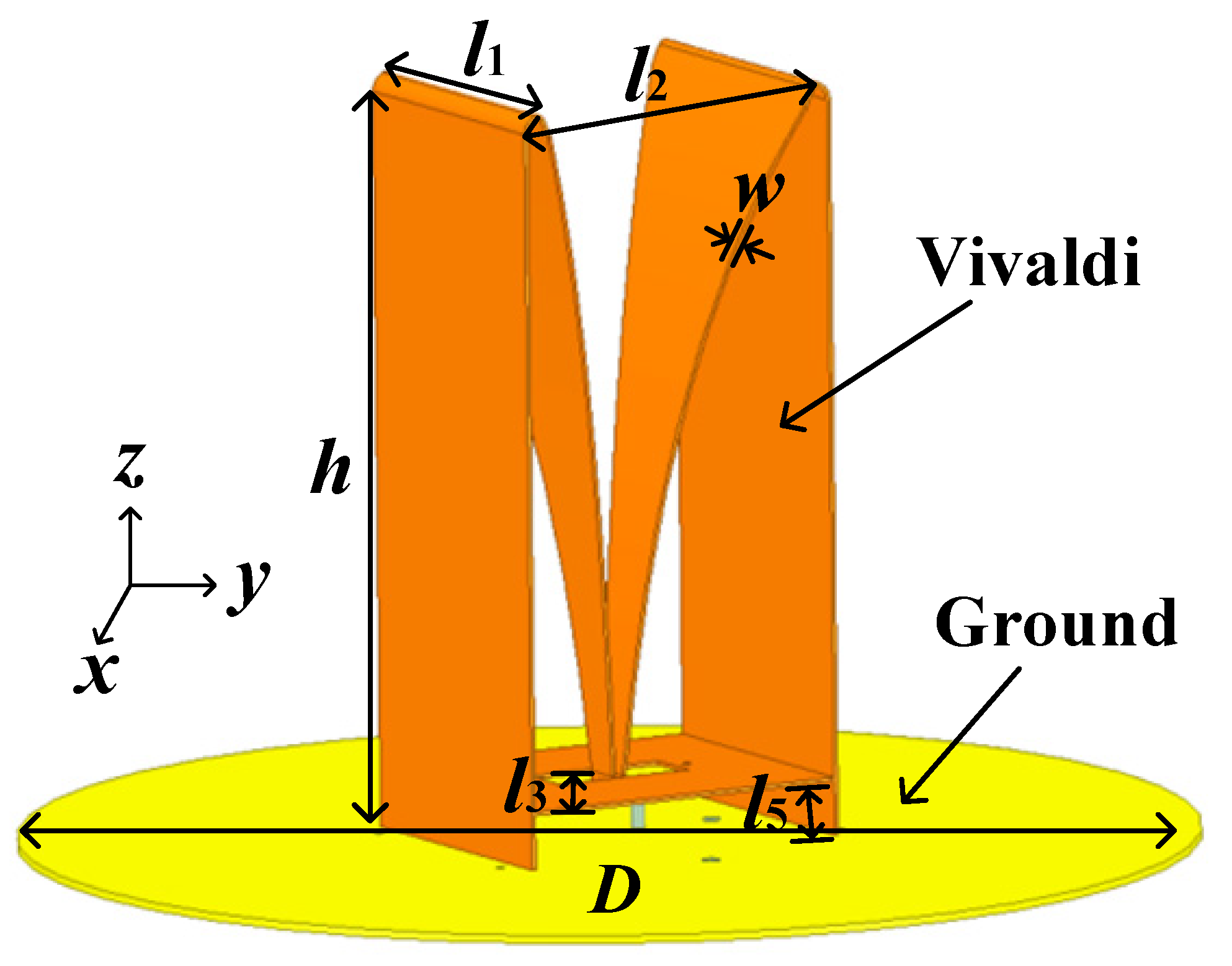
The size of the traditional planar Vivaldi antennas is generally about half a wavelength, but in practical engineering applications, it is often limited by the scene and needs to be miniaturized. The lowest operating frequency of the electrically small Vivaldi antenna is limited by the aperture width of the Vivaldi antenna, and its size is much smaller than the operating wavelength of the low-band, resulting in a relatively large low-band reactance, which is difficult to achieve ultra-wideband impedance matching through the form of a passive matching network. Furthermore, it is difficult to improve the low-frequency electrical performance through grooving or folding. In this paper, the planar Vivaldi antenna structure is extended into a three-dimensional structure, which is shown in Figure 1. The edge of the three-dimensional Vivaldi antenna in the vertical plane is designed according to the exponential form of the planar Vivaldi antenna, and the surface of the three-dimensional Vivaldi antenna in the horizontal plane gradually transitions from the bottom to the top to achieve different impedance characteristics, and the impedance of the coaxial feed port is gradually changed from 50 Ω to the free space impedance. The detailed design parameters of the structure are l1 = 75 mm, l2 = 90 mm, l3 = 6 mm, l4 = 9.8 mm, w = 1 mm, h = 194 mm, the diameter of the ground is D = 300 mm, the thickness of the ground is 2 mm. The parameters of the gradient curve are x t = A 1 e P × t + C 1 , y t = A 2 e P × t + C 2 , z t = t , where A1 = 7.72, A2 = 6.95, C1 = −6.72, C2 = −2.05, and P = 10. The material of the antenna is copper, and the material of the supporting ground is aluminum.
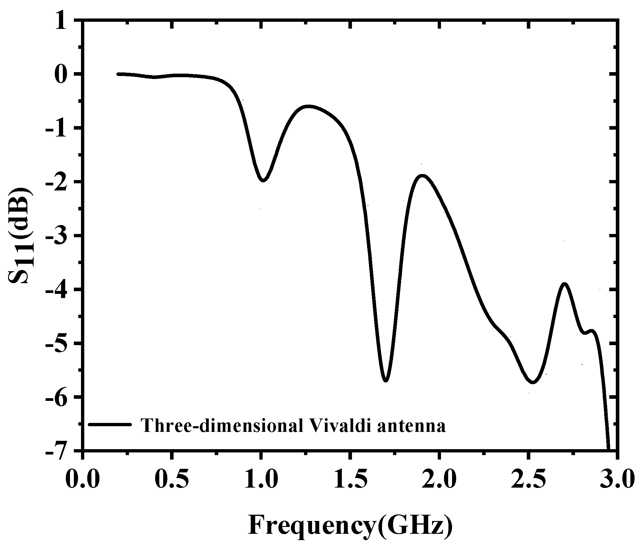
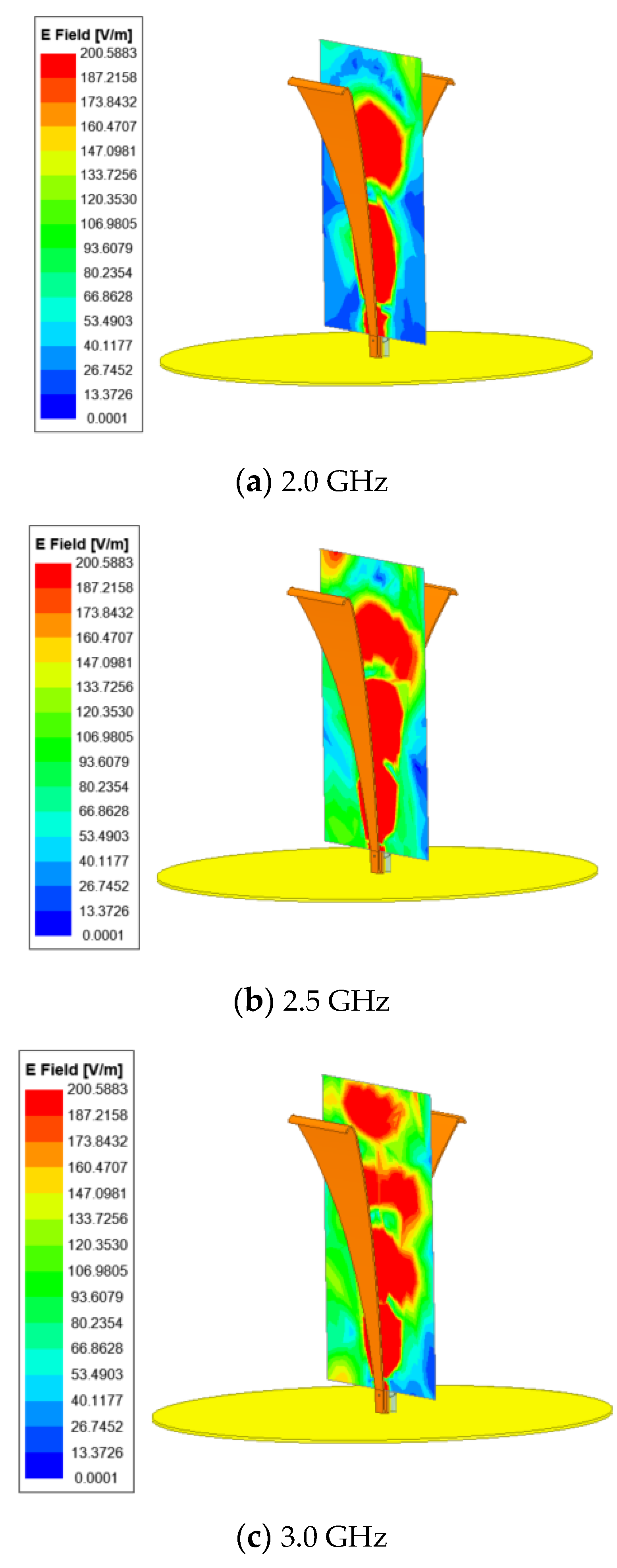
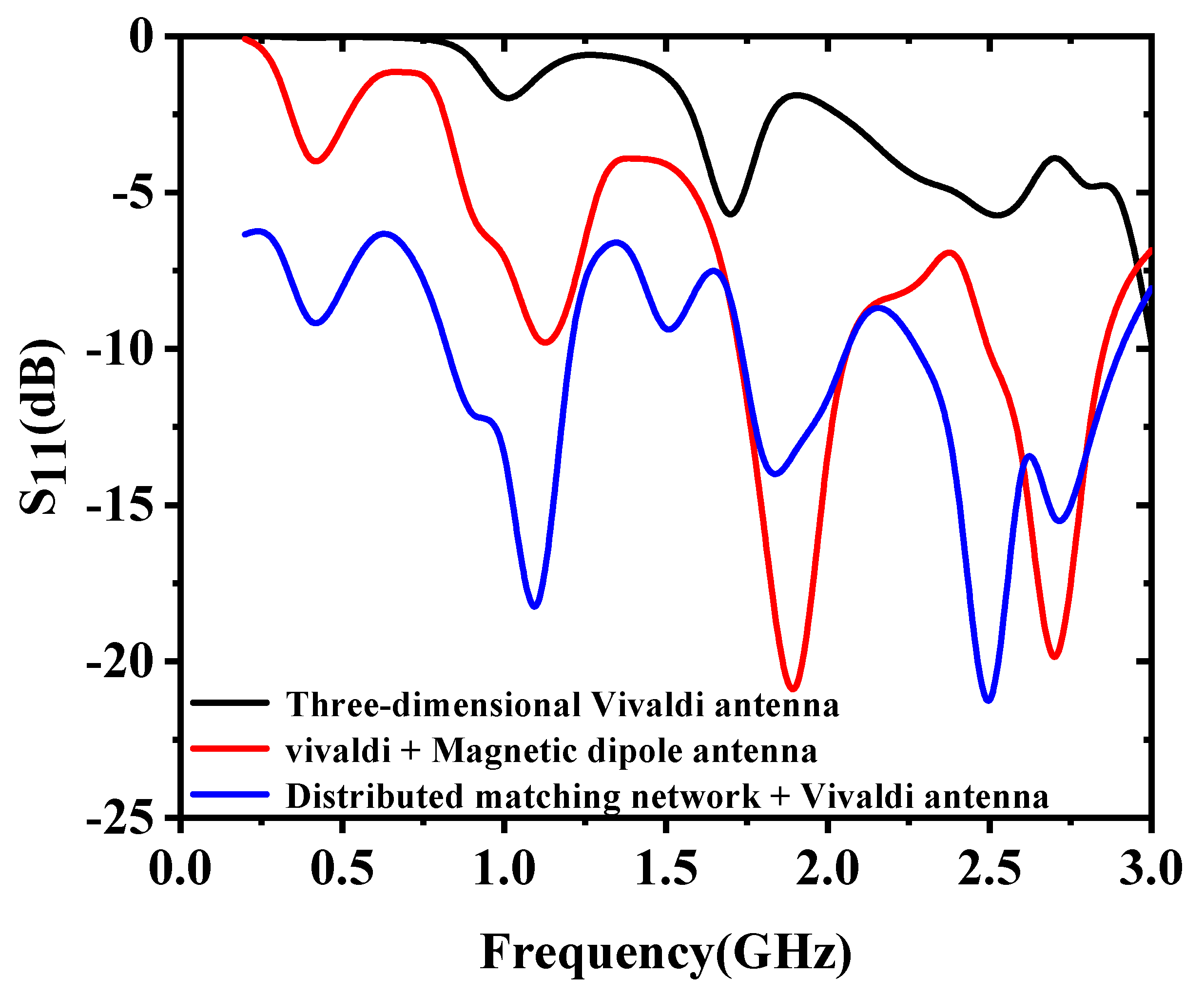
The S-parameter simulation result of the three-dimensional Vivaldi antenna is shown in Figure 2, which is simulated using ANSYS HFSS. The −6 db bandwidth of the three-dimensional Vivaldi antenna is 2.91 GHz–3.0 GHz. In the low-frequency band, the three-dimensional Vivaldi antenna has a large imaginary part of the input impedance due to the aperture limitation, resulting in poor impedance-matching characteristics of the antenna, and the energy is fully reflected back to the feed port. The three-dimensional Vivaldi antenna operates in the traveling wave mode in the high-frequency band, and its longitudinal electric field distributions are shown in Figure 3, which is consistent with the traditional planar Vivaldi antenna.
Due to the end reflection effect and size limitations, while limited by the size of the working space, the size of the three-dimensional Vivaldi antenna cannot continue to extend. In this paper, the design idea of magnetic dipole antenna is introduced, and the end of three-dimensional Vivaldi antenna is extended vertically down and connected to build a magnetic dipole resonant loop in a low-frequency band. The structure of the improved three-dimensional Vivaldi antenna is shown in Figure 4. The detailed design parameters of the structure are l1 = 75 mm, l2 = 90 mm, l3 = 6 mm, l5 = 14 mm, w = 1 mm, h = 194 mm, the diameter of the ground is D = 300 mm, the thickness of the ground is 2 mm. The parameters of the gradient curve are x t = A 1 e P × t + C 1 , y t = A 2 e P × t + C 2 , z t = t , where A1 = 7.72, A2 = 6.95, C1 = −6.72, C2 = −2.05, and P = 10.
After the introduction of the magnetic dipole structure, the S-parameter simulation results of the improved three-dimensional Vivaldi antenna are shown in Figure 5. The −6 db bandwidth of the improved three-dimensional Vivaldi antenna is 0.92 GHz–1.25 GHz and 1.63 GHz–3.0 GHz. The working bandwidth and low-frequency performance of the improved three-dimensional Vivaldi antenna are improved, but the energy is fully reflected back to the feed port near 200 MHz. The impedance-matching characteristic of three-dimensional Vivaldi antenna in the whole working band is still poor.
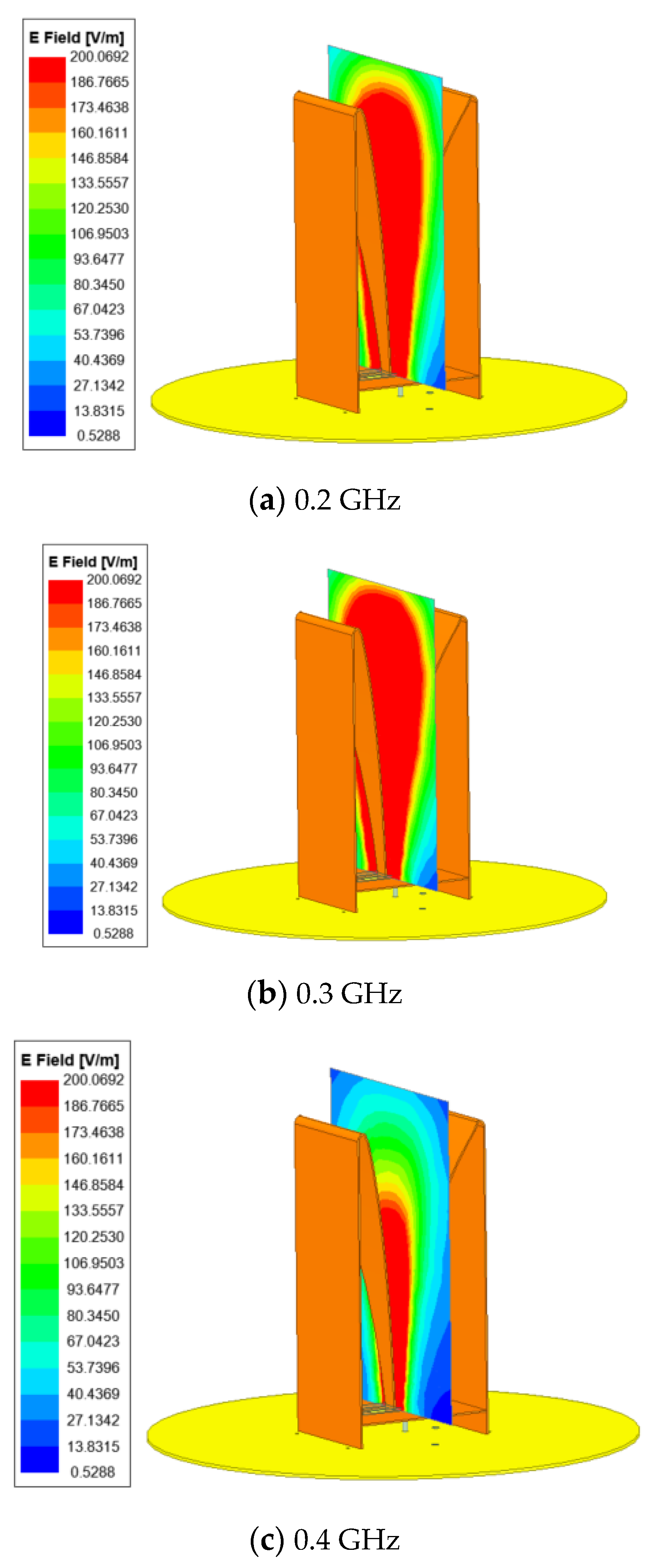
The longitudinal electric field distributions of the improved three-dimensional Vivaldi antenna are shown in Figure 6. According to the electric field distribution, it can be seen that the three-dimensional Vivaldi antenna works in the standing wave mode of the magnetic dipole in the low-frequency band, which is consistent with the expected design and helps to expand the operating frequency band.
In order to improve the impedance matching performance of electrically small Vivaldi antenna in the whole working band, this paper adopts the method of three-dimensional Vivaldi antenna based on distributed passive network loading, and introduces different capacitance and inductance effects by cutting slots on the vertical plane on both sides of the three-dimensional Vivaldi antenna and loading bending structures of different sizes in the slots. At the same time, parallel resistors are loaded at the ends of both sides of the three-dimensional Vivaldi antenna. Compared with the loading of a single resistor, the parallel resistance loading can effectively improve the current distribution at the end of the three-dimensional Vivaldi antenna, so that the surface current passes through the resistance evenly. In this way, the end reflection effect of the electrically small Vivaldi antenna’s surface current can be reduced and the bandwidth of the electrically small Vivaldi antenna can be increased.
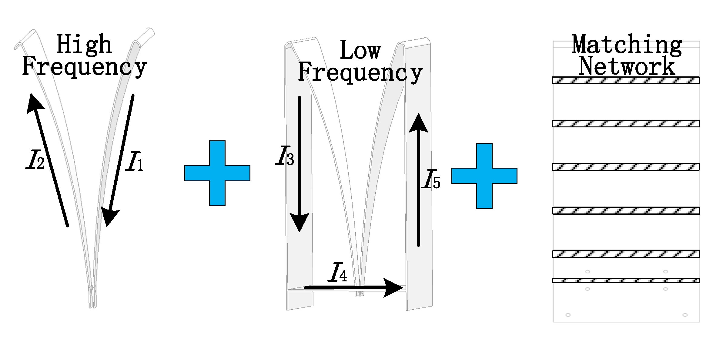
In order to solve the problem that the passive electrically small antenna cannot realize ultra-wideband impedance matching in a low-frequency band under limited space constraints, this work realizes the wideband design of electrically small antenna under limited aperture size based on the basic theories of electrically small antenna theory, Vivaldi antenna theory, wideband antenna design theory, and magnetic dipole antenna theory. The design schematic diagram of electrically small Vivaldi antenna based on distributed passive network loading is shown in Figure 7. Based on the design of planar electrically small Vivaldi antenna, a design method of three-dimensional Vivaldi antenna is proposed, using which an electrically small Vivaldi antenna will work in a high-frequency band. Then, the magnetic dipole antenna structure is introduced, using which an electrically small Vivaldi antenna will work in a low-frequency band and expand the low-frequency bandwidth. Finally, the impedance-matching characteristics of the electrically small Vivaldi antenna are improved in the whole working band by means of distributed matching network loading.
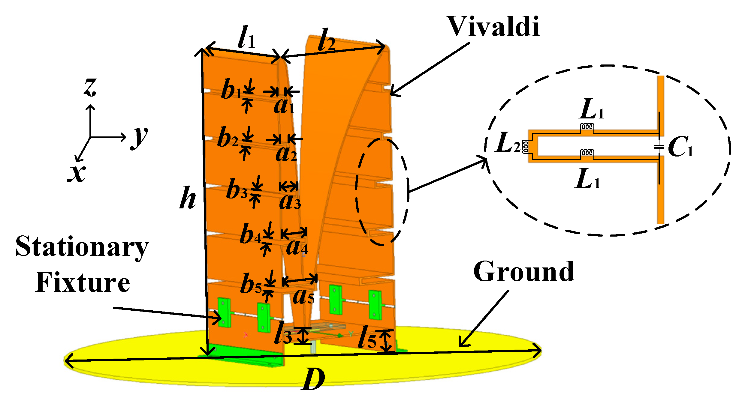
The structural model of the electrically small Vivaldi antenna based on distributed passive network loading is shown in Figure 8. Loading different bending structures can not only increase the electrical length of the electrically small Vivaldi antenna, but also introduce different capacitance and inductance effects, changing the low-frequency impedance characteristics of the electrically small Vivaldi antenna. The detailed design parameters of the structure are l1 = 75 mm, l2 = 90 mm, l3 = 6 mm, l5 = 14 mm, w = 1 mm, h = 194 mm, a1 = 7 mm, a2 = 8 mm, a3 = 14 mm, a4 = 21 mm, a5 = 28 mm, b1 = 3 mm, b2 = 3 mm, b3 = 3 mm, b4 = 3 mm, b5 = 3 mm, the diameter of the ground is D = 300 mm, the thickness of the ground is 2 mm. The parameters of the gradient curve are: x t = A 1 e P × t + C 1 , y t = A 2 e P × t + C 2 , z t = t , where A1 = 7.72, A2 = 6.95, C1 = −6.72, C2 = −2.05, and P = 10.
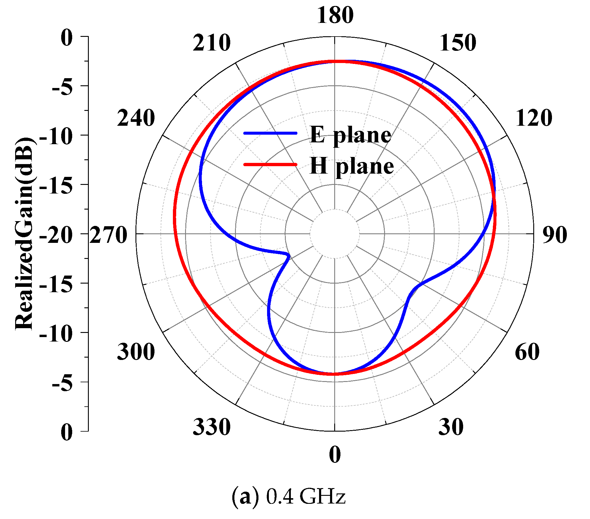
The S-parameter simulation results of the electrically small Vivaldi antenna based on distributed passive network loading are shown in Figure 9. The −6 db bandwidth of the electrically small Vivaldi antenna based on distributed passive network loading is 0.2 GHz–3.0 GHz. Through the distributed network loading, the impedance-matching characteristics of the electrically small Vivaldi antenna in the whole operating band are improved. The radiation pattern simulation results of the proposed electrically small Vivaldi antenna based on distributed passive network loading are shown in Figure 10. The realized gain of the electrically small Vivaldi antenna at 0.4 GHz is −2.05 dbi, the realized gain of the electrically small Vivaldi antenna at 1.0 GHz is 2.5 dbi, the realized gain of the electrically small Vivaldi antenna at 2.0 GHz is 7.05 dbi, and the realized gain of the electrically small Vivaldi antenna at 3.0 GHz is 8.3 dbi. In the low-frequency band, the radiation of the electrically small Vivaldi antenna is approximately omnidirectional. But, in the high-frequency band, the radiation of the electrically small Vivaldi antenna is terminal radiation, which is consistent with the theoretical design.

3. Fabrication and Measurement Results

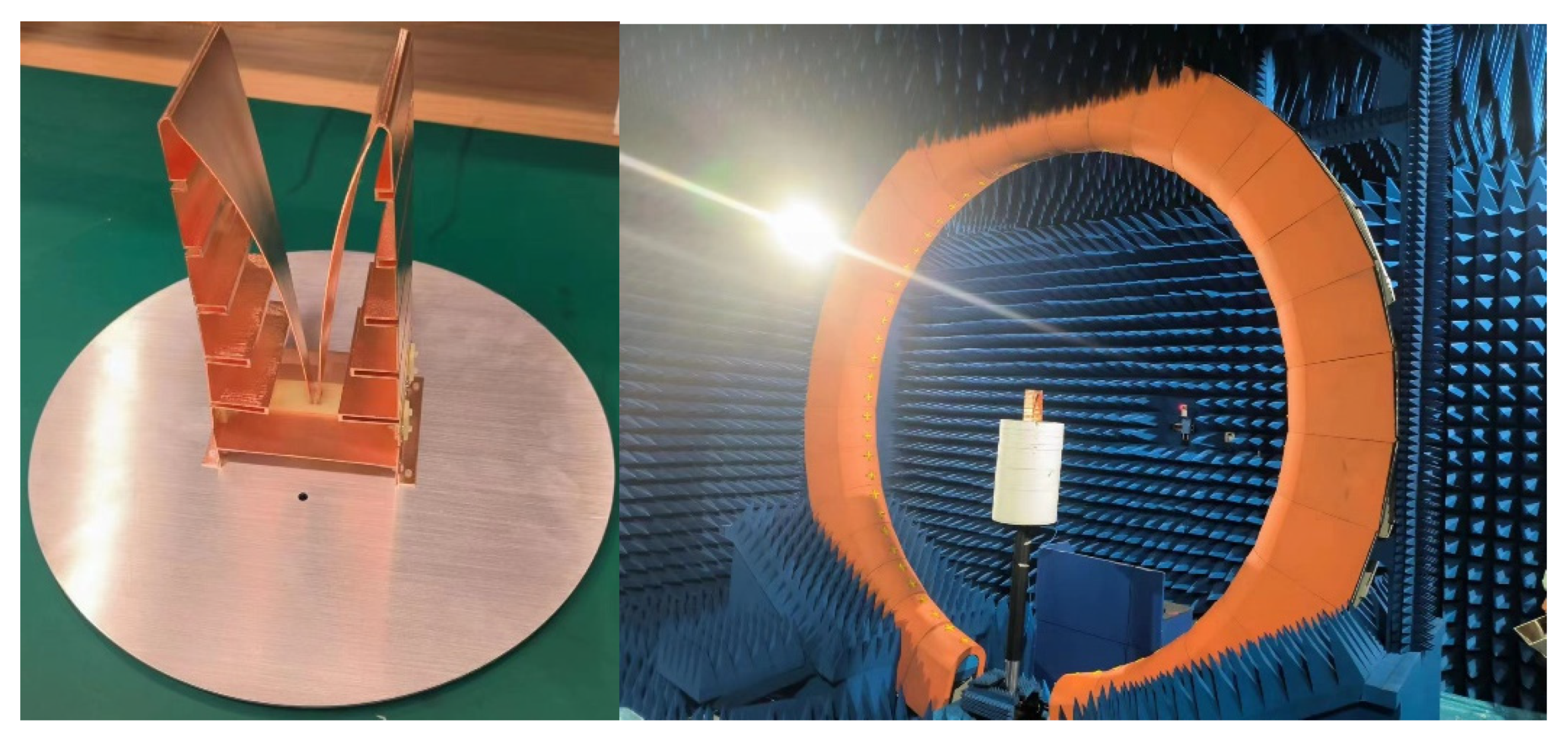
In order to evaluate the performance of the ultra-wideband electrically small antenna based on distributed passive network loading as shown in Figure 8, a prototype is fabricated and tested. The prototype material is copper, and the material of the supporting ground is aluminum, which just is a fixed device. The overall size of the electrically small Vivaldi antenna is 90 mm × 75 mm × 194 mm, and the diameter of the fixed device is 300 mm. The prototype and test scene are shown in Figure 11, and the spherical field in the microwave darkroom was used for the test. Firstly, the vector network analyzer is turned on and preheated, and calibrated by the standard gain antenna. Secondly, one port of the vector network analyzer is connected to the standard gain antenna, and the other port is connected to the electrically small Vivaldi antenna under test, then save and record the far field pattern information of the electrically small Vivaldi antenna under test. Finally, the pattern of electrically small Vivaldi antenna is obtained by comparison method.
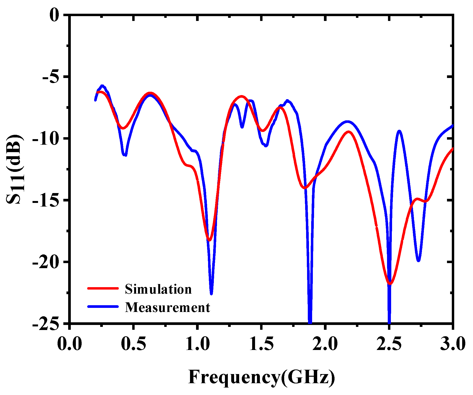
Figure 12 shows the S-parameter measurement results of the electrically small Vivaldi antenna based on distributed passive network loading. The −6 db bandwidth of the electrically small Vivaldi antenna based on distributed passive network loading is 0.2 GHz–3 GHz, and a good matching effect is achieved in the entire operating frequency band. The radiation pattern measurement results of the electrically small Vivaldi antenna based on distributed passive network loading are shown in Figure 13. According to the measurement results, the electrically small Vivaldi antenna operates in magnetic dipole mode in the low-frequency band, and the radiation pattern is approximately omnidirectional radiation, while the electrically small Vivaldi antenna operates in the traveling wave mode in the high-frequency band, and the radiation pattern is end-directional radiation. The measurement results are in good agreement with the simulation results, and the ultra-wideband electrical characteristic of the electrically small Vivaldi antenna is obtained.
A comparison of the proposed electrically small Vivaldi antenna with other works is listed in Table 1. It can be seen that this work exhibits the widest bandwidth, relatively high gain, as well as minimum aperture size compared with recently reported miniaturized antennas. As compared with the antenna in [18,39], it has the advantages of a much smaller aperture size and a higher octave. As compared with the antenna in [22], although the bandwidth is not advantageous, the antenna size is much smaller. As compared with the antenna in [37], the antenna type is different from it, and in the case of comparable size, a wider bandwidth is achieved.

4. Conclusions

In this paper, electrically small Vivaldi antenna based on distributed matching network loading has been designed and analyzed using Vivaldi antenna theory, magnetic dipole antenna theory, and distributed loading theory. The electrically small Vivaldi antenna operates in a frequency band of 0.2 GHz–3 GHz, and the overall size is 0.06 λ0 × 0.05 λ0 × 0.12 λ0. One sample of the proposed electrically small Vivaldi antenna is fabricated and tested. The simulation results agree well with the measurement results. This electrically small Vivaldi antenna has the advantages of a small size, low loss, and ultra-wideband, which can be used for the base station antenna, low-frequency detection, microwave sensing, and microwave measurement.
Our future work will focus on the problem of lower profile height of the electrically small Vivaldi antenna, and further broaden the low-frequency bandwidth of the electrically small Vivaldi antenna by combining it with traditional slot and dielectric loading methods. In addition, the integrated design of the electrically small Vivaldi antenna feed and radiator will be studied to reduce the discontinuity at the feed port and further improve the overall performance of the electrically small Vivaldi antenna.

Author Contributions

Conceptualization, Z.C., X.L. and Y.L.; methodology, Z.C. and X.H.; validation, Z.C. and X.Y.; investigation, Z.C. and G.L.; writing—original draft preparation, Z.C.; writing—review and editing, Z.C. All authors have read and agreed to the published version of the manuscript.

Funding

This research was funded by National Natural Science Foundation of China under Grant No. 62271122, and in part by Scientific Research Foundation for Yangtze Delta Region Institute of University of Electronic Science and Technology of China, Huzhou, under Grant Nos. U03220080, P0121003 and U05220004.

Data Availability Statement

The data that support the findings of this study are available within the article.

Conflicts of Interest

The authors declare no conflicts of interest.

References

  1. Kim, O.S.; Breinbjerg, O.; Yaghjian, A.D. Electrically Small Magnetic Dipole Antennas with Quality Factors Approaching the Chu Lower Bound. IEEE Trans. Antennas Propag. 2010, 58, 1898–1906. [Google Scholar] [CrossRef]
  2. Kim, O.S.; Breinbjerg, O. Lower bound for the radiation Q of electrically small magnetic Dipole antennas with solid magneto dielectric core. IEEE Trans. Antennas Propag. 2011, 59, 679–681. [Google Scholar] [CrossRef]
  3. Wang, Y.Y.; Yang, S. Design of an Electrically Small 3-D Antenna with Quasi-Isotropic Radiation Pattern. IEEE Antennas Wirel. Propag. Lett. 2021, 20, 1873. [Google Scholar] [CrossRef]
  4. Sonapreetha, M.R.; Geonyeong, S.; Wonkyo, K.; Syed, I.H.S.; Yoon, I.J. Design and Verification of an Electrically Small, Extremely Thin Dual-Band Quasi-Isotropic Antenna. IEEE Antennas Wirel. Propag. Lett. 2020, 19, 2482. [Google Scholar]
  5. Kawamura, T.; Matsushita, T.; Kondo, T.; Takeuchi, F.; Hongo, K. Formulae for the Impedance and Transmission Factor of an Electrically Small Half-Sheath Dipole Antenna Immersed in Seawater. IEEE Antennas Wirel. Propag. Lett. 2022, 21, 640. [Google Scholar] [CrossRef]
  6. Tang, M.C.; Wu, Z.T.; Shi, T. Dual-Band, Linearly Polarized, Electrically Small Huygens Dipole Antennas. IEEE Trans. Antennas Propag. 2019, 67, 640. [Google Scholar] [CrossRef]
  7. Narbudowicz, A.; Zandamela, A.; Marchetti, N. Energy-Efficient Dynamic Directional Modulation with Electrically Small Antennas. IEEE Antennas Wirel. Propag. Lett. 2022, 21, 681. [Google Scholar] [CrossRef]
  8. Hiroshi, U.; Nobuki, H.; Hiromichi, Y. Artificial Magnetic Conductor with Electric Walls and Its Application to Small Antenna Functional on Metal Surfaces. IEEE Trans. Antennas Propag. 2021, 69, 5315. [Google Scholar]
  9. Chen, Z.; Hu, W.; Gao, Y.C.; Wen, L.H.; Li, C.J.; Hu, Z.P.; Jiang, W.; Gao, S. Compact Wideband Circularly Polarized Loop Antenna Based on Dual Common and Differential Modes. IEEE Antennas Wirel. Propag. Lett. 2022, 21, 1567. [Google Scholar] [CrossRef]
  10. Lee, S.H.; Shin, G.; Sonapreetha, M.R.; Choi, J.Y.; Yoon, I.J. Low-Profile, Electrically Small Planar Huygens Source Antenna with an Endfire Radiation Characteristic. IEEE Antennas Wirel. Propag. Lett. 2019, 18, 412. [Google Scholar] [CrossRef]
  11. Bush, J.D.; Arumugam, D.D.; Feyissa, B. Counter-Wound Normal-Mode Helical Antenna as an Electrically Small Electro-Quasi-Static Exciter. IEEE Antennas Wirel. Propag. Lett. 2020, 19, 287. [Google Scholar] [CrossRef]
  12. Yang, Y.; Gong, Y.B.; Guo, K. Broad-Band Multiple OAMs’ Generation with Eight-Arm Archimedean Spiral Antenna (ASA). IEEE Access 2020, 8, 53232. [Google Scholar] [CrossRef]
  13. Mehrab, R.; Ali, K.; Xiao, F. An Ultra-Miniaturized High Efficiency Implanted Spiral Antenna for Leadless Cardiac Pacemakers. IEEE Trans. Biomed. Circuits Syst. 2023, 17, 621–632. [Google Scholar]
  14. Podilchak, S.K.; Murdoch, A.P.; Antar, Y.M.M. Compact, Microstrip-Based Folded Shorted Patches: PCB antennas for use on microsatellites. IEEE Trans. Antennas Propag. Magn. 2017, 59, 88–95. [Google Scholar] [CrossRef]
  15. Cai, X.; Sarabandi, K. A Compact Broadband Horizontally Polarized Omnidirectional Antenna Using Planar Folded Dipole Elements. IEEE Trans. Antennas Propag. 2016, 64, 414–422. [Google Scholar] [CrossRef]
  16. Lee, S.R.; Lim, E.H.; Rahim, S.K.A. Small Wideband Antenna for On-Metal UHF RFID Tag Design. IEEE J. Radio Freq. Identif. 2022, 6, 121. [Google Scholar] [CrossRef]
  17. Thirappa, K.; Lim, E.H.; Bon, F.L. Compact Folded-Patch with Orthogonal Tuning Slots for On-Metal Tag Design. IEEE Trans. Antennas Propag. 2019, 67, 5833. [Google Scholar] [CrossRef]
  18. Liu, X.Y.; Zhu, Y.Z.; Xie, W.X. Miniaturized Ultrawideband Circularly Polarized Antenna with Folded Arms Inspired by the Conventional Vivaldi Antenna. IEEE Trans. Antennas Propag. 2023, 22, 2768. [Google Scholar] [CrossRef]
  19. Brocker, D.E.; Jiang, Z.H.; Gregory, M.D.; Werner, D.H. Miniaturized Dual-Band Folded Patch Antenna with Independent Band Control Utilizing an Interdigitated Slot Loading. IEEE Trans. Antennas Propag. 2017, 65, 380–384. [Google Scholar] [CrossRef]
  20. SHAH, S.M.A.; ZADA, M. Electrically-Small Antenna with Low SAR for Scalp and Deep Tissue Biomedical Devices. IEEE Access 2022, 2, 90971. [Google Scholar] [CrossRef]
  21. Liu, N.W.; Zhu, L.; Liu, Z.X.; Li, M.; Fu, G.; Liu, Y. A Novel Low-Profile Circularly Polarized Diversity Patch Antenna with Extremely Small Spacing, Reduced Size, and Low Mutual Coupling. IEEE Trans. Antennas Propag. 2022, 70, 135. [Google Scholar] [CrossRef]
  22. Wu, B.; Sun, X.Y.; Zu, H.R.; Zhang, H.H.; Su, T. Transparent Ultrawideband Halved Coplanar Vivaldi Antenna with Metal Mesh Film. IEEE Antennas Wirel. Propag. Lett. 2022, 21, 2532. [Google Scholar] [CrossRef]
  23. Orazi, H.; Soleiman, H. Miniaturisation of UWB triangular slot antenna by the use of DRAF. IET Microw. Antennas Propag. 2017, 11, 450–456. [Google Scholar] [CrossRef]
  24. Ananya, M.; Mandal, S.K.; Rowdra, G. A Fractal-Based Time-Modulated Multiband Linear Array for Interband Communication. IEEE Antennas Wirel. Propag. Lett. 2022, 21, 918–922. [Google Scholar]
  25. Liu, X.; Di, Y.; Liu, H.; Wu, Z.; Tentzeris, M.M. A Planar Windmill-Like Broadband Antenna Equipped with Artificial Magnetic Conductor for Off-Body Communications. IEEE Antennas Wirel. Propag. Lett. 2016, 15, 64–67. [Google Scholar] [CrossRef]
  26. Zhang, S.; Yang, X.S.; Chen, C.J.; Wang, B.Z. Miniaturized Wideband ±45° Dual-Polarized Metasurface Antenna by Loading Quasi-Fractal Slot. IEEE Antennas Wirel. Propag. Lett. 2023, 22, 893–897. [Google Scholar] [CrossRef]
  27. Peng, L.; Sun, K.; Jiang, X.; Li, S.M.; Ruan, C.L. EZR-MZR Resonators for Compact Low-Profile Omnidirectional Circular-Polarized Antenna Design. IEEE Photon. J. 2017, 9, 1–15. [Google Scholar] [CrossRef]
  28. Chen, D.X.; Yang, W.C.; Che, W.Q.; Xue, Q. Miniaturized Wideband Metasurface Antennas Using Cross-Layer Capacitive Loading. IEEE Antennas Wirel. Propag. Lett. 2022, 21, 19. [Google Scholar] [CrossRef]
  29. Wang, D.; Wong, H.; Chan, C.H. Small patch antennas incorporated with a substrate integrated irregular ground. IEEE Trans. Antennas Propag. 2012, 60, 3096–3103. [Google Scholar] [CrossRef]
  30. Wagner, S.; Pham, A.V. The Ultrawideband Elliptical Resistively Loaded Vee Dipole. IEEE Trans. Antennas Propag. 2020, 68, 2523–2530. [Google Scholar] [CrossRef]
  31. Chen, Z.J.; Song, W.; Wu, G.B.; Liu, H.W. Circular Polarized 3-D-Printed Dielectric Loaded Antenna Using Inset Waveguide-to-Dielectric Transition for 5G Millimeter-Wave Application. IEEE Antennas Wirel. Propag. Lett. 2020, 19, 1929–1932. [Google Scholar] [CrossRef]
  32. Cheng, W.; Dong, Y.D. Wideband Beam-Switchable Antenna Loaded with Dielectric Slab for 5G Applications. IEEE Antennas Wirel. Propag. Lett. 2021, 20, 1557–1561. [Google Scholar] [CrossRef]
  33. Lamkaddem, A.; Ahmed, E.Y.; Abdalmalak, K.A. Circularly Polarized Miniaturized Implantable Antenna for Leadless Pacemaker Devices. IEEE Trans. Antennas Propag. 2022, 70, 6423. [Google Scholar] [CrossRef]
  34. Dey, S.; Mittra, R. Compact microstrip patch antenna. Microw. Opt. Technol. Lett. 2015, 13, 12–14. [Google Scholar] [CrossRef]
  35. Sudhir, B.; Mohammad, G.S.; Sarthak, S. Miniaturized Circularly Polarized Vicsekcross-Shaped Slot Antenna for UHF-RFID Reader Handset Applications. IEEE J. Radio Freq. Identif. 2022, 6, 515–523. [Google Scholar]
  36. Duan, Y.L.; Tang, M.C.; Wu, Z.T. Omnidirectional-Radiating, Vertically Polarized, Wideband, Electrically Small Filtenna. IEEE Trans. Circuits Syst. II Express Briefs 2023, 70, 1380. [Google Scholar] [CrossRef]
  37. Zhang, X.; Zhong, Z.P.; Zeng, Q.Y. Principle and Unified Design of Circularly Polarized Quadruple Inverted-F Antenna with Miniaturized Size and Enhanced Front-to-Back Ratio. IEEE Trans. Antennas Propag. 2022, 70, 7735. [Google Scholar] [CrossRef]
  38. Shi, T.; Wen, Y.S.; Wang, H.B. Low-Profile, Pattern-Reconfigurable, Electrically Small Antenna Based on Equivalent Even and Odd Modes. IEEE Antennas Wirel. Propag. Lett. 2024, 23, 304. [Google Scholar] [CrossRef]
  39. Chen, X.M.; Tang, M.C.; Yi, D. Wideband, Electrically Small, Near-Field Resonant Parasitic Dipole Antenna with Stable Radiation Performance. IEEE Antennas Wirel. Propag. Lett. 2020, 19, 826. [Google Scholar] [CrossRef]
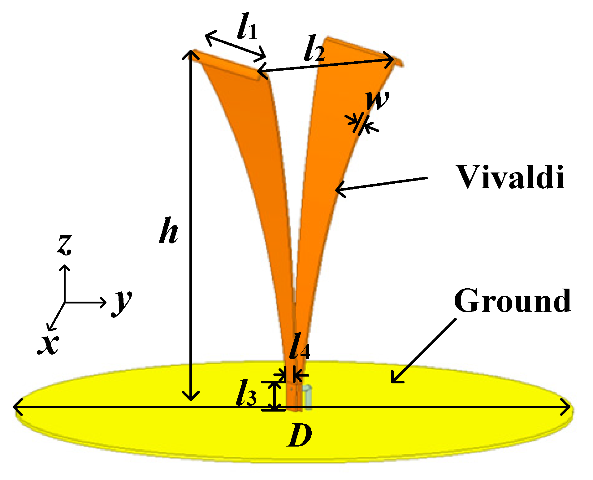
Figure 1. The structural model of the three-dimensional Vivaldi antenna.
Electronics 13 00914 g001
Figure 2. The S-parameter simulation result of the three-dimensional Vivaldi antenna.
Electronics 13 00914 g002
Figure 3. The longitudinal electric field distributions of the three-dimensional Vivaldi antenna.
Electronics 13 00914 g003
Figure 4. The structural model of the improved three-dimensional Vivaldi antenna.
Electronics 13 00914 g004
Figure 5. The S-parameter simulation results of the improved three-dimensional Vivaldi antenna.
Electronics 13 00914 g005
Figure 6. The longitudinal electric field distributions of the improved three-dimensional Vivaldi antenna.
Electronics 13 00914 g006
Figure 7. The design schematic diagram of electrically small Vivaldi antenna based on distributed passive network loading.
Electronics 13 00914 g007
Figure 8. The structural model of the electrically small Vivaldi antenna based on distributed passive network loading.
Electronics 13 00914 g008
Figure 9. The S-parameter simulation results of the electrically small Vivaldi antenna based on distributed passive network loading.
Electronics 13 00914 g009
Figure 10. The radiation pattern simulation results of the proposed electrically small Vivaldi antenna based on distributed passive network loading.
Electronics 13 00914 g010aElectronics 13 00914 g010b
Figure 11. The photograph of the proposed ultra-wideband electrically small antenna and the test scheme.
Electronics 13 00914 g011
Figure 12. The S-parameter measurement results of the proposed electrically small Vivaldi antenna based on distributed passive network loading.
Electronics 13 00914 g012
Figure 13. The radiation pattern measurement results of the proposed electrically small Vivaldi antenna based on distributed passive network loading.
Electronics 13 00914 g013aElectronics 13 00914 g013b
Table 1. The comparison of the proposed electrically small Vivaldi antenna with other works.
Ref.Bandwidth (GHz)Dimensions/λ03OctavePeak Gain (dBi)
[18]1–60.21 × 0.21 × 0.1163.6
[22]0.78–200.32 × 0.47 × 0.05225.67.4
[37]1.568–1.5830.068 × 0.068 × 0.0521.009−2.5
[39]3–5.250.5 × 0.5 × 0.41.75−1.5
This work0.2–30.06 × 0.05 × 0.12158.3
λ0 is the wavelength of the lowest frequency of the antenna.
Disclaimer/Publisher’s Note: The statements, opinions and data contained in all publications are solely those of the individual author(s) and contributor(s) and not of MDPI and/or the editor(s). MDPI and/or the editor(s) disclaim responsibility for any injury to people or property resulting from any ideas, methods, instructions or products referred to in the content.