Abstract
Bus and register management is one of the crucial aspects of application-specific integrated circuit-, system-on-chip-, or field-programmable gate array-based designs. The problems related to it are well known, and multiple tools or approaches are already trying to solve or mitigate them. However, all available solutions share the same register-centric paradigm. A user defines registers and then manually lays out the data into the registers. Such an approach has its limitations. A description does not contain information on data spanning multiple registers or data forming a broader context, for example, procedure arguments. It also does not contain information on the purpose of the data. As a result, the generated access code is low-level and usually needs an extra wrapper, which leaves room for potential human mistakes. For instance, it is the user’s responsibility to guarantee proper access order to registers or to provide an atomic change of data wider than a single register width. This article proposes a new approach, the functionality-centric approach. In the functionality-centric approach, the user defines the data with the type of their functionality. The registers and bus hierarchy are later implicitly inferred. By defining the functionality of the data placed in the registers, it is possible to generate more access code, increase code robustness, improve system design readability, and shorten the implementation process.
1. Introduction
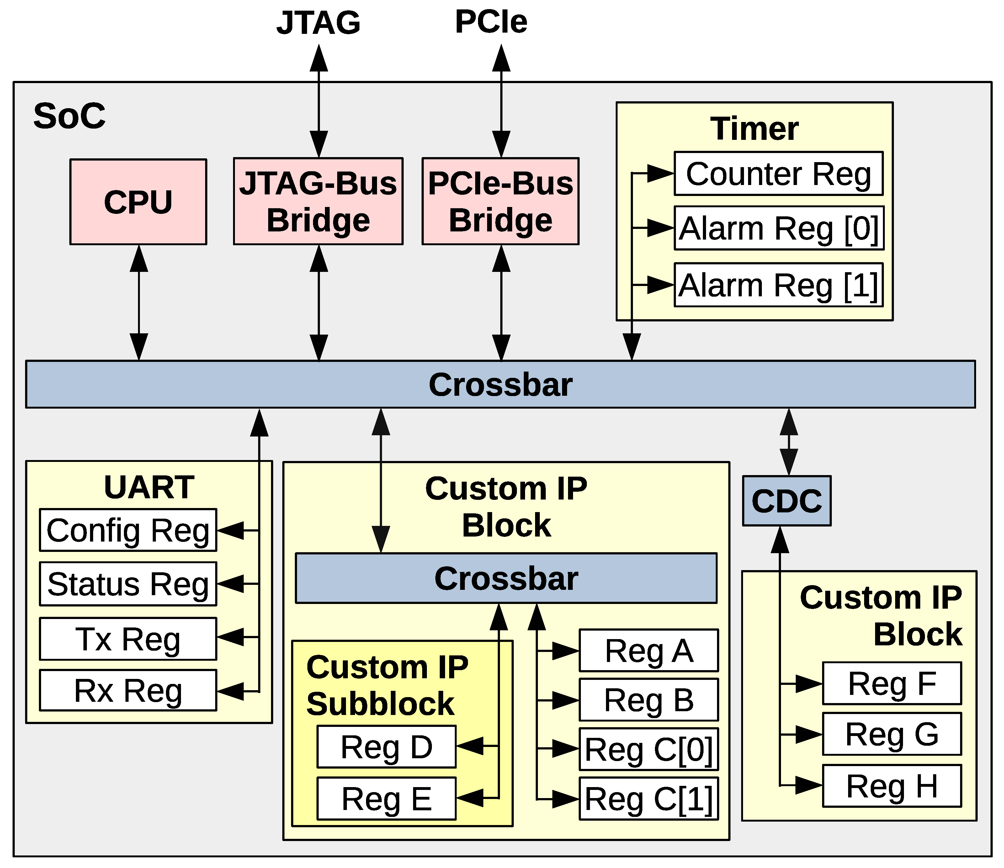
Modern ASIC, FPGA, or SoC-based designs have some kind of internal bus. Such a bus is often referred to as a “system bus”, “local bus”, “on-chip bus”, “interconnect bus”, or “on-chip interconnect bus” (the last one is the most formal and probably the most appropriate). The primary purpose of the bus is to provide an organized and structured manner for connecting individual modules within the chip. The secondary purpose is to be a gateway to access gateware/hardware design internals from the firmware/software stack. Such access includes reading status signals, writing control signals, procedure triggering, bidirectional data streaming, interrupt signaling, etc. Figure 1 presents an example of a simplified architecture of a SoC. Bus fabric components are in blue, slave modules are in yellow, and master modules are in red.
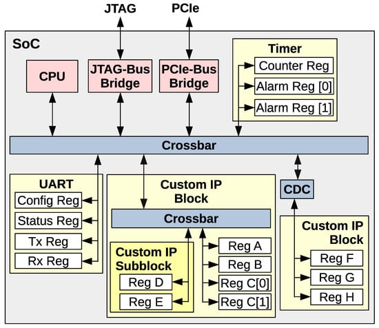
Figure 1.
Example architecture of a SoC design with an internal bus.
A bus usually consists of an address bus, a data bus, and a control bus. The most popular on-chip buses used in FPGA-based designs are probably Wishbone [1] and AXI [2] (which is part of the AMBA).
If a design contains an internal bus, then the bus needs to be managed. The bus management consists of the following logical tasks:
- Address space management. This includes:
- (a)
- Assigning address ranges to the modules.
- (b)
- Aligning address ranges according to the user’s policy.
- Bus fabric management. This includes:
- (a)
- A description of the modules’ hierarchy.
- (b)
- Generation of the bus fabric components (such as crossbars) according to the user-provided description.
- Registers’ management. This includes:
- (a)
- Ordering registers within the modules.
- (b)
- Splitting long signals between multiple registers.
- (c)
- Grouping short signals into a single register.
- (d)
- Attributing additional functions to the registers, such as associated strobe or acknowledgment signals.
All bus and register management tasks can be performed manually, semi-automated, or fully automated. The greater the automation level, the less room for potential engineers’ mistakes and the greater the pace of the project development.
Managing the bus in a complex system is a nontrivial and well-known problem, especially in hardware–software codesign projects [3,4,5,6,7,8]. Even though various approaches and implementations have already been proposed, there is still no solution that would fully automate the bus management process. All available standards and tools only support some of the logical elements of bus management or require users to do the register management manually. The register management is the most error-prone and time-consuming part of the bus management. What is more, when the register logic is not fully automatically generated, there is a need to verify the behavior of the registers. This is usually conducted in simulation by directed or randomized test benches, although [9] presents the benefits of doing register verification using formal methods, and [10] shows an example implementation of this idea.
The information about registers is utilized by software, hardware, and verification engineers. Typically, a specification of the registers is designed by the hardware designer or system architect. It changes multiple times during the design and implementation phases for different reasons, such as bugs, requirement changes, technical limitations, or user feedback. A simple change in a single register may imply adjustments in both hardware and software. These adjustments cost money and time.
Several formal and informal tools exist to address issues related to register management. However, they all share the same concept of describing registers at a very low level. That is, the user has to define the registers’ layout implicitly. For example, in the case of a register containing multiple statuses, it is the user’s responsibility to specify the bit position for every status. Such an approach is called by the author as the register-centric approach because the user defines registers and then manually lays out the data into the registers.
This paper proposes a new functionality-centric approach. In the functionality-centric approach, the user specifies the functionalities that must be provided by the data stored in the registers. The register layout is automatically generated based on the functional requirements. Such an approach increases the amount of automatically generated hardware description and software code and decreases the amount of code requiring manual implementation compared to the register-centric approach. Not only can the register masks, addresses, and single read and write functions be generated but also complete custom functions with optimized access methods. This, in turn, leads to shorter design iterations and fewer bugs.
The author has implemented a domain-specific language as a proof of the concept. The language is named Functional Bus Description Language (FBDL), and its specification is publicly available [11]. The FBDL bus description, as well as the functionality-centric approach concept is bus-type-agnostic. This implies that the actual bus type depends on the compiler support or, more precisely, on the generators provided by the compiler’s back-end. However, a single compiler might support multiple bus types (AMBA family, Avalon, Wishbone, etc.). The specification defines what access code must be generated for each functionality but does not enforce exactly how the generated API shall look. Such an approach has been chosen because different projects might have different requirements. For example, high-performance applications might require an asynchronous API, while a synchronous API might be sufficient for applications without hard timing constraints. The compiler front-end is available at [12], and the compiler back-end is available at [13]. The compiler back-end implemented as a proof of the concept currently supports only the Wishbone bus. In FBDL, the functionality is denoted as the type of the data. However, the description of the language and the compiler is not the goal of this paper. This article uses the implemented language to present the new approach and show examples comparing the register-centric and functionality-centric approaches. The language syntax is straightforward and intuitive, so the reader should be able to understand this article without having to read the specification first.
This article has numerous listings used as examples to better illustrate problems or explain solutions. The VHDL language has been chosen for the hardware description, and C or Python languages have been chosen for the firmware and software. However, all presented concepts are programming language-agnostic, so any language could be selected, and the reasoning would remain valid.
The structure of the paper is as follows: Section 2 is the prior art analysis. It includes only solutions following the register-centric paradigm. The author proposes a paradigm shift in the functionality, and no solution following this approach has been found. Section 3 compares two descriptions of the same system. One of the descriptions follows the register-centric approach, while the other follows the functionality-centric approach. The section contains multiple listings and waveforms presenting how the functionality-centric approach can decrease the probability of human mistakes and shorten the time required to implement the system. Section 4 briefly describes the synthesis results. Section 5 summarizes the advantages of using the functionality-centric approach compared to the register-centric approach. Section 6 outlines challenges and directions for future work.
2. State of Art
This section presents the current state of the art. The term “tool” is used for all solutions, although not all are strictly tools. Moreover, some are standalone entities, while others are a part of more extensive frameworks. Each tool has been implemented and designed by different teams. Although their main goal is the same, they sometimes accentuate diverse areas. As a result, relative comparison is not always straightforward. This is why they are rather matched against a generic template. Nonetheless, none of the available solutions offers a functional view of data placed in the registers. They are all register-centric.
The author found the following 15 tools addressing the bus and register management problem: airhdl [14], AGWB [15,16], AutoFPGA [17], Cheby [18,19], Corsair [20], hdl_registers [21], II (Internal Interface) [22], CII (Component Internal Interface) [23,24], IP-XACT [25], Opentitan [26,27], Register Wizard [28,29], RgGen [30], SystemRDL [31], VhdMMIO [32], and Wbgen2 [33]. Some FPGA tool vendors also try to address the problem (for example, Block Designer—AMD Xilinx, Platform Designer—Intel).
Register-centric approaches can be divided into two classes depending on the data they produce. The first class, as the output data, produces information on register addresses, bit shifts, and masks. The second class abstracts registers and bit fields as objects. The user does not explicitly use addresses, masks, and bit shifts but calls methods for reading and writing particular registers and bit fields. Instead of providing methods for reading and writing, some solutions prefer overloading operators, for example [34]. The second class is safer to use as it eliminates mistakes caused, for example, by applying a bit shift of bit field A to bit field B.
It is important to mention that all available tools and solutions are in continuous development, so some of their features might have changed, or new features might have been added since they were analyzed. It is also worth mentioning that if tool T claims support for a feature F or language L, then it might not be full support, as all such tools are implemented incrementally. It does not indicate the weakness of the tools but rather shows a pragmatic approach to the problem. There would be no technical progress in the described field if the tools were usable only when they were 100% complete.
Table 1 presents the result of the review of existing solutions. The comparison table also includes FBDL to satisfy the reader’s curiosity. Comparing bus and register management tool features is a challenging task. First of all, none of the register-centric tools, except SystemRDL, has a formal specification. The implementation is the specification. What is more, most of the tools target only a limited set of hardware description or programming languages, and they are usually tailored to these languages. Comparing features of FBDL with register-centric tools is also not straightforward, as FBDL is functionality-centric and has a different paradigm. For example, some of the tools allow data value range constraints. However, it works only for data fitting a single register, whereas in FBDL, it works for data of any width. Partial support means that a given feature is available only to some extent. For example, tools utilizing the YAML [35] format support parametrization achieved using the YAML syntax. However, they do not provide any extra parametrization mechanism, and a full design parametrization is not possible solely with YAML inheritance.

Table 1.
Comparison of some of the features of the bus and register management tools (Y—yes, N—no, DoC—depends on compiler, P—partial, U—unclear).
3. Advantages of Functionality-Centric Approach
This section presents two example descriptions of the same system. The first description uses the register-centric approach and utilizes the AGWB tool. The second description uses the functionality-centric approach and utilizes FBDL. The AGWB tool was chosen for the register-centric approach for two reasons. The first one is that AGWB belongs to the class of register-centric tools abstracting registers and bit fields as objects, which makes it safer than the register-centric class providing users with addresses, masks, and bit shifts. The second reason is that AGWB and FBDL use the same VHDL library for the Wishbone bus, making the analysis and comparison easier as bus-related signals share the same types.
Both descriptions have been functionally verified in cosimulations. The repository [36] contains the hardware descriptions and software code used for the cosimulations. It also contains all automatically generated files in the autogen directory so that readers do not have to install any application to view all relevant files. From the reader’s point of view, the most important files are tb_agwb.vhd, tb_fbdl.vhd, test_agwb.py, test_fbdl.py, and all files placed in the autogen directory. All remaining files are dependency or script files related to the build and run automation and are irrelevant to the analysis. All listings in Section 3 come from the repository.
Before any comparisons, the author would like to introduce the “advantage classes” term. The term is not formal but helps to classify the advantages of the functionality-centric approach over a register-centric approach. The advantage class is a characteristic of the quality of the work. There are four advantage classes listed below in alphabetical order:
- Maintainability (M) indicates how easy it is to modify the system behavior;
- Readability (R) denotes the ease of understanding the system;
- Safety (S) represents the probability of human mistakes;
- Time (T) represents the time required to implement, adjust, or correct the system.
Although the advantage classes are defined, the metrics for each class are not introduced. This is because the classes are a bit fuzzy, and it is impossible to introduce objective metrics that cannot be questioned. Users are assumed to evaluate solutions in terms of advantage classes based on their expert knowledge, experience, and common sense.
Titles of Section 3.1, Section 3.2, Section 3.3, Section 3.4 and Section 3.5 are suffixed with letters indicating which advantages classes are brought by the functionality-centric approach compared to the register-centric approach. Within subsections, the author justifies why the functionality-centric approach is advantageous compared to the register-centric approach. Although the author thinks most advantage classes should be assigned to all the presented advantages, only the most significant ones have been chosen.
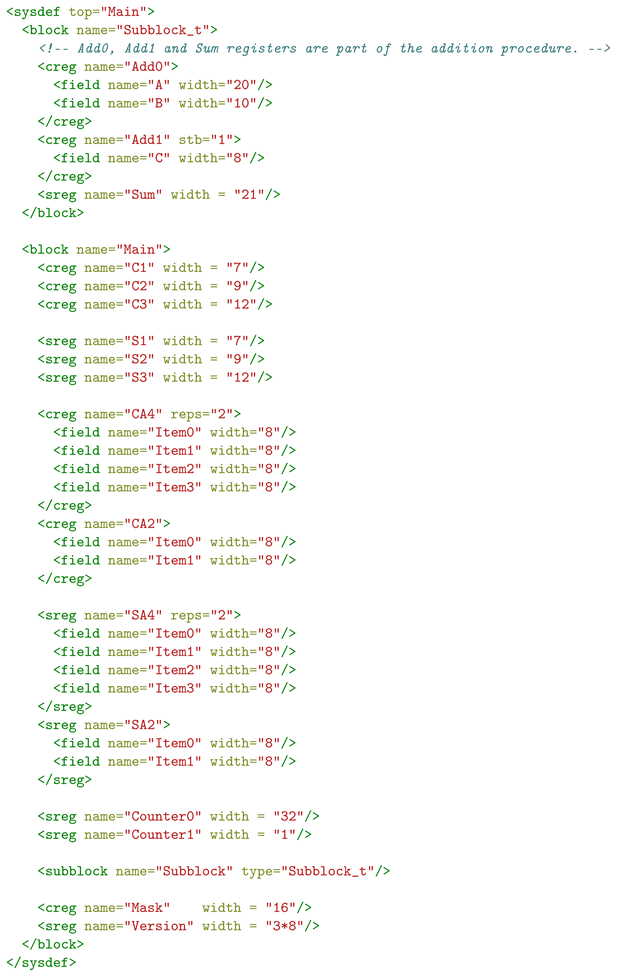
Listing 1 presents the example bus structure description in the register-centric AGWB format, and Listing 2 presents the description of the same bus structure in the functionality-centric FBDL format. The first noticeable difference is the verbosity of the register-centric description (53 lines vs. 23 lines). This is because AGWB is based on the XML format, and FBDL is a domain-specific language. However, a functionality-centric approach can also be based on any popular format, such as YAML, JSON, or XML.
| Listing 1. Example bus structure description in the register-centric AGWB format. |
 |
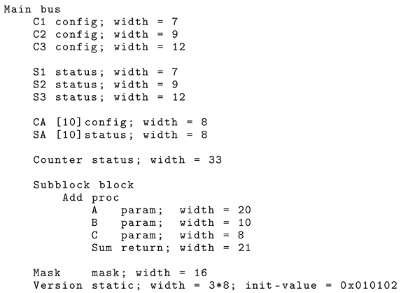
| Listing 2. Example bus structure description in the functionality-centric FBDL format. |
 |
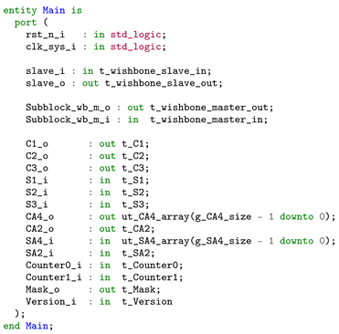
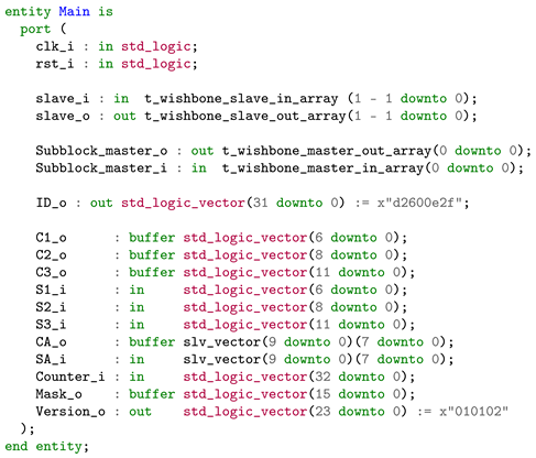
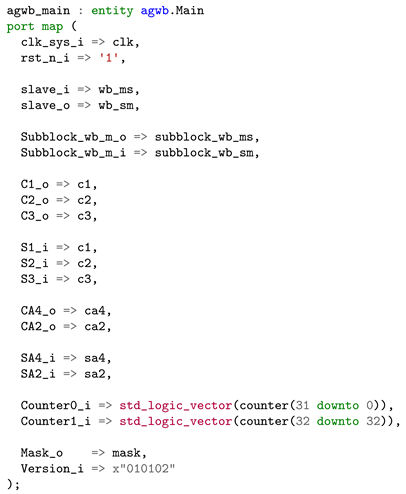
Listing 3 presents the VHDL entity interface of the Main block generated by the register-centric AGWB tool, and Listing 4 presents the VHDL entity interface of the Main block generated by the functionality-centric FBDL. AGWB defines custom subtypes for the ports. However, these subtypes are simple std_logic_vector types, which are irrelevant to the analysis. The most noticeable difference is that in the case of the register-centric approach, the user is provided with ports representing registers. However, in the case of the functionality-centric approach, the user is provided with ports representing data. In the example case, it is visible for CA and SA versus CA4, CA4, SA4, and SA2, as well as for Counter, which is 33-bit-wide and in the case of the register-centric approach, it must be divided into two registers manually, (Counter0 and Counter1).
| Listing 3. Interface of the Main VHDL entity generated by the register-centric AGWB. |
 |
| Listing 4. Interface of the Main VHDL entity generated by the functionality-centric FBDL. |
 |
3.1. Automatic Data Placement-MT
In Listings 1 and 2, C1, C2, and C3 represent control information, and S1, S2, and S3 represent status information. The first difference is that although they represent the same information, they are different entities. In the case of the register-centric approach, the information is represented as registers with proper types. In the case of the functionality-centric approach, the information is represented as data with proper types. The difference has significant implications. In the case of the register-centric approach, the user must decide in advance the placement of the data within registers. For example, in Listing 1, S1, S2, and S3 are placed in 3 separate registers. However, as S1, S2, and S3 are read-only, and their total width is less than 32 bits, they could also be placed in one or two registers. Moreover, they can be placed in the registers with C1, C2, and C3 or in a separate register. Even with just 6 pieces of data, there are multiple possible placements. In the case of the functionality-centric approach, the compiler is responsible for the data placement within the registers, which reduces development time.
Table 2 presents data placement results generated by the FBDL compiler. As can be seen, S2 has been placed in the same register as C2, and S3 has been placed in the same register as C3. The compiler has performed this automatically to minimize the required address space. S1 has been placed in the same register as the Version, which contains static data (data that are never modified).C1 has been placed in a separate register with address 6, and these are the only data placed in this register.
Table 2.
Data placement results for single control and status data.
Now, let us consider what happens if the system requirements change and the user needs to change the width of some data. For example, both C3 and S3 shall now be 2-bit-wide. In the case of the register-centric approach, the user must manually adjust the register layout. Depending on the scale of the change, it may be required to reshuffle the bit fields between registers. In the case of a width decrease, the data will still fit the registers. However, the generated address space size might not be optimal. In the case of a width increase, the data might no longer fit the register width, and the user must manually create additional registers. In the case of the functionality-centric approach, the data are automatically placed within the registers by the compiler, so the only change the user must introduce is the change in the value of the width property. Such an approach improves systems maintainability.
Table 3 presents data placement results generated by the FBDL compiler after changing the C3 and S3 width to 2. C2, S2, and S3 are now placed in the same register. Some addresses are changed because the compiler has found a better register layout, resulting in a smaller address space size. The whole recompilation process takes milliseconds as it is performed automatically by the computer program. Doing the same manually by the user would take seconds or even minutes for more complex adjustments.
Table 3.
Data placement results for single control and status data after the C3 and S3 width change.
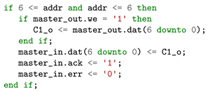
Listing 5 presents the VHDL description generated for C1 access by the register-centric AGWB, and Listing 6 presents the VHDL description generated for C1 access by the functionality-centric FBDL. The difference is minor and irrelevant. The snippets are syntactically different mainly because of the custom types used by AGWB. The access address also differs because AGWB and FBDL assign addresses to registers in different order. The description has the same semantics because the C1 width is less than the data bus width. However, the access description generated for the gateware/hardware and the access code generated for the firmware/software has significant differences between register-centric and functionality-centric approaches when the data are arrays, when the data are wider than the data bus, or when the data form a broader context, what is presented in the corresponding Section 3.2, Section 3.3 and Section 3.4.
| Listing 5. VHDL access description generated by the register-centric AGWB tool. |
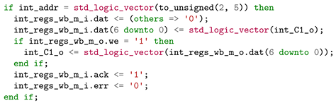 |
| Listing 6. VHDL access description generated by the functionality-centric FBDL. |
 |
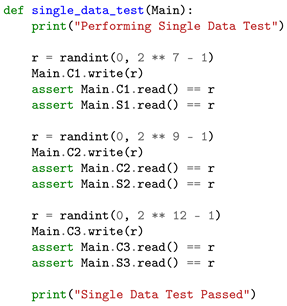
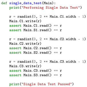
Listing 7 presents Python code for accessing single data in the register-centric approach, and Listing 8 presents Python code for accessing single data in the functionality-centric approach. Within test benches, C1, C2, and C3 are connected directly to S1, S2, and S3 to form a feedback loop in the hardware description. There is almost no difference in the software access code, except classes generated by the FBDL have additional attributes with the data width. However, the access code generated for the firmware/software has a significant difference between register-centric and functionality-centric approaches when the data are wider than the data bus, which is presented in Section 3.3.
| Listing 7. Python code for testing access to single data in the register-centric approach. |
 |
| Listing 8. Python code for testing access to single data in the functionality-centric approach. |
 |
3.2. Automatic Array Handling—MRT
In Listing 2, CA denotes an array of control data, and SA denotes an array of status data. Listing 1 represents the same data as CA4, CA2, SA4, and SA2 registers. Within test benches, the CA array is connected directly to the SA array to form a feedback loop in the hardware description.
The first difference is that in the case of the register-centric approach, the user must manually lay out array data in the registers. In the case of the functionality-centric approach, it is the compiler’s responsibility. The same difference was presented in Section 3.1 for single data. However, the manual placement task is even more time-consuming in the case of array data. Depending on the data width and item count, the array might be represented as a replication of a single register or require an extra register containing a different number of items. The latter is in the example description, where 10 items of width 8 are placed within 3 registers with a 4, 4, and 2 distribution. Moreover, not all register-centric tools allow bit-field replication within a register. The user must define each bit field separately within the register. For example, in the case of a 32-element array with a 1-bit data width, the user must explicitly define 32 bit fields.
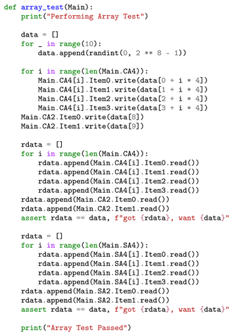
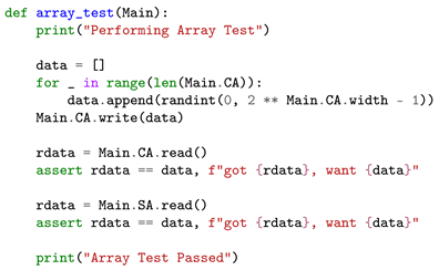
The second significant difference between the register-centric and functionality-centric approaches regarding array handling is the generated firmware/software access code. Listing 9 presents Python code for accessing the array data in the register-centric approach, and Listing 10 presents Python code for accessing the array data in the functionality-centric approach. In the register-centric approach, the user must know the relationship between the data index and register and the bit-field index. In other words, if the user wants to access data with index D, they must explicitly code access to the register with index R and the bit field with index F. In the case of the functionality-centric approach, the user operates on the array data, and all the index mapping is handled automatically by the code generated by the compiler.
| Listing 9. Python code for testing access to array data in the register-centric approach. |
 |
| Listing 10. Python code for testing access to array data in the functionality-centric approach. |
 |
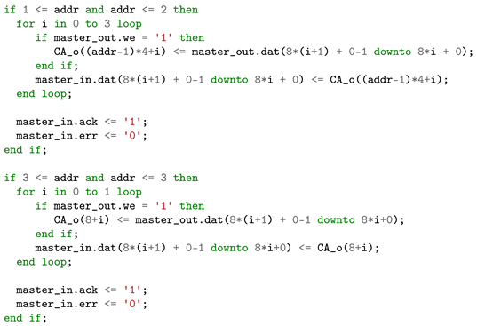
A functionality-centric compiler shall be able to handle arrays with a single element of any width. Listing 11 presents the VHDL access description generated for the CA array by the functionality-centric FBDL. As can be seen, 4 elements are placed in the register with address 1, another 4 elements are placed in the register with address 2, and the remaining 2 are placed in the register with address 3.
| Listing 11. CA (size = 10, width = 8) array VHDL access description generated by the functionality-centric FBDL. |
 |
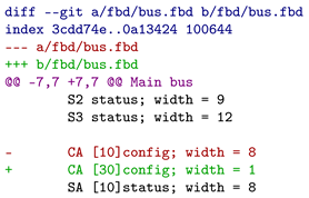
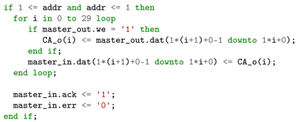
Let us suppose that system requirements have changed, and CA shall now be an array of 30 elements with a width equal to 1 bit. Listing 12 presents the adjustment that has to be applied to the bus description, and Listing 13 presents the VHDL access description generated for the new CA declaration. As can be seen, all the elements are now placed within a single register with address 1.
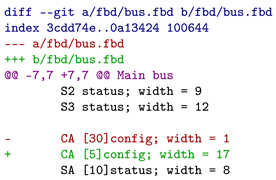
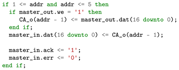
Let us suppose that system requirements have changed again, and CA shall now be an array of 5 elements with a width equal to 17 bits. Listing 14 presents the adjustment that has to be applied to the bus description, and Listing 15 presents the VHDL access description generated for the new CA declaration. As can be seen, each item is now placed in a separate register and spans bits from 0 to 16. The first array register has address 1, and the last one has address 5.
| Listing 12. Functionality-centric description diff for CA size change to 30 and width change to 1. |
 |
| Listing 13. CA (size = 30, width = 1) array VHDL access description generated by the functionality-centric FBDL. |
 |
| Listing 14. Functionality-centric description diff for CA size change to 5 and width change to 17. |
 |
| Listing 15. CA (size = 5, width = 17) array VHDL access description generated by the functionality-centric FBDL. |
 |
A functionality-centric compiler shall also handle access to arrays with elements wider than the data bus. Such an example is not presented as access atomicity is described in detail in Section 3.3.
3.3. Access Atomicity—MST
In Listings 1 and 2, Counter represents status data that are wider than the bus width. In the functionality-centric approach, each instantiated functionality has a bit width independent of the data bus width. In register-centric approaches (CII being the exception), the designer explicitly puts data into the registers. Hence, it cannot be defined as wider than the single register width. For data wider than the register width, the user must define multiple registers and partition the data into the registers. However, when the access to the data must be atomic, two additional issues arise:
- Atomic data value change must be manually implemented in the HDL.
- Correct access order to the registers must be manually implemented in the firmware/software. The data are updated on writing the last register in the case of data writes and latched on reading the first register in the case of data reads. Incorrect access order results in an invalid value if data change during the transaction.
In the functionality-centric approach, the compiler automatically handles the additional issues related to access atomicity, as data are treated as an indivisible whole, not as a fragmented piece.
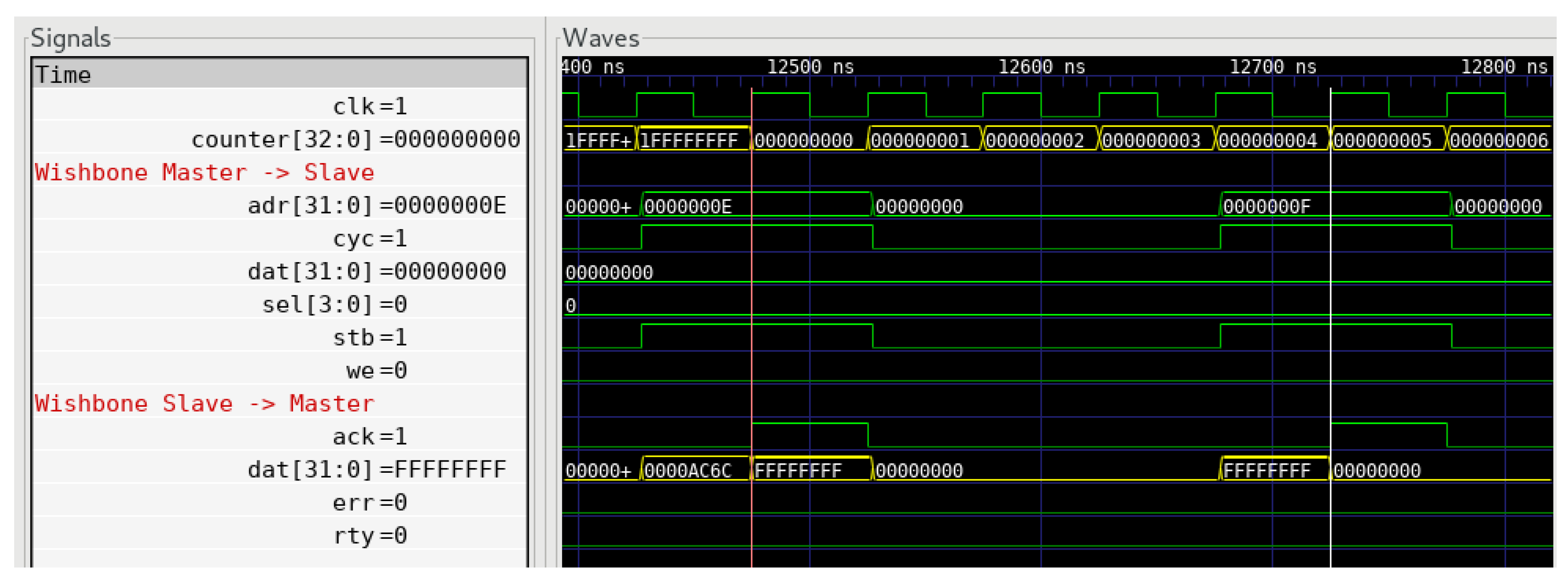
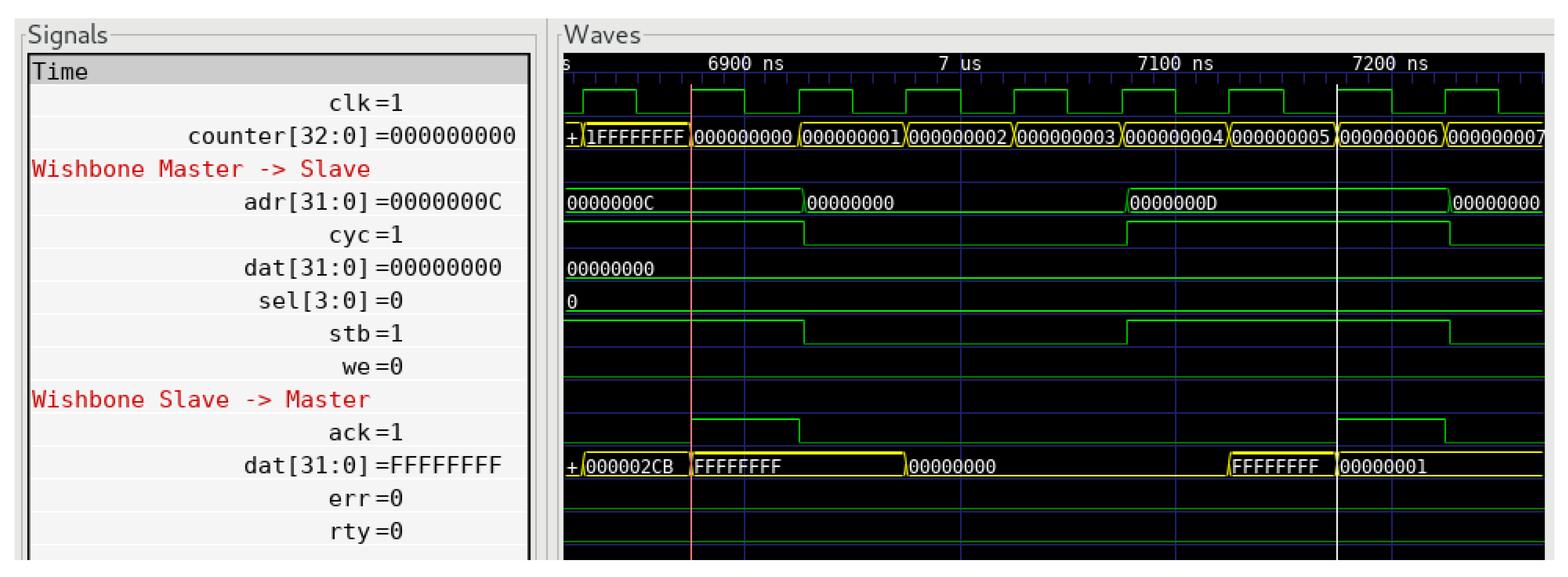
Figure 2 presents waveforms, and Listing 16 presents the generated VHDL description for Counter access in the register-centric approach. Counter registers’ sampling times are marked with markers. During the first register read, the counter value equals 0x1FFFFFFFF,and the value on the data bus equals 0xFFFFFFFF. This is the expected value. Before the second read, the counter overflows. During the second read, the counter value equals 0x000000004,and the value on the data bus equals 0x00000000. The read value of the bit with index 33 is incorrect because during the first read, it equaled “1”, but it equaled “0” during the second read. The final Counter read value equals 0x0FFFFFFFF instead of 0x1FFFFFFFF. This is two times less than expected. The problem occurs not only when values overflow but also when there is a change in the middle bits of a signal wider than the data bus. For example, if Counter were 65-bit-wide, the same problem with bit 33 would occur even though Counter did not overflow.
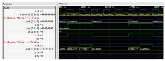
Figure 2.
Counter nonatomic access issues in register-centric approach.
| Listing 16. Counter VHDL access description generated by the register-centric AGWB. |
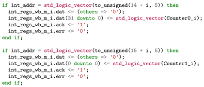 |
Figure 3 presents waveforms, and Listing 17 presents the generated VHDL description for the Counter access in the functionality-centric approach. Counter registers’ sampling times are marked with markers. During the first register read, the counter value equals 0x1FFFFFFFF, and the value on the data bus equals 0xFFFFFFFF. This is the expected value. Before the second read, the counter overflows. During the second read, the counter value equals 0x000000005. However, the value on the data bus equals 0x00000001. The read value of the bit with index 33 equals “1”, because this was the bit’s value when the first register read occurred. Compared to the register-centric approach, in the functionality-centric approach, the user is provided with the data, not the registers, and it is the compiler’s responsibility to guarantee atomic data access.
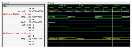
Figure 3.
Counter atomic access in functionality-centric approach.
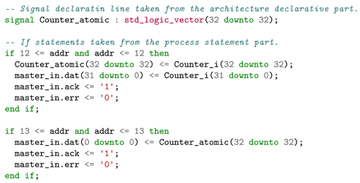
The generated VHDL access description has an additional Counter_atomic signal latching the value of the remaining Counter bits when the read of the first register storing the Counter value happens. Such a register is often called a snapshot or shadow register, although to the author’s knowledge, there is no formal definition. When reading the upper bit, the data bus is driven from the snapshot register, not the Counter register.
| Listing 17. Counter VHDL access description generated by the functionality-centric FBDL. |
 |
In the register-centric approach, the user can provide access atomicity the same way. However, it must be done manually outside the automatically generated bus fabric description. This requires extra time and introduces room for potential mistakes, for example, when the user accidentally connects the wrong bits to the snapshot register. It is also required that the first read register has an associated read acknowledgment signal that triggers the snapshot register data latch.
Providing access atomicity consumes extra resources, and not all data wider than the data bus require atomic access. In such a case, the functionality-centric compiler can be informed to discard access atomicity for particular data. For instance, in the case of FBDL, the user can set the atomic property to false (atomic = false).
3.4. Procedure and Stream Contexts—MRS
In Listing 1, registers Add0, Add1, and Sum represent a procedure. The procedure is a simple addition procedure with three summands: A, B, and C. The Sum register stores the operation result.
Describing procedures in the register-centric approach has the following drawbacks:
- The user must manually place the parameter and return data in the registers. In the case of procedure data, atomic access is not required as all the argument data are latched using an additional strobe signal. Usually, the strobe pulse is generated when the last register storing procedures’ argument is written. No atomicity requirement means the argument data can be packed tightly into the registers to minimize the required address space. The bits of single data can be split into two registers even if the data width is less than the data bus width. In the case of Listing 1, 2 bits of C could be placed in the register Add0, and only the remaining 6 bits could be placed in the register Add1. This would not change the number of required registers in the example addition procedure. However, such an approach can reduce the number of required registers in the case of procedures with more parameters. Moreover, if there is enough space in the parameters’ last register, the return data can be placed there. However, not all register-centric tools allow placing control and status data in the same register. In the case of a procedure data change, the register-centric approach might require manual and time-consuming data reshuffling between registers.
- Without any additional comment, a user can only guess based on the register names that particular registers form a procedure context. Even with a comment, it may not be up to date, as it must be manually synced.
- The user must provide correct parameter registers’ write order and return registers’ read order in firmware/software.
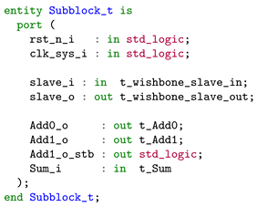
Listing 18 presents the interface of the Subblock VHDL entity generated by the register-centric AGWB tool. The user is provided with the addition procedure registers directly. There is no encapsulation of the procedure context.
| Listing 18. Counter Interface of the Subblock VHDL entity generated by AGWB. |
 |
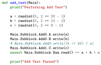
Listing 19 presents Python code for testing the addition procedure in the cosimulation test bench. The A and B bit fields are written separately, meaning the register Add0 is written twice. This can be avoided. However, it is the user’s responsibility to create a valid value for the Add0 register write. The single Add0 write approach line is commented out.
| Listing 19. Python code for testing the addition procedure in the register-centric approach. |
 |
The same addition procedure is presented in Listing 2. The functionality-centric procedure description is free of all the register-centric drawbacks. This is because the procedure context is defined explicitly using the proc functionality. Parameters and returns have their widths, but it is the compiler’s responsibility to place them in registers. The compiler is also responsible for generating the firmware/software method for calling the procedure, so there is no room for the incorrect access order mistake.
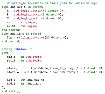
Listing 20 presents the interface of the Subblock VHDL entity generated by the functionality-centric FBDL. The procedure-related signals are encapsulated as record types. The call signal is driven high for one clock cycle every time the last parameter register is written. The exitt (exit is a VHDL keyword) signal is driven high for one clock cycle every time the last return register is read. In the example system, the exitt signal is ignored, and the call signal is used to trigger the add procedure. The Sum is updated every time the call signal equals “1”.
| Listing 20. Interface of the Subblock VHDL entity generated by the FBDL. |
 |
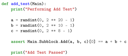
Listing 21 presents Python code for testing the addition procedure in the cosimulation test bench. In the functionality-centric approach, a user is provided with a function that can be explicitly called. There is no need to write parameter registers manually to call the procedure.
| Listing 21. Python code for testing the addition procedure in the functionality-centric approach. |
 |
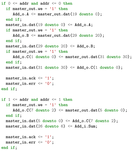
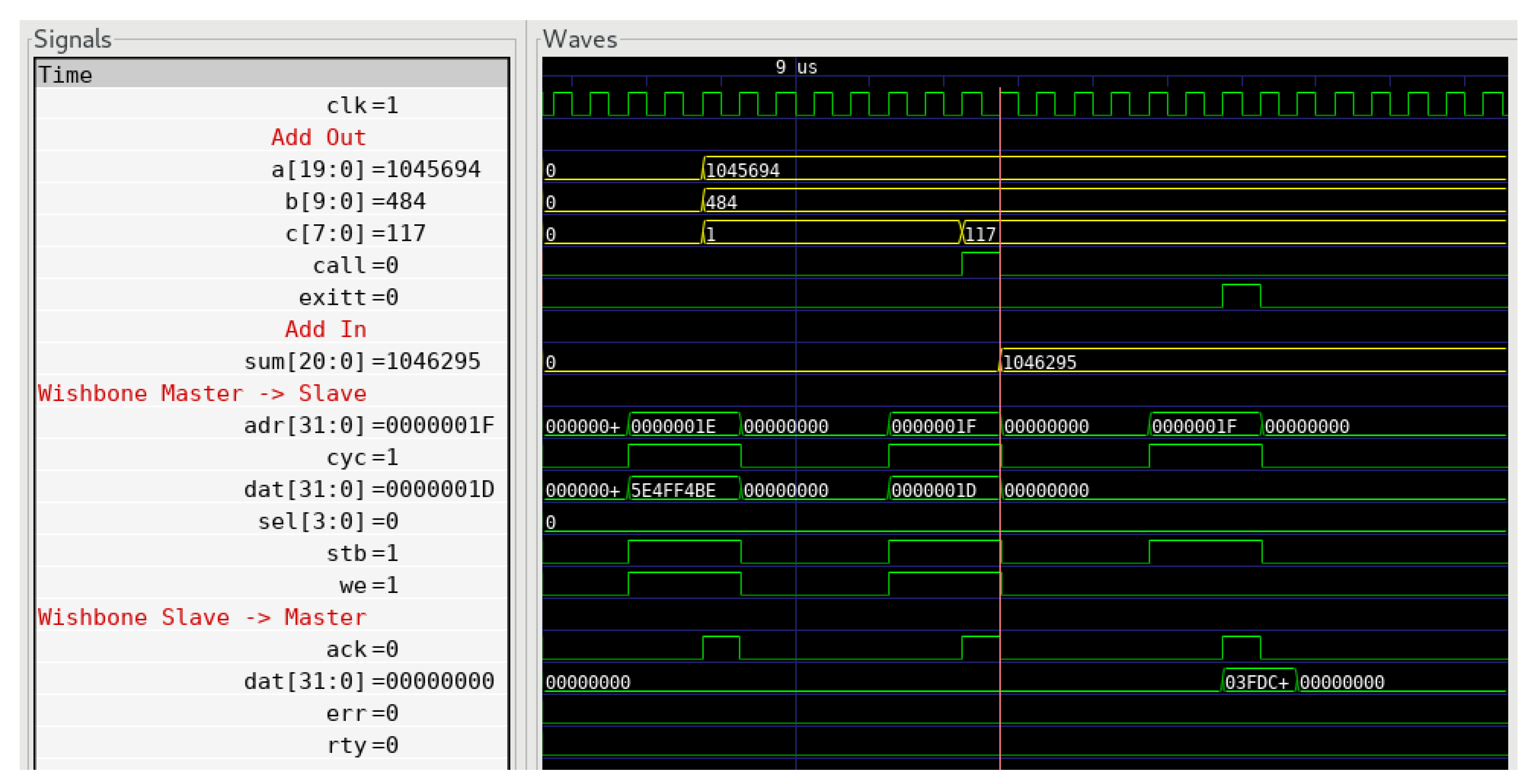
Listing 22 presents the add procedure access description generated by the functionality-centric FBDL. The address signal (addr) is a relative subblock address, hence low address values such as 0 and 1. The compiler automatically put the lower 2 bits of the C parameter in the same register as the A and B parameters. The compiler also put the return Sum in the same register as the upper 6 bits of the C parameter. Figure 4 presents waveforms for the add procedure test. There are 3 bus transactions, 2 writes, and 1 read. The second write access has the same address as the read access. Yellow waveforms have decimal formatting. The result of the procedure is correct (1,045,694 + 484 + 117 = 1,046,295). It also may be noticed that the value of the C parameter changes twice on both writes.
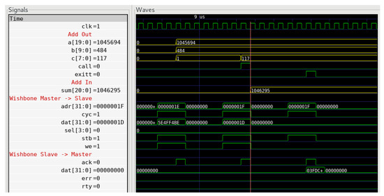
Figure 4.
Add procedure waveforms for a test bench utilizing the description generated by the FBDL.
| Listing 22. Add procedure access description generated by the functionality-centric FBDL. |
 |
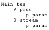
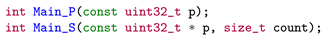
In a practical design, registers often form not only procedure contexts but also stream contexts. A stream is very similar to a procedure. The first difference is that a stream is always unidirectional. It always has only parameters (downstream) or only returns (upstream). The second difference is in the way firmware/software calls a stream. An access to a stream is multiple, and an access to a procedure is single. For example, Listing 23 presents a bus description containing a procedure and a stream. The code generated for the firmware, implemented in the C language, might include function prototypes presented in Listing 24. Distinguishing procedures and streams in the functionality-centric approach allows for more code generation.
| Listing 23. Example bus description containing a procedure and a stream. |
 |
| Listing 24. Difference between procedure and stream function prototypes. |
 |
The procedure example is contained within the subblock, both in the register-centric and functionality-centric approach. The goal is to present that in both approaches; describing the hierarchy of the modules is possible and is very similar and straightforward. The subblock functionality also allows a definition of the number of masters connected to the subblock via the masters property, which allows connections among multiple buses or physical interfaces. The additional interfaces can be connected directly or via a custom bridge if a protocol translation is required.
3.5. Additional Types—R
In the register-centric approach, a user declares the register type. Most available tools offer control registers and status registers. A control register can be read and written from the firmware/software and read (sometimes also written) from the gateware/hardware. A status register can be read from the firmware/software and read and written from the gateware/hardware. vhdMMIO is slightly different in this regard, as it has the concept of register behavior. The register behavior is an extension of the register type. However, this is still the register type, not the data type.
In the functionality-centric approach, a user declares the type of the data, not the register. This, in turn, allows the user to introduce additional types, increasing the amount of code that can be automatically generated and improving the system’s readability.
In Listing 1, there is a control register named Mask and a status register named Version. Mask is a bit mask, meaning the user will want to set, clear, and toggle particular bits of the value. Version represents static information that never changes. However, in the register-centric approach, the user can only guess based on the names that Mask is a bit mask and Version is static. The description could have extra documentation comments explaining the purpose of the registers, but it would have to be manually kept up to date.
In Listing 2, the same Mask and Static registers have distinct types. Based on the type, it is not only clear what functionality is served by the data, but it is also possible to generate access code functions for firmware/software with the desired programming interface. In the case of the static Version register, it is also possible to assign a value where the static data are declared, which improves readability. In most register-centric tools, the user has to check the gateware/hardware description to realize that the status register value never changes because some constant signal is assigned to the port. This is shown in Listing 25, which presents an instantiation of the Main entity generated by AGWB.
| Listing 25. Instantiation of the Main VHDL entity generated by the register-centric AGWB tool. |
 |
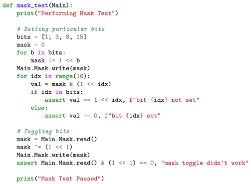
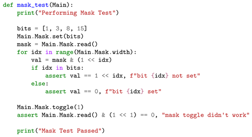
Listing 26 presents Python code for testing access to the Mask data in the register-centric cosimulation test bench, and Listing 27 presents Python code for the same test in the functionality-centric approach. In the case of the functionality-centric approach, it is possible to generate access methods operating directly on bits, which saves time and reduces the probability of human mistakes. In the case of the register-centric approach, it is impossible, as the compiler does not know the type of data stored in the control register.
| Listing 26. Python code for testing access to mask data in the register-centric approach. |
 |
| Listing 27. Python code for testing access to mask data in the functionality-centric approach. |
 |
4. Synthesis
Hardware descriptions generated by the register-centric AGWB and the functionality-centric FBDL approaches were synthesized to compare resource utilization and show that the functionality-centric approach is not only a theoretical concept but also something that works in practice. Vivado 2021.2 was used as the synthesis tool. The Synthesis Strategy was set to Default, and the -flatten_hierarchy property was set to none. The target part was xc7s25ftgb196-1Q (Spartan 7).
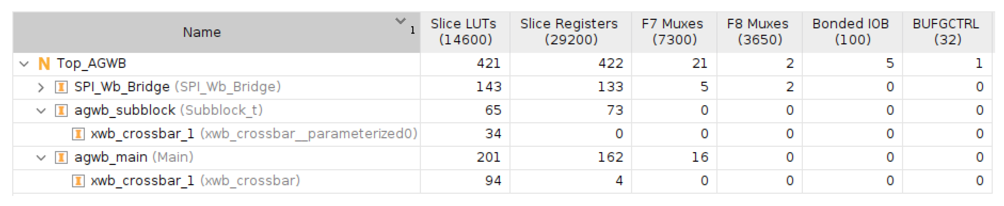
Figure 5 and Figure 6 present postsynthesis resource utilization for the register-centric AGWB and functionality-centric FBDL tools. Table 4 presents the same information but in a more straightforward comparison format.
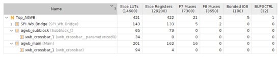
Figure 5.
Post–synthesis resource utilization for the register-centric AGWB tool.
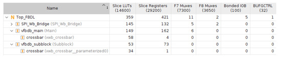
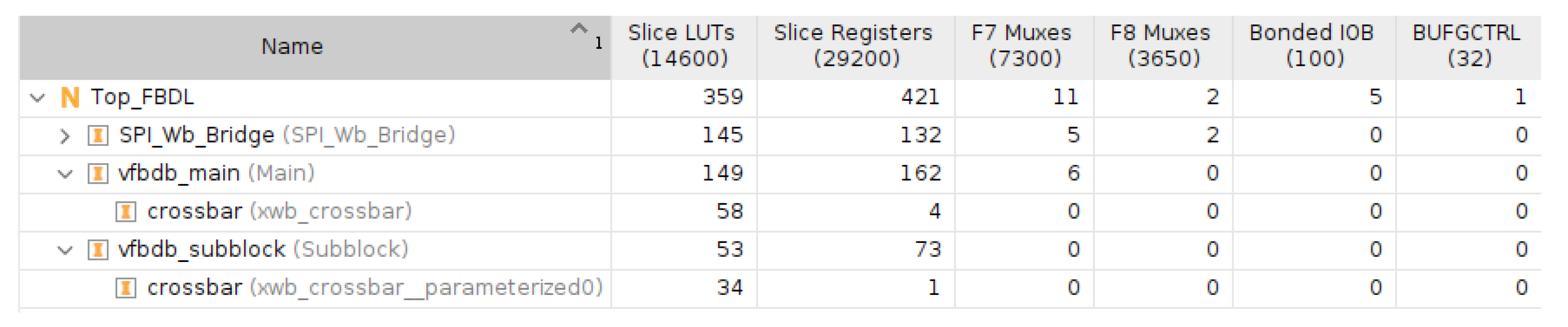
Figure 6.
Post–synthesis resource utilization for the functionality-centric FBDL.
Table 4.
Postsynthesis resource utilization.
The number of utilized registers was the same for AGWB and FBDL. This was expected as the number of required registers depends on the total number of data bits, and both approaches describe the same data, but use different approaches. The number of utilized registers was higher than the number of data bits because some registers were utilized for the bus logic. However, as the same bus and VHDL library were used in both examples, the number of registers utilized by the bus logic was the same.
The number of utilized LUTs was higher for the register-centric AGWB tool. In the case of the functionality-centric FBDL, the compiler automatically optimized the required address space size, resulting in simpler address decoding logic.
5. Summary
Describing a system bus using the functionality-centric approach offers the following advantages compared to the typical register-centric approach:
- A shorter development time, as more hardware description and software code can be automatically generated.
- A more readable and maintainable project structure. As the functionality-centric approach is more strongly typed than the typical register-centric approach, the description contains more information about the system. There is no need to read hardware description or software code to know that a particular set of registers form a broader context and are dependent (procedures and streams).
- Less probability of nonatomic data access bugs. In the functionality-centric approach, access to any piece of data is atomic by default. Nonatomicity is an opt-out feature achieved with an explicit action required from the user.
- No space for invalid access order bugs. Code for writing parameters or reading returns of procedures and streams is automatically generated so the register with the associated strobe or acknowledgment signal is always accessed last.
- Uniform data access interface across different target languages. As the functionality-centric approach is focused on the data functionality, it is easier to specify what kind of accesses must be generated for particular functionalities. This eliminates scenarios where the generated C code provides information on addresses, masks, and shifts, but, for example, the generated Python or C++ code abstracts this information by providing direct operations on registers and bit fields. The abstraction level of the code generated by a functionality-centric compiler can be the same regardless of the target language and is always at the functionality level.
The functionality-centric approach may also be used for on-chip connections utilizing the network-on-chip (NoC) technology [37,38,39,40]. As each network node has to distribute data within its borders, the traditional bus architectures are still used for this purpose. In such a design, the functionality-centric approach may be used to describe the functionality of particular buses of nodes. The routing algorithm and access interfaces are then implemented independently and are only hooked to the code generated by the compiler.
6. Challenges
Although the proposed functionality-centric approach for bus and register management has clear advantages compared to the traditional register-centric approach, some challenges still have to be addressed.
6.1. Functionality Types
The first challenge is the identification of potentially useful functionality types. For example, the FBDL compiler currently supports the following 13 functionalities: blackbox, block, bus, config, irq, mask, memory, param, proc, return, static, status, and stream. Not all functionalities bring something new compared to the register-centric approach. For example, the block functionality is used solely to describe the bus module hierarchy. The memory functionality is used for mapping external memories into the generated address space. Both block and memory serve the same purpose in the register-centric approach. The functionality-centric approach idea is still fresh, and maybe more helpful functionalities will be identified.
6.2. Data Grouping
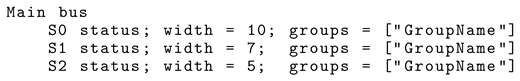
In the register-centric approach, the user can manually group data so that multiple data can be written or read using a single write or read transaction. This is usually achieved by putting multiple data in a single register as separate bit fields. The FBDL compiler solves the data-grouping issue by allowing the user to set the groups property. Listing Section 6.2 presents an example of data grouping in the functionality-centric approach. Such a description forces the compiler to put S0, S1, and S2 in the same register and to generate access code allowing for the reading of the whole group, not just individual elements. Whether grouping data in the functionality-centric approach using the additional groups property is the best way is still being determined.
| Listing 28. Example of data grouping in the functionality-centric FBDL format. |
 |
Nevertheless, entirely relying on the functionality-centric compiler’s grouping algorithm still may have disadvantages. Firstly, the compiler results might not always be optimal, for example, due to algorithm shortcomings. Secondly, automatic data grouping is not easy because of multiple constraints (described in Section 6.3), so the algorithm might have bugs for some corner cases. There should be a way to bypass the automatic data placement in the registers to mitigate potential downsides. For example, the FBDL compiler has the blackbox functionality dedicated to this purpose. The blackbox functionality allows the incorporation of blocks implemented manually or generated by external tools, for example, register-centric ones.
6.3. Registerification
The registerification is the process of placing data with functionality types into the registers. The process includes assigning data bit masks, register addresses, and block addresses. The term is new in the field and is coined in this article.
The optimal registerification algorithm takes work to achieve. Not only must the generated address space size be minimized but also the data access times. The registerification result must be deterministic and repeatable. From the user perspective, it is unacceptable that a system with the same description performs differently depending on the compiler run. There are also multiple constraints. For example, not-grouped control data cannot be put in the same register as this would imply a read–modify–write transaction. Data potentially accessed by the DMA engine (for example, arrays or multiregister atomic data) must be placed into registers with continuous addresses. Register storing procedure arguments and triggering the procedure cannot have any control data not belonging to the procedure as this data write would spuriously call the procedure.
In the current FBDL implementation, the registerification algorithm is based on the author’s experience and empirical knowledge. However, in the next step, the author wants to describe the problem formally and use state-of-the-art solvers.
Funding
This research received no external funding.
Data Availability Statement
The data presented in this study are available in this article.
Acknowledgments
The APC was supported by the Warsaw University of Technology.
Conflicts of Interest
The author declares no conflict of interest.
Abbreviations
The following abbreviations are used in this manuscript:
| ASIC | Application-specific integrated circuit |
| SoC | System-on-chip |
| FPGA | Field-programmable gate array |
| FBDL | Functional Bus Description Language |
| LUT | Lookup table |
| NoC | Network-on-chip |
References
- OpenCores. WISHBONE System-on-Chip (SoC)Interconnection Architecturefor Portable IP Cores. Available online: https://cdn.opencores.org/downloads/wbspec_b4.pdf (accessed on 3 June 2021).
- ARM. AMBA AXI and ACE Protocol Specification. Available online: https://developer.arm.com/documentation/ihi0022/latest/ (accessed on 3 June 2021).
- De Michell, G.; Gupta, R. Hardware/software co-design. Proc. IEEE 1997, 85, 349–365. [Google Scholar] [CrossRef]
- Jerraya, A.; Wolf, W. Hardware/software interface codesign for embedded systems. Computer 2005, 38, 63–69. [Google Scholar] [CrossRef]
- Takalo, J.; Kääriäinen, J.; Parviainen, P.; Ihme, T. Challenges of Software-Hardware Co-Design; VTT Working Papers 91; VTT Technical Research Centre of Finland: Espoo, Finland, 2008; p. 49. [Google Scholar]
- Kokila, J.; Ramasubramanian, N.; Indrajeet, S. A Survey of Hardware and Software Co-design Issues for System on Chip Design. In Advanced Computing and Communication Technologies; Choudhary, R.K., Mandal, J.K., Auluck, N., Nagarajaram, H.A., Eds.; Springer: Singapore, 2016; pp. 41–49. [Google Scholar]
- Ganesh, R. Design Issues in Hardware/Software Co-Design. Int. J. Res. Electron. Commun. Technol. 2020, 2, 1–5. [Google Scholar]
- Zulberti, L.; Di Matteo, S.; Nannipieri, P.; Saponara, S.; Fanucci, L. A Script-Based Cycle-True Verification Framework to Speed-Up Hardware and Software Co-Design: Performance Evaluation on ECC Accelerator Use-Case. Electronics 2022, 11, 3704. [Google Scholar] [CrossRef]
- Kim, N.; Park, J.; Min, B.; Park, W. Register Verification: Do We Have Reliable Specification? In Proceedings of the Design and Verification Conference and Exhibition, Grenoble, France, 18–22 March 2013. [Google Scholar]
- Saafan, H.; El-Kharashi, M.W.; Salem, A. Formal Based Methodology for Inferring Memory Mapped Registers. In Proceedings of the 2016 17th International Workshop on Microprocessor and SOC Test and Verification (MTV), Austin, TX, USA, 12–13 December 2016; pp. 15–18. [Google Scholar] [CrossRef]
- Kruszewski, M. FBDL Specification. Available online: https://github.com/Functional-Bus-Description-Language/Specification (accessed on 18 February 2023).
- Kruszewski, M. Go-fbdl-Functional Bus Description Language Compiler Front-End. Available online: https://github.com/Functional-Bus-Description-Language/go-fbdl (accessed on 18 February 2023).
- Kruszewski, M. Go-vfbdb-Versatile Functional Bus Description Language Compiler Back-End. Available online: https://github.com/Functional-Bus-Description-Language/go-vfbdb (accessed on 18 February 2023).
- Noasic GmbH. Airhdl. Available online: https://airhdl.com/#/ (accessed on 18 February 2023).
- Zabołotny, W.M.; Gumiński, M.; Kruszewski, M.; Müller, W.F. Control and Diagnostics System Generator for Complex FPGA-Based Measurement Systems. Sensors 2021, 21, 7378. [Google Scholar] [CrossRef] [PubMed]
- Zabołotny, W.M. Address Generator for Wishbone. Available online: https://github.com/wzab/agwb (accessed on 20 February 2023).
- Gisselquist, D. AutoFPGA. Available online: https://github.com/ZipCPU/autofpga (accessed on 21 February 2023).
- Plutecki, P.; Bielawski, B.P.; Butterworth, A. Code Generation Tools and Editor for Memory Maps. In Proceedings of the 17th International Conference on Accelerator and Large Experimental Physics Control Systems, New York, NY, USA, 5–11 October 2020; JACoW Publishing: Geneva, Switzerland, 2020. ISBN 9783954502097. [Google Scholar] [CrossRef]
- Cheby. Available online: https://gitlab.cern.ch/be-cem-edl/common/cheby (accessed on 22 February 2023).
- Bolnov, E. Corsair. Available online: https://github.com/esynr3z/corsair (accessed on 24 February 2023).
- Vik, L. hdl_registers: An Open-Source HDL Register Generator Fast Enough to Run in Real Time. Available online: https://hdl-registers.com/index.html (accessed on 17 February 2023).
- Pozniak, K.T. I/O Communication with FPGA Circuits and Hardware Description Standard for Applications in HEP and FEL Electronics. Available online: https://bib-pubdb1.desy.de/record/408703 (accessed on 17 February 2023).
- Drabik, P.; Pozniak, K.T. Maintaining complex and distributed measurement systems with component internal interface framework. In Photonics Applications in Astronomy, Communications, Industry, and High-Energy Physics Experiments; Romaniuk, R.S., Kulpa, K.S., Eds.; SPIE: Wilga, Poland, 2009; Volume 7502, p. 75022C. [Google Scholar] [CrossRef]
- Zagoździńska, A.; Poźniak, K.T.; Drabik, P.K. Selected issues of the universal communication environment implementation for CII standard. In Photonics Applications in Astronomy, Communications, Industry, and High-Energy Physics Experiments 2011; SPIE: Wilga, Poland, 2011; p. 80080N. [Google Scholar] [CrossRef]
- 1685-2014-IEEE Standard for IP-XACT, Standard Structure for Packaging, Integrating, and Reusing IP within Tool Flows. Available online: https://ieeexplore.ieee.org/document/6898803 (accessed on 24 February 2023).
- Miller, F. Root-of-Trust-Architekturen als Open-Source-Hardware und deren Zertifizierung: Am Beispiel von OpenTitan. Datenschutz Und Datensicherheit 2020, 44, 451–455. [Google Scholar] [CrossRef]
- Opentitan. Available online: https://docs.opentitan.org/ (accessed on 22 February 2023).
- Tallaksen, E. Auto-Generate Register Related Code and Documentation-for Free. Available online: https://www.linkedin.com/pulse/auto-generate-register-related-code-doc-free-espen-tallaksen/ (accessed on 24 February 2023).
- Bitvis. Verifying Corner Cases in a Structured Manner-Using VHDL Verification Components. Available online: http://program.fpgaworld.com/2016/More_information/Bitvis__Verifying_CornerCases_Handout.pdf (accessed on 24 February 2023).
- Ishitani, T. RgGen. Available online: https://github.com/rggen/rggen (accessed on 16 February 2023).
- Accellera Systems Initiative. SystemRDL. Available online: https://www.accellera.org/downloads/standards/systemrdl (accessed on 18 February 2023).
- van Straten, J. vhdMMIO. Available online: https://github.com/abs-tudelft/vhdmmio (accessed on 23 March 2023).
- Włostowski, T. Wishbone Slave Generator. Available online: https://ohwr.org/project/wishbone-gen (accessed on 16 February 2023).
- Engdahl, J.R.; Chung, D. Device register classes for embedded systems. In Proceedings of the 2011 11th International Conference on Control, Automation and Systems, Gyeonggi-do, Republic of Korea, 26–29 October 2011; pp. 773–778. [Google Scholar]
- Ben-Kiki, O.; Evans, C.; dot Net, I. YAML Specification Index. Available online: https://yaml.org/spec/ (accessed on 18 February 2023).
- Kruszewski, M. Register-Centric vs. Functionality-Centric Example. Available online: https://github.com/Functional-Bus-Description-Language/Example (accessed on 23 November 2023).
- Guerrier, P.; Greiner, A. A generic architecture for on-chip packet-switched interconnections. In Proceedings of the Design, Automation and Test in Europe Conference and Exhibition 2000, Cat. No. PR00537, Paris, France, 27–30 March 2000; pp. 250–256. [Google Scholar] [CrossRef]
- Dally, W.; Towles, B. Route packets, not wires: On-chip interconnection networks. In Proceedings of the 38th Design Automation Conference, IEEE Cat. No.01CH37232, Las Vegas, NV, USA, 18–22 June 2001; pp. 684–689. [Google Scholar]
- Benini, L.; De Micheli, G. Networks on chips: A new SoC paradigm. Computer 2002, 35, 70–78. [Google Scholar] [CrossRef]
- Kumar, S.; Jantsch, A.; Soininen, J.P.; Forsell, M.; Millberg, M.; Oberg, J.; Tiensyrja, K.; Hemani, A. A network on chip architecture and design methodology. In Proceedings of the IEEE Computer Society Annual Symposium on VLSI. New Paradigms for VLSI Systems Design. ISVLSI 2002, Pittsburg, Pennsylvania, 25–26 April 2002; pp. 117–124. [Google Scholar] [CrossRef]
Disclaimer/Publisher’s Note: The statements, opinions and data contained in all publications are solely those of the individual author(s) and contributor(s) and not of MDPI and/or the editor(s). MDPI and/or the editor(s) disclaim responsibility for any injury to people or property resulting from any ideas, methods, instructions or products referred to in the content. |
© 2024 by the author. Licensee MDPI, Basel, Switzerland. This article is an open access article distributed under the terms and conditions of the Creative Commons Attribution (CC BY) license (https://creativecommons.org/licenses/by/4.0/).