Abstract
To address the challenges posed by composite targets composed of an anisotropic medium and metal in electromagnetic (EM) scattering calculations, this paper introduces an innovative hybrid algorithm tailored for simulating the EM scattering characteristics of such complex targets. Utilizing impedance boundary condition (IBC), the method employs surface impedance vectors to precisely depict the EM properties of the medium. By harnessing the distinct advantages of the Method of Moments (MoMs) at low frequency and Physical Optics (POs) at high frequency, the algorithm ensures both accuracy and efficiency in the EM simulation of composite targets. By transforming the EM scattering problem of targets coated with a thin-layered medium into an equivalent radiation problem of EM currents on impedance surfaces, this research has achieved rapid and high-precision calculations of the Radar Cross Section (RCS) for complex targets with anisotropic medium coatings. To assess the performance of the algorithm, three target models—square plates, simplified aircraft, and complex satellites—are selected as test cases. The dual metrics of RCS and surface current distribution are utilized as evaluation benchmarks, and comparisons are made against the Method of Moments–Finite Element Method (MoM-FEM) hybrid numerical method. The comparative results demonstrate that the proposed method meets the engineering standards in terms of both the root mean square error (RMSE) of RCS and the relative error in surface current distribution, while also achieving a significant improvement of over 50% in computational efficiency, thereby validating its superior accuracy and practical utility.
1. Introduction
The high-precision and rapid estimation of Radar Cross Section (RCS) for metal targets coated with anisotropic thin layers is a crucial technology in the field of computational electromagnetics. It holds significant importance in radar target detection, identification, and stealth performance evaluation, and is presently a focal research area [1,2,3,4,5].
In the realm of electromagnetic (EM) stealth technology for complex targets, the application of anisotropic medium coatings on metal target surfaces presents a dual advantage: it attenuates the scattered EM waves while also offering the potential to selectively scatter EM waves in specific directions, thereby emerging as a highly scrutinized research avenue [6]. The analysis of EM properties for electrically large metallic targets coated with medium materials finds extensive applications in engineering fields such as EM stealth and protection. Presently, research on the EM properties of anisotropic medium coatings predominantly employs two models. One approach directly utilizes the medium constant or permeability tensor to construct an EM response model, yielding accurate computations but encountering challenges in high-frequency diffraction and similar issues [7,8,9]. The alternative method employs an equivalent impedance model, imposing an Impedance Boundary Condition (IBC) to constrain the EM field. This approach introduces surface impedance to describe the coupling of the EM field on the surface boundary of the target’s top layer, thus solving for the EM field on the target surface. This model obviates the need to calculate the specific distribution of the internal fields within the medium, bypassing challenges associated with deriving and computing Green’s functions in complex medium coating structures. Consequently, it enables the rapid resolution of scattering problems and has found extensive application in the EM scattering studies of targets with diverse medium coatings or coverings [10,11,12].
The medium coatings often exhibit intricate material properties and have thicknesses characterized by thin electrical dimensions. These factors lead to challenges in classic full-wave EM simulations, such as encountering a vast number of unknowns and issues related to the condition number of the impedance matrix. In the microwave frequency range where radar operates, common targets such as missiles and aircraft, featuring anisotropic material coatings and complex geometries, often exhibit electrically large-scale scattering characteristics. When dealing with such electrically large metallic targets, the efficiency of full-wave EM simulations often diminishes with increasing problem scales [13,14,15,16,17,18]. High-frequency approximation methods based on approximation theories, while not matching the computational accuracy of full-wave techniques, have garnered attention due to their rapid computation and minimal resource requirements in various engineering applications. However, these high-frequency methods fall short of accurately simulating discontinuities on targets, such as edges and corners, or finely detailed structures with small electrical dimensions, especially when aiming for precise EM calculations of low observable echoes from stealth targets [19,20]. The numerical high-frequency hybrid algorithm extends the solution range to low/high frequencies globally, ensuring both algorithmic accuracy and high computational efficiency. Widely applied in the EM scattering research of multiscale targets, the Method of Moments–Physical Optics (MoMs-POs) method based on the surface equivalent EM current is particularly representative [21,22,23,24,25,26,27,28,29,30,31,32,33].
The origin of the MoM and PO hybrid technique can be traced back to the 1970s. However, the MoM-PO hybrid method tailored for the EM radiation and scattering problems of three-dimensional structures is generally believed to have been established and developed by Jakobus [21,22,23] in a series of papers around 1995. A study analyzed the scattering phenomenon of a plane wave embedded near the interface of two mediums with an embedded ideal conductor cylinder and derived a coupled set of integral equations based on the surface equivalence principle [24]. Another work combined MoM, PO, and the Geometrical Theory of Diffraction (GTD) to evaluate the surface current distribution of patch antennas in rectangular waveguides [25]. Currently, researchers primarily aim to enhance the computational efficiency of the hybrid algorithm from two perspectives: matrix dimension reduction/iterative computation and accelerating the determination process of the PO region illumination [26,27,28,29,30,31]. Attempts have also been made to apply the MoM-PO algorithm to the EM scattering calculations of impedance surfaces [32,33]. However, these studies primarily focus on simple-shaped, smaller-scale standard bodies, leaving a gap in addressing medium coating issues for complex targets with significant electrical dimensions. As the electrical dimensions and structural complexity of targets increase, the hybrid algorithm faces increasingly severe challenges in handling two-region coupling, standard delineation, illumination factor evaluation, and target surface equivalent EM current calculations. Particularly for the EM scattering problems of complex targets under anisotropic medium coatings, two core challenges emerge: the accurate representation of the hybrid algorithm for anisotropic material properties and the influence of the occlusion effects of different parts of the target surface on the PO region illumination assessment.
In light of these challenges, this research, in establishing the EM field relationship on the boundary between the coating layer and the air layer, chooses to use IBC to constrain the EM field. The composite structure of a thin-layer material coating on a conductive target is equivalent to an impedance surface without thickness, and surface impedance is introduced to describe the coupling of the EM field on the surface boundary of the target’s top layer. Solving the EM scattering of the composite structure is simplified by directly using the surface EM field integral formula. For cases involving occlusion between different structures on the surface of complex targets, real-time occlusion results are obtained using graphics hardware acceleration. Leveraging the rendering capabilities of Graphics Processing Units (GPUs) and utilizing the depth buffer, the PO illumination determination process is accelerated to improve computational accuracy.
In summary, this study proposes an IBC-MoM-PO hybrid algorithm for EM scattering problems of complex targets with anisotropic material coatings. Based on IBC and the equivalence principle, the EM scattering problem of a thin-layer medium-coated conductive target is equivalent to a radiation problem of equivalent EM current on an impedance surface. Starting from the boundary integral equation and considering the coupling between the MoM and PO regions, the interaction matrix equation is established using Rao-Wilton–Glisson (RWG) basis functions and point-matching methods, thereby solving for the unknown current coefficients of the entire target region. Finally, through far-field integration, the high-precision rapid estimation of EM scattering for material-coated targets is achieved. Numerical comparisons of three cases validate the accuracy and effectiveness of the proposed method.
2. Algorithmic Scheme
The most widely employed high/low-frequency hybrid algorithms can be categorized into ray-optical methods based on the Method of Moments–Geometrical Theory of Diffraction/Uniform Theory of Diffraction (MoM-GTD/UTD), represented by ray optics, and current-based methods represented by MoM-PO. The former exhibits high computational efficiency but relies on typical geometric models such as plates, cylinders, and cones, making it challenging to derive a universal computational framework. In comparison, the PO method, as opposed to GTD/UTD methods, can leverage advanced modeling techniques for the representation of arbitrarily shaped targets, offering better generality. Moreover, PO is a high-frequency method based on surface current, while MoM is a low-frequency method also based on surface current. Given the similarity in the geometric discretization of models, selection of basis functions, and far-field calculations, the hybridization of MoM and PO theories has experienced rapid development in recent years.
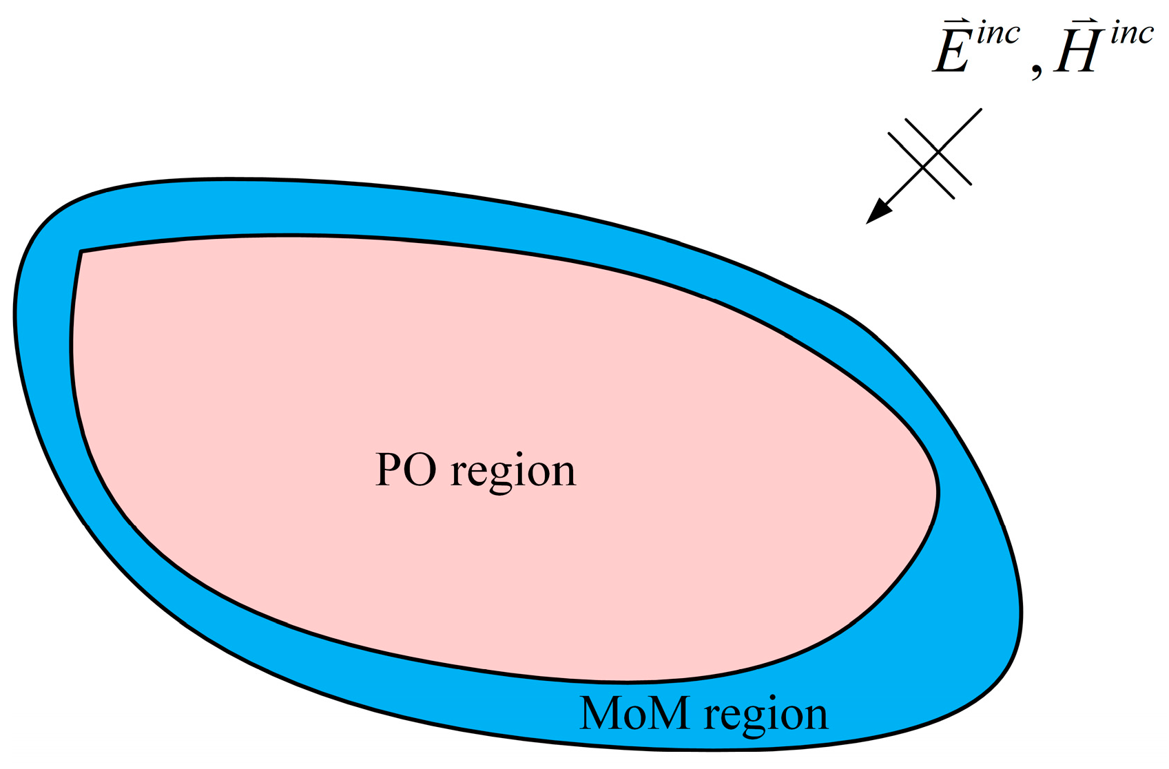
When utilizing the MoM and PO hybrid approach to solve complex EM models, it is necessary to segment the entire model into regions [34,35,36], as illustrated in Figure 1. The fundamental principle of segmentation is to achieve an accurate simulation of induced EM currents on the target surface. MoM is widely recognized for its ability to precisely compute the distribution of EM currents. Therefore, during segmentation, areas with discontinuities such as edges and corners, where the EM current changes rapidly, are assigned to the MoM region. Smooth and continuous regions are allocated to the PO region. For targets with minimal curvature changes, a small number of regions with significant scattering contributions can be designated to the MoM region, effectively enhancing the precision of this hybrid algorithm.

Figure 1.
Schematic of target impedance surface.
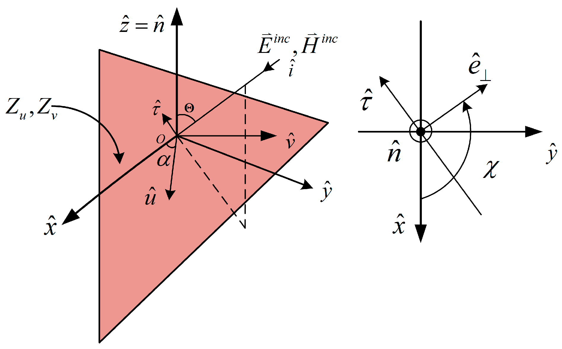
In order to describe the anisotropic characteristics of the target surface, a local reference coordinate system is established on the discretized triangular surface elements [37,38,39]. Here, and represent two-unit tangent vectors on the surface element, and is the outward normal vector. The directional vectors of the optical axis for anisotropic materials are denoted as and , as depicted in Figure 2. Specifically, the angle between and is the optical axis tilt angle, denoted by α. Additionally, χ represents the angle between the incident wave’s vertical electric field and the x-axis direction, while signifies the projection vector of the incident wave on the surface element.
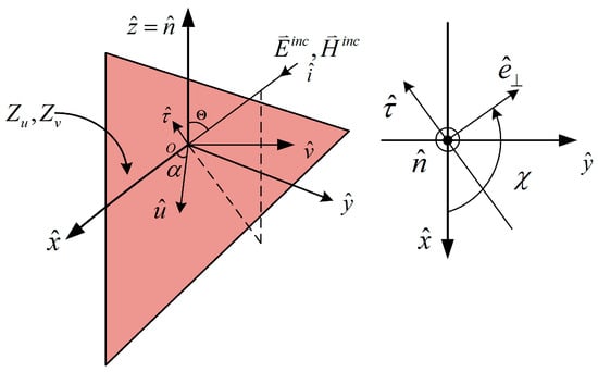
Figure 2.
Schematic of local coordinate system and anisotropic optical axis.
For a 3-D arbitrary impedance surface, the impedance dyadic within the local reference frame (xoy) can be expressed as with the free-space wave impedance Z0, where , , and [33].
The Impedance Boundary Condition (IBC) represents a relationship that the electric and/or magnetic fields satisfy on the surface of an impedance target. This condition was originally proposed by Leontovich in 1948 while investigating the propagation of radio waves around the Earth, hence also referred to as the Leontovich Impedance Boundary Condition [40]. Its mathematical expression is as follows:
and denote the electric and magnetic fields on the target surface, respectively, assumed to be harmonic and given by . represents the outward normal direction of this surface, as illustrated in Figure 2.
In conjunction with the equivalence principle [41], the EM scattering of a thin-layer medium-coated conductive target can be equivalently represented as a radiation problem of equivalent EM current sources on the impedance surface. The relationship satisfied by the equivalent EM current on the target surface can be expressed as
The preprocessing procedure of the MoM-PO method is analogous to the MoM. Initially, the region under investigation is partitioned, followed by the expansion of all unknown currents using basis functions. During this research, scattering body surface currents are uniformly expanded using vector triangular basis functions defined on planar triangular patches. These basis functions were initially introduced and applied to the EM scattering computations of three-dimensional targets by S.M. Rao, D.R. Wilton, and A.W. Glisson, hence commonly referred to as the RWG basis functions [42,43]. Mathematically, they can be represented as
Here, represents the RWG basis function, and NMM and KPO correspond to the number of basis functions in the MoM and PO regions, respectively. , , , and denote the unknown current coefficients and unknown magnetic flow coefficients in the MoM and PO regions, respectively.
The current in the PO region can be expressed as
In Equation (6), represents the direction vector of the incident wave, is the direction vector of the excitation source in the MoM region, is the scattering direction vector, and Z0 is the impedance of free space. denotes the magnetic field generated by sources in the MoM region, represents the electric field generated by sources in the MoM region, and and respectively represent the illumination factors of the nth surface current basis at the observation point and the incident field. Figure 3 illustrates the process of MoM-PO matching.
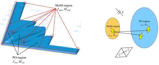
Figure 3.
The process of MoM-PO matching.
Define and as unit vectors perpendicular to the common edge at the midpoint of the k-th common edge in the PO region. At each midpoint of the common edge in the PO region, taking the dot product of with both sides of Equation (6) yields
Here, k = 1, 2, …, KPO. This provides the relationship between the current coefficients in the PO region and the incident field and the current coefficients in the MoM region. Equation (7) can be expressed in matrix form:
In which,
The matrix establishes the connection between the current in the PO region and the current in the MoM region, reflecting the excitation effect of the MoM region current on the PO region.
In the MoM region, Equation (3) can be expressed as
Utilizing the Galerkin matching technique with the trial function identical in form to the basis function [44], we obtain
where denotes the integral of the inner product between two vector functions. By combining Equations (4), (5), (8), and (11), we derive the following matrix equation:
Here, is the self-impedance matrix of the MoM region surface current basis, is the mutual impedance matrix between the MoM region surface current basis and the PO region surface current basis, and is the voltage matrix of the MoM region surface current basis, taking into account the coupling effects from the PO region.
Substituting Equation (8) into Equation (12), we obtain
Equation (11) represents the matrix equation derived from the MoM-PO hybrid method. reflects the excitation effect of the MoM region current on the PO region and can be referred to as the excitation matrix.
Solving the matrix equation iteratively using Equation (13) gives the current coefficients for the MoM region. Then, using Equation (8), one can determine the current coefficients for the PO region. As a result, the magnetic current coefficients for both the MoM and PO regions can be obtained, leading to the EM scattering characteristics of the given impedance target. When the surface impedance parameters are equal to , the algorithm simplifies to the isotropic case. If , the algorithm becomes the Perfect Electric Conductor (PEC) scenario.
3. Graphics Hardware Acceleration Technology
In the MoM-PO hybrid method, the determination of illuminated regions in the PO region involves two scenarios. One is the assessment of illuminated regions under plane wave incidence when calculating the scattering field in the PO region excited by the incident wave. The second scenario involves evaluating illuminated regions under point source incidence when computing the coupling effects between the MoM and PO regions. In previously published works, particularly focusing on simple structures such as plates and spheres, the determination of illuminated regions was accomplished solely based on the vector relationship between the outward normal of the surface element and the direction of the incident wave. However, for complex targets, where mutual occlusion between different structures may occur, relying solely on the vector relationship between the outward normal of the surface element and the direction of the incident wave might not be sufficient to fully determine the illumination status of discrete surface elements.
This study employs real-time occlusion results obtained through graphics hardware acceleration. Leveraging the rendering capabilities of GPUs and utilizing the depth buffer, the graphics rendering technique is employed to accelerate the determination of illuminated regions in the PO region.
The specific occlusion process in this paper is as follows:
- Background Elimination
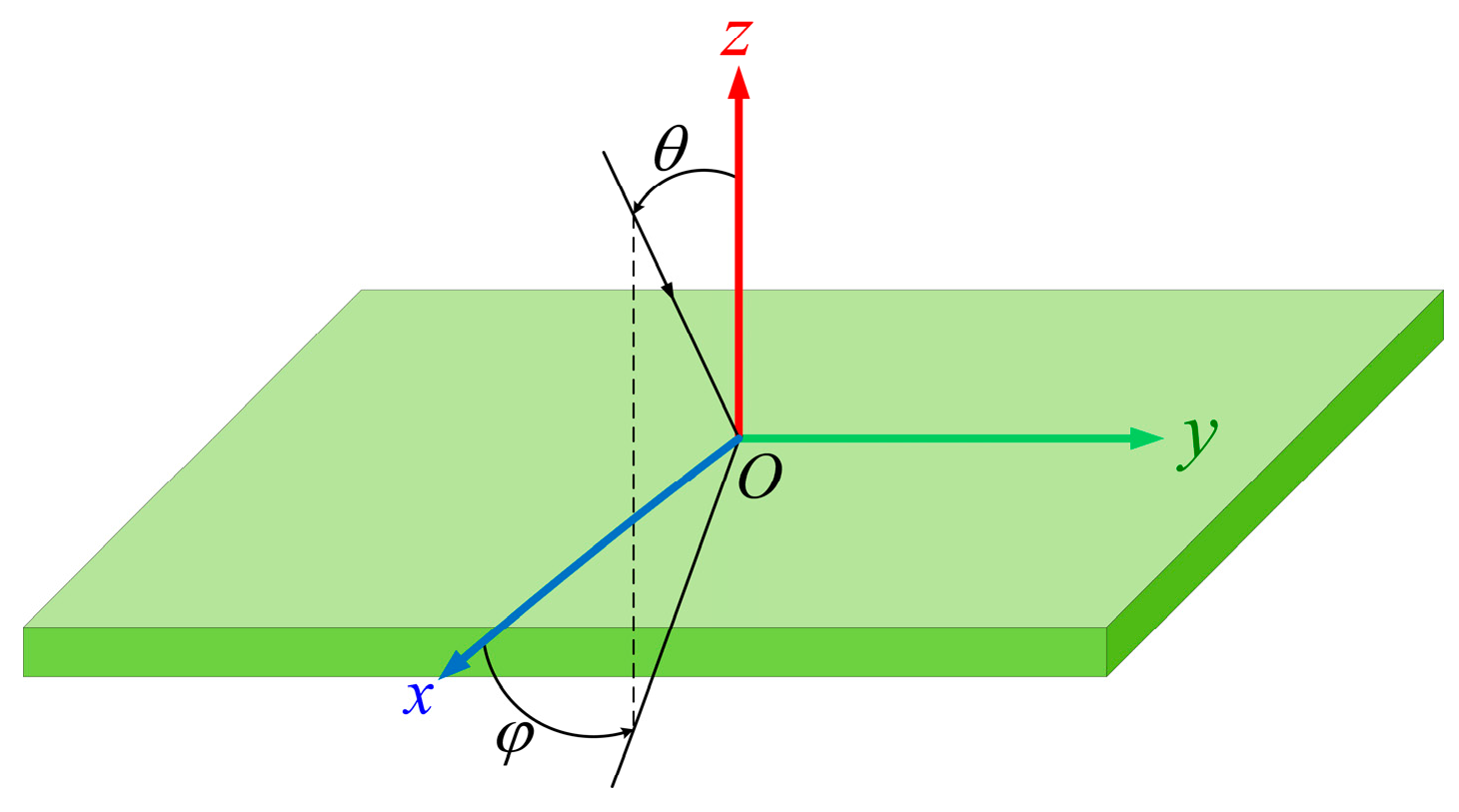
First, eliminate the backward invisible surface elements based on the angle between the outward normal of the target surface element and the direction of the incident wave. As shown in Figure 4, the angle (θ) between the incident wave direction () and the outward normal vector () of the surface element is related as follows:
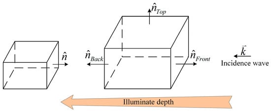
Figure 4.
Determination of visible regions on the target.
Based on the sign of this result, determine the range of θ. If the dot product is greater than 0, then θ < 90°, indicating the surface is visible, and if θ > 90°, it indicates the surface is invisible. For a single convex polyhedron, background elimination can completely eliminate invisible faces. However, for a complex structure composed of multiple objects, background elimination alone is insufficient, and further depth occlusion testing is required.
- 2.
- Projection Matrix
In the process of depth occlusion, the model space coordinate system is generally defined with the computer screen center as the origin. The viewer is facing the screen, with the right direction as the positive x-axis, upward as the positive y-axis, and the direction pointing outward from the screen as the positive z-axis. In the model space, three-dimensional objects can undergo a series of translations, rotations, and scaling using the computer’s built-in model functions to determine their size, position, and shape. The final positioning of the three-dimensional object can be achieved by multiplying the basic physical model with the model transformation matrix.
Before completing perspective projection, parameters such as the viewpoint, near plane, and far plane need to be defined. With these parameters, the projection matrix can be constructed to achieve perspective projection imaging. For convenience of explanation, let the viewpoint be at the origin of the coordinate system. Define the coordinates of the bottom-left and top-right corners of the near plane as (xl, yb) and (xr, yt), respectively. Define the near and far planes as Zn and Zf. The expression for the perspective projection matrix (P) is as follows:
The geometric interpretation of the projection matrix (P) is to map the viewing frustum onto a cube.
- 3.
- Depth Buffer
The basic concept of the depth buffer is to test a series of planes for each pixel on the display screen, recording the depth of the plane closest to the observer along the projection line for that pixel. In addition to depth, it is also necessary to record the brightness value used to display the object. The depth buffer algorithm uses two arrays: one records the depth value for each pixel, and the other records the brightness value for the corresponding object of this pixel. The process is as follows:
- (1)
- For each pixel on the screen, set the depth buffer Depth[x][y] to a large value and set the brightness buffer to the background value;
- (2)
- For each triangle face in the scene, identify all pixels within its boundary when projected onto the screen. For these pixels, calculate the depth z of this face at (x, y). If z < Depth[x][y], this face is closer to the observer at (x, y) compared to other polygons, so set Depth[x][y] = z and set the brightness array to the brightness value of this face. If z > Depth[x][y], it indicates that this polygon is obscured by other polygons at this pixel, so no action is taken.
After scanning all pixels, the depth buffer and brightness buffer contain the depth values and visible brightness values, respectively, for all visible points. Since calculations are performed using screen coordinates, the depth value at each pixel point (x, y) can be directly calculated using the following equation.
In this equation, a, b, c, and d are undetermined coefficients for the pixel point, which can be determined using the target’s geometric three-dimensional data and observation angles. In this case, when the scan line increases by one unit along the x-axis, the depth value at pixel point (x + 1, y) is
Similarly, when y = y − 1, the depth value at pixel point (x, y − 1) is
In three-dimensional rendering, the aforementioned perspective projection matrix is employed to establish the projection relationship, enabling the projection of objects from three-dimensional space onto a two-dimensional computer screen. Additionally, leveraging hardware depth testing mechanisms, precise determination of pixel visibility is achieved through the implementation of depth buffer testing in graphics hardware, facilitating an efficient occlusion process.
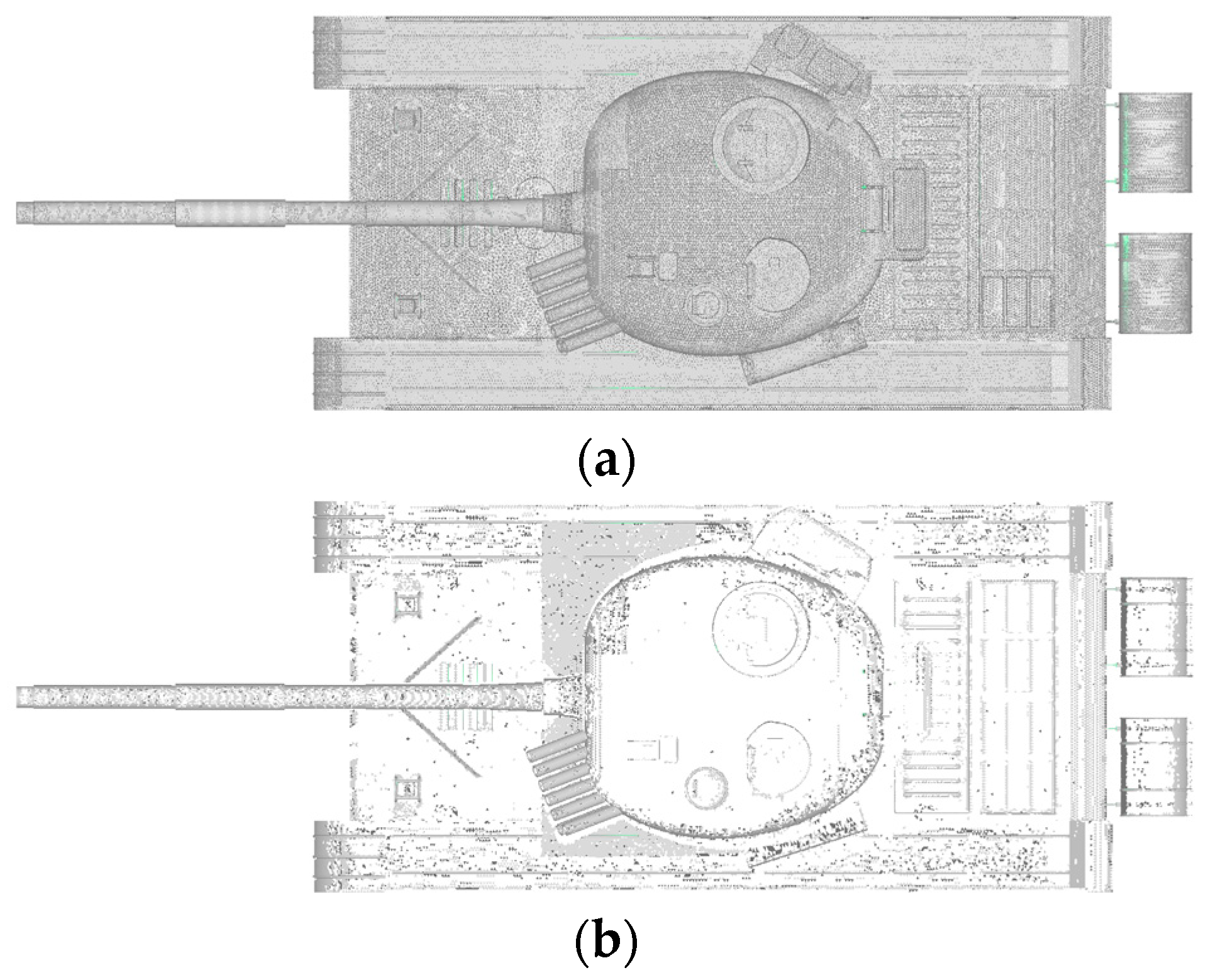
Figure 5a shows the wireframe model of a tank model before occlusion processing, while Figure 5b displays the wireframe model after occlusion. At this moment, the zenith angle (θ) of the incident radar wave is 0°, and the azimuth angle (φ) is 90°. It is evident from the figures that the occlusion process effectively removes the obscured portions of the model, resulting in a well-defined occlusion effect.
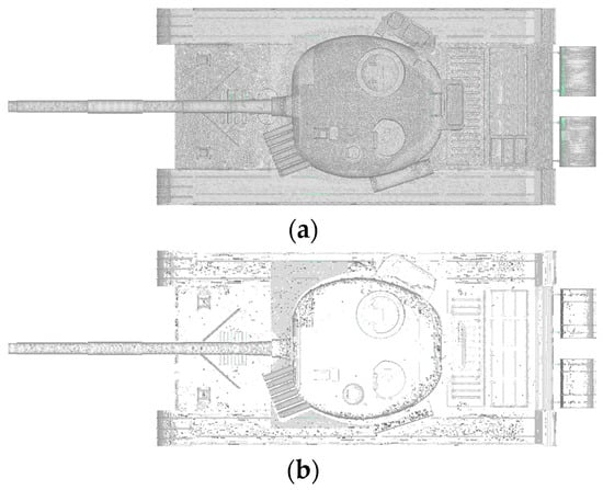
Figure 5.
Comparison of tank model for a complex aircraft target before and after occlusion. (a) Before and (b) after.
4. Numerical Results and Discussion
The analysis of the scattering characteristics of medium-coated conducting targets is closely tied to the boundary conditions on the coated surface. IBC is commonly employed to solve boundary problems at the interface between conductive materials and coating materials. When the thickness of the coated medium layer is very thin, IBC can be used to simplify the calculations. The expression for the surface impedance () of the external electric and magnetic fields of the thin-coated medium layer is given by
In which, Z0 denotes the wave impedance in free space, k0 is the propagation constant in free space, d signifies the thickness of the coated medium, and εr and μr represent the relative permittivity and relative magnetic permeability of the medium layer, respectively.
To validate the performance of the proposed hybrid method, the study selected the Method of Moments–Finite Element Method (MoM-FEM) hybrid full-wave numerical approach as a reference. The Root Mean Square Error (RMSE) is employed as the evaluation criterion to quantify the discrepancies between the research method and the reference data. The definition of RMSE is as follows:
In the equation, θ represents the scattering angle, and denote the calculated results for the proposed method and the full-wave numerical solution, respectively.
The chip set used for the computational platform is an Intel Core i7—12,700 with a clock speed of 2.10 GHz, and the total memory is 64 GB.
4.1. Square Plate
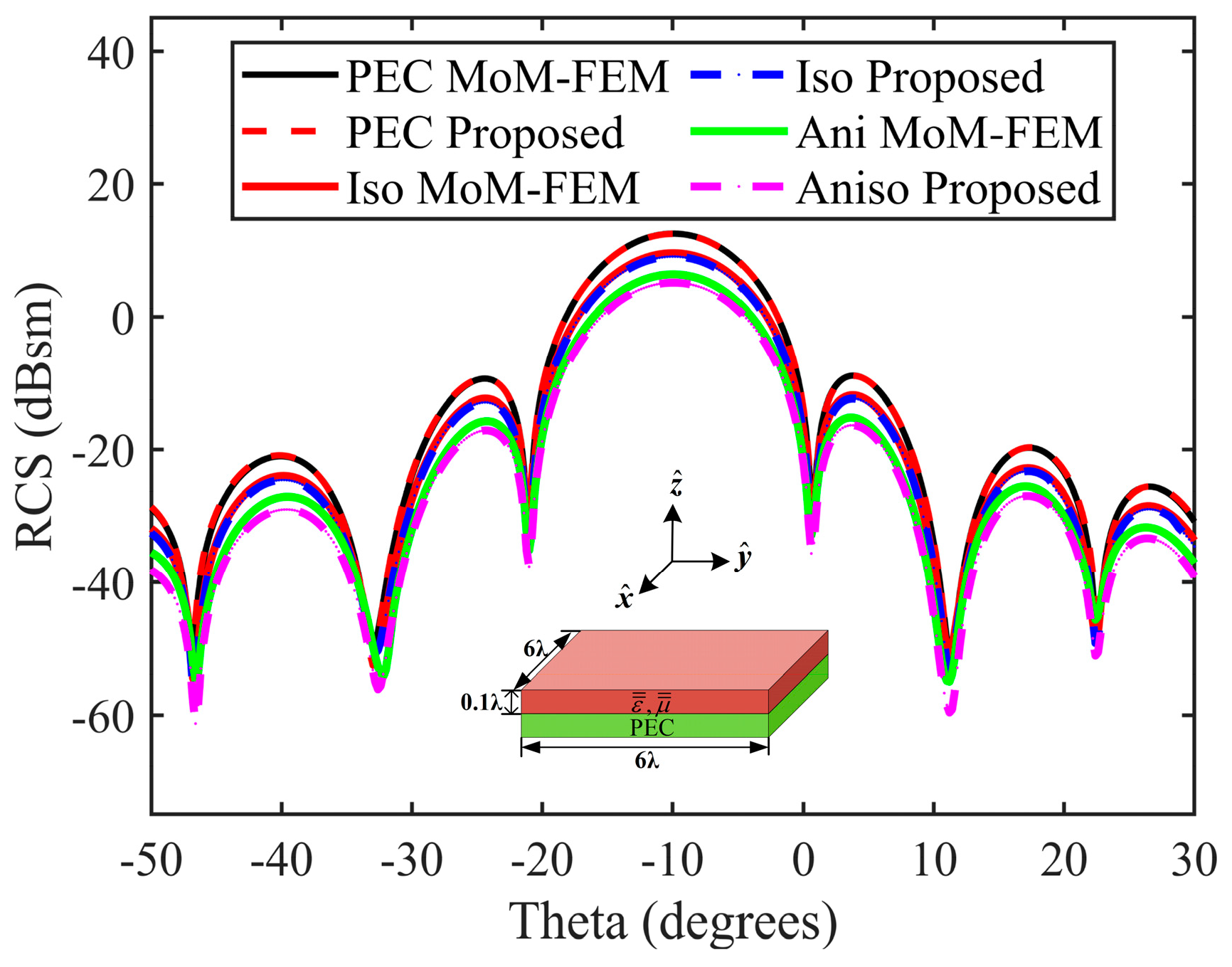
The schematic of the square plate model is shown in Figure 6. Figure 7 (VV polarization) and Figure 8 (HH polarization) respectively present the simulation results of the bistatic RCS and their comparison with the full-wave numerical solution. In this simulation, the relative permittivity for the isotropic coating is set as εr = 12–12j, while for the anisotropic coating, the relative permittivity values are εu = 5–7j and εv = 3–9j. The thickness for both coatings is d = 0.1 λ. The corresponding isotropic impedance parameters are Zu = Zv = 0.24 + j 0.03, α = 0°; and the anisotropic impedance parameters are Zu = 0.45 + j 0.20, Zv = 0.32 + j 0.23, α = 0°. For the incident conditions, the incident angle is set to θi = 10° and φi = 27°, with the scattering angle ranging from θs = –50° to 30° and φs = 27°. Furthermore, the frequency of the incident wave is 9 GHz. In the figures, “Iso” represents the scenario with isotropic medium coating, while “Aniso” denotes the scenario with anisotropic medium coating.
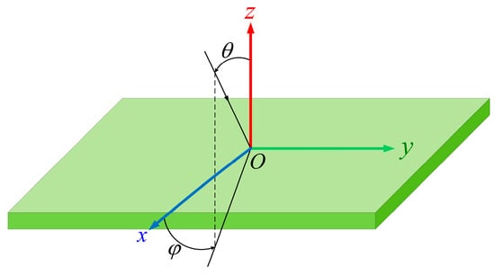
Figure 6.
Schematic of the square plate.
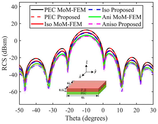
Figure 7.
Bistatic RCSs of the square plate. The RMSE for the scenarios of PEC, isotropic medium coating, and anisotropic medium coating are 0.51 dB, 0.63 dB, and 1.96 dB, respectively, for VV polarization.
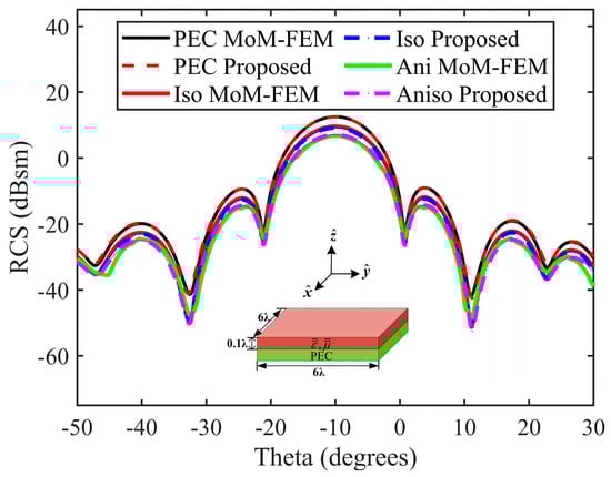
Figure 8.
Bistatic RCSs of the square plate. The RMSE for the scenarios of PEC, isotropic medium coating, and anisotropic medium coating are 0.46 dB, 0.57 dB, and 1.57 dB, respectively, for HH polarization.
The experimental results reveal that the coating medium significantly affects the RCS of the target, with the attenuation effect being particularly pronounced for the anisotropic medium. Importantly, the hybrid algorithm proposed in this research is consistent with the full-wave numerical solution in terms of the computational results. The RSME data of RCS in Table 1 indicate that the maximum error is only 2 dB, demonstrating that the precision meets the requirements for practical engineering applications and further confirming the reliability of the proposed methodology. Additionally, Figure 9, Figure 10 and Figure 11 provide a more detailed depiction of the surface current distribution of the square plate under various coating conditions, contrasted with the full-wave numerical solution. The comparative results indicate that the relative error between the two remains within 10−5, further underscoring the applicability of the approach in handling open structures such as flat plates.

Table 1.
RMSE calculation results for bistatic RCS of the square plate.
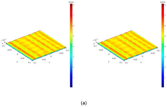
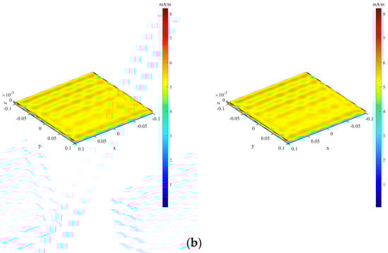
Figure 9.
Current distribution of the square plate, PEC. (Left, full wave numerical method; right, the proposed algorithm). (a) VV polarization, (b) HH polarization.
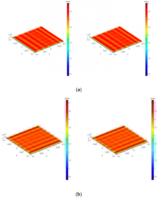
Figure 10.
Current distribution of the square plate, coated with a single-layer isotropic medium on the outer surface. (Left, full wave numerical method; right, the proposed algorithm). (a) VV polarization, (b) HH polarization.
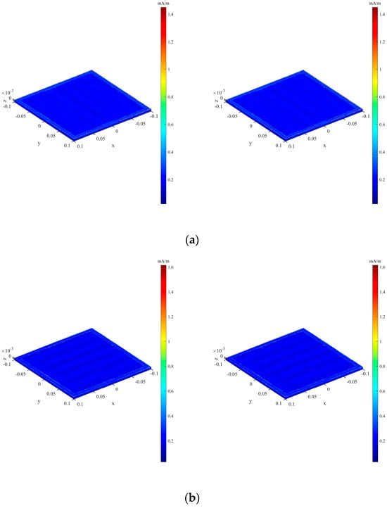
Figure 11.
Current distribution of the square plate, coated with a single-layer anisotropic medium on the outer surface. (Left, full wave numerical method; right, the proposed algorithm). (a) VV polarization, (b) HH polarization.
4.2. Aircraft Target
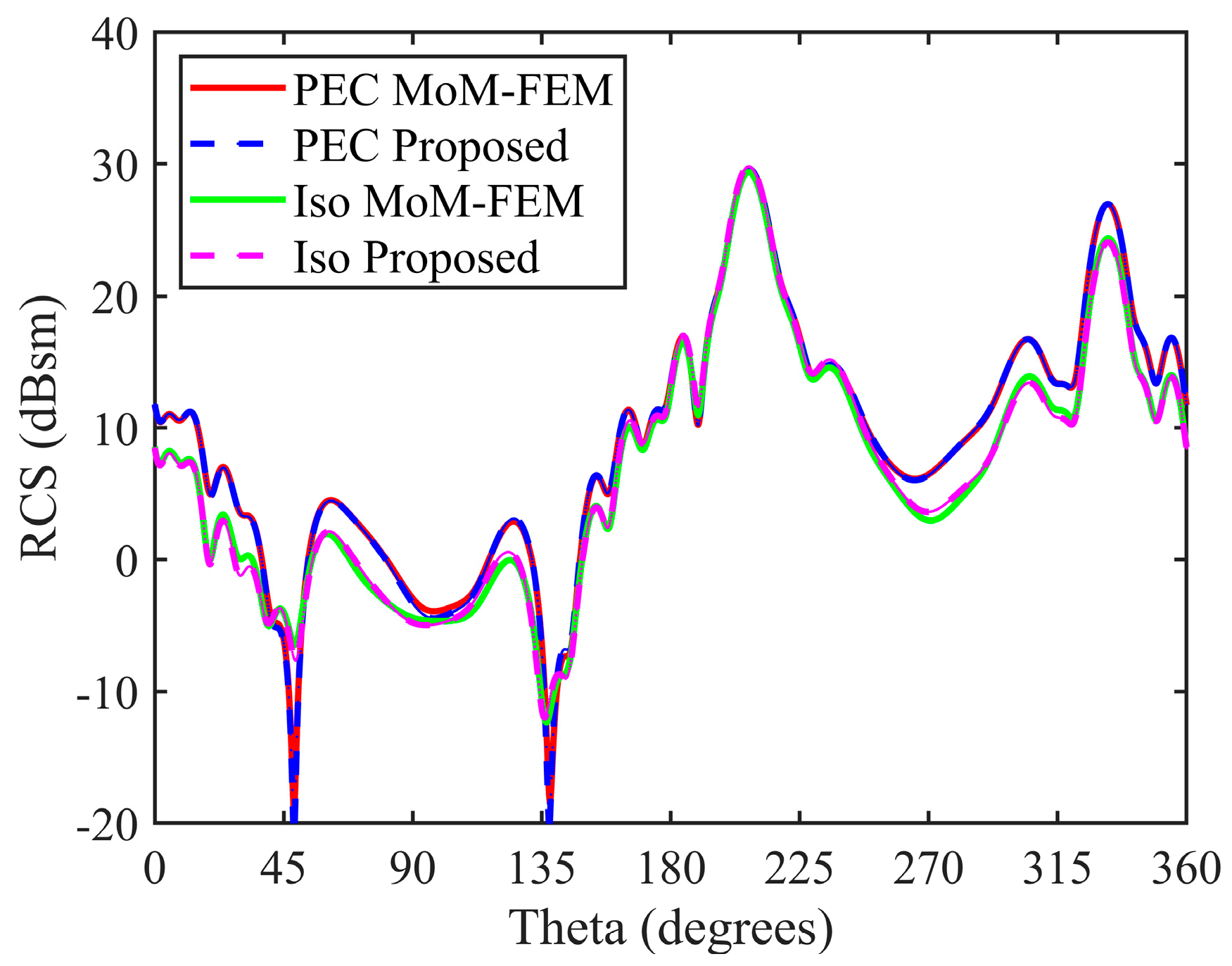
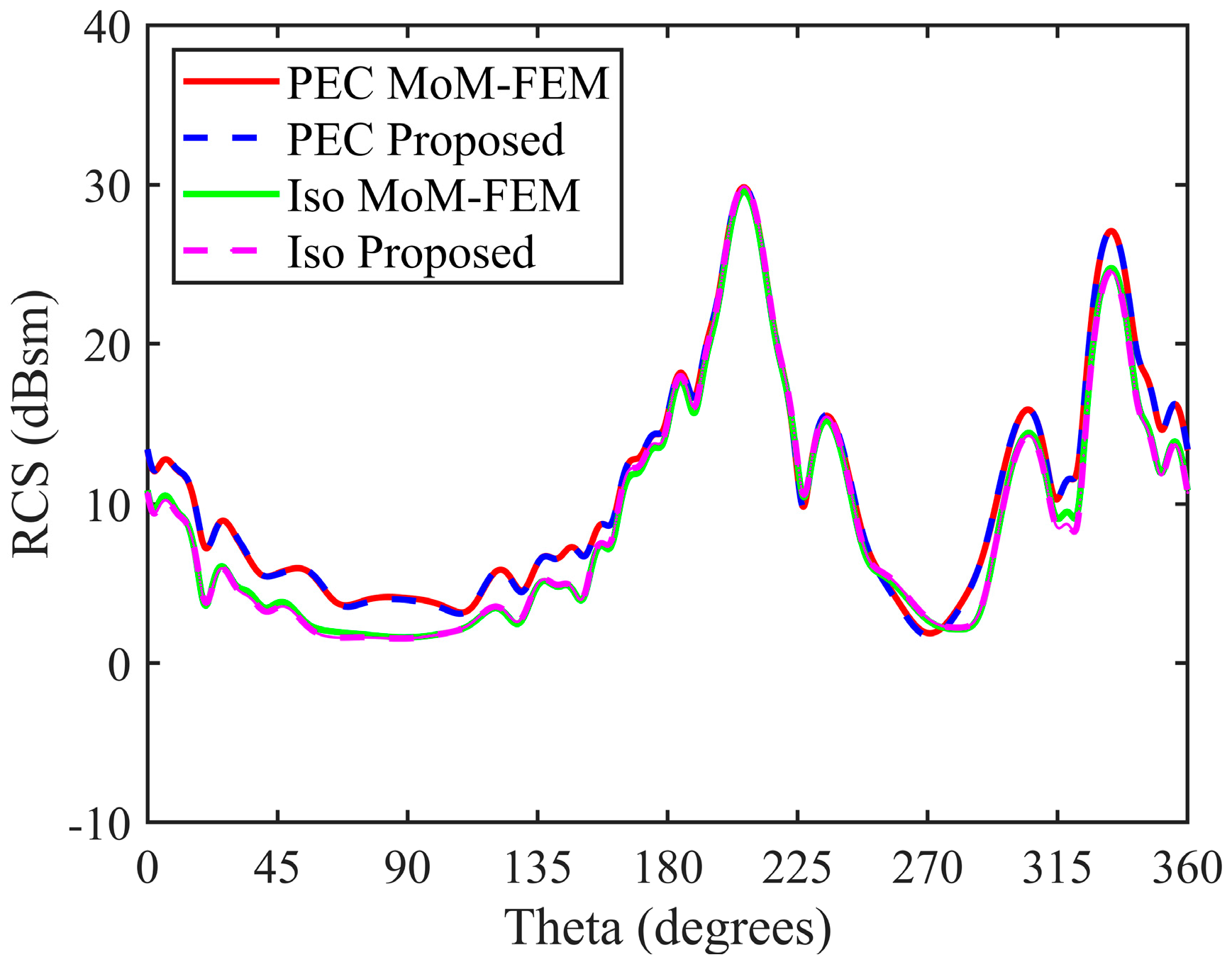
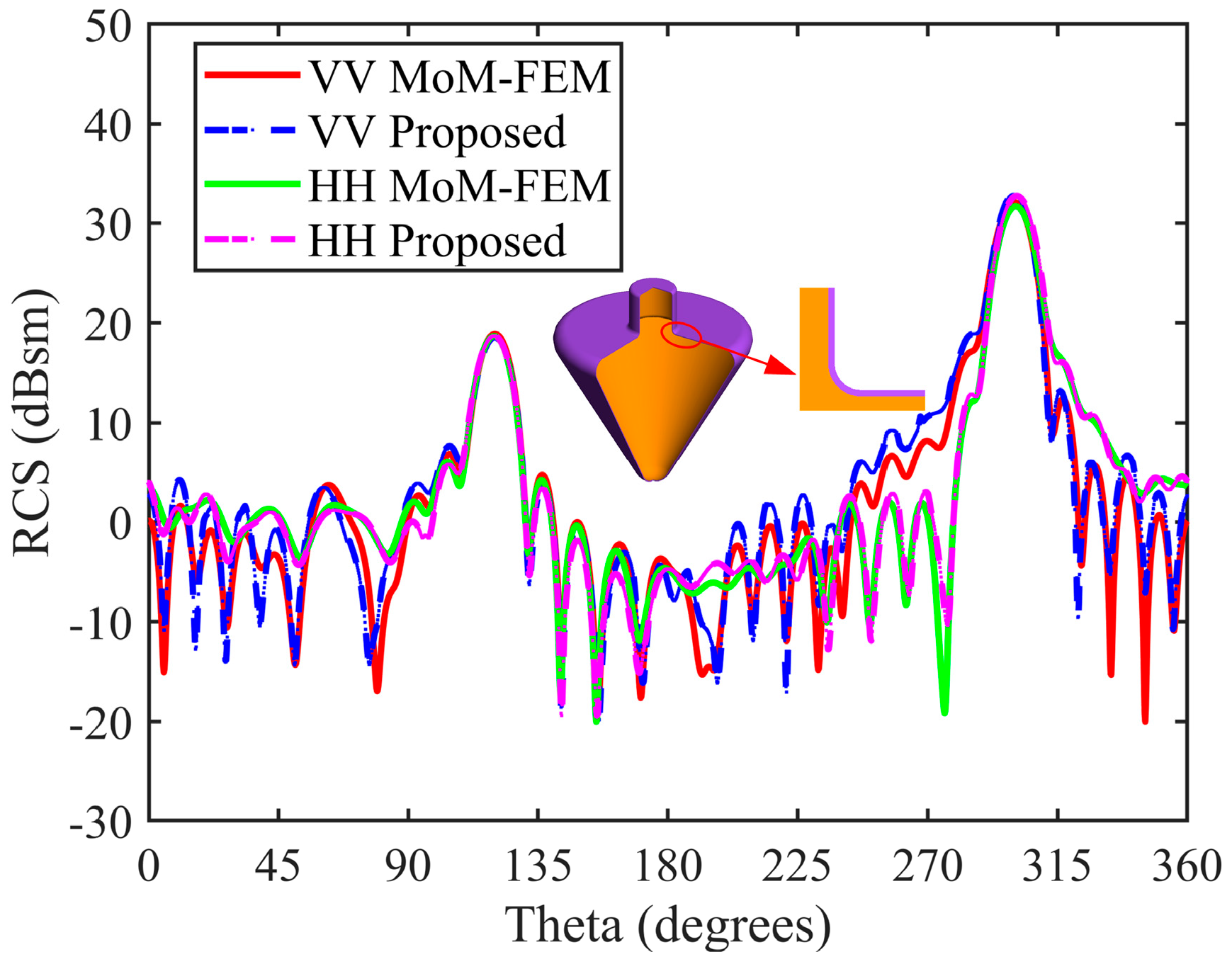
The three-dimensional model of a specific aircraft is illustrated in Figure 12, with an electrical dimension of 10.47λ. Figure 13 and Figure 14 display the bistatic RCS simulation results of the target under two conditions: ideal conductivity and isotropic medium coating, as well as for two polarizations. Table 2 provides a detailed listing of the RMSE calculations for the RCS. Surface current distributions corresponding to these simulations are depicted in Figure 15 and Figure 16. For this simulation, the incident angles are set as θi = 27° and φi = 35°, with a scattering angle range of θs = 0°–360° and φs = 35°. The frequency of the incident wave is set at 600 MHz. The relative permittivity for the isotropic medium coating is εr = 20.7–20.7j, with a coating thickness of d = 0.1λ. The corresponding isotropic impedance parameters are Zu = Zv = 0.15 + j 0.06, α = 0°.
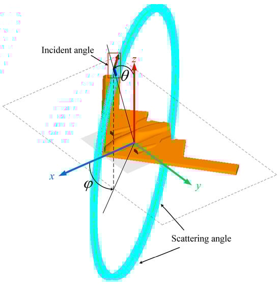
Figure 12.
Schematic of the aircraft model.
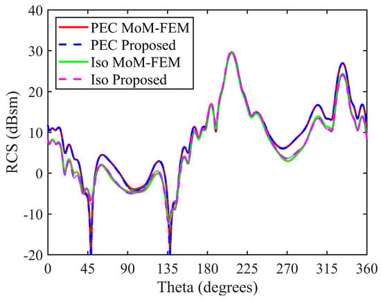
Figure 13.
Bistatic RCSs of the aircraft. The RMSEs for the cases with PEC and surface coated with isotropic medium are 0.25 dB and 0.46 dB, respectively, under VV polarization.
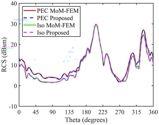
Figure 14.
Bistatic RCSs of the aircraft. The RMSEs for the cases with PEC and surface coated with isotropic medium are 0.08 dB and 0.24 dB, respectively, under HH polarization.
Table 2.
RMSE calculation results for bistatic RCS of the aircraft.
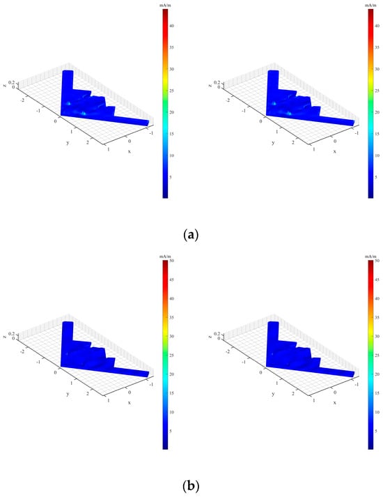
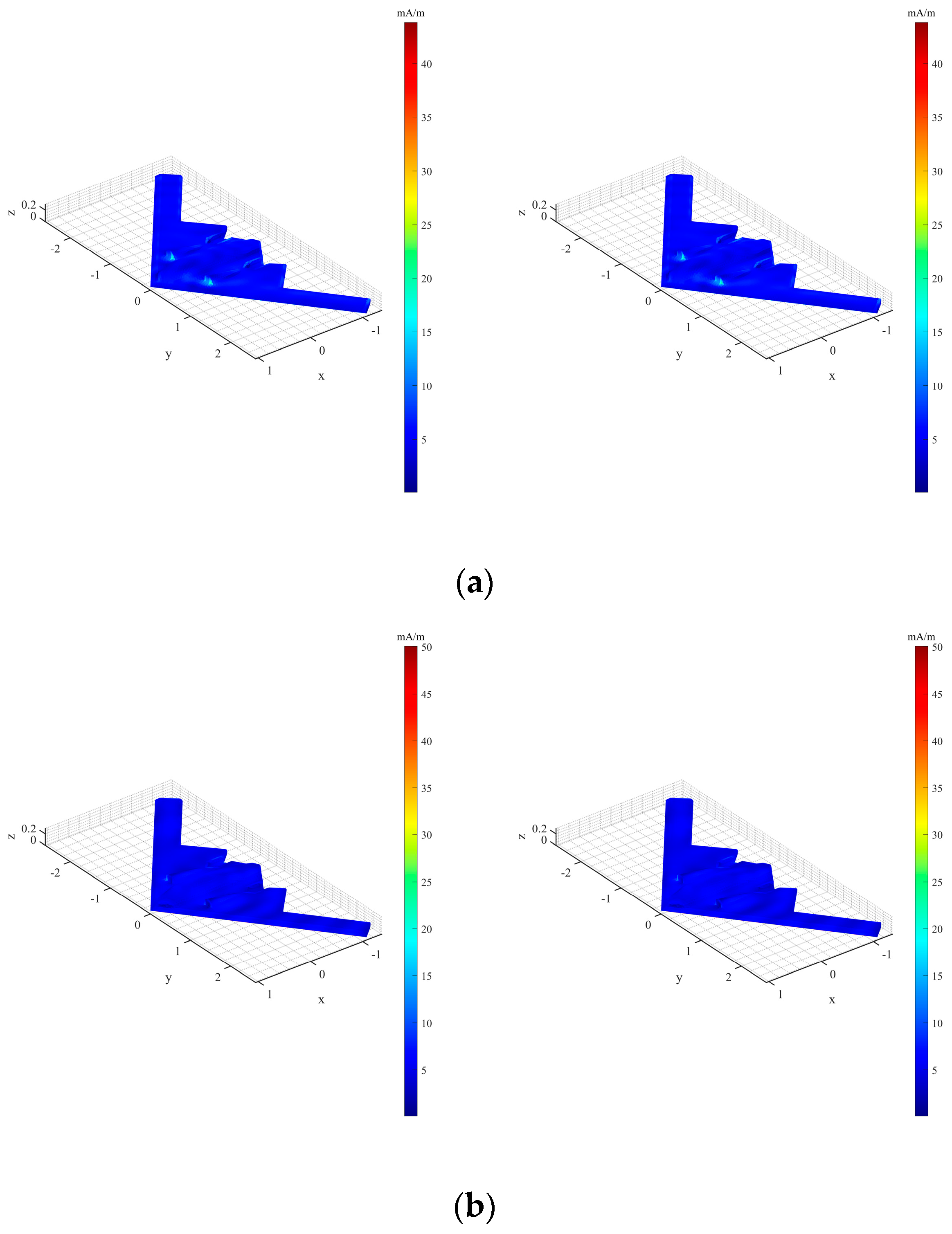
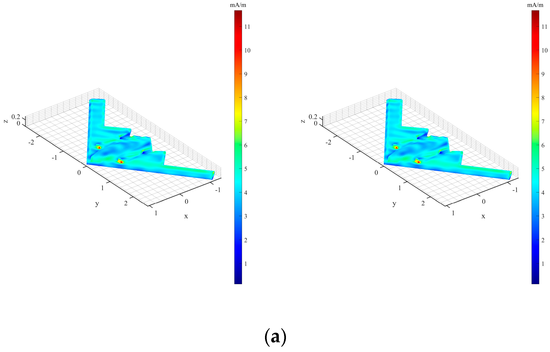
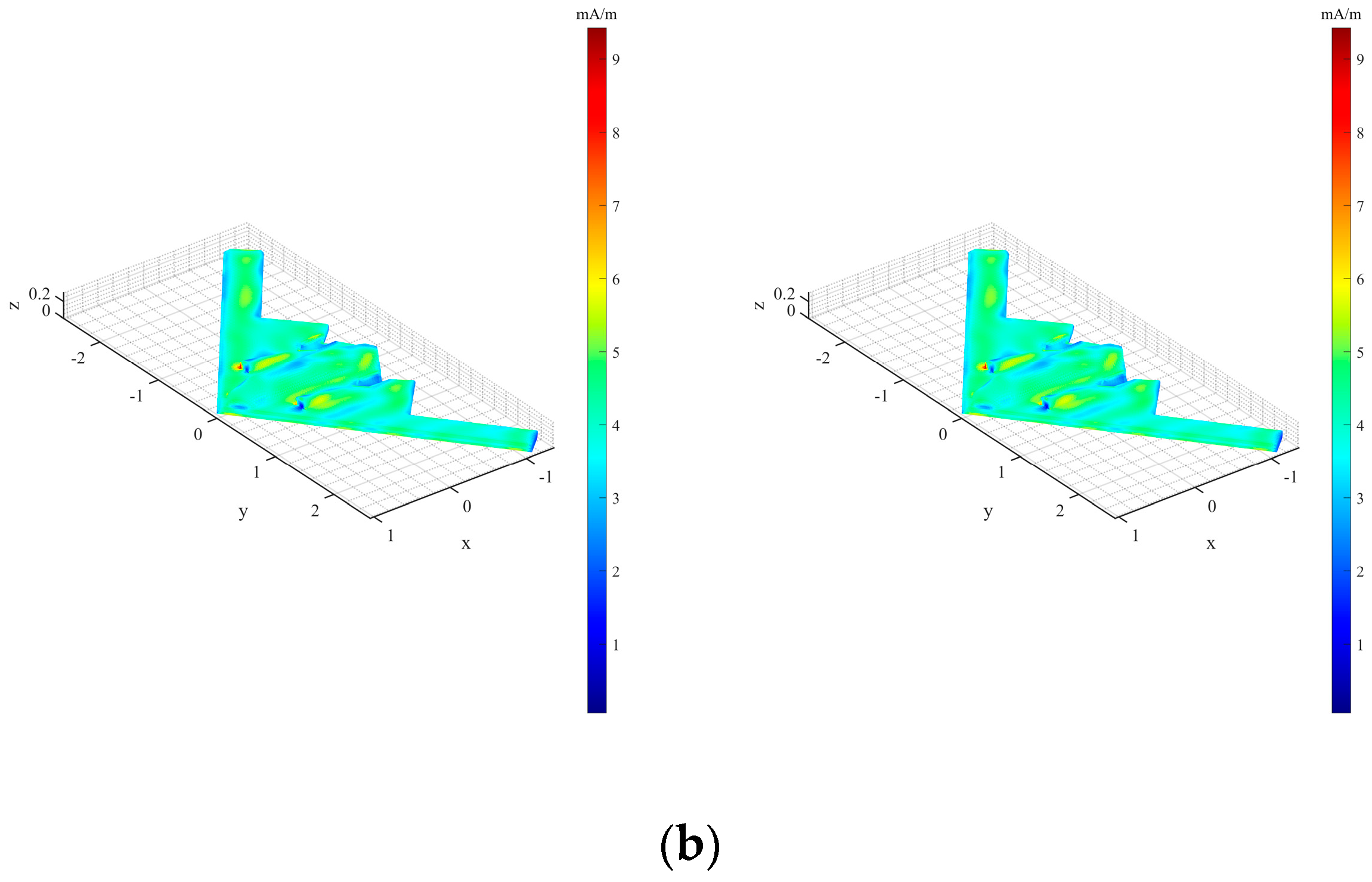
Figure 15.
Current distribution of the aircraft, PEC. (Left, full wave numerical method; right, the proposed algorithm). (a) VV polarization, (b) HH polarization.

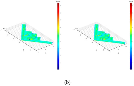
Figure 16.
Current distribution of the aircraft, coated with a single-layer isotropic medium on the outer surface. (Left, full wave numerical method; right, the proposed algorithm). (a) VV polarization, (b) HH polarization.
The simulation results reveal that within the observation angle range of 0–180° and 275–360°, the medium layer on the metal target surface significantly attenuates the incident EM waves. Furthermore, the scattering characteristics of the target vary under different polarization conditions, a feature widely exploited in radar systems for detection and identification purposes. Comparative analysis demonstrates that the algorithm proposed in this research exhibits excellent consistency with the full-wave numerical solutions over a broad angular range, with an RMSE not exceeding 0.5 dB. The surface current distribution agrees with the numerical computations, underscoring the efficacy and accuracy of the method presented in this paper for EM scattering simulations of complex structures such as aircraft.
4.3. Complex Satellite Target
The three-dimensional schematic of the Misty stealth satellite is illustrated in Figure 17. The simulated bistatic RCS outcomes are presented in Figure 18 and Figure 19. The incident angles are defined as θi = 120° and φi = 30°, with a scattering angle range of θs = 0°–360° and φs = 30°. The frequency of the incident wave is set at 800 MHz, and the target’s electrical dimension stands at 10λ. The relative permittivity values for the anisotropic medium layer are εu = 2–5j and εv = 3–7j, with a coating thickness denoted as d = 0.04λ. The corresponding anisotropic impedance parameters are Zu = 0.03 + j 0.26, Zv = 0.04 + j 0.26, α = 0°. In this study, we juxtapose our approach with the full-wave numerical method, and the RMSEs for RCS are tabulated in Table 3. The distributions of surface currents on the target are depicted in Figure 20 and Figure 21. Additionally, Table 4 furnishes data on the memory footprint and CPU computation durations for both our devised method and the full-wave numerical technique.
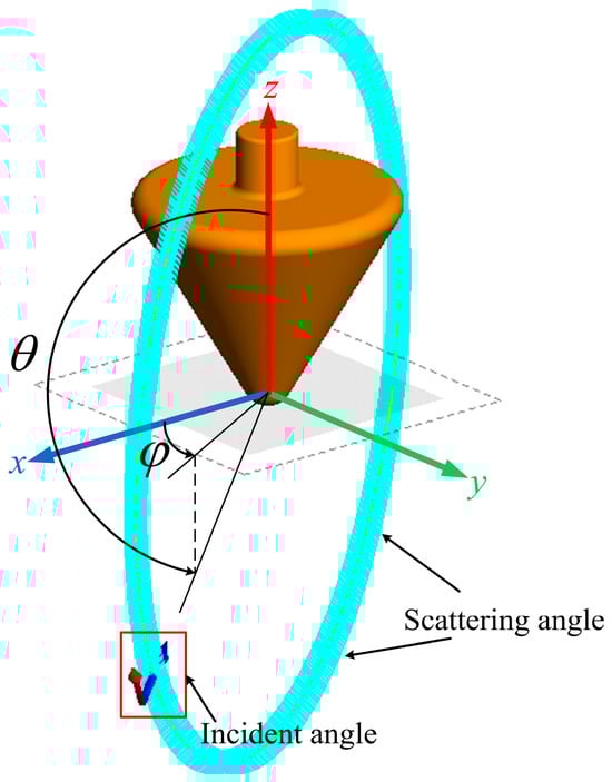
Figure 17.
Schematic of the Misty satellite model.
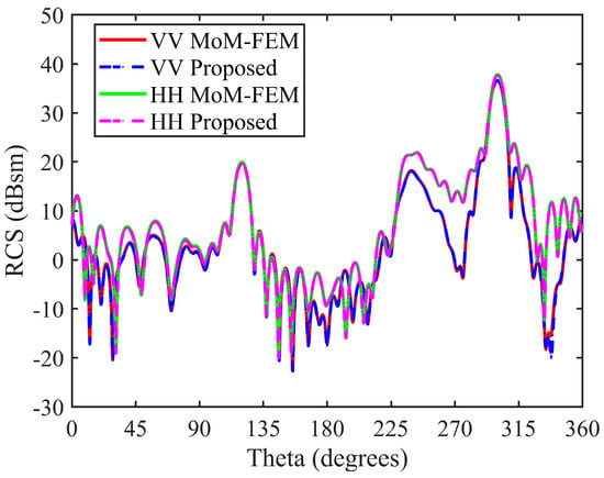
Figure 18.
Bistatic RCSs of Misty, PEC. The RMSEs are 0.41 dB (VV polarization) and 0.22 dB (HH polarization).

Figure 19.
Bistatic RCSs of Misty, coated with a single-layer anisotropic medium on the outer surface. The RMSEs are 2.64 dB (VV polarization) and 2.52 dB (HH polarization).
Table 3.
RMSE calculation results for bistatic RCS of the Misty.
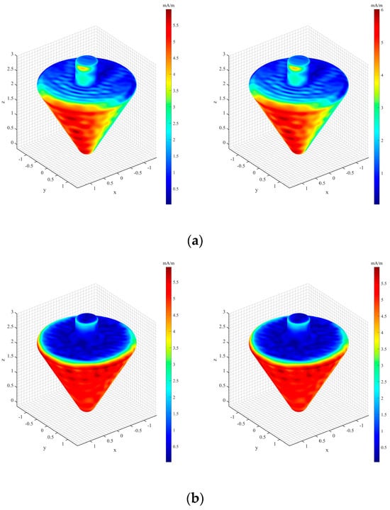
Figure 20.
Current distribution of the Misty, PEC. (Left, full wave numerical method; right, the proposed algorithm). (a) VV polarization, (b) HH polarization.
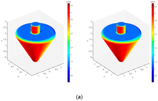
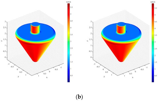
Figure 21.
Current distribution of the Misty, coated with a single-layer anisotropic medium on the outer surface. (Left, full wave numerical method; right, the proposed algorithm). (a) VV polarization, (b) HH polarization.
Table 4.
Comparison of computation time and memory requirements for the Misty satellite.
Misty’s geometric structure exhibits significant complexity, necessitating effective occlusion and determination of the PO region illumination within the observation angle. The research reveals that the adopted anisotropic medium layer in this study contributes to a pronounced attenuation in the target’s EM scattering, particularly within the observation angle range of 225–300°. Under varying polarization conditions, the target manifests distinct EM scattering characteristics. A comparison with the full-wave numerical method confirms the high consistency of the algorithm proposed in this study. Whether in scenarios of PEC or those with anisotropic coating, the computational outcomes align closely with the numerical method, with the maximum root mean square error of RCS being only 2.64 dB. This further underscores the feasibility and accuracy of the proposed methodology for intricate targets. Notably, the computational resource comparison in Table 4 reveals that, in contrast to the conventional approach, our method efficiently reduces the number of unknowns in the MoM region matrix operation to one-tenth of the original. Concurrently, there are substantial improvements in both memory requirements and computational time, with an average enhancement exceeding 50%, highlighting the efficiency of the hybrid algorithm employed in this research. In summary, adopting the approach proposed in this paper facilitates precise and rapid estimation of the RCS for complex coated targets.
5. Conclusions
This paper proposes an IBC-MoM-PO hybrid algorithm tailored for efficiently addressing the EM scattering of complex targets with anisotropic medium coatings. Initially, leveraging graphical hardware acceleration expedites the determination process of the PO illumination region. Subsequently, by integrating IBC and the principle of equivalence, the EM scattering problem of a medium-coated conductive target is transformed into an equivalent EM current radiation issue on the impedance surface. This ensures a high-precision and rapid estimation of the EM scattering characteristics of coated targets. The validation examples in this study encompass square plates, a specific model of aircraft, and the Misty satellite. Using bistatic RCS and surface current distribution as evaluation criteria, the proposed algorithm consistently demonstrates superior performance and effectiveness.
Future research endeavors will focus on augmenting the feasible electrical dimensions of targets, optimizing computational speed, and enhancing the memory utilization efficiency of the algorithm. Concurrently, there are plans to integrate the approach presented in this paper with existing rapid multipole algorithms or other efficient techniques such as multilayer UV methods, aiming for broader applications in practical engineering challenges.
Author Contributions
Methodology, S.H.; Validation, M.H.; Formal analysis, M.H.; Investigation, M.H. All authors have read and agreed to the published version of the manuscript.
Funding
This research received no external funding.
Data Availability Statement
The data presented in this study are available on request from the corresponding author.
Conflicts of Interest
The authors declare no conflict of interest.
References
- Richardson, D. Stealth Warplanes: Deception. Evasion and Concealment in the Air (London, 1989); Orion Books: London, UK, 2001. [Google Scholar]
- Lynch, D. Introduction to Stealth Systems; IET Digital Library: London, UK, 2004. [Google Scholar]
- Guo, S.J.; Wu, Y.M.; Wang, C.M.; Jin, Y.Q. Analysis of the Electrically Large Target in Isotropic Medium by the Physical Optics Method with Adaptive Mesh Technique. IEEE Trans. Antennas Propag. 2023, 71, 6027–6036. [Google Scholar] [CrossRef]
- Yang, Z.; Yuan, X.-W.; Huang, X.-W.; Yang, M.-L.; Sheng, X.-Q. Resistive Sheet Boundary Condition-Based Nonconformal Domain Decomposition FE-BI-MLFMA for Electromagnetic Scattering from Inhomogeneous Objects with Honeycomb Structures. IEEE Trans. Antennas Propag. 2022, 70, 9483–9496. [Google Scholar] [CrossRef]
- Mao, Y.; Zhan, Q.; Wang, D.; Zhang, R.; Liu, Q.H. Modeling Thin 3-D Material Surfaces Using a Spectral-Element Spectral- Integral Method with the Surface Current Boundary Condition. IEEE Trans. Antennas Propag. 2021, 70, 2375–2380. [Google Scholar] [CrossRef]
- Rao, Z.; Zhu, G.; He, S.; Li, C.; Yang, Z.; Liu, J. Simulation and Analysis of Electromagnetic Scattering from Anisotropic Plasma-Coated Electrically Large and Complex Targets. Remote. Sens. 2022, 14, 764. [Google Scholar] [CrossRef]
- Coşğun, S.; Bilgin, E.; Çayören, M. Quasi-Newton-Based Inversion Method for Determining Complex Dielectric Permittivity of 3-D Inhomogeneous Objects. IEEE Trans. Antennas Propag. 2022, 70, 4810–4817. [Google Scholar] [CrossRef]
- Guan, Z.; Liu, J.; Zhuang, M.; Liu, Q.H. A Hybrid SESI Method for Electromagnetic Scattering by Objects in Multiregion Cylindrically Layered Media. IEEE Trans. Microw. Theory Technol. 2021, 69, 3967–3975. [Google Scholar] [CrossRef]
- Chakarothai, J.; Watanabe, S.; Wake, K. Numerical Dosimetry of Electromagnetic Pulse Exposures Using FDTD Method. IEEE Trans. Antennas Propag. 2018, 66, 5397–5408. [Google Scholar] [CrossRef]
- Huang, X.W.; Yang, M.L.; Sheng, X.Q. A simplified discontinuous Galerkin self-dual integral equation formulation for electro-magnetic scattering from extremely large IBC objects. IEEE Trans. Antennas Propag. 2021, 70, 3575–3586. [Google Scholar] [CrossRef]
- Davoudabadifarahani, H.; Ghalamkari, B. Rigorous EM Scattering Solution from a Slit in an IBC Plate with Different Surface Impedances Placed Between Two Different Chiral Media. IEEE Trans. Antennas Propag. 2022, 70, 10843–10850. [Google Scholar] [CrossRef]
- Huang, X.-W.; Sheng, X.-Q. A Discontinuous Galerkin Self-Dual Integral Equation Method for Scattering from IBC Objects. IEEE Trans. Antennas Propag. 2019, 67, 4708–4717. [Google Scholar] [CrossRef]
- Chen, C.; Yang, F.; Hu, C.; Zhou, J. An Improved RCS Calculation Method for Power Lines Combining Characteristic Mode with SMWA. Electronics 2022, 11, 2051. [Google Scholar] [CrossRef]
- Zhao, Z.H.; Wu, B.Y.; Li, Z.L.; Yang, M.L.; Sheng, X.Q. An adaptive rational fitting technique of Sommerfeld integrals for the efficient MoM analysis of planar structures. Electronics 2022, 11, 3940. [Google Scholar] [CrossRef]
- Delgado, C.; García, E.; Cátedra, F. Fast Hybrid Computational Technique for the Analysis of Radome Structures Using Dual Domain Decomposition. Electronics 2021, 10, 2196. [Google Scholar] [CrossRef]
- Pons, A.; Somolinos, A.; González, I.; Cátedra, F. Fast Computation by MLFMM-FFT with NURBS in Large Volumetric Dielectric Structures. Electronics 2021, 10, 1560. [Google Scholar] [CrossRef]
- Paez-Rueda, C.I.; Fajardo, A.; Pérez, M.; Perilla, G. Closed-Form Expressions for Numerical Evaluation of Self-Impedance Terms In-volved on Wire Antenna Analysis by the Method of Moments. Electronics 2021, 10, 1316. [Google Scholar] [CrossRef]
- Florencio, R.; Somolinos, A.; González, I.; Cátedra, F. Method of Moments Based on Equivalent Periodic Problem and FFT with NURBS Surfaces for Analysis of Multilayer Periodic Structures. Electronics 2020, 9, 234. [Google Scholar] [CrossRef]
- Sanchez-Olivares, P.; Lozano, L.; Somolinos, A.; Cátedra, F. EM Modelling of Monostatic RCS for Different Complex Targets in the Near-Field Range: Experimental Evaluation for Traffic Applications. Electronics 2020, 9, 1890. [Google Scholar] [CrossRef]
- Hailu, D.M.; Ehtezazi, I.A.; Neshat, M.; Shaker, G.S.A.; Safavi-Naeini, S. Hybrid Spectral-Domain Ray Tracing Method for Fast Analysis of Millimeter-Wave and Terahertz-Integrated Antennas. IEEE Trans. Terahertz Sci. Technol. 2011, 1, 425–434. [Google Scholar] [CrossRef]
- Jakobus, U.; Landstorfer, F. Improved PO-MM hybrid formulation for scattering from three-dimensional perfectly conducting bodies of arbitrary shape. IEEE Trans. Antennas Propag. 1995, 43, 162–169. [Google Scholar] [CrossRef]
- Jakobus, U.; Landstorfer, F.M. Improvement of the PO-MoM hybrid method by accounting for effects of perfectly conducting wedges. IEEE Trans. Antennas Propag. 1995, 43, 1123–1129. [Google Scholar] [CrossRef]
- Theron, I.; Davidson, D.; Jakobus, U. Extensions to the hybrid method of moments/uniform GTD formulation for sources located close to a smooth convex surface. IEEE Trans. Antennas Propag. 2000, 48, 940–945. [Google Scholar] [CrossRef]
- Mendil, S.; Aguili, T. Analysis of Electromagnetic Scattering in Waveguides by Hybrid MOM-PO-GTD Method. In Proceedings of the 2019 IEEE 19th Mediterranean Microwave Symposium (MMS), Hammamet, Tunisia, 31 October–2 November 2019; pp. 1–5. [Google Scholar]
- Ozzaim, C.; Umakoglu, I. A MoM-PO Hybrid Solution for TM Plane Wave Scattering by a Buried Conducting Cylinder. In Proceedings of the 2017 International Applied Computational Electromagnetics Society Symposium-Italy (ACES), Firenze, Italy, 26–30 March 2017; pp. 1–2. [Google Scholar]
- Guo, L.; Li, M.; Xu, S.; Yang, F.; Li, J. Modeling of Multiscale Wave Interactions Based on an Iterative Scheme of MoM-PO-EPA Algorithm. Electronics 2022, 11, 990. [Google Scholar] [CrossRef]
- Zhou, H.; Wang, X.-H.; Xiao, L.; Wang, B.-Z. Efficient EDM-PO Method for the Scattering from Electrically Large Objects with the High-Order Impedance Boundary Condition. IEEE Trans. Antennas Propag. 2022, 70, 8242–8249. [Google Scholar] [CrossRef]
- Xue, Z.Y.; Wu, Y.M.; Jin, Y.Q. An Efficient iterative MoM-PO Hybrid Method for Calculating Scattered Fields of the Multiscale and Multiphysics Scatterers. In Proceedings of the 2020 IEEE MTT-S International Conference on Numerical Electromagnetic and Multiphysics Modeling and Optimization (NEMO), Hangzhou, China, 7–9 December 2020; pp. 1–3. [Google Scholar]
- Xiao, L.; Wang, X.H.; Wang, B.Z.; Zheng, G.; Chen, P. An efficient hybrid method of iterative MoM-PO and equivalent dipole-moment for scattering from electrically large objects. IEEE Antennas Wirel. Propag. Lett. 2017, 16, 1723–1726. [Google Scholar] [CrossRef]
- Akbaş, M.; Alatan, L.; Ergül, Ö. Accuracy and efficiency improvements in iterative hybridization of the method of moments (MoM) and physical optics (PO). In Proceedings of the 2016 10th European Conference on Antennas and Propagation (EuCAP), Davos, Switzerland, 10–15 April 2016; pp. 1–5. [Google Scholar]
- Andrés-García, B.; González-Ovejero, D.; Craeye, C.; García-Muñoz, L.E.; Segovia-Vargas, D. An iterative MoM-PO method based on a MBF/Krylov approach. In Proceedings of the Fourth European Conference on Antennas and Propagation, Barcelona, Spain, 12–16 April 2010; pp. 1–4. [Google Scholar]
- Yla-Oijala, P.; Koivumaki, P.; Jarvenpaa, S. Hybrid Multilevel Fast Multipole Algorithm—Physical Optics for Impedance Surfaces. IEEE Trans. Antennas Propag. 2016, 64, 5475–5478. [Google Scholar] [CrossRef]
- Yu, D.F.; He, S.Y.; Chen, X.; Zhu, G.Q.; Yin, H.C. Simulation of electromagnetic scattering for 3-D impedance surface using MoM-PO method. IEEE Trans. Antennas Propag. 2012, 60, 3988–3991. [Google Scholar] [CrossRef]
- Djordjevic, M.; Notaros, B. Higher order hybrid method of moments-physical optics modeling technique for radiation and scattering from large perfectly conducting surfaces. IEEE Trans. Antennas Propag. 2005, 53, 800–813. [Google Scholar] [CrossRef]
- Gong, Z.; Xiao, B.; Zhu, G.; Ke, H. Improvements to the hybrid MoM-PO technique for scattering of plane wave by an infinite wedge. IEEE Trans. Antennas Propag. 2006, 54, 251–255. [Google Scholar] [CrossRef]
- Chen, H.T.; Zhu, G.Q.; Luo, J.X.; Yuan, F. A modified MoM-PO method for analyzing wire antennas near to coated PEC plates. IEEE Trans. Antennas Propag. 2008, 56, 1818–1822. [Google Scholar] [CrossRef]
- Lin, M.C. Applied Computational Geometry. Towards Geometric Engineering: FCRC’96 Workshop, WACG’96; Selected Papers; Springer Science & Business Media: Philadelphia, PA, USA, 1996. [Google Scholar]
- Letniowski, F.W. Three-Dimensional Delaunay Triangulations for Finite Element Approximations to a Second-Order Diffusion Operator. SIAM J. Sci. Stat. Comput. 1992, 13, 765–770. [Google Scholar] [CrossRef]
- Lo, S.H. A new mesh generation scheme for arbitrary planar domains. Int. J. Numer. Methods Eng. 1985, 21, 1403–1426. [Google Scholar] [CrossRef]
- Leontovich, M.A. Investigations on Radiowave Propagation, Part II; Printing House of the Academy of Sciences: Moscow, Russia, 1948; pp. 5–12. [Google Scholar]
- Umashankar, K.; Taflove, A.; Rao, S. Electromagnetic scattering by arbitrary shaped three-dimensional homogeneous lossy die-lectric objects. IEEE Trans. Antennas Propag. 1986, 34, 758–766. [Google Scholar] [CrossRef]
- Glisson, A.; Wilton, D. Simple and efficient numerical methods for problems of electromagnetic radiation and scattering from surfaces. IEEE Trans. Antennas Propag. 1980, 28, 593–603. [Google Scholar] [CrossRef]
- Rao, S.; Wilton, D.; Glisson, A. Electromagnetic scattering by surfaces of arbitrary shape. IEEE Trans. Antennas Propag. 1982, 30, 409–418. [Google Scholar] [CrossRef]
- Harrington, R.F.; Harrington, J.L. Field Computation by Moment Methods; Oxford University Press, Inc.: Oxford, UK, 1996. [Google Scholar]


Disclaimer/Publisher’s Note: The statements, opinions and data contained in all publications are solely those of the individual author(s) and contributor(s) and not of MDPI and/or the editor(s). MDPI and/or the editor(s) disclaim responsibility for any injury to people or property resulting from any ideas, methods, instructions or products referred to in the content. |
© 2024 by the authors. Licensee MDPI, Basel, Switzerland. This article is an open access article distributed under the terms and conditions of the Creative Commons Attribution (CC BY) license (https://creativecommons.org/licenses/by/4.0/).