Article

Transient Stability Analysis for Grid-Connected Renewable Power Generation Systems Based on LMI Optimization Modelling

1
State Grid Chongqing Economic Research Institute, Chongqing 401120, China
2
School of Electrical Engineering, Chongqing University of Science and Technology, Chongqing 401331, China
*
Author to whom correspondence should be addressed.
Electronics 2024, 13(24), 5052; https://doi.org/10.3390/electronics13245052
Submission received: 3 November 2024 / Revised: 12 December 2024 / Accepted: 14 December 2024 / Published: 23 December 2024

Abstract

:
Grid-connected renewable power generation systems (RPGSs) may be disconnected from the grid under a transient process, which may possibly induce large-scale power outage accidents. Optimization of parameters based on transient stability analysis of RPGSs would be a feasible solution to such a problem. However, the accurate stability boundary of a grid-connected RPGS are hard to obtain, as the commonly used transient stability analysis methods have the problems of large computation burden with no quantitative solution (numerical method), low analysis accuracy (equal area method), and complexity or impossibility in implementation (Lyapunov function-based methods). In this paper, a modified transient stability analysis method is proposed. By calculating the largest area of the domain of attraction (LEDA) based on the linear matrix inequality (LMI) method and optimization modelling, and then applying parameter sensitivity analysis to the LEDA, the dominant parameters that have high impacts on the LEDA are revealed. A parameter optimization design method that can improve the system’s transient stability is eventually obtained. A hardware-in-the-loop (HIL) simulation system of a 2 MW grid-connected RPGS is established based on the Typhoon HIL 602 device. The theoretical results are verified by using HIL simulation results.

1. Introduction

Countries all over the world are vigorously developing renewable energy, as it is one of the main ways to achieve the goals of carbon peak and carbon neutrality [1,2,3]. Typically, renewable power generation systems (RPGSs) are connected to the utility power grid through grid-connected inverters. At present, most of these inverters are grid-following inverters, whose performance highly depends on the stability of grid voltage [4,5]. When the voltage at the grid connection point fluctuates, especially when voltage sag appears, it is introduced into the system control through a phase-locked loop (PLL and current loop, etc.), which greatly impacts the stability of grid-connected operation [6]. As RPGSs are prone to transient instability, they are more likely to be disconnected from the grid. Such an event may trigger large-scale power outage accidents if many renewable power generation sources or farms are disconnected at the same time due to transient instability [7,8].
The integration of RPGSs such as photovoltaic and wind power into the grid varies in system scale. Some systems have large and complex structures [9], while others may include only a single power generation unit [10]. The differing structures and scales of these systems also affect the determination of system stability. This paper focuses on analyzing an RPGS with a single unit, while larger and more complex systems can be converted to the type of system studied here using equivalent methods [11], thus allowing for stability assessment using the proposed method. Furthermore, as grid-connected inverter technology continues to develop, emerging technologies such as utility-interactive multilevel inverters have enhanced the power quality of grid integration [12]. However, the application of these emerging technologies is still not widespread. Therefore, this study primarily focuses on traditional RPGSs.
The modeling of an RPGS is the foundation and prerequisite for analyzing the system’s stability. Stability issues of RPGSs are generally categorized into two types: small-signal stability and large-signal stability (i.e., transient stability). Among these, small-signal stability is primarily analyzed using impedance-based methods (including the Thevenin model [13] and the Norton model [14]) and eigenvalue-based methods [15], which have been extensively studied [16]. However, such linear systems are not suitable for transient stability analysis, which involves high-order nonlinear and strongly coupled dynamics. Transient stability analysis typically employs models of RPGSs such as state–space models [1,3], piecewise linear models [17,18], and discrete time models [19,20]. Among these, the state–space modeling approach is recognized for its generality, scalability, and adaptability. This paper adopts and further improves the traditional state–space model for the analysis.
Furthermore, by finding the parameters that dominate the system’s transient stability and applying proper design, the transient stability would be greatly enhanced [19,21]. Currently, many transient stability analysis studies have been carried out [2,22,23,24,25,26,27,28]. Generally, these methods can be categorized into numerical methods [2,22,23], equal area methods [24], and Lyapunov function-based methods [25,26,27].
The numerical methods can mainly be divided into the time domain simulation method and the asymptotic expansion method. As the former method has high reliability, it is often used as the standard for testing other transient stability analysis methods. In [22], the influence of different penetration rates of renewable energy on the transient stability of distributed generation systems is explored, which provides certain guidance for the stability design of grid-connected RPGSs. However, the time domain simulation method needs to establish an accurate model of the system and solve high-order nonlinear differential equations, which requires a large amount of computing resources, making it hard to implement. In addition, this method cannot provide a quantitative stability boundary of the system, which makes it impossible to explore the stability mechanism of the system. In [2,23], the principle, advantages, and disadvantages of the asymptotic expansion method are discussed in detail. It is also used to analyze the transient stability of power systems with large amounts of renewable power penetration. However, this method requires a small number of nonlinear variables in the system. When dealing with large-scale and high-dimensional complex systems, the calculation time increases significantly.
Currently, one of the most commonly used transient stability analysis methods is the equal area method since it has a clear physical meaning and a simple calculation process. This method establishes a second-order equation similar to that of a traditional synchronous machine for the grid-connected RPGS so as to analyze the transient stability of the power angle of the system. In [24], a grid-connected inverter model with a PLL is established, and a swing equation similar to that of traditional synchronous machines is obtained. The transient characteristics of the swing equation under three types of transient disturbances are analyzed by using the equal area criterion. Obviously, the transient stability analysis based on the equal area method depends on the simplified model (second order) of the RPGS, ignoring the complex dynamic connections between various states and the influence of multiple random disturbances. As a result, the analyzing accuracy can hardly be assured.
As for the Lyapunov function-based methods, they can directly judge the system stability by constructing appropriate Lyapunov functions without obtaining the solution of the system state equation. Bahram I. D. used the Lyapunov direct method to analyze the transient synchronous stability of the grid-connected RPGS and obtained the transient stability boundary of the system [25]. Goksu O. used the Lyapunov function method to analyze the global stability of an RPGS under different grid impedances [26,27]. Although Lyapunov function-based methods are universal, Lyapunov functions are difficult to obtain as the order of the system increases, making the analysis impossible to carry out. In addition, the analysis results may be conservative, making it difficult to obtain an accurate transient stability boundary. Some other Lyapunov function-based methods, like the mixed-potential theory-based method and the T-S fuzzy model-based method, can also be found in the literature [20,29,30,31,32]. Although these methods use other theories to help find the propitiate Lyapunov functions for stability analysis, which simplify the analysis, they either ignore the control dynamics or have a curse of dimensionality problem, making the application of these methods still limited.
To address the aforementioned issues, this paper proposes a modified transient stability analysis method. The main contributions of this work are as follows:
  • Calculating the largest estimated domain of attraction (LEDA) based on the linear matrix inequality (LMI) method and optimization modeling, which accurately characterizes the system’s stability boundary.
  • Applying parameter sensitivity analysis to the LEDA, thereby revealing the influence of parameter variations on system stability. Based on this, a parameter optimization design method is proposed, where the LEDA is used to determine the parameter range that ensures system stability.
The proposed method provides a more precise depiction of the stability domain, offering theoretical significance by advancing the development of stability analysis techniques. Additionally, it holds practical engineering value, as the identified influence of parameter variations on stability and the determination of feasible parameter ranges based on LEDA can guide system design in real-world applications, improving performance in practical scenarios. The remainder of this thesis is analyzed as follows: the model of the considered RPGS is established in Section 2. In Section 3, the transient stability analysis is carried out by calculating the LEDA. The dominant parameters that affect the stability boundary most are obtained by finding the relationships among LEDA and different system parameters using sensitivity analysis. In Section 4, hardware-in-the-loop simulations are performed to verify the validity of the theory. Conclusions are finally drawn in Section 5.

2. The Modeling of Grid-Connected RPGS

The RPGS usually connects to the grid through a grid-following inverter. The prevalent control strategy for this inverter under normal operation is voltage and current dual-loop control: The outer voltage loop indirectly controls the DC-side voltage by adjusting the reference signal of the inner current loop, thereby maintaining the DC voltage constant; the inner current loop ensures precise tracking of the given reference signal by rapidly adjusting the inverter’s output current. However, during overload and severe grid faults, the grid-connected inverter typically enters a current-limiting control mode, disconnecting the outer voltage loop and retaining only the inner current loop. As the system’s transient stability analysis primarily focuses on grid fault conditions, this paper’s modeling disregards the dynamics of the outer voltage loop control, concentrating solely on the dynamics of inner current loop and PLL.

2.1. System Structure and Parameters

As depicted in Figure 1, the general topology of a grid-connected RPGS is presented, where Udc represents the DC-side voltage of the inverter; E signifies the port voltage of the inverter; Uo denotes the grid connection point voltage; Ug is the grid voltage; Io is the grid current; IL refers to the inductive current; Lf and Cf are the filter inductance and capacitance of the LC filter; Rg and Lg are the equivalent resistance and inductance between the grid connection point and the grid; θPLL is the phase angle determined by the PLL; [iod, ioq] and [uod, uoq] are the dq-axis components of the output voltage and the current of the RPGS, respectively; [Iodref, Ioqref] are the dq-axis components of the current loop set values; and [ud, uq] and [ed, eq] are the dq-axis components of the current loop output before and after considering control delay.
During the transient process, the PLL significantly impacts system stability [33]. To address this, the PLL parameters are designed as follows:
From Figure 1, the transfer function of the PLL can be derived as:
G P L L ( s ) = s k p U n + k i U n s 2 + s k p U n + k i U n = s 2 s 2 + 2 ξ ω n s + ω n 2
where ξ and ωn represent the damping ratio and the undamped natural frequency, respectively, given by:
ξ = k p U n 2 ω n ω n = k i U n
To ensure optimal dynamic and steady-state performance of the PLL, the PLL bandwidth is designed as fPLL = 60 Hz, expressed as:
G P L L ( j 2 π f P L L ) = 1 2
From Equations (1) and (3), the following can be further derived:
f P L L = 1 2 π [ ω n 1 + 2 ξ 2 + 2 + 4 ξ 2 + 4 ξ 4 + ω 0 ]
To enhance the dynamic response of the PLL, the damping ratio is set to 0.707. Using Equation (4), the natural frequency is calculated as ωn = 30.61 rad/s. Based on Equation (2), the ideal PI controller parameters for the PLL are determined to be kp = 43.28 and ki = 936.82. After considering practical simulation adjustments, the final selected values are kp = 50 and ki = 900.
The primary parameters of the system are illustrated in Table 1 [33].

2.2. State–Space Modeling of the Grid-Connected RPGS

From Figure 1, the system PLL equation is obtained as:
δ ˙ = Δ ω Δ ω ˙ = k p u ˙ o q + k i u o q
The current loop equation is:
u d   = k p c   i o d r e f   i g d + k i c   i o d r e f   i g d d t ω P L L L f i g q + u o d u q   = k p c   i o q r e f   i g q + k i c i o q r e f   i g q d t + ω P L L L f i g d + u o q
where [igd, igq] are the dq-axis components of the grid current.
The system has control delay, which can be approximated as:
G d ( s ) = e s T d 0.5 s T d + 1 0.5 s T d + 1
Combing Figure 1 and Equation (7), we have:
e ˙ d = ( 2 u d 2 e d ) / T d u ˙ d e ˙ q = ( 2 u q 2 e q ) / T d u ˙ q
From Figure 1, the system’s voltage and current equations can be obtained as:
L f i ˙ L d = e d u o d + ω P L L + δ ˙ L f i L q L f i L 1 q = e q u o q ω P L L + δ ˙ L f i L d C f u ˙ o d = i L d i g d + ω P L L + δ ˙ C f u o q + C f R d i L d i ˙ g d ω P L L + δ ˙ i L q i g q C f u ˙ o q = i L q i g q ω P L L + δ ˙ C f u o d + C f R d i L q i ˙ g q + ω P L L + δ ˙ i L d i g d L g i ˙ g d + R g i g d = u o d U g cos δ + ω P L L + δ ˙ L g i g q L g i ˙ g q + R g i g q = u o q + U g sin δ ω P L L + δ ˙ L g i g d
where [iLd, iLq] are the dq-axis components of the filter output current.
Taking the system state variables as xfull = [x1, x2, …, x12]T = [δ, Δω, ud, uq, ed, eq, iLd, iLq, uod, uoq, igd, igq]T, the system model can be organized into a standard form, resulting in a set of 12th-order nonlinear differential equations, which is also the full-order model of the grid-connected RPGS:
x ˙ 1 = x 2 x ˙ 2 = k p x ˙ 10 + k i x 10 x ˙ 3 = k p c   i ˙ o d r e f   x ˙ 11 + k i c   i o d r e f   x 11 ω P L L L f x ˙ 12 + x ˙ 9 x ˙ 4 = k p c   i ˙ o q r e f   x ˙ 12 + k i c i o q r e f   x 12 + ω P L L L f x ˙ 11 + x ˙ 10 x ˙ 5 = 2 x 3 2 x 5 / T d x ˙ 3 x ˙ 6 = 2 x 4 2 x 6 / T d x ˙ 4 x ˙ 7 = x 5 x 9 / L f + ω P L L + x 2 x 8 x ˙ 8 = x 6 x 10 / L f ω P L L + x 2 x 7 x ˙ 9 = x 7 x 11 / C f + ω P L L + x 2 x 10 + R d x 7 x ˙ 11 ω P L L + x 2 x 8 x 12 x ˙ 10 = x 8 x 12 / C f ω P L L + x 2 x 9 + R d x 8 x ˙ 12 + ω P L L + x 2 x 7 x 11 x ˙ 11 = x 9 U g cos x 1 / L g + ω P L L + x 2 x 12 R g x 11 / L g x ˙ 12 = x 10 + U g sin x 1 / L g ω P L L + x 2 x 11 R g x 12 / L g
It is evident that the full-order model of the grid-connected RPGS has a high order and contains nonlinear terms introduced by the PLL and two dq coordinate transformations. Moreover, complex coupling relationships also arise between the current loop and the PLL due to the relationships among the deviation angle δ, filter inductance Lf, and grid current IL. Consequently, the full-order model of the grid-connected RPGS exhibits characteristics of high order, nonlinearity, and strong coupling features. To facilitate the analysis, it is necessary to perform some degree of order reduction.

2.3. Model Order Reduction and Accuracy Analysis

Reduced-Order Model

As discerned from Equation (10), the current loop and the PLL in the full-order model are mutually coupled, which can easily lead to system instability due to their interaction during operation. Direct application of this model for transient stability analysis of grid-connected inverter systems poses significant challenges. Therefore, it is necessary to simplify the model. The simplification of the model in this paper is based on the following assumptions:
  • The non-critical influencing factors, such as LC filters, control delays, and feed-forward effects, are neglected.
  • The bandwidth of the PLL is much smaller than that of the current loop. Hence, it is assumed that [Iod, Ioq] approximately tracks the current loop set values [Iodref, Ioqref] in real time.
From Figure 1, Uo and Io can be expressed as:
U o = ( U o d + j U o q ) e j θ P L L I o = ( I o d + j I o q ) e j θ P L L
The grid voltage Ug can be expressed as:
U g = U g e j θ g
The equivalent line impedance Zg can be represented as:
Z g = R g + j ω P L L L g
where ωPLL is the PLL angular frequency.
From Figure 1, it is known that Uo and Ug satisfy:
U o = U g + Z g I o = U g + ( R g + j ω P L L L g ) I o
Multiplying both sides of Equation (14) by ePLL, we obtain:
U o d + j U o q = U g e j ( θ g θ P L L ) + ( R g + j ω P L L L g ) ( I o d + j I o q ) = U g cos ( θ P L L θ g ) + R g I o d ω P L L L g I o q + j U g sin ( θ P L L θ g ) + R g I o q + ω P L L L g I o d
That is:
U o d = U g cos δ + R g I o d ω P L L L g I o q U o q = U g sin δ + R g I o q + ω P L L L g I o d
Figure 2 is the structure of the PLL, where kp and ki are the proportional and integral parameters of the PI controller of the PLL, respectively, and ΔωPLL is the difference between the angular frequency of the PLL, ωPLL, and the grid angular frequency ωg, and ΔωPLL = ωPLLωg.
Combining Equation (16), the equivalent control structure can be derived as Figure 3. Taking the state variables as [x1, x2] = [δ, kiUtqdt]:
x ˙ 1 = k p U o q + x 2 x ˙ 2 = k i U o q
Substituting Equation (17) into Equation (16), it can be derived that:
x ˙ 1 = k p ( R g I o q + ω g L g I o d U g sin x 1 ) + x 2 1 k p L g I o d x ˙ 2 = k i ( R g I o q + ω g L g I o d U g sin x 1 ) + k i L g I o d x 2 1 k p L g I o d
From Equation (18), it can be seen that the system equilibrium point is:
( x 1 , e , x 2 , e ) = ( arcsin R g I o q + ω g L g I o d U g , 0 )
To ease analysis, the system is shifted to the equilibrium point, that is:
x ^ 1 = x 1 x 1 , e x ^ 2 = x 2
Thus, substituting Equation (20) into Equation (18), we obtain:
x ^ ˙ 1 = k p ( R g I o q + ω g L g I o d U g sin ( x ^ 1 + x 1 , e ) ) + x ^ 2 1 k p L g I o d x ^ ˙ 2 = k i ( R g I o q + ω g L g I o d U g sin ( x ^ 1 + x 1 , e ) ) + k i L g I o d x ^ 2 1 k p L g I o d
Let U0 = Rg + ωgLgIod, and replace [ x ^ 1 , x ^ 2 ] with [x1, x2], from which the following is derived:
x ˙ 1 = k p ( U 0 U g sin ( x 1 + x 1 , e ) ) + x 2 1 k p L g I o d x ˙ 2 = k i ( U 0 U g sin ( x 1 + x 1 , e ) ) + k i L g I o d x 2 1 k p L g I o d
To facilitate subsequent transient stability analysis, Equation (22) must be converted into a polynomial form. The sin(x1 + x1,e) in Equation (22) can be expanded using a Taylor polynomial at x1 = 0.
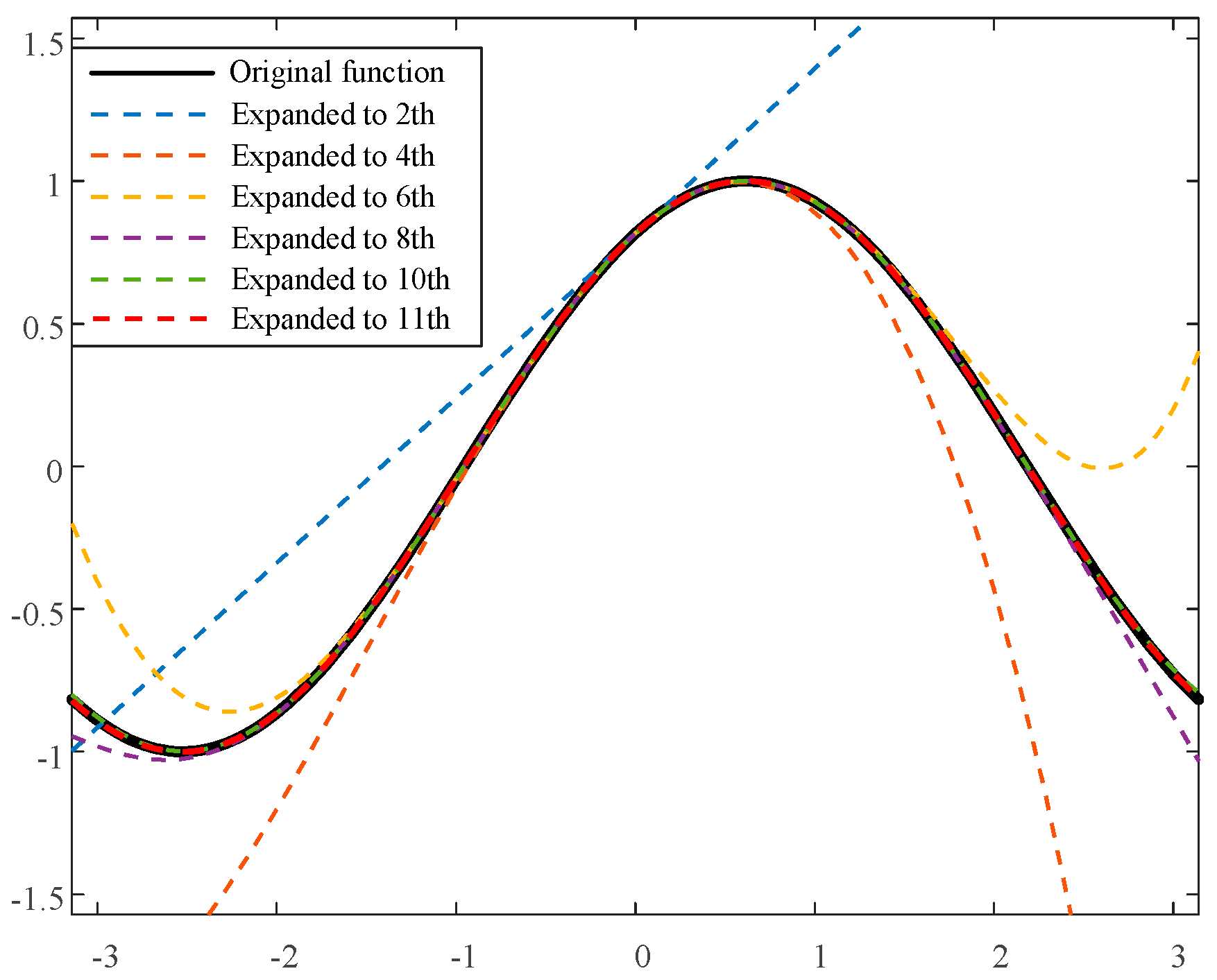
As depicted in Figure 4, after expanding sin(x1 + x1,e) to the 11th order at x1 = 0, the expansion formula coincides with the original function graph. Hence, the sin(x1 + x1,e) can be replaced with the polynomial expanded to the 11th order, as follows:
sin ( x 1 + x 1 , e ) = sin x 1 , e n = 1 6 [ ( 1 ) n 1 x 1 2 n 2 ( 2 n 2 ) ! ] + cos x 1 , e n = 1 6 [ ( 1 ) n 1 x 1 2 n 1 ( 2 n 1 ) ! ]
Given that in practical control, x1 = δ lies within [−π, π], the phase trajectory diagrams before and after the Taylor expansion of Equation (22) are illustrated in Figure 5. It is evident from the figure that the system phase trajectories before and after the Taylor expansion are nearly identical. Therefore, after the Taylor expansion, Equation (22) can be utilized to simulate the original system equations for further analysis.
To corroborate the precision of the reduced-order model, simulations were conducted under the conditions of grid voltage drop, as depicted in Figure 6. Simulations were conducted for scenarios where the grid voltage plummeted from 1 p.u. to 0.5 p.u. (Figure 6a,b, maintaining stability) and from 1 p.u. to 0.4 p.u. (Figure 6c,d, becoming unstable). The simulation results indicate that irrespective of system stability or divergence, the dynamics of x1 and x2 in the reduced-order model consistently align with the dynamics of the full-order model, thereby validating the use of the reduced-order model for further analysis.

3. Transient Stability Analysis of Grid-Connected RPGS

3.1. Construction of LEDA Based on LMI Optimization Method

For a generic polynomial dynamic system, the Lyapunov energy function can be constructed based on the LMI method, and consequently, the LEDA can be derived.
Typically, the Lyapunov energy function can be derived by the following inequations:
A T W + W A < 0 W T = W W > 0
where A is the Jacobian of the polynomial system and W is a positive definite symmetric matrix to be found.
Since matrix W determines the Lyapunov function of the system, which in turn determines the size of the LEDA, the stability analysis problem is transformed into how to choose an appropriate W to make the LEDA as large as possible.
In terms of the Lyapunov stability theorem, the region Ωv = {x ∈ Rn|v(x) ≤ c, c > 0}, determined by a certain Lyapunov function v(x), is the LEDA of the system when the following conditions are satisfied:
Ω v { x R n | v ( x ) g ( x ) < 0 } v ( x ) > 0   a n d   Ω v   is   c o m p a c t
To reduce the complexity of solving Equation (25), if we restrict v(x) to be only of polynomial type, then it is only necessary to satisfy:
p ( x ) > 0 q ( x ) < 0 v ( x ) > 0 , x R n
where p(x) = − q(x)T[∇v(x)Tg(x), cv(x)]T, q(x) is an auxiliary polynomial.
It is found through mathematical derivation that when the following condition is satisfied, Equation (26) holds true:
P ( c , Q , Λ ) + L ( α ) > 0 Q > 0 Λ > 0 t r a c e ( Q 1 ) > 0
where P(c, Q, Λ) + L(α) is the square matrix representation of p(x), Q = diag(Q1, Q2); Λ, Q1, and Q2 are the SMR of v(x), q1(x), and q2(x), respectively; and trace(Q1) represents the trace of matrix Q1.
It has been proven that Ωv is an estimated domain of attraction of the polynomial system when the conditions in Equation (27) are satisfied. We hope to obtain the largest Ωv, that is, LEDA, to reduce its conservativeness. But when v(x) is not quadratic, it is difficult to express the volume of Ωv explicitly. It has been proven that the volume of Ωv can be approximated by (c/trace(Λ))k. So, the LEDA construction of the polynomial system can be transformed into solving the optimization problem in Equation (28):
min ( t r a c e ( Λ ) c ) s . t . P ( c , Q , Λ ) + L ( α ) > 0 Q > 0 Λ > 0 t r a c e ( Q 1 ) > 0
Hence, the LEDA of the system can be derived by using the LMI optimization method to iteratively solve the above equation.

3.2. Analysis of the Correlation of LEDA and System Parameters

The characteristic equation of the RPGS can be derived as:
( 1 k p L g I o d ) λ 2 + ( k p U g cos x 1 , e k i L g I o d ) λ + k i U g cos x 1 , e = 0
It can be found that kpUgcosx1,ekiLgIod represents the damping of the system at the equilibrium point (x1,e, 0), and it is marked by De, which is expressed as Equation (30) according to the definition of x1,e:
D e = k p k i U g cos x 1 , e L g I o d = k p U g 2 ( R g I o q + ω g L g I o d ) 2 k i L g I o d
The influence of the parameters on the system’s transient stability can be obtained by assessing the impact of the parameters on De.
By defining the direction of current flow from the inverter to the grid as positive, Iod > 0 when the inverter operates in inverter mode and Iod < 0 when the inverter operates in rectification mode. This paper only discusses the case where the inverter operates in inverter mode and does not absorb reactive power from the grid. Hence, in the following analysis, it is assumed that Iod ≥ 0 and Ioq ≥ 0. Table 2 shows the changes in damping De and system transient stability when parameters vary, where the direction of the arrow indicates the impact on system damping De and system transient stability when the values of the parameters increase.
It can be seen from Table 2 that increasing kp and Ug, or decreasing ki, Lg, Rg, Iod, and Ioq, can increase system damping and enhance the system’s transient stability. Therefore, in the system design, Ug should be made as large as possible, and Lg and Rg should be made as small as possible, to enhance the system’s transient stability. When the system is given (i.e., Ug, Lg, and Rg are specified), in the controller design process, kp should be made as large as possible and ki as small as possible, while ensuring that the system response meets the required specifications, to enhance the system’s transient stability.

3.3. Verification of the Correlation of LEDA and Parameters

To verify the relationship between system synchronous stability, the LEDA estimation method discussed in Section 3.1 can be used to calculate the LEDA under different system and control parameters.

3.3.1. Line Inductance Lg

Setting the line inductance Lg as 0.3 p.u., 0.4 p.u., and 0.5 p.u., with other parameters kept constant, as shown in Table 1, the LEDA of the system for different Lg values was calculated, as shown in Figure 7. It can be observed that as Lg increases, the maximum allowable angle deviation x1 (δ) between the RPGS and the grid decreases, indicating a reduction in system transient stability, which is consistent with the conclusions in Section 3.2.

3.3.2. Control Parameters of PLL

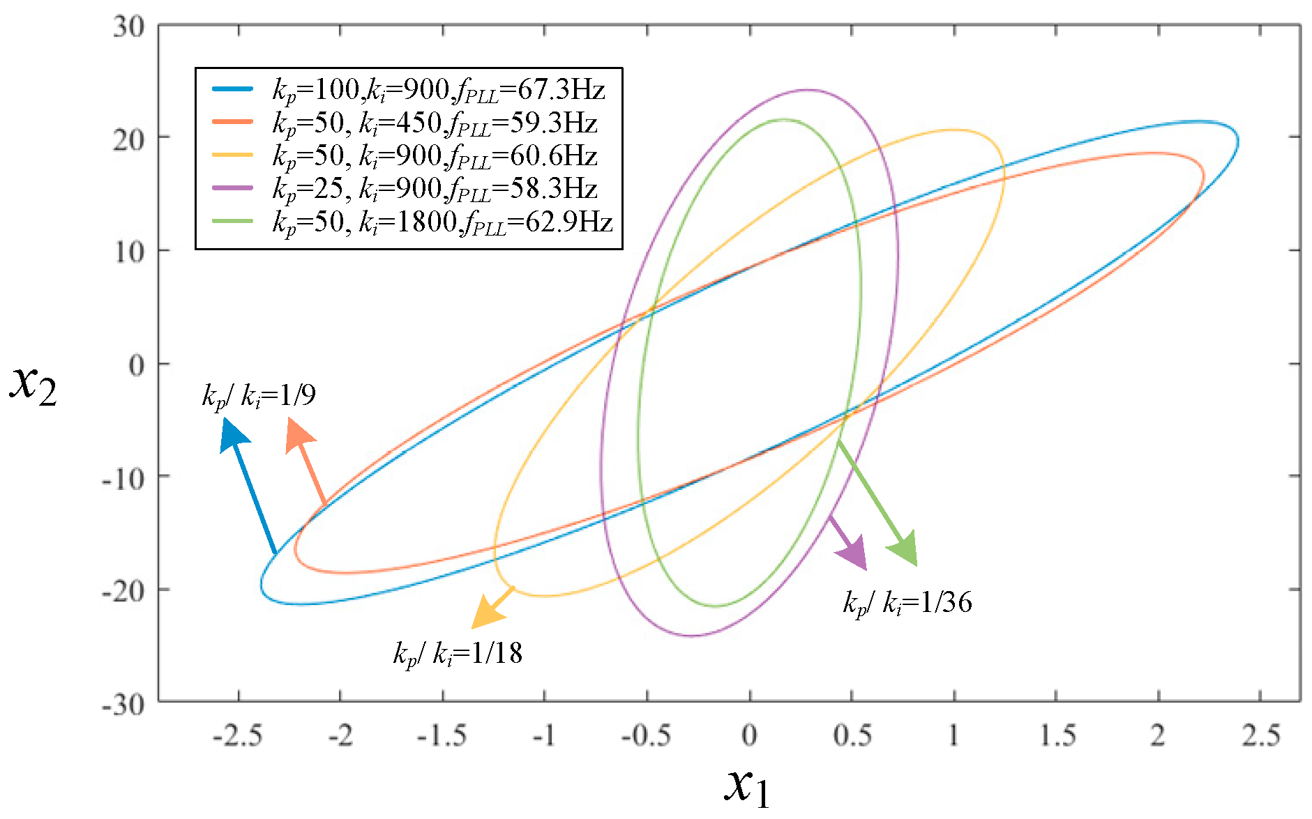
The PLL control parameters kp and ki directly affect the stability of the RPGS. Additionally, the ratio of the proportional coefficient to the integral coefficient kp/ki also affects system stability by influencing the dynamic response of the PLL. Figure 8 shows the LEDA of the system for kp/ki ratios of 1/9, 1/18, and 1/36 (with other parameters unchanging, as indicated in Table 1). From the figure, it can be seen that as kp/ki decreases, the maximum allowable angle deviation x1 (δ) between the RPGS and the grid decreases; when kp/ki is constant, the smaller the values of kp and ki, the smaller the maximum allowable angle deviation x1 (δ) between the RPGS and the grid. In summary, within the range allowed by the system’s dynamic response and parameters, the larger the kp and the smaller the ki, the stronger the system stability, which is consistent with the conclusions in Section 3.2. Additionally, the PLL bandwidths under different PI parameters were calculated. As shown in Figure 8, the relationship between bandwidth and stability is not significant. In summary, the size of the stability region is more closely related to the ratio between the parameters, which aligns with the analysis presented earlier.

3.3.3. Grid Voltage Ug

Setting the grid voltage magnitude Ug as 1 p.u., 0.8 p.u., and 0.6 p.u. (with other parameters not varying, as shown in Table 1), the system’s LEDA for different Ug values was calculated, and the results are shown in Figure 9. From the figure, it can be observed that as the grid voltage decreases, the maximum allowable angle deviation x1 (δ) between the RPGS and the grid decreases, and the system LEDA decreases, indicating a reduction in system stability, which is consistent with the conclusions in Section 3.2.

3.4. Analysis of Feasible Region of Parameters

The system has equilibrium point x1,e when (RgIoq+ ωgLgIod)/Ug ≤ 1. According to the characteristic equation of the system, the system has a stable equilibrium point set when the following inequality holds:
1 k p L g I o d > 0 k p U g cos x 1 , e k i L g I o d > 0 cos x 1 , e > 0
The dynamic equation of the PLL can be written as:
δ ˙ = Δ ω P L L Δ ω ˙ P L L = k i L g I o d k p U g cos δ 1 k p L g I o d Δ ω P L L + k i ( U 0 U g sin δ ) 1 k p L g I o d
Ignoring (kiLgIodkpUgcosδ) ΔωPLL/(1 − kpLgIod) in Equation (32), the following energy function can be constructed:
H e ( δ , Δ ω P L L ) = 1 2 a Δ ω P L L 2 + b ( U 0 δ + U g cos δ ) + c
where a, b, and c are undetermined constants.
The derivative of the energy function He with respect to time is:
H ˙ e = a Δ ω P L L Δ ω ˙ P L L + b ( U 0 U g sin δ ) δ ˙ = a Δ ω P L L ( k i L g I o d k p U g cos δ 1 k p L g I o d Δ ω P L L + k i ( U 0 U g sin δ ) 1 k p L g I o d ) + b ( U 0 U g sin δ ) Δ ω P L L
Setting a = 1 − kpLgIod, b = −ki and c = ki(U0δs +Ugcosδs), where (δs, 0) is the extreme value closest to the origin, the following inequation always holds true.
H e ( δ , Δ ω P L L ) = 1 2 ( 1 k p L g I o d ) Δ ω P L L 2 k i ( U 0 δ + U g cos δ ) + k i ( U 0 δ s + U g cos δ s ) 0 H ˙ e ( δ , Δ ω P L L ) = ( k i L g I o d k p U g cos δ ) Δ ω P L L 2 0
The equal sign is true if and only if δ = δs, ΔωPLL = 0.
Therefore, the feasible region of system and control parameters is derived according to Lyapunov stability theory:
R g I o q + ω g L g I o d < U g k p L g I o d < 1 k i L g I o d k p U g cos δ < 0
Through Equation (36), a three-dimensional graph as shown in Figure 10 can be plotted considering the impact of grid voltage Ug and line inductance Lg. The plane α is drawn by the equation kp = 1/(LgIod), and plane β is drawn by kp = kiLgIod/(Ugcosδ). The region enclosed by kp < plane α and kp > plane β is the stable working area for kp. That is, if the working point of the system determined by the voltage dip depth, line inductance, and PLL proportional coefficient is located below plane α and above plane β, the system can be judged to be stable. Figure 10a,b are three-dimensional surface plots drawn for different PLL integral coefficients ki. It can be seen that when the PLL integral coefficient ki increases, plane β lifts upward. Therefore, the volume of the stable working area enclosed by the two planes decreases, meaning the stable feasible domain of the system parameters decreases and system stability declines.
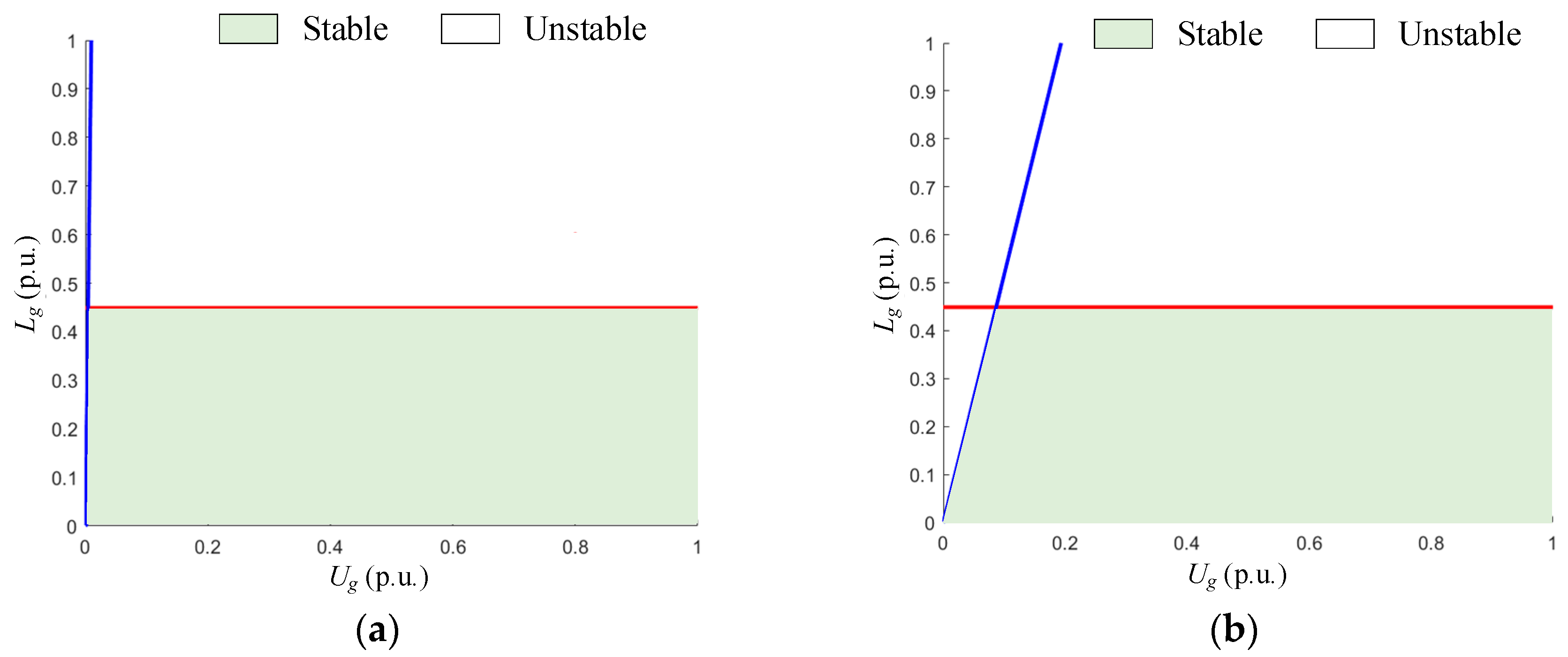
Referring to the 3D graph in Figure 10, by selecting the PLL proportional coefficient kp = 700, the stable and unstable regions of the system parameters can be obtained, as shown in Figure 11. From Figure 11a,b, it can be observed that when the value of the PLL proportional coefficient kp is held constant, for a grid with the same line inductance, the deeper the grid voltage dip, the more likely the system is to become unstable. Similarly, when the degree of grid voltage dip is constant, if the line inductance is smaller (the grid is stronger), the system is less likely to become unstable.

4. Real-Time Simulation Study

To verify the correctness of the proposed analysis method and analysis results, this section analyzes various influencing factors, including different voltage drops, different PI coefficients of PLL kp and ki, different grid line impedances Lg, and different d-axis current reference Iodref, in conjunction with the qualitative analysis method of the parameter feasibility domain presented in Section 3. In the analysis, the HIL simulation model of a 2 MW grid-connected RPGS based on the Typhoon HIL 602 device (Typhoon HIL, Inc., Somerville, MA, USA) is employed to validate the accuracy of the transient stability analysis discussed previously, as shown in Figure 12. The system parameters are given in Table 1.

4.1. HIL Simulation Analysis Under Grid Voltage Drop

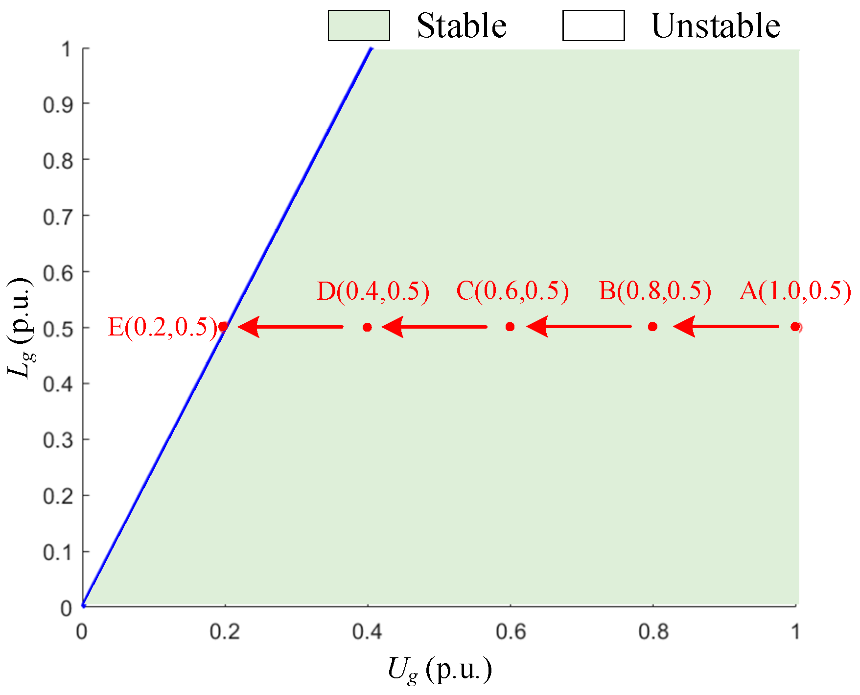
According to the analysis results of system parameters and their correlation with synchronous stability presented in Section 3, it can be observed that, with other parameters held constant, lower grid voltage corresponds to reduced system stability. Therefore, the operational conditions of the system are simulated under varying degrees of voltage sag. The reference current Iodref = 0.6 p.u., kp = 100, and ki = 9000 yield the feasible region of system parameters, as illustrated in Figure 13. The operating points are designated as A → B → C → D → E, where the grid voltage decreases from 1 p.u. to 0.8 p.u., 0.6 p.u., 0.4 p.u., and 0.2 p.u. Based on theoretical analysis, the system maintains stability at operating points A, B, C, and D, while point E is identified as an unstable operating point, resulting in synchronous instability.
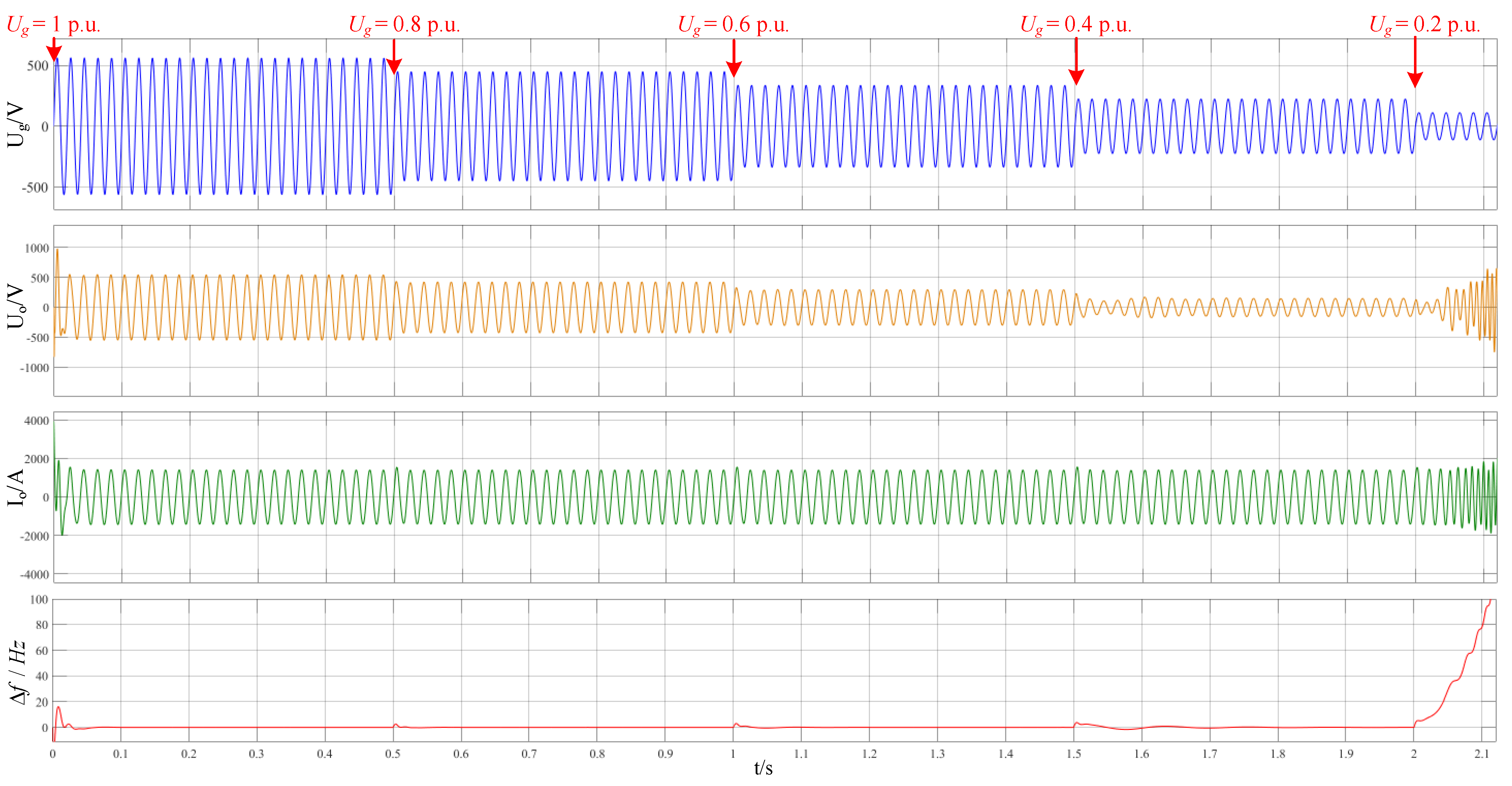
The HIL simulation results, as depicted in Figure 14, indicate that when the grid voltage drops to 0.8 p.u. and 0.6 p.u., the system can quickly track the reference current input. By adjusting the PLL frequency, the RPGS remains synchronized with the grid, leading to rapid stabilization of the grid connection point voltage, thereby achieving stable operation. When the grid voltage decreases to 0.4 p.u., the system experiences slight oscillations at the moment of the voltage drop but ultimately maintains stability. The time required for the grid connection point voltage Uo to stabilize after switching increases, indicating a significant decline in system stability. At a grid voltage of 0.2 p.u., the PLL fails to lock onto the grid phase, resulting in a rapid increase in the PLL angle deviation and leading to synchronous instability, with grid connection point current Io and grid connection point voltage Uo diverging.

4.2. HIL Simulation Analysis of Different PLL Proportional Coefficients

Maintaining the same parameter settings as in Section 4.1, the PLL proportional coefficient kp is set to 50, resulting in the system parameter domain illustrated in Figure 15. It is evident that as kp decreases, the domain of stable system parameters diminishes, transforming the originally stable operating point D (0.4, 0.5) into an unstable operating point, which indicates that the system experiences synchronization instability at point D. The simulation continues with the designated operating points A → B → C → D → E.
The simulation results are presented in Figure 16. It is observed that when the grid voltage drops to 0.8 p.u. and 0.6 p.u., the system is capable of quickly tracking the reference current input and adjusting the PLL frequency, thereby maintaining synchronization between the RPGS and the grid. The voltage at the connection point stabilizes rapidly, enabling stable operation of the system. However, when the grid voltage decreases to 0.4 p.u., oscillations occur in the PLL output, resulting in persistent frequency deviations. Consequently, grid connection point current Io and grid connection point voltage Uo exhibit low-frequency oscillations, leading to system instability. At a grid voltage of 0.2 p.u., the PLL fails to lock onto the grid phase, and the frequency deviation of the PLL escalates rapidly, causing synchronization instability. This results in synchronous instability, causing divergence in grid connection point current Io and grid connection point voltage Uo.

4.3. HIL Simulation Analysis of Different PLL Integral Coefficients

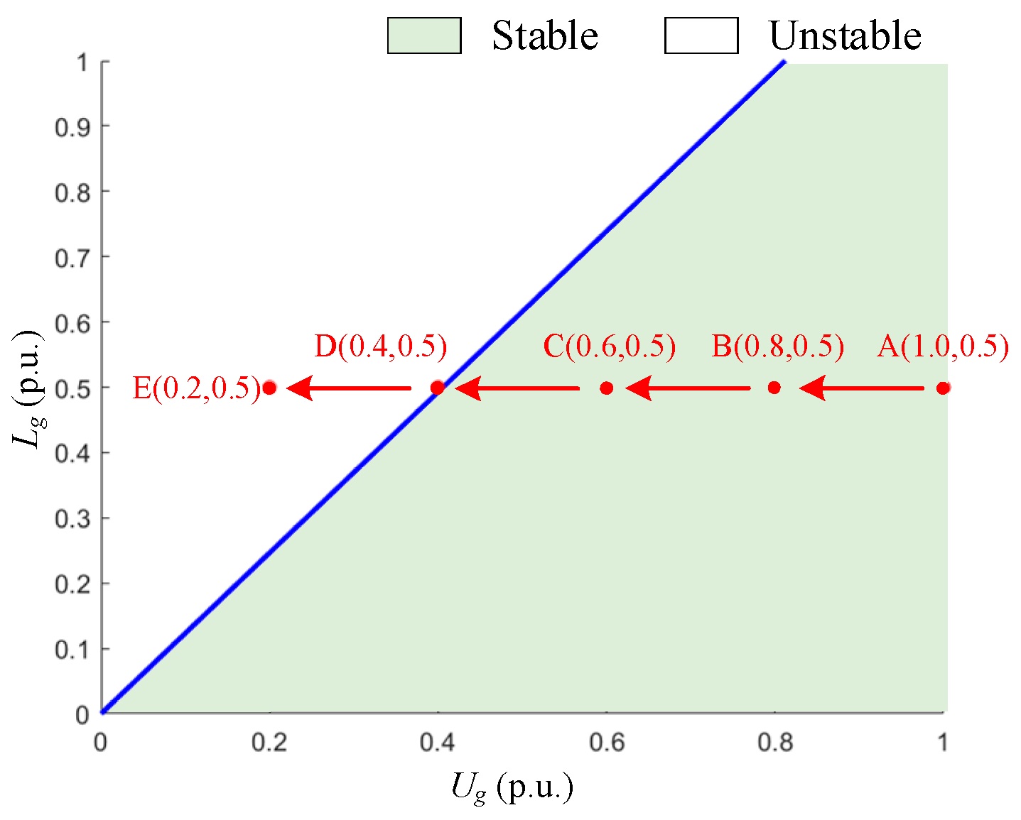
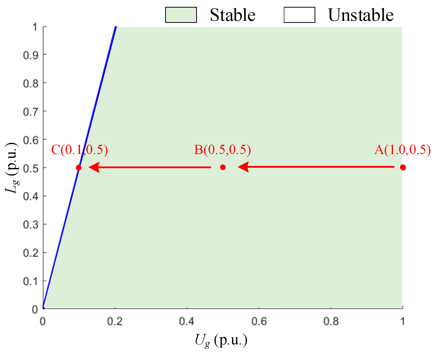
Maintaining the same parameter settings as in Section 4.1, the PLL integral gain ki is set to 50, resulting in the system parameter domain shown in Figure 17. It is evident that a reduction in ki leads to an expansion of the system’s stable parameter domain. The operating points are defined as A → B → C, with the grid voltage dropping from 1 p.u. to 0.5 p.u. and subsequently to 0.1 p.u. According to theoretical analysis, the system remains stable at operating points A and B, while operating point C is identified as unstable, resulting in synchronous instability.
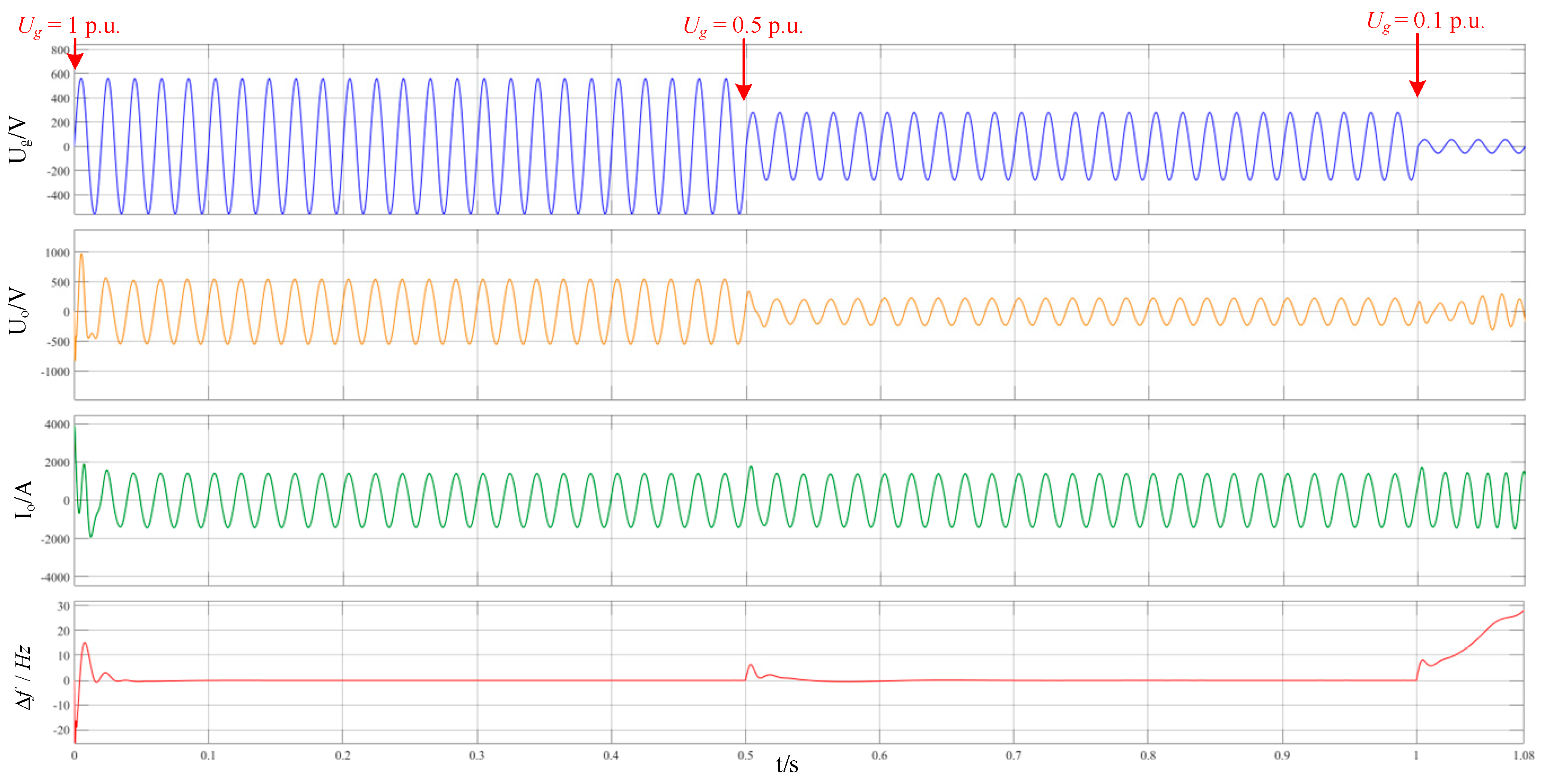
The simulation results are illustrated in Figure 18. When the grid voltage decreases to 0.5 p.u., the system is capable of rapidly tracking the reference current input and adjusting the PLL frequency, thereby maintaining synchronization between the RPGS and the grid. The grid connection point voltage stabilizes quickly, allowing the system to achieve stable operation. However, when the grid voltage falls to 0.1 p.u., the PLL is unable to lock onto the grid phase, leading to a rapid increase in PLL frequency deviation. This results in synchronous instability, causing divergence in grid connection point current Io and grid connection point voltage Uo.

4.4. HIL Simulation Analysis Under Different Grid Line Impedance

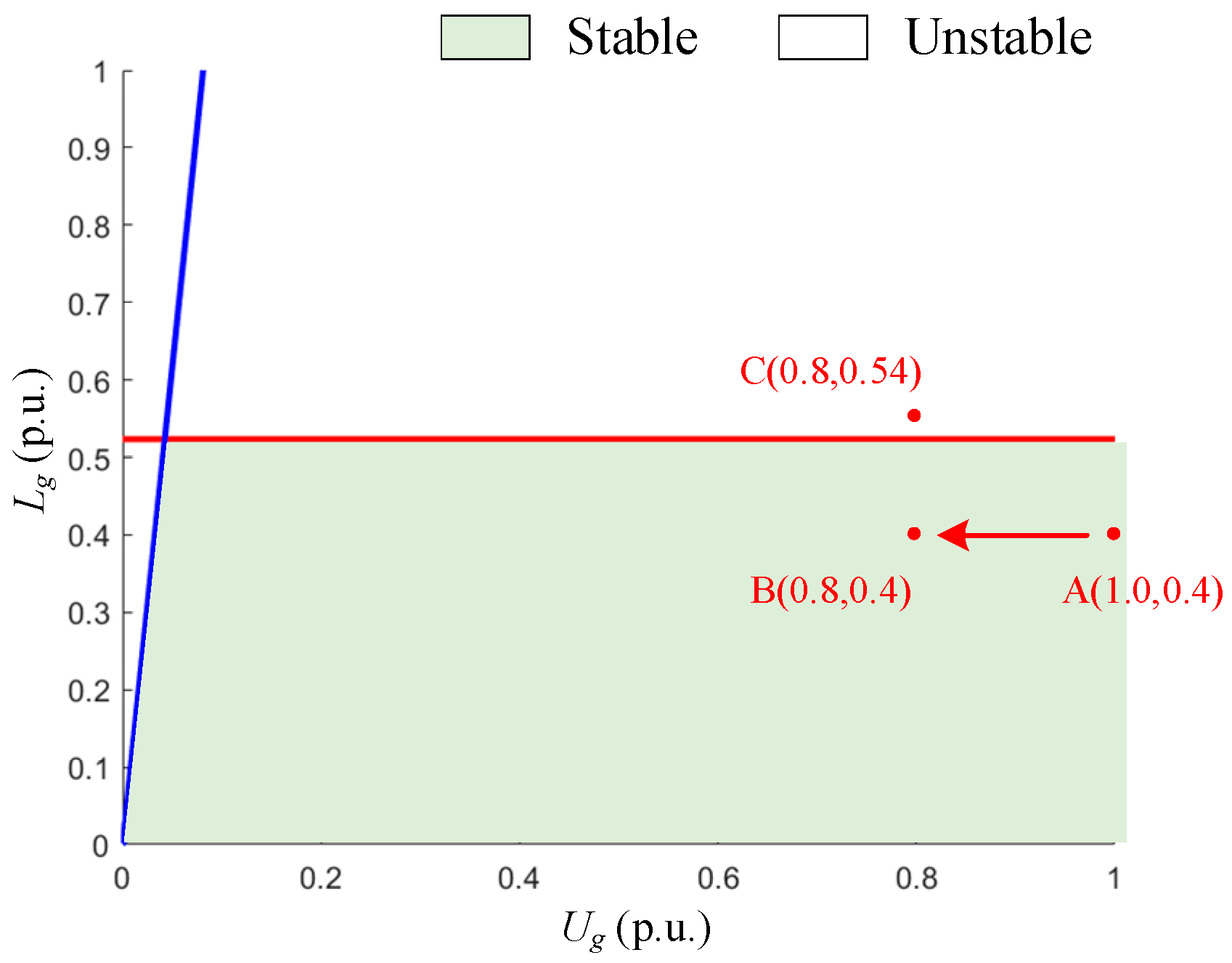
The feasible domain of system parameters after setting Iodref = 0.6 p.u., kp = 1000, and ki = 18,000 is depicted in Figure 19. When the line inductance Lg = 0.4 p.u., the operating points are set from A to B, indicating a voltage drop from the grid voltage of 1 p.u. to 0.8 p.u.; at Lg = 0.54 p.u., the system operates at point C. The theoretical analysis indicates that the system remains stable at both points A and B, while point C is identified as an unstable operating point, leading to synchronized instability.
The simulation results, illustrated in Figure 20a, demonstrate that when the system operates at point A, it can swiftly track the reference current input, and the grid voltage stabilizes rapidly. Transitioning from operating point A to B, where the grid voltage drops to 0.8 p.u., induces oscillations at the moment of voltage drop. Compared to the stabilization process at point A, the duration of stabilization at point B is prolonged, yet the system ultimately maintains stability. As shown in Figure 20b, when operating at point C, the PLL fails to synchronize with the grid phase, resulting in a rapid increase in phase angle deviation, leading to synchronized instability, characterized by divergence in the RPGS port voltage E, grid connection point current Io, and grid connection point voltage Uo.

4.5. HIL Simulation Analysis of Different d-Axis Current References at the Grid Connection Point

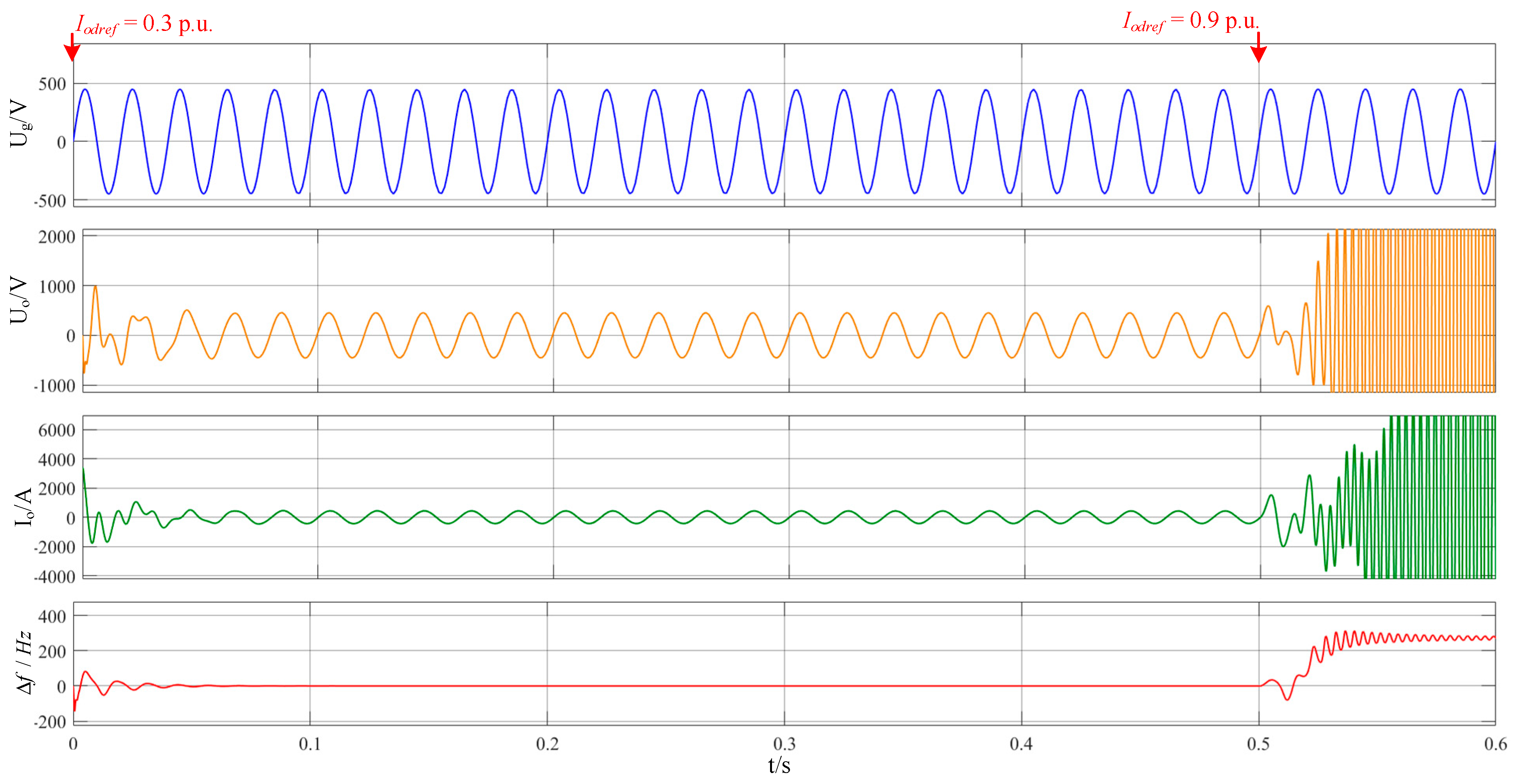
The feasible region for system parameters after setting Lg = 0.6 p.u., kp = 700, and ki = 900 is illustrated in Figure 21. When the d-axis current reference at the grid connection point is established at 0.3 p.u., the operating point A is defined; conversely, when the d-axis current reference is set to 0.9 p.u., the operating point B is established. Theoretical analysis indicates that the system remains stable at operating point A, while operating point B is identified as an unstable state, resulting in synchronous instability.
The HIL simulation results, as shown in Figure 22, demonstrate that when the system operates at point A, it effectively tracks the reference current input, and the grid connection voltage stabilizes quickly. However, when transitioning from operating point A to operating point C, where the d-axis current reference is increased from 0.3 p.u. to 0.9 p.u., the PLL fails to synchronize with the grid phase, leading to a rapid increase in phase angle deviation. Consequently, the system experiences synchronous instability, resulting in divergence of the RPGS grid connection point current Io and grid connection point voltage Uo.
In summary, in-depth simulations are conducted from multiple perspectives, including grid voltage drop, control parameter variation, and system parameter variation, thereby validating the correctness of the proposed method in transient analysis.

5. Conclusions

This study presents a novel approach to analyzing the transient stability of grid-connected inverters. Initially, the dynamics of the PLL and current loop control are incorporated to formulate the state equations based on generator state variables. Non-critical states are eliminated to derive a reduced-order model. Utilizing Lyapunov stability theory, the transient stability analysis is redefined as an estimation problem for the LEDA. A feasible domain-solving algorithm is proposed to investigate the relationship between the LEDA and system parameters under typical operating conditions, revealing instability mechanisms during transient processes. Finally, the HIL simulations conducted in the laboratory verified the effectiveness of the proposed method under various conditions. In particular, the accurate stability assessment of operating points near the selected boundary demonstrated the high precision of the proposed approach. However, the proposed method treats the DC-side output as a stable voltage source. In future research, we will further investigate the impact of the DC voltage response on transient stability analysis, and conduct a more in-depth analysis of the interaction between the RPGS and the grid. In conclusion, the proposed method offers a new perspective for analyzing the stability of RPGSs under system disturbances, laying a theoretical foundation for subsequent controller design and stability enhancement strategies.

Author Contributions

Conceptualization, W.T. and S.H.; methodology, W.T. and S.H.; validation, W.T. and S.H.; formal analysis, W.T. and S.H.; investigation, B.L., X.S. and H.Y.; resources, B.L., X.S. and H.Y.; writing—original draft preparation, B.L., X.S. and H.Y.; writing—review and editing, W.T. and S.H.; visualization, B.L., X.S. and H.Y.; supervision, W.T. and S.H.; project administration, W.T. and S.H.; funding acquisition, W.T., B.L., X.S. and H.Y. All authors have read and agreed to the published version of the manuscript.

Funding

This work is supported by the State Grid Chongqing Economic Research Institute under grant SGTYHT/23-JS-001.

Data Availability Statement

The data used to support the research results of this paper are included within the article.

Conflicts of Interest

The authors declare no conflicts of interest.

Nomenclature

SnRated capacity
UnRated voltage
fnRated frequency
TvFilter time constant
TdController delay
Gd(s)Control delay transfer function
UdcDC-side voltage of the inverter
EPort voltage of the inverter
UoGrid connection point voltage
UgGrid voltage
IoGrid connection point current
ILInductive current
LfInductance of the LC filter
CfCapacitance of the LC filter
RgEquivalent resistance between the grid connection point and the grid
LgEquivalent inductance between the grid connection point and the grid
θPLLPhase angle determined by the PLL
θgGrid phase angle
ΔωDifference between the phase angle of the PLL and the grid
ωPLLPLL angular frequency
ΔωPLLDifference between the angular frequency of the PLL and the grid
ωgGrid angular frequency
fPLLPLL bandwidth
ξDamping ratio of PLL
ωnUndamped natural frequency of PLL
[uod, uoq]dq-Axis components of the output voltage
[ed, eq]dq-Axis components of the current loop output
[Iodref, Ioqref]dq-Axis components of the current loop set values
[igd, igq]dq-Axis components of the grid current
[iod, ioq]dq-Axis components of the output current
[iLd, iLq]dq-Axis components of the filter output current
[kp, ki]PI coefficient of the PLL
[kpc, kic]PI coefficient of the current loop
xfullState variables
AJacobian of the polynomial system
WPositive definite symmetric matrix
DeDamping of the system
HeEnergy function

References

  1. Cepeda, J.C.; Rueda, J.L.; Colomé, D.G.; Echeverría, D.E. Real-time Transient Stability Assessment Based on Centre-of-inertia Estimation from Phasor Measurement Unit Records. IET Gener. Transm. Distrib. 2014, 8, 1363–1376. [Google Scholar] [CrossRef]
  2. Azmy, A.M.; Erlich, I. Impact of Distributed Generation on the Stability of Electrical Power Systems. In Proceedings of the IEEE Power Engineering Society General Meeting, San Francisco, CA, USA, 12 June 2005; pp. 1337–1344. [Google Scholar]
  3. Ndreko, M.; Rüberg, S.; Winter, W. Grid Forming Control Scheme for Power Systems with up to 100% Power Electronic Interfaced Generation: A Case Study on Great Britain Test System. IET Renew. Power Gener. 2020, 14, 1268–1281. [Google Scholar]
  4. Poulose, A.; Kim, S. Transient Stability Analysis and Enhancement Techniques of Renewable-Rich Power Grids. Energies 2023, 16, 2495. [Google Scholar] [CrossRef]
  5. Zhang, Q.; Mao, M.; Ke, G.; Zhou, L.; Xie, B. Stability Problems of PV Inverter in Weak Grid: A Review. IET Power Electron. 2020, 13, 2165–2174. [Google Scholar] [CrossRef]
  6. Tian, X.; Zhang, Y.; Xu, Y.; Zheng, L.; Zhang, L.; Yuan, Z. Transient Synchronous Stability Modeling and Comparative Analysis of Grid-Following and Grid-Forming New Energy Power Sources. Electronics 2024, 13, 3308. [Google Scholar] [CrossRef]
  7. Sajadi, A.; Rañola, J.A.; Kenyon, R.W.; Hodge, B.-M.; Mather, B. Dynamics and Stability of Power Systems with High Shares of Grid-Following Inverter-Based Resources: A Tutorial. IEEE Access 2023, 11, 29591–29613. [Google Scholar]
  8. Song, J.; Zhou, X.; Zhou, Z.; Wang, Y.; Wang, Y.; Wang, X. Review of Low Inertia in Power Systems Caused by High Proportion of Renewable Energy Grid Integration. Energies 2023, 16, 6042. [Google Scholar] [CrossRef]
  9. Du Plessis, A.A.; Strauss, J.M.; Rix, A.J. Short-term solar power forecasting: Investigating the ability of deep learning models to capture low-level utility-scale Photovoltaic system behaviour. Appl. Energy 2021, 285, 116395. [Google Scholar] [CrossRef]
  10. Hong, L.; Tang, R.; Jiang, Q.; Xie, X.; Zhu, Y. Admittance-Based Stability Analysis of LCL-type Grid-connected Inverter Considering AC-side and AC-DC Frequency Coupling Effects. IEEE Trans. Power Deliv. 2024, 39, 1351–1363. [Google Scholar]
  11. Ding, N.; Lu, Z.; Qiao, Y.; Min, Y. Simplified equivalent models of large-scale wind power and their application on small-signal stability. J. Mod. Power Syst. Clean Energy 2013, 1, 58–64. [Google Scholar] [CrossRef]
  12. Patrao, I.; Liberos, M.; González-Medina, R.; Torán, E.; Figueres, E.; Garcerá, G. Small-Signal Model of the NPC+ GCC Multilevel Transformerless Inverter in Single-Phase Photovoltaic Power Systems. Electronics 2023, 12, 3545. [Google Scholar] [CrossRef]
  13. Zhang, R.; Zhang, C.; Xing, X.; Chi, S.; Liu, C.; Fang, J. Modeling and attenuation of common mode resonance current for improved LCL-type parallel inverters in PV plants. IEEE Trans. Ind. Inform. 2023, 20, 5193–5205. [Google Scholar] [CrossRef]
  14. Wang, F.; Feng, X.; Zhang, L.; Du, Y.; Su, J. Impedance-based analysis of grid harmonic interactions between aggregated flyback micro-inverters and the grid. IET Power Electron. 2018, 11, 453–459. [Google Scholar] [CrossRef]
  15. Zhou, W.; Torres-Olguin, R.E.; Wang, Y.; Chen, Z. A gray-box hierarchical oscillatory instability source identification method of multiple-inverter-fed power systems. IEEE J. Emerg. Sel. Top. Power Electron. 2020, 9, 3095–3113. [Google Scholar] [CrossRef]
  16. Chen, Q.; Bu, S.; Chung, C.Y. Small-Signal Stability Criteria in Power Electronics-Dominated Power Systems: A Comparative Review. J. Mod. Power Syst. Clean Energy 2024, 12, 1003–1018. [Google Scholar]
  17. Mazumder, S.K.; Acharya, K. Multiple Lyapunov Function Based Reaching Condition for Orbital Existence of Switching Power Converters. IEEE Trans. Power Electron. 2008, 23, 1449–1471. [Google Scholar] [CrossRef]
  18. Ilić, M.D.; Xie, L.; Khan, U.A.; Moura, J.M.F. Modeling of Future Cyber–Physical Energy Systems for Distributed Sensing and Control. IEEE Trans. Syst. Man Cybern. Part A Syst. Hum. 2010, 40, 825–838. [Google Scholar] [CrossRef]
  19. Kim, H.-S.; Jung, H.-S.; Sul, S.-K. Discrete-Time Voltage Controller for Voltage Source Converters with LC Filter Based on State-Space Models. IEEE Trans. Ind. Appl. 2019, 55, 529–540. [Google Scholar] [CrossRef]
  20. Pan, D.; Wang, X.; Liu, F.; Shi, R. Transient Stability of Voltage-Source Converters with Grid-Forming Control: A Design-Oriented Study. IEEE J. Emerg. Sel. Top. Power Electron. 2020, 8, 1019–1033. [Google Scholar] [CrossRef]
  21. Taul, M.G.; Wang, X.; Davari, P.; Blaabjerg, F. Systematic Approach for Transient Stability Evaluation of Grid-Tied Converters during Power System Faults. In Proceedings of the 2019 IEEE Energy Conversion Congress and Exposition (ECCE), Baltimore, MD, USA, 29 September–3 October 2019; pp. 5191–5198. [Google Scholar]
  22. Reza, M.; Sudarmadi, D.; Viawan, F.A.; Kling, W.L.; Van Der Sluis, L. Dynamic Stability of Power Systems with Power Electronic Interfaced DG. In Proceedings of the 2006 IEEE PES Power Systems Conference and Exposition, Atlanta, GA, USA, 29 October 2006–1 November 2006; pp. 1423–1428. [Google Scholar]
  23. Khalil, H.K. Nonlinear Systems, 3rd ed.; Prentice Hall: Upper Saddle River, NJ, USA, 2002. [Google Scholar]
  24. Ma, R.; Li, J.; Kurths, J.; Cheng, S.; Zhan, M. Generalized Swing Equation and Transient Synchronous Stability with PLL-Based RPGS. IEEE Trans. Energy Convers. 2022, 37, 1428–1441. [Google Scholar] [CrossRef]
  25. Shakerighadi, B.; Ebrahimzadeh, E.; Blaabjerg, F.; Leth Bak, C. Large-Signal Stability Modeling for the Grid-Connected RPGS Based on the Lyapunov Method. Energies 2018, 11, 2533. [Google Scholar] [CrossRef]
  26. Goksu, O.; Teodorescu, R.; Bak, C.L.; Iov, F.; Kjaer, P.C. Instability of Wind Turbine Converters During Current Injection to Low Voltage Grid Faults and PLL Frequency Based Stability Solution. IEEE Trans. Power Syst. 2014, 29, 1683–1691. [Google Scholar] [CrossRef]
  27. Lamarque, C.-H.; Touzé, C.; Thomas, O. An Upper Bound for Validity Limits of Asymptotic Analytical Approaches Based on Normal Form Theory. Nonlinear Dyn. 2012, 70, 1931–1949. [Google Scholar] [CrossRef]
  28. Fotopoulou, M.; Rakopoulos, D.; Petridis, S.; Drosatos, P. Assessment of smart grid operation under emergency situations. Energy 2024, 287, 129661. [Google Scholar] [CrossRef]
  29. Edrah, M.; Lo, K.L.; Anaya-Lara, O. Impacts of High Penetration of DFIG Wind Turbines on Rotor Angle Stability of Power Systems. IEEE Trans. Sustain. Energy 2015, 6, 759–766. [Google Scholar] [CrossRef]
  30. Taul, M.G.; Wang, X.; Davari, P.; Blaabjerg, F. An Overview of Assessment Methods for Synchronization Stability of Grid-Connected Converters Under Severe Symmetrical Grid Faults. IEEE Trans. Power Electron. 2019, 34, 9655–9670. [Google Scholar] [CrossRef]
  31. Kabalan, M.; Singh, P.; Niebur, D. Large Signal Lyapunov-Based Stability Studies in Microgrids: A Review. IEEE Trans. Smart Grid 2017, 8, 2287–2295. [Google Scholar] [CrossRef]
  32. Shair, J.; Li, H.; Hu, J.; Xie, X. Power System Stability Issues, Classifications and Research Prospects in the Context of High-Penetration of Renewables and Power Electronics. Renew. Sustain. Energy Rev. 2021, 145, 111111. [Google Scholar] [CrossRef]
  33. Zhang, Y.; Zhang, C.; Cai, X.; Qiu, W.; Zhao, X. Transient Grid-synchronization Stability Analysis of Grid-tied Voltage Source Converters: Stability Region Estimation and Stabilization Control. Proc. CSEE 2022, 42, 7871–7884. [Google Scholar]
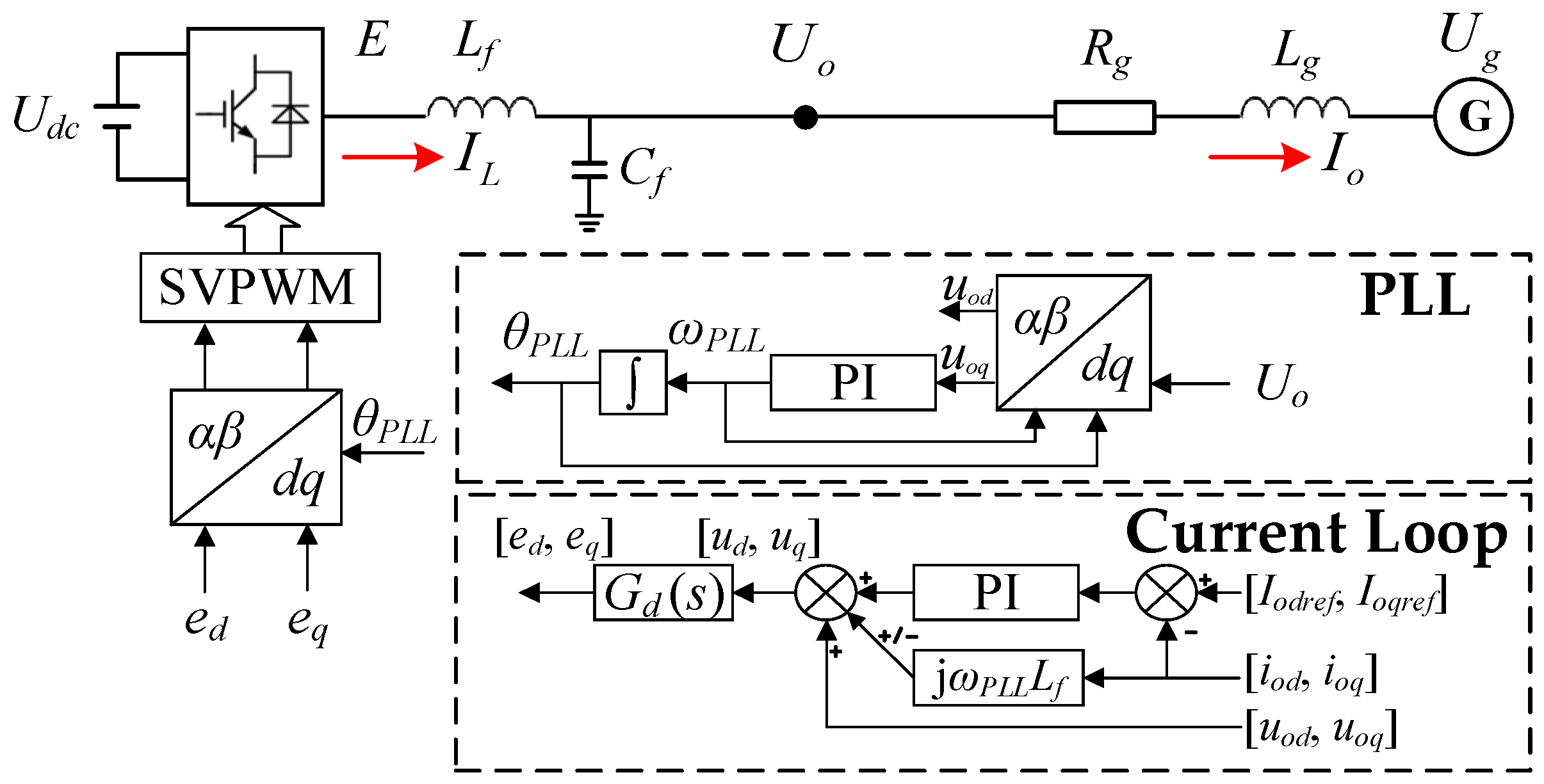
Figure 1. Structure diagram of the grid-connected inverter.
Electronics 13 05052 g001
Figure 2. Control structure diagram of the PLL.
Electronics 13 05052 g002
Figure 3. Equivalent control structure diagram.
Electronics 13 05052 g003
Figure 4. The sin(x1 + x1,e) and its Taylor expansion.
Electronics 13 05052 g004
Figure 5. The sin(x1 + x1,e) and its Taylor expansion. (a) Phase trajectory diagram before expansion; (b) phase trajectory diagram after expansion.
Electronics 13 05052 g005
Figure 6. Comparative simulation graph of full-order and reduced-order models: (a) waveform of x1 when Ug drops from 1 p.u. to 0.5 p.u.; (b) waveform of x2 when Ug drops from 1 p.u. to 0.5 p.u.; (c) waveform of x1 when Ug drops from 1 p.u. to 0.4 p.u.; (d) waveform of x2 when Ug drops from 1 p.u. to 0.4 p.u.
Electronics 13 05052 g006
Figure 7. LEDA under different Lg.
Electronics 13 05052 g007
Figure 8. LEDA under different kp/ki.
Electronics 13 05052 g008
Figure 9. LEDA under different Ug.
Electronics 13 05052 g009
Figure 10. A 3D diagram of critical values of kp under different Ug and Lg: (a) ki = 900; (b) ki = 18,000.
Electronics 13 05052 g010
Figure 11. Stable and unstable region under kp = 700, ki = 900: (a) ki = 900; (b) ki = 18,000.
Electronics 13 05052 g011
Figure 12. Real-time simulation platform.
Electronics 13 05052 g012
Figure 13. Working point setting for simulation analysis under grid voltage drop.
Electronics 13 05052 g013
Figure 14. HIL simulation results of simulation analysis under grid voltage drop.
Electronics 13 05052 g014
Figure 15. Working point setting for simulation analysis of different PLL proportional coefficients.
Electronics 13 05052 g015
Figure 16. Simulation results of the simulation analysis of different PLL proportional coefficients.
Electronics 13 05052 g016
Figure 17. Working point setting for simulation analysis of different PLL integral coefficients.
Electronics 13 05052 g017
Figure 18. Simulation results of simulation analysis of different PLL integral coefficients.
Electronics 13 05052 g018
Figure 19. Working point setting for simulation analysis under different grid line impedance.
Electronics 13 05052 g019
Figure 20. Simulation results of simulation analysis under different grid line impedance: (a) working points A and B; (b) working point C.
Electronics 13 05052 g020
Figure 21. Working point setting for simulation analysis of different d-axis current references at the grid connection point: (a) Iodref = 0.3 p.u.; (b) Iodref = 0.9 p.u.
Electronics 13 05052 g021
Figure 22. Simulation results of simulation analysis of different d-axis current references at the grid connection point.
Electronics 13 05052 g022
Table 1. Principal system parameters.
System ParametersActual Value/
Per Unit Value (p.u.)
Control ParametersActual Value/
Per Unit Value (p.u.)
Rated capacity Sn2 MW/1d-Axis current reference Iodref2367 A/1
Rated voltage Un 0.69 kV/1 q-Axis current reference Ioqref0 A/0
Rated frequency fn50 HzPI coefficient of PLL kp: 0.09/50
ki: 1.6/900
Filter inductance Lf 0.076 mH/0.1PI coefficient of current loop kpc: 0.165/0.4
kic: 1.65/4
Filter capacitance Cf 535 μF/0.04Filter time constant Tv 1 ms
Line inductance Lg 0.3 mH/0.4Controller delay Td 200 μs
Table 2. Qualitative influence of system parameters on synchronization stability.
ParameterDescriptionSystem Damping DeTransient
Stability
kpProportional coefficient of PLL↑ (De increase)↑ (Stability increase)
kiIntegral coefficient of PLL↓(De decrease)↓ (Stability decrease)
UgGrid voltage
LgLine impedance
IodrefCurrent reference on d-axis
IoqrefCurrent reference on q-axis
Disclaimer/Publisher’s Note: The statements, opinions and data contained in all publications are solely those of the individual author(s) and contributor(s) and not of MDPI and/or the editor(s). MDPI and/or the editor(s) disclaim responsibility for any injury to people or property resulting from any ideas, methods, instructions or products referred to in the content.