3.2. Data Analysis
As shown in
Figure 5, the sensor data for a complete cycle can be divided into four parts. Since the train does not operate continuously for 24 h but the sensor collects data throughout the entire day, analyzing this full-day data set allows us to accurately identify the specific time periods we need to predict and determine which parameters will be used to forecast abnormal conditions.
The data of S1 segment are from 00:00 to 03:00. As shown in the figure, the train running speed is 0, and the train remains in an inactive state during this period. At this time, the temperature of the motor bearings and stator is mainly affected by the external environment, and the basic trend changes with the change of external temperature.
The data for segment S2 are from 03:00 to 05:00, during which the train speed fluctuates twice. This stage is mainly the testing phase before the train runs, and the temperature of the motor bearings and stator fluctuates slightly due to the influence of train speed. At this time, the temperature of the motor bearings is more affected by the ambient temperature compared to the stator temperature, but it may also fluctuate due to the train starting. During the phase of increasing train speed, the values of various temperature sensors of the motor change.
The data of S3 segment are from 05:00 to 21:00, which is the stage of train operation. The sensors are affected by the running speed and ambient temperature. When stopping at the station, if t is 690 and the train speed is 0, the axle temperature and stator sensor temperature will have a decreasing trend over time.
The data for S4 segment are from 21:10–24:00. At this time, the train stops at the station with a running speed of 0. The temperature of the motor bearings and stator gradually approaches room temperature. After a period of time, like S1 segment, it is mainly affected by the external environment.
After dividing the train operation phase into four sections, the correlation between each parameter in each section will be analyzed in detail.
This article uses methods such as correlation coefficient, scatter plot, and correlation coefficient table to analyze the correlation between the data. The use of matrix scatter plots can visually display the relationships between variables and help us further understand the distribution of data. The correlation coefficient table provides detailed correlation information, which helps screen parameters and prepare for predicting the temperature of traction motors in the future.
Figure 5 shows the segmentation results of data from a certain day in August.
In this article, the Pearson correlation coefficient is used to calculate the correlation between various parameters.
- (1)
S1 and S2 segments:
Due to the fact that the S1 and S2 segments are mainly affected by environmental temperature and are not significantly affected by other temperatures, they were analyzed together. From the matrix scatter plot and correlation coefficient graph in
Figure 6, it can be seen that the linear relationship between the parameters in this segment is not strong. There is a certain correlation between the stator, drive-end, and non-drive-end bearing temperatures of the traction motor. The reason may be that all three parameters are affected by outdoor temperature during this stage, so the trend of change is roughly the same. The correlation coefficient between train speed and motor current is relatively large, but the linear correlation is not obvious. At this stage, the train has not yet started running, so it is impossible to accurately determine the precise relationship between various factors.
- (2)
S3 segment:
From the matrix scatter plot and correlation coefficient graph in
Figure 7, it can be seen that there is a linear correlation and strong correlation between the stator, drive-end bearing, and non-drive-end bearing temperatures of the traction motor. The reason may be that all three parameters are greatly affected by speed during this stage, and their trend changes with speed. The correlation coefficient between the external temperature and non-drive-end bearing temperature during this stage is relatively large, and the temperature of the non-drive-end bearing may be more affected by external temperature than the temperature of the drive-end bearing. The stator may be affected by external temperature.
- (3)
S4 section:
From the matrix scatter plot and correlation coefficient graph in
Figure 8, it can be seen that some parameters have a clear linear relationship with time. There is a strong correlation between the temperature and time of the stator, drive-end bearing, and non-drive-end bearing of the traction motor. The reason may be that at this stage, when the train stops at the station, the temperature of the motor gradually decreases to the outdoor temperature, so there is a negative correlation with time.
As can be seen from the sections above, the time when the traction motor experiences temperature abnormalities is generally in section S3, which is the stage of train operation, and may be affected by various factors that may cause abnormal temperature of the traction motor, thereby affecting its state. Therefore, the data from section S3 will be selected for subsequent prediction.
3.3. Method Validation
In order to verify the feasibility and accuracy of the algorithm in this paper, the high-speed train data set in
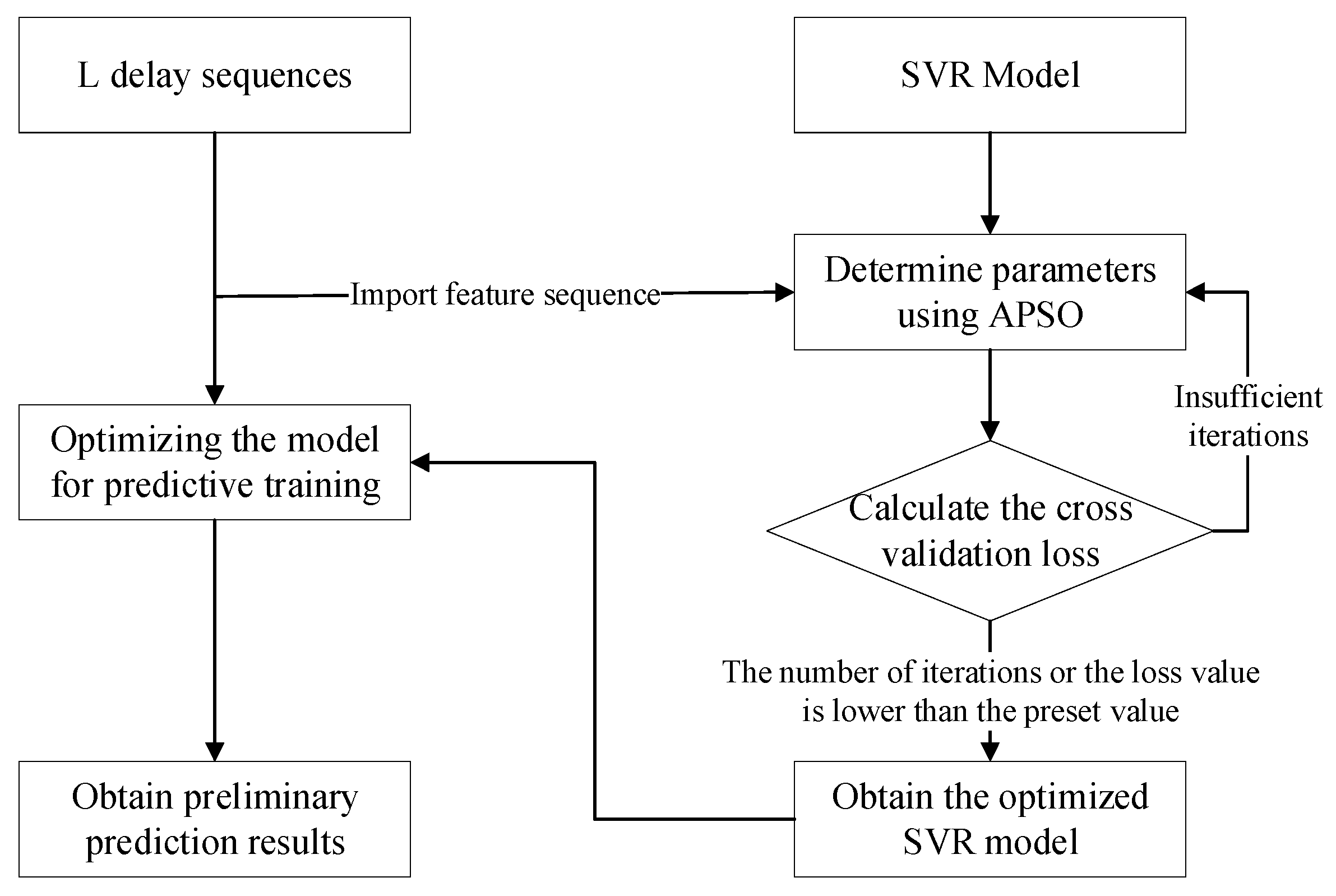
Section 2.1 was divided into a training set and a test set according to a ratio of 7:3. The influence of external and internal factors on the state of the traction motor was considered. Time, external temperature, train speed, and initial bearing temperature of the traction motor were selected as inputs to verify the algorithm in this paper. First, the data shown in
Table 3 were used to construct the time-delayed sequences, as shown in
Figure 9.
A time-delayed sequence was constructed for each input parameter of the traction motor, and the MIC value was calculated in relation to the target signal. Here, the temperature signal of the traction motor drive-end was taken as the target temperature signal. The calculated partial MIC value results are shown in
Table 4. It can be seen that the MIC value of time is the largest, followed by the external temperature, train speed, and the initial bearing temperature of the traction motor.
Equations (13)–(18) provide the calculation methods for the mean square error
, root mean square error
, mean absolute error
, mean bias error
, mean absolute percentage error
, and
, and the results of calculating the parameters above based on the predicted values of the traction motor temperature and its true values are shown in
Table 5.
where
is the number of prediction samples,
is the true value,
is the predicted value,
is the variation explained by the regression model, and
is the total variation of the dependent variable.
The residual prediction result using KNN is shown in
Figure 10, and the final prediction result of the prediction method based on MIC and improved SVR is shown in
Figure 11.
From the residual prediction results of KNN in
Figure 10, it can be seen that the predicted value has the same positive and negative signs as the true value. Using KNN for residual prediction can reduce some prediction errors. From
Figure 11, it can be seen that after prediction using the method proposed in this paper, the predicted value of the traction motor temperature signal output is closer to its true temperature value, and when the temperature fluctuates, the method in this paper can still make predictions, and the model fitting effect is good.


