Article

A Triboelectric Nanogenerator Utilizing a Crank-Rocker Mechanism Combined with a Spring Cantilever Structure for Efficient Energy Harvesting and Self-Powered Sensing Applications

1
College of Mechanical & Energy Engineering, Beijing University of Technology, Beijing 100124, China
2
School of Intelligent Engineering and Automation, Beijing University of Posts and Telecommunications, Beijing 100876, China
*
Author to whom correspondence should be addressed.
Electronics 2024, 13(24), 5032; https://doi.org/10.3390/electronics13245032
Submission received: 14 November 2024 / Revised: 19 December 2024 / Accepted: 19 December 2024 / Published: 21 December 2024

Abstract

:
With the advancement of industrial automation, vibrational energy generated by machinery during operation is often underutilized. Developing efficient devices for vibration energy harvesting is thus essential. Triboelectric nanogenerators (TENGs) based on spring and cantilever beam structures show considerable potential for industrial vibration energy harvesting; however, traditional designs often fail to fully harness vibrational energy due to their structural limitations. This study proposes a triboelectric nanogenerator (TENG) based on a crank-rocker mechanism and a spring cantilever structure (CR-SC TENG), which combines a crank-rocker mechanism with a spring cantilever structure, designed for both energy harvesting and self-powered sensing. The CR-SC TENG incorporates a spring cantilever beam, a crank-rocker mechanism, and lever amplification principles, enabling it to respond sensitively to low-frequency, small-amplitude vibrations. Utilizing the crank-rocker and lever effects, this device significantly amplifies micro-amplitudes, enhancing energy capture efficiency and making it well suited for low-amplitude, complex industrial environments. Experimental results demonstrate that this design effectively amplifies micro-vibrations and markedly improves energy conversion efficiency within a frequency range of 1–35 Hz and an amplitude range of 1–3 mm. As a sensor, the CR-SC TENG’s dual-generation units produce output signals that precisely reflect vibration frequencies, making it suitable for the intelligent monitoring of industrial equipment. When placed on an air compressor operating at 25 Hz, the first-generation unit achieved an output voltage of 150 V and a current of 8 μA, while the second-generation unit produced an output voltage of 60 V and a current of 5 μA. These findings suggest that the CR-SC TENG, leveraging spring cantilever beams, crank-rocker mechanisms, and lever amplification, has significant potential for micro-amplitude energy harvesting and could play a key role in smart manufacturing, intelligent factories, and the Internet of Things.

1. Introduction

With the rapid advancement of industrial modernization, global energy consumption continues to rise, with machinery operation representing a significant portion of this demand [1,2]. For instance, industrial air compressors, while achieving motor efficiencies of approximately 90%, still lose around 5–10% of electrical energy due to random mechanical vibrations and noise [3,4]. These low-frequency vibrations, generally below 100 Hz, are difficult for conventional electromagnetic generators to capture and utilize efficiently [5]. Indeed, inefficient energy loss is common across industrial machinery, including air compressors, and has become a major barrier to energy conservation and emissions reduction in China’s industrial sector [6]. Therefore, developing technologies that can recover this low-grade mechanical vibrational energy and transform it from “energy waste to energy reuse” is essential to fostering sustainable development [7,8]. The primary goal of capturing these random vibrations is to provide power for small electronic devices or sensor nodes, replacing traditional batteries—especially in situations where battery replacement is challenging or where operating environments are specialized [9,10,11,12]. To convert mechanical vibrations from the environment into usable electrical energy, researchers have explored various physical mechanisms, such as electromagnetic and piezoelectric effects. However, energy harvesters based on electrostatic effects tend to be bulky, expensive, and ill-suited for capturing low-frequency vibrations [13,14]. Although piezoelectric energy harvesters can operate at low frequencies, their inherent material properties limit their power density and efficiency, making substantial performance improvements difficult [15,16,17]. Therefore, enhancing the performance of vibration energy harvesting devices remains a critical objective in advancing industrial smart manufacturing and intelligent monitoring.
The triboelectric nanogenerator (TENG) [18] is an innovative energy generation technology based on triboelectric and electrostatic induction principles. With its simple structure, high output voltage, and wide response bandwidth, TENG has found extensive applications in the field of random vibration energy harvesting [19,20,21]. However, TENGs generally require a substantial contact separation distance to achieve optimal output, which limits their applicability in small-amplitude vibration scenarios [22]. Additionally, existing TENG designs are often complex and costly to manufacture, making large-scale commercialization challenging. Moreover, TENGs’ high impedance and mismatched load characteristics limit their ability to efficiently power electronic components directly [21]. Therefore, enhancing the efficiency of current TENG technology in vibration energy harvesting and conversion is especially critical. In this regard, cantilever beam structures, which are fixed at one end with a mass attached to the other, have shown potential due to their effective response to vibrational deformations in operating equipment [23,24,25]. For instance, Weiqing Yang et al. [26] developed a TENG with a three-cantilever beam structure, applying a PDMS film to the bottom layer of the top cantilever and the inner surface of the bottom cantilever, while the upper and lower surfaces of the middle cantilever were coated with ZnO nanowires and a copper film, with an additional mass to improve response sensitivity. Under external vibrational excitation, the middle cantilever undergoes contact and separation with the upper and lower cantilevers, generating triboelectric charges. Each vibration cycle contains two contact separation events, significantly enhancing the TENG’s output power. Experimental results showed that this design achieved an open-circuit voltage of approximately 101 V, a short-circuit current of 55.7 μA, and a peak power density of 252.3 mW/m2. Likewise, Gang Tang et al. [27] designed a two-degree-of-freedom cantilever beam vibration energy harvester, with PDMS and aluminum films as the positive and negative triboelectric materials, respectively, and successfully applied it to vibration energy harvesting in a vacuum compressor, achieving an open-circuit voltage output of up to 8 V. Zewei Ren et al. [28] proposed a trapezoidal cantilever-structured TENG(C-TENG), using aluminum electrodes and a FEP layer on flexible PET film as the triboelectric materials. This C TENG was capable of harvesting low-frequency vibration sources as low as 1 Hz, achieving a power density output of 62.2 W/m3 at 5 Hz.
To further enhance sensitivity and output performance, this paper presents a novel triboelectric nanogenerator that integrates a crank-rocker mechanism [29] with a spring cantilever beam [30] and lever amplification principles [31]. In this TENG structure, the spring cantilever beam significantly increases the system’s elasticity and sensitivity, utilizing elastic deformation at the fixed end to respond to weak external vibrations. Additionally, this design effectively incorporates the mechanical characteristics of the crank-rocker mechanism to amplify vibration input through the lever amplification principle, allowing stable electrical output even under small vibrations and substantially improving energy conversion efficiency. In this design, the crank-rocker mechanism transfers the motion of the spring cantilever beam to the lever, driving its rotation to precisely capture and amplify minor vibrations. This combined design not only enhances energy conversion efficiency but also achieves high electrical output under low excitation, demonstrating promising applications in vibration energy harvesting within low-frequency, low-amplitude environments, such as industrial equipment vibration recovery and self-powered environmental monitoring systems. As a self-powered vibration sensor, the CR-SC TENG further enables fault monitoring for electromechanical equipment. Currently, common electromagnetic or piezoelectric vibration energy harvesting devices have limitations when used as sensors. Electromagnetic sensors are susceptible to interference from metallic structures in electromechanical equipment, complicating the installation process. Additionally, their low signal amplitude results in reduced sensitivity. Similarly, piezoelectric sensors produce relatively low signal amplitudes, often requiring signal amplification and more complex materials and structures. In contrast, the CR-SC TENG, with its high signal-to-noise ratio electrical output, demonstrates superior vibration sensing capabilities and unique energy potential.

2. Results and Discussion

2.1. Fabrication of the CR-SC TENG

The CR-SC TENG is composed of six primary components: the frame, movable base, connecting rod, sliding rod, spring, and bearing. The first four components were fabricated using 3D printing [32] (Creality 3D, Mage S 14K, Shenzhen, China) with photocurable resin. The frame measures 90 mm × 60 mm × 35 mm, with a wall thickness of 3 mm; its base is L-shaped, and the top features an upright, ax-like structure. The movable base measures 55 mm × 15 mm × 35 mm with a 3 mm wall thickness; its base is similar to the frames, while the top has a connected square region. The connecting rod (35 mm × 3 mm × 8 mm) links the movable base to the sliding rod, while the sliding rod (65 mm × 3 mm × 10 mm) connects the frame and connecting rod via a bearing, sliding in contact with the fan-shaped front end of the frame. Figure S1 shows a schematic diagram of the main structural parameters of the CR-SC TENG. For the friction materials, a copper film is used as the positive electrode material, while a composite film of food-grade silicone doped with titanium dioxide (TiO2-FGSF) serves as the negative electrode. To increase surface roughness and improve friction output, both the Cu film and TiO2-FGSF were polished with 3000-grit sandpaper [33]. During assembly, the polished 65 μm of Cu film and the 75 μm of TiO2-FGSF were sequentially adhered to the frame’s base surface. A similarly polished 65 μm of Cu film was also attached to the underside of the movable base. The frame and movable base were joined using hot-melt adhesive, and a 0.5 mm × 6 mm × 20 mm spring was added to form a cantilever beam structure. Subsequently, Cu film of the same thickness was cut into strips and affixed at 5 mm intervals on the fan-shaped surface of the frame to create a grid electrode layer. The friction surface of the sliding rod was also covered with polished TiO2-FGSF. Finally, the connecting rod, sliding rod, and frame were assembled using bearings, completing the CR-SC TENG.
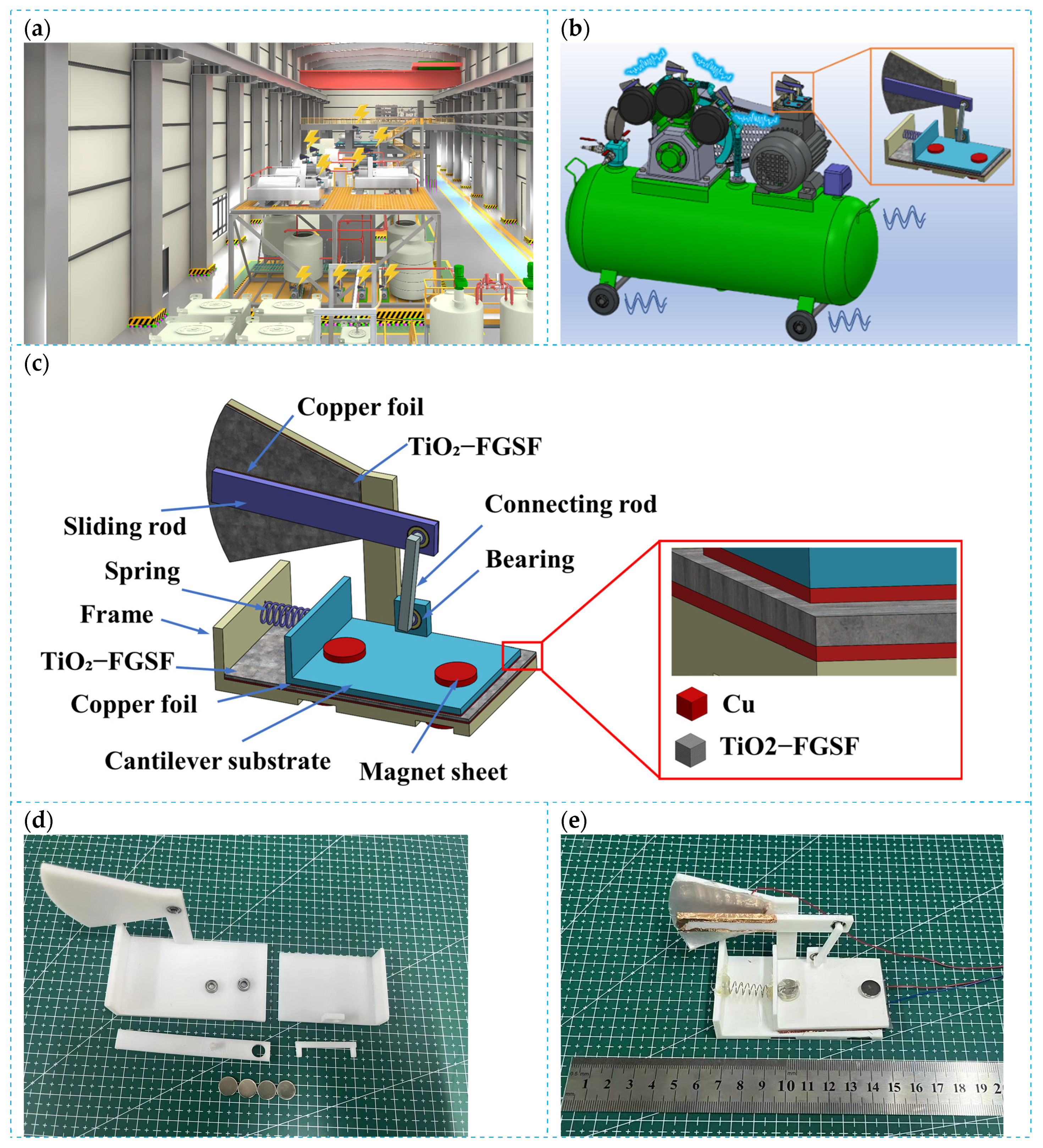
Figure 1 illustrates the application scenarios and manufacturing process of the CR-SC TENG. Figure 1a demonstrates the wide potential of CR-SC TENG in future industrial environments, especially in large factories where multiple CR-SC TENG devices are installed on several air compressors. Each compressor is equipped with a CR-SC TENG which not only effectively harvests mechanical vibration energy but also integrates a real-time monitoring circuit for equipment conditions. This scenario reflects the significant potential for this technology in vibration energy harvesting and equipment health monitoring while offering possibilities for smarter management and maintenance. Figure 1b shows how the CR-SC TENG is practically installed on an air compressor and highlights its industrial applications. The image illustrates the way it connects with the compressor while capturing the slight vibrations during operation and transforming them into electrical energy. This emphasizes CR-SC TENG’s dual function as a highly efficient vibration energy harvester and a self-powered sensing system to monitor equipment and enhance operational efficiency. Figure 1c gives a detailed breakdown of the CR-SC TENG’s structure, with the key components like the frame, movable base, linkage, sliding rod, spring, and bearings labeled. By working together, these components allow the CR-SC TENG to amplify low-frequency, small-amplitude mechanical vibrations, which significantly improves the energy collection efficiency. Figure 1d displays the real-life images of the CR-SC TENG’s parts. These photos help the readers directly observe the key components, such as the frame, base, and sliding rod, and understand their appearance. These images verify the practical feasibility of the design and serve as a reliable reference for performance tests and assembly. Figure 1e shows the fully assembled CR-SC TENG which presents its complete structure and how all the components are combined together.

2.2. Fabrication of Silicone Composite Film Doped with Titanium Dioxide Powder

First, a specific amount of food-grade silicone solvent (FGSS, Dongguan Tianyu Chemical Co., Ltd., TY-866A, Dongguan, China) Part A is mixed with varying amounts of titanium dioxide (TiO2, Guangzhou Nonferrous Metal Industry Group, PTT-GR20, Guangzhou, China) powder and poured into a magnetic stirring container, where it is stirred continuously for 1 h to ensure the complete and even dispersion of the powder. Next, a curing agent (Part B) is added in a 1:5 mass ratio to the original solution, and the mixture is stirred for an additional 10 min. The prepared solution is then poured into a glass container and spread into films of different thicknesses using a four-edge applicator. The films are left to cure at room temperature for 24 h, resulting in food-grade silicone composite films doped with titanium dioxide. The fabrication process is shown in Figure 2a. After the films were fabricated, we used 3000-grit sandpaper to polish the Cu film and the TiO2-FGSS composite film to enhance their frictional properties and surface roughness. This step not only increases the microscopic roughness of the surface but also improves the contact efficiency between the friction materials, which eventually boosts the output performance of the TENG. The SEM images of the polished TiO2-FGSS composite film were obtained using a scanning electron microscope (Zeiss, GeminiSEM 300, Oberkochen, Germany), and are included in Supplementary Material.
To determine the optimal TiO2 doping concentration, composite films measuring 0.5 mm × 4 cm × 4 cm with different TiO2 concentrations are prepared as the negative friction material layer, with copper foil attached to the back as the electrode layer. As shown in Figure 2b, aluminum foil serves as both the positive friction material and electrode layer, forming a contact separation TENG for testing. The test apparatus for triboelectric nanogenerators and the triboelectric layer materials of CR-SC TENG are shown in Supplementary Material. As shown in Figure 2c, a shaker (Wuxi Yutian Technology Co., Ltd., YT-JZ002, Wuxi, China)simulates various vibration scenarios, with the linear motor vibration frequency set to 5 Hz and an amplitude of 1 cm. An oscilloscope (Tektronix, TDS2024B, Beaverton, OR, USA), equipped with an LMC6001 current preamplifier, is used to measure the TENG’s output voltage and short-circuit current. As shown in Figure 2d–g, the electrical output variations in the TENG with different TiO2 doping levels are presented. Both the output voltage and the short-circuit current initially increase and then decrease, reaching their maximum values at a doping ratio of 6%. At this ratio, the output voltage reaches 300 V, and the short-circuit current reaches 12 μA, representing increases of 100% and 80%, respectively, compared to undoped food-grade silicone film. This could be attributed to the doping of TiO2, which increased the dielectric constant of the composite film and enhanced the surface charge density of the friction layer. To verify this, the dielectric constants of both the undoped and 6% doped films were tested, as shown in Figure S4. At a frequency of 100 kHz, the dielectric constant of the TiO2-FGSF composite film with TiO2 doping increased from 3.1 to 4.8, significantly enhancing the triboelectric performance of the film. However, when the doping ratio becomes too high, excessive TiO2 particles precipitate on the surface of the composite film, reducing the effective contact area between the TiO2-FGSF film and the copper electrode, which in turn lowers the electrical output. Therefore, to improve the triboelectric performance of the composite film, the doping ratio needs to be selected within an optimal range. Moreover, TiO2 enhances the charge capture ability of the friction layer, impeding and slowing down the charge dissipation rate. To confirm this, a TENG was prepared using both 6 wt% doped and undoped friction films as a control group, keeping the material size and vibration parameters consistent with the previous experiments. Once the output voltage of both films stabilized, the voltage was measured every 15 min and recorded. Figure S5 shows the variation in the output voltage with time for these two friction films. Due to the intermittent operation of the vibrator, the surface triboelectric charges of both friction films dissipated, and the output voltage showed a pattern of initial decrease followed by stabilization. However, there was a significant difference in the output voltage decay rates between the two films. After 30 min, the output voltage of the undoped film decreased from 158 V to 102 V, while the output voltage of the 6 wt% doped film dropped from 310 V to 261 V. Specifically, the decay rate of the undoped film was 35.4%, while the decay rate of the 6 wt% doped film was only 15.8%. The experimental results indicate that the TiO2 doping in the TiO2-FGSF composite film helps to maintain the triboelectric charge for a longer period of time.
The doping of TiO2 effectively enhances the dielectric constant of the composite film, increasing the surface charge density of the triboelectric layer, thereby improving the output of the TENG. Under the condition of a 6 wt% doping ratio, the TENG was connected in series with resistors of varying resistance values, and the voltage across the resistor and the current passing through it were measured, as shown in Figure 2f. When the resistance increased to 106 Ω, the voltage rose while the current significantly decreased; as the resistance value further increased to 108 Ω, both the voltage and current gradually stabilized. Based on the measured voltage and current data, the output power of the TENG was calculated, as shown in Figure 2g. The load resistance value at the maximum power output represents the optimal matching impedance for the TENG.

2.3. Working Principle of the CR-SC TENG

The CR-SC TENG consists of two triboelectric nanogenerator units, each corresponding to a different triboelectric mode. When subjected to external vibrational excitation, the cantilever beam structure vibrates vertically through the spring and cantilever base, colliding with the overall frame base, forming the first power generation unit in contact separation mode, as shown in Figure 3a. Simultaneously, the sliding rod, connected to the cantilever base by a link, slides along the arc-shaped side of the frame, forming the second power generation unit in a sliding independent layer mode, as shown in Figure 3c.
In the contact separation mode (Figure 3a), the cantilever beam structure achieves contact and separation of the friction layers through periodic vibration. Specifically, when the Cu film and TiO2-FGSF composite film make contact (Figure 3(a-I)), due to the difference in electron affinity between the two materials, the surface of the Cu film becomes positively charged, and the surface of the TiO2-FGSF film becomes negatively charged. Upon receiving external vibrational excitation, the friction layers gradually separate (Figure 3(a-II)), generating a potential difference between them. This drives electrons through the external circuit from the bottom Cu electrode to the top Cu electrode. When the separation of the friction layers reaches its maximum (Figure 3(a-III)), the electrons are completely transferred from the bottom Cu electrode to the top Cu electrode, and the current in the circuit reaches its peak. Subsequently, the friction layers begin to approach again (Figure 3(a-IV)), and the electrons flow in the reverse direction from the top Cu electrode back to the bottom Cu electrode, restoring electrostatic equilibrium and completing one cycle of charge exchange. In the sliding independent layer mode (Figure 3d), the sliding rod drives the TiO2-FGSF composite film to slide along the copper electrode and generate power. In this mode, the TiO2-FGSF composite film has been pre-friction treated and carries charge on its surface, allowing it to generate electricity without direct contact with the electrode. When the TiO2-FGSF film approaches the left side electrode (Figure 3(d-I)), the electric field attracts positive charges to the left electrode. As the film continues to slide to the right (Figure 3(d-II) to Figure 3(d-III)), the positive charges flow through the load from the left electrode to the right electrode, forming a current. When the TiO2-FGSF film completely covers the right side electrode (Figure 3(d-III)), the charge on the right electrode reaches its maximum value. Subsequently, the film slides in the reverse direction (Figure 3(d-IV)), and positive charges flow back through the load to the left electrode, completing the entire charge exchange cycle. In this process, power generation in the sliding independent layer mode does not require direct contact and relies on the distribution of surface charges on the composite film and the potential difference between the two electrodes for energy conversion. Furthermore, through simulation, Figure 3b,e show the electric field distribution and current variation in the contact separation mode and the sliding independent layer mode, respectively, verifying that the working principles of both modes are consistent with the experimental results. The CR-SC TENG achieves efficient conversion of external vibrational energy into electrical energy through the synergistic effect of these two working modes.

2.4. Kinematic Characteristics and Physical Model Analysis of the CR-SC TENG

A key feature of the CR-SC TENG design is the innovative use of a crank-rocker mechanism, which transfers rotational motion while enhancing energy harvesting efficiency through the lever amplification effect. The physical model of the CR-SC TENG is illustrated in Figure 4a. The spring-cantilever section, depicted in Figure 4b, combines the spring and cantilever base to form a spring cantilever beam structure that simulates the reciprocating motion of the crank through its vertical movement. The rocker consists of a lever, with its short end connected to the spring cantilever beam via a connecting rod, while its long end forms sliding contact with the frame. In the initial state, the spring is in its natural position, and both the cantilever beam and rocker are in equilibrium. During operation, the elasticity of the spring enables the spring cantilever beam structure to respond to low-frequency, small-amplitude vibrations, causing it to move up and down, contacting and separating from the frame base. The vibrations of the cantilever beam are transmitted to the short end of the rocker through the connecting rod; the lever then amplifies this motion, causing the long end of the rocker to produce a larger displacement while maintaining sliding contact with the frame. This design effectively combines the lever amplification effect with the crank-rocker mechanism, amplifying small vibrational displacements through the lever system and significantly improving energy harvesting efficiency. The crank-rocker mechanism converts linear and rotational motion and, through the lever structure, amplifies the small vibrations of the cantilever beam, resulting in a substantial displacement at the long end. Consequently, even low-frequency, small-amplitude vibrations can be efficiently captured and converted into electrical energy, meeting the vibration energy harvesting needs of industrial equipment under complex working conditions. This integrated design not only enables precise amplification of low-frequency vibrations but also demonstrates excellent performance in vibration energy conversion and monitoring, making it suitable for a wide range of energy harvesting and intelligent monitoring applications.
The equivalent physical model of the CR-SC TENG is shown in Figure 4c, which combines a crank-rocker mechanism with a lever mechanism. The first power generation section of the CR-SC TENG device forms a cantilever beam structure, with the cantilever base connected by a spring that undergoes contact and separation with the frame base during vertical vibrations. Based on structural mechanics, a dynamic model of the cantilever beam’s vibration can be established to analyze its motion characteristics. Here, the deformation primarily occurs in the spring, with the transverse displacement of the spring denoted by (x, t), where x represents the position along the length of the spring, and t represents time. For a small segment dx, the vibration equation of the spring can be expressed as follows:
m 2 y ( x , t ) t 2 = k 2 y ( x , t ) x 2
This is the wave equation for the spring cantilever beam, where m is the mass per unit length, and k is the spring stiffness.
Assuming that the spring’s vibration takes the form of simple harmonic motion, the following equation can be derived:
y ( x , t ) = Y ( x ) cos ( ω t )
After simplification, we obtain the following:
d 2 Y ( x ) d x 2 m ω 2 k Y ( x ) = 0
Define λ 2 = m ω 2 k , resulting in the following differential equation:
d 2 Y ( x ) d x 2 λ 2 Y ( x ) = 0
The general solution to this differential equation is as follows:
Y ( x ) = A cosh ( λ x ) + B sinh ( λ x )
Considering the boundary conditions of the cantilever beam:
At the fixed end x = 0:
Y ( 0 ) = 0 A = 0
At the free end x = L:
k Y ( L ) = E I d 3 Y ( L ) d x 3
Since A = 0, the general solution simplifies to the following:
Y ( x ) = B sinh ( λ x )
Substitute the boundary condition at the free end, and calculate: d 3 Y ( x ) d x 3 :
d Y ( x ) d x = B λ cosh ( λ x ) d 2 Y ( x ) d x 2 = B λ 2 sinh ( λ x ) d 3 Y ( x ) d x 3 = B λ 3 cosh ( λ x )
At x = L , apply the boundary condition:
k B sinh ( λ L ) = E I B λ 3 cosh ( λ L )
By simplifying the above equation, we obtain the following:
tanh ( λ L ) = E I λ 3 k
Using numerical analysis with Newton’s method, we can determine the eigenvalue λ n , this eigenvalue can then be used to calculate the natural frequency:
ω n = λ n k m
The spring stiffness k is a crucial parameter that describes the spring’s resistance to deformation. It is primarily influenced by the material’s elastic modulus E, the effective number of coils N, the wire diameter d, the mean diameter D, and the geometry of the spring. For a helical compression spring, the stiffness k can be calculated using the following formula:
k = G d 4 8 N D 3
Based on this formula, to increase the output of the first power generation unit of the CR-SC TENG under a specific vibration amplitude (external excitation), it is essential to select an appropriate natural frequency ω n and to moderately enhance the spring stiffness. This can be achieved by choosing spring models with suitable parameter values.
The second triboelectric generation unit of the CR-SC TENG employs the crank-rocker and lever principles to convert the vertical motion of the spring’s cantilever base into relative sliding motion between various endpoints. Figure 4d presents the physical model diagram of the crank-rocker mechanism.To establish the kinematic equation for the crank-rocker mechanism, let represent the length of section AB of rod ABE, L 5 the length of section AE, L 2 the length of rod BC, L 3 the length of section CD, and L 4 the distance AD. Here, AD is fixed, while rods ABE and CD are free to rotate. At any given time point t, the position of point B can be expressed as follows:
x B = L 1 cos ( ω t )
y B = L 1 sin ( ω t )
Here, ω denotes the angular velocity. To determine the position of point C, we use the loop closure equation, with point D fixed at coordinates ( x D , y D ) ; based on L4 and the initial angle, these coordinates can be calculated. The position of point C ( x C , y C ) can be derived from the following loop equation:
( x C x D ) 2 + ( y C y D ) 2 = L 3 2
( x C x B ) 2 + ( y C y B ) 2 = L 2 2
Solving this equation requires numerical methods, which can be implemented using MATLAB’s optimization functions (MATLAB R2024a, MathWorks, Natick, MA, USA). Detailed steps are provided in the Supplementary Material, with specific code shown in Supplementary Figure S6. Since rod ABE functions as a lever, the position of point C can be expressed in terms of the position of point E.
The lever amplification effect significantly enhances the energy collection efficiency of the CR-SC TENG [34]. By amplifying a small input displacement, the system effectively increases the sliding distance at the output, thereby enlarging the friction surface contact area, which improves charge collection efficiency and output power. As illustrated in Figure 4e, the lever amplification model includes endpoints B and E, with the fulcrum at point A; the length of segment AB is L 1 , and that of AE is L 5 . When the lever rotates around the fulcrum by θ, the arc lengths formed by points B and E are calculated as follows:
L B = L 1 θ
L E = L 2 θ
These two arcs, together with the fulcrum, form sectors, with the area of each sector represented as follows:
S B = 1 2 L 1 2 θ
S E = 1 2 L 2 2 θ
Since the AE end is longer than the AB end, when the AB end undergoes a given displacement, the AB end will experience a proportionally larger displacement. Specifically, the displacement of the AE end is L 2 / L 1 times that of the Ab end, and the rotational area of the AE end is the square of the rotational area of the AB end:
S E = L 2 L 1 2 S B
As a result, with the rotational sliding motion, the sliding distance and relative displacement of the AE end relative to the frame are significantly greater than those of the AB end. This amplification effect substantially enhances the energy conversion efficiency of the triboelectric nanogenerator.

2.5. Influence and Optimization of Structural Parameters of CR-SC TENG

To achieve higher output from the triboelectric nanogenerator, ensuring thorough contact between the two friction layers is crucial [35]. Several parameters of the CR-SC TENG significantly affect this contact. Therefore, optimizing these parameters is necessary to maximize contact between the two friction layers and enhance the output capacity of the TENG. As shown in 
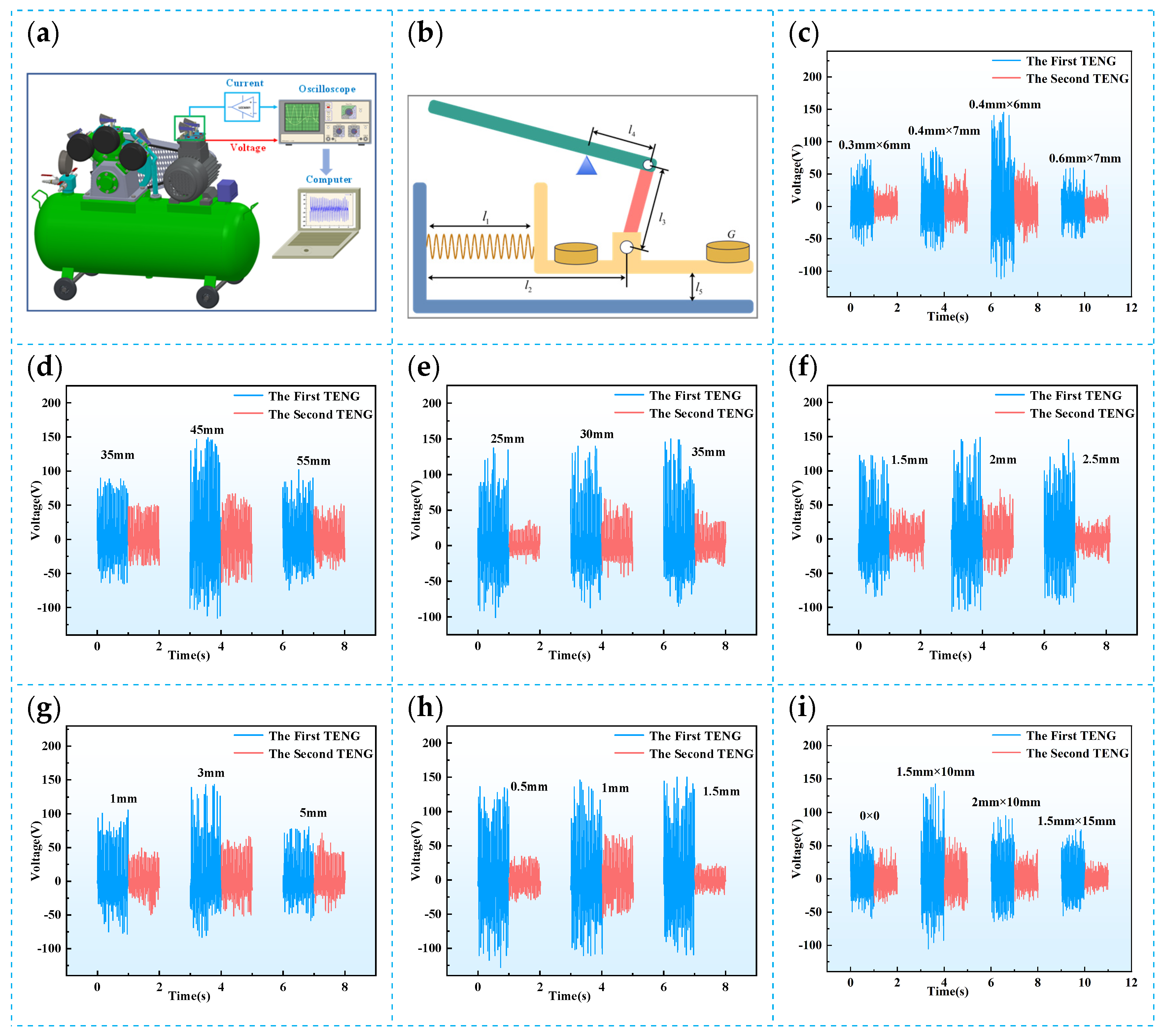
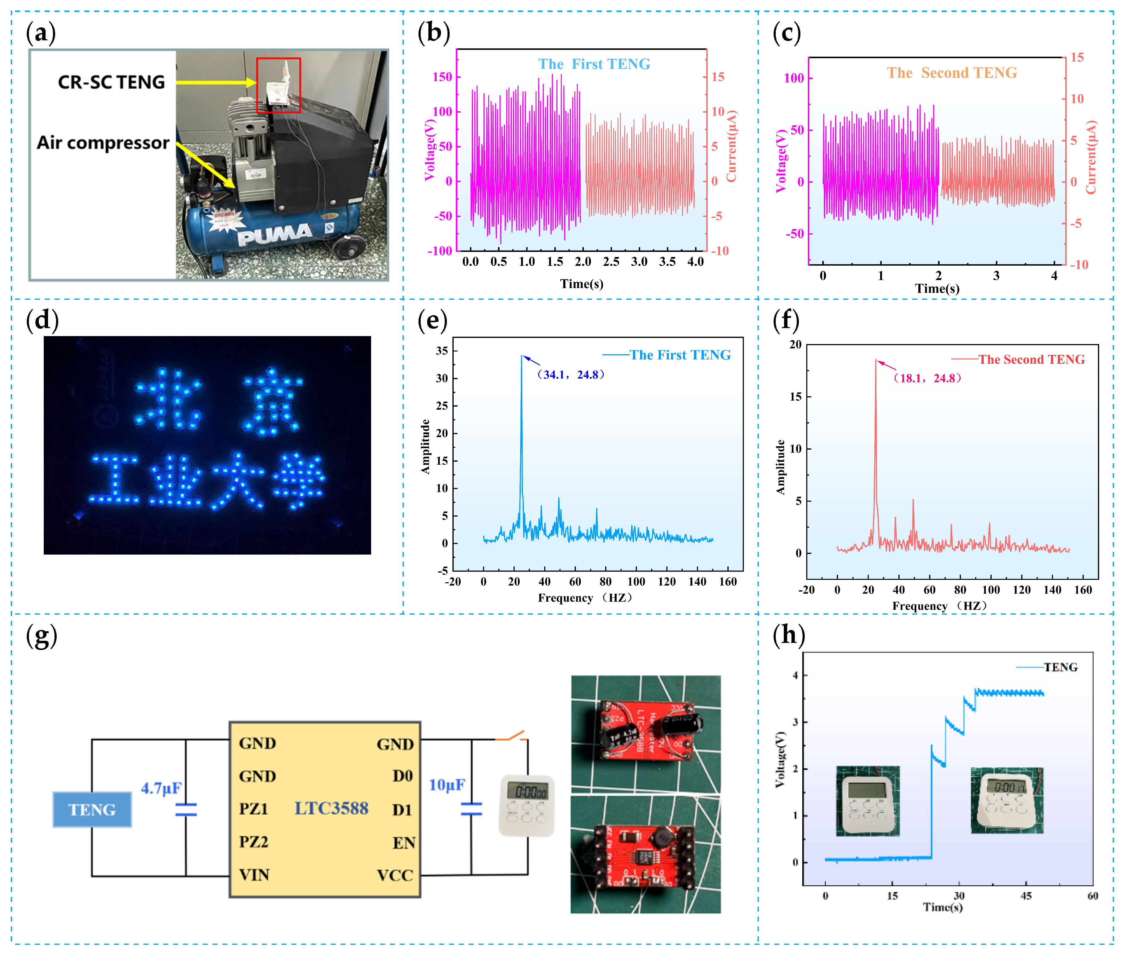
Figure 5a, an air compressor serves as the test platform for structural parameter optimization, enabling the analysis of the CR-SC TENG’s output performance. As demonstrated in Supplementary Video S1, when the CR-SC TENG is installed on an air compressor, both the first and second friction units exhibit a clear contact separation process. Figure 5b shows a simplified schematic of the CR-SC TENG structure, where l 1 represents the spring length, l 2 the crank length, l 3 the connecting rod length, l 4 the rocker (driving arm) length, l 5 the resistance arm length, l 6 the distance from the cantilever base to the upper surface of the frame base (the distance between the first friction layers), and G the mass of the magnetic sheet. In the CR-SC TENG, the key parameters for optimization include the lengths of the crank, connecting rod, and rocker in the crank-rocker structure, the ratio of the driving arm to the resistance arm in the lever structure, spring parameters, and the properties of the attached magnetic sheet. In the following experiments, each parameter will be optimized individually as the sole variable, with all other parameters maintained at their fixed optimal values.
The spring is a critical component in the CR-SC TENG structure, providing support and transmitting vibrations. The diameter, length, and stiffness of the spring directly influence the performance of the TENG. Figure 5c illustrates the impact of spring parameters on the open-circuit voltage of the CR-SC TENG. When the spring stiffness is too low—such as a spring with a diameter of 0.3 mm and a length of 6 mm—the spring cannot effectively support the movement of the cantilever base, resulting in insufficient impact force, reduced contact between the friction layers, and lower charge transfer efficiency, leading to a low output voltage. Conversely, when the spring stiffness is too high—such as with a 0.6 mm × 7 mm spring—the spring is unable to generate sufficient vibration amplitude under weak excitation, leading to poor energy collection efficiency. This is because excessive stiffness restricts the elastic deformation of the cantilever beam, limiting its ability to transmit vibrational energy from the excitation source effectively. Therefore, choosing the right spring stiffness is vital. However, adjusting the spring stiffness not only affects the output voltage but also influences other performance characteristics of the device, such as stability and longevity. For example, springs with lower stiffness might cause fatigue damage after running for a longer period; thus, they shorten the lifespan of the device. On the other hand, their greater elasticity might negatively affect the stability of the device while springs with higher stiffness could increase the output voltage in the short term. Over extended use, the spring may experience excessive wear, which could potentially reduce the device’s performance and lifespan. Therefore, selecting a spring with a diameter of 0.4 mm and a length of 6 mm not only enhances the vibration amplitude but also helps to balance the device’s long-term lifespan. The final experimental results show that with this spring configuration, the first friction unit has an open-circuit voltage (Voc) of 150 V, and the second friction unit has a Voc of 60 V. This shows that the spring optimization improves the output voltage while ensuring the device’s stability and longevity.
The crank-rocker mechanism, known for its simplicity, reliability, and efficient motion conversion, is widely used in applications requiring conversion between linear and rotational motion. In the CR-SC TENG, the crank-rocker mechanism consists of a crank, connecting rod, and rocker (driving arm) and transmits the vertical vibration of the spring’s cantilever beam to the lever structure, driving the sliding rod and activating energy conversion in the second friction unit. As a critical component in motion conversion, the crank length directly affects the efficiency of vibration transmission. Figure 5d shows the output voltage of the CR-SC TENG at different crank lengths. Experimental results indicate that as the crank length increases from 35 mm to 45 mm, the output voltage also increases. This is because a longer crank provides greater driving torque, enhancing the vibration of the cantilever base and the sliding rod. However, when the crank length is further increased to 55 mm, the output voltage drops significantly. Although a longer crank increases torque, excessive length weakens the spring’s support function, potentially causing the cantilever base’s end to contact the frame base, reducing the effective contact area and contact efficiency between the friction layers, resulting in decreased output voltage. Therefore, the optimal crank length in the design should be between 45 mm and 55 mm. Experimental validation shows that a crank length of 45 mm provides a good balance of torque output and stable support, preventing contact between the end and the frame base and achieving optimal voltage output.
The connecting rod is a critical component linking the spring’s cantilever base with the sliding rod, and its length directly affects motion transfer efficiency and the contact quality of the friction units. Figure 5e shows the open-circuit voltage of the CR-SC TENG for various connecting rod lengths. If the connecting rod is too short, the sliding rod moves too quickly, which may lead to insufficient contact between the friction units, reducing charge transfer and resulting in lower output voltage. Conversely, if the connecting rod is too long, the sliding rod moves more slowly, reducing contact time and limiting effective interaction between the friction units, which also lowers the output voltage. Experimental optimization determined that a connecting rod length of 30 mm yields the highest output voltage. This length ensures that the sliding rod achieves sufficient movement amplitude while also providing optimal motion transfer efficiency, facilitating effective contact between the friction layers and significantly enhancing voltage output. The rocker, which serves as the driving arm in the lever structure, has considerable mechanical advantages, and its length critically impacts the output voltage of the second friction unit. Figure 5f displays the open-circuit voltage of the CR-SC TENG at different rocker lengths. Experimental results show that when the driving arm is too short, the rocker cannot effectively drive the resistance arm’s vertical motion, which reduces the vibration amplitude of the cantilever beam and affects output voltage. Conversely, if the driving arm is too long, although it can more effectively drive the resistance arm, it may overly restrict the vibration of the cantilever beam, also reducing output voltage. Thus, selecting an appropriate length for the driving arm is essential. Through optimization experiments, a driving arm length of 2 mm was found to be ideal, as it supports the resistance arm’s movement while maintaining effective vibration of the cantilever beam, thereby improving voltage output.
The initial distance between the cantilever base and the frame base, i.e., the distance between the friction layers of the first friction unit—directly determines the contact efficiency and effectiveness of charge transfer between the friction layers. Figure 5g shows that when this distance is 1 mm, the cantilever base’s movement range is limited, producing a small impact force and incomplete contact between the friction units, which reduces charge transfer efficiency and results in low output voltage. When the distance between the friction layers of the first friction unit is increased to 5 mm, the cantilever base’s movement range expands, but the contact area decreases, reducing charge transfer efficiency and lowering output voltage. Therefore, optimizing the initial distance between the cantilever base and the frame base is essential to enhance the voltage output of the CR-SC TENG. Experimental results indicate that a distance of 3 mm between the friction layers of the first friction unit produces the highest output voltage. At this distance, the friction units maintain sufficient contact while supporting a larger impact force, achieving optimal voltage output.
Figure 5h illustrates the effect of the distance between the sliding rod and the frame side—specifically, the distance between the friction layers of the second friction unit—on the output voltage of the CR-SC TENG. When this distance is 0 mm, the sliding friction layers are in overly tight contact, causing significant resistance to the sliding rod’s motion and restricting the vertical vibration of the spring’s cantilever beam, resulting in a lower output voltage. Conversely, when the distance between the friction layers of the second unit is increased to 2 mm, contact efficiency between the layers decreases, leading to a substantial drop in charge transfer efficiency and, consequently, a lower output voltage. Thus, optimizing the distance between the sliding rod and the frame side to maintain a suitable non-contact, independent sliding layer mode between the friction layers is crucial for improving energy conversion efficiency and output voltage. Experimental results indicate that a distance of 1 mm between the friction layers of the second unit yields the highest output voltage. At this distance, the second friction layers maintain an appropriate non-contact state while allowing the free vibration of the spring cantilever beam, achieving optimal voltage output.
Incorporating magnets can effectively enhance the TENG’s output performance. To further improve the output of the CR-SC TENG, magnetic sheets were added to the system, using magnetic attraction and repulsion to optimize the contact state between the friction units, thereby enhancing charge transfer efficiency. A suitable amount of magnetic material can adjust the distance between the friction layers, preventing energy loss due to overly tight contact or efficiency reductions from excessive separation. Properly selected magnetic sheet mass also increases the stability of the cantilever base, allowing smoother motion of the cantilever beam and improving overall energy conversion efficiency. Figure 5i shows the voltage output of the CR-SC TENG with varying magnetic sheet masses. Figure S7 shows the specific output voltage of the CR-SC TENG without a magnet. Experimental results indicate that adding magnetic sheets significantly increases the output voltage. As the magnetic sheet mass increases, the output voltage initially rises and then decreases. A suitable mass of magnetic sheets enhances the inertia of the spring’s cantilever beam, improving contact between the friction layers through magnetic forces, which boosts charge transfer efficiency. However, if the magnetic sheet mass is too high, excessive inertia limits the movement freedom of the cantilever beam, reducing the system’s response speed and ultimately causing a decrease in output voltage. To further improve contact between the spring’s cantilever beam and the frame base, as well as to balance the movement of the cantilever base, magnetic sheets were placed at both the initial and terminal ends of the cantilever base. Magnetic sheets with opposite poles were placed at the initial end to increase contact force, while sheets with like poles were positioned at the terminal end to stabilize the cantilever base’s movement through magnetic attraction and repulsion. This design effectively balances the motion of the cantilever beam, stabilizes contact between the friction layers, and enhances overall voltage output performance.
Through the comprehensive optimization of the structural parameters of the CR-SC TENG, the interactions among various parameters have been effectively balanced. The optimized CR-SC TENG demonstrates outstanding output performance and stability in practical applications, such as in air compressors. Figure S8 illustrates the durability of the CR-SC TENG. After continuous operation for one hour, the output of the CR-SC TENG still remains at a relatively high level. Optimizing each structural parameter not only enhances the TENG’s electrical output capacity but also improves the system’s structural stability, allowing the CR-SC TENG to maintain reliable output over a prolonged operation. This provides a robust technical foundation for the CR-SC TENG’s practical application in industrial equipment vibration energy harvesting, self-powered sensing, and other low-power electronic devices.

2.6. Output Performance Under Different External Excitation Conditions

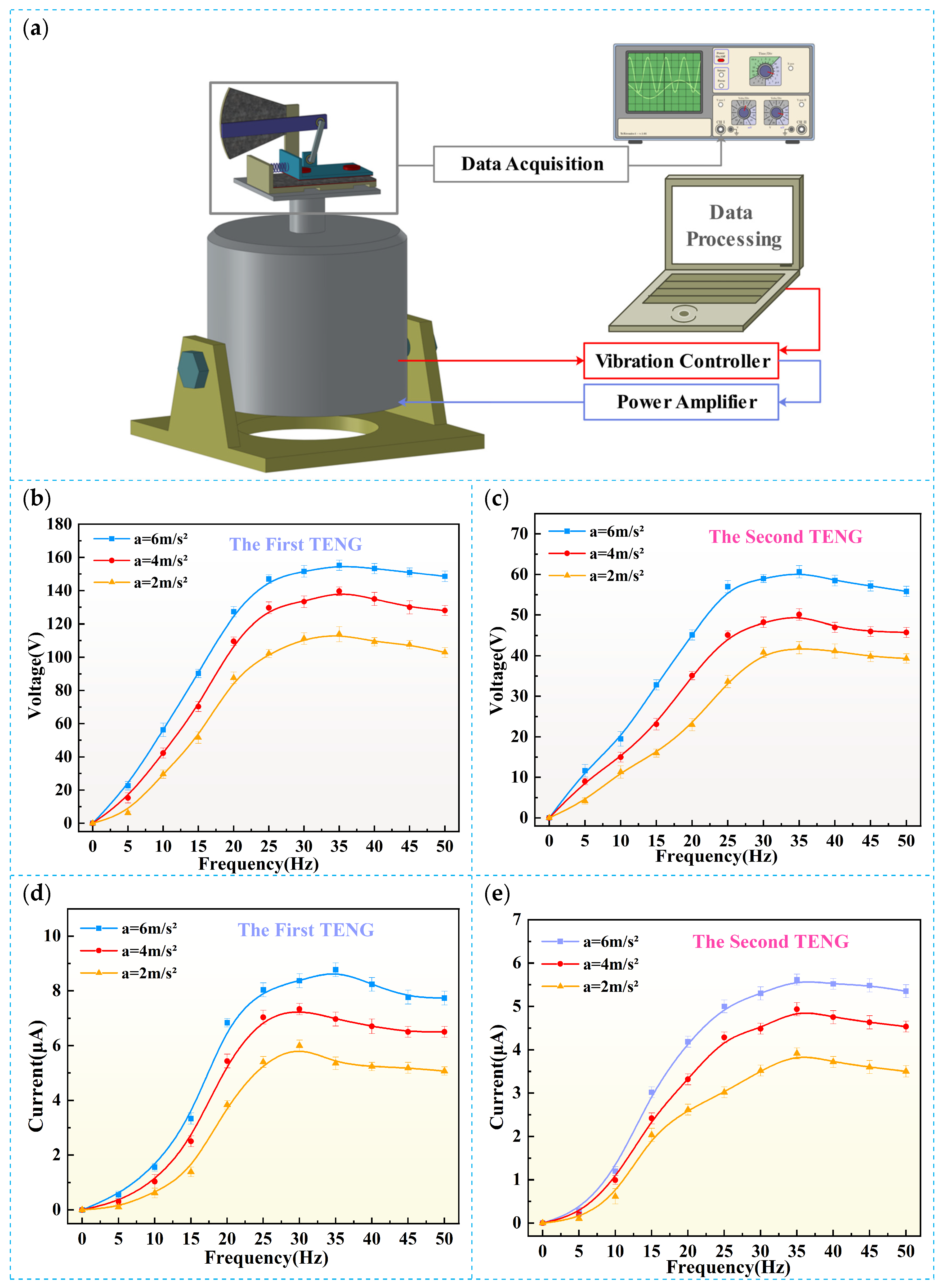
An experimental platform was used to simulate an industrial vibration environment in order to evaluate the output performance of the CR-SC TENG under various external excitation conditions. As shown in Figure 6a, this platform generates vibrations using an exciter and adjusts the frequency and acceleration of the vibration to test the CR-SC TENG’s response under different excitation conditions. The platform can accurately simulate the vibrations produced by industrial equipment like air compressors and engines during operation, providing a good condition to assess its output performance under various vibration scenarios. Figure 6b,c show the variation in the open-circuit voltage and short-circuit current of the first output unit of the CR-SC TENG with frequency at different acceleration levels. The experiments covered a frequency range of 0–50 Hz which is common for vibration frequencies of industrial equipment. As the frequency increased, both the open-circuit voltage and the short-circuit current of the first output unit increased significantly, peaking at 35 Hz. Particularly, an acceleration of 6 m/s2 with the open-circuit voltage reached 155 V, and the short-circuit current was 8.7 μA, showing excellent energy conversion performance. Similarly, Figure 6d,e display the variation in the open-circuit voltage and the short-circuit current of the second output unit under different accelerations. Like the first output unit, the second unit also reached its peak output at 35 Hz. As the acceleration increased, both the voltage and current improved gradually. At an acceleration of 6 m/s2, the second output unit showed an open-circuit voltage of 61 V and a short-circuit current of 5.4 μA. Although the performance of the second output unit was slightly lower than that of the first, it still demonstrated good energy conversion efficiency in the low- and mid-frequency ranges.
As the vibration frequency increased, the output performance of the first output unit of the CR-SC TENG reached its peak at 35 Hz. After this point, both the open-circuit voltage and the short-circuit current started to decrease, which is mainly due to the delayed response of the mechanical components to high-frequency vibrations or the limitations in the performance of the friction materials. This means that the CR-SC TENG is highly suitable for industrial vibration equipment, particularly in low- to mid-frequency vibration environments. Although its performance slightly declines in high-frequency conditions, the CR-SC TENG still maintains a relatively high output of voltage and current, showing good stability and energy collection capacity. Overall, the experimental results indicate that the output performance of the CR-SC TENG under various external excitation conditions is largely dependent on key factors like frequency and acceleration. Both the output voltage and current increase significantly with an increase in acceleration. It strongly supports its potential for energy harvesting and equipment monitoring in practical industrial applications.

3. CR-SC TENG Application Demonstration

3.1. CR-SC TENG for Vibration Energy Harvesting

The CR-SC TENG offers extensive application potential, particularly in industrial vibration equipment such as air compressors, engines, and various machines that generate mechanical vibrations, enabling self-powered vibration monitoring and energy harvesting [36,37]. To evaluate the practical application capability of the CR-SC TENG in industrial vibration equipment, the device was installed on a commonly used industrial air compressor as a test environment. As shown in Figure 7a, the CR-SC TENG operates effectively on the air compressor. The output performance of the first triboelectric nanogenerator unit (TENG Unit 1) and the second triboelectric nanogenerator unit (TENG Unit 2) was measured separately. As shown in Figure 7b, TENG Unit 1 achieved an open-circuit voltage of 150 V and a short-circuit current of 8 μA, while Figure 7c shows that TENG Unit 2 achieved an open-circuit voltage of 60 V and a short-circuit current of 5 μA. These results demonstrate that the CR-SC TENG can effectively harvest energy from mechanical vibrations. Furthermore, the electrical energy generated by the CR-SC TENG can power small electrical devices. As illustrated in Figure 7d, when powered solely by the CR-SC TENG, the pattern of Chinese characters “北京工业大学“ (Beijing University of Technology), which was formed by 118 serially connected LED light patches, was successfully lit up. This showcases its potential for powering low-power electronic devices. To further verify the CR-SC TENG’s sensitivity to vibration signal frequency, a Fast Fourier Transform (FFT) analysis was conducted. As shown in Figure 7e,f, the FFT results of the open-circuit voltage signals from TENG Units 1 and 2 indicate a maximum amplitude of 24.8 Hz. This confirms that the CR-SC TENG accurately reflects the main vibration frequency of the air compressor, demonstrating its high sensitivity and accuracy in vibration monitoring applications.
Due to the high-voltage, low-current, and high-impedance output characteristics of the TENG, it cannot directly meet the stable power requirements of conventional electronic devices [38,39]. To address this issue, a power management circuit based on the LTC3588 chip was designed as shown in Figure 7g. The left side of Figure 7g shows the schematic diagram of the LTC3588 power management circuit while the right side presents the physical image of the circuit with soldered capacitors. This circuit connects the rectified TENG output to energy storage components and converts it into a stable output voltage through the power management system. In order to protect the LTC3588 chip from the high voltage output of the TENG, a 4.7 μF capacitor is connected in parallel at the input of the circuit. This capacitor’s role is to buffer and limit the voltage fluctuations from the TENG output, preventing excessive voltage from damaging the chip. More specifically, the 4.7 μF capacitor can store charge from the TENG and then releases when the voltage is lower, smoothing the input voltage fluctuations and ensuring it remains within the safe operating range of the LTC3588. Additionally, a 10 μF capacitor is connected in parallel at the output of the LTC3588 to further store and stabilize the output voltage. This capacitor effectively stabilizes the output voltage and ensures a reliable power supply to the load. The 4.7 μF and 10 μF capacitors work together to manage the high-voltage output from the TENG to ensure that the LTC3588 chip operates within a stable voltage range by this design. This ensures a continuous and reliable power supply for low-power electronic devices.
Using this power management module, the CR-SC TENG can effectively charge a capacitor after operating on an air compressor for a period, providing continuous power to a small stopwatch. As shown in Figure 7h, the output voltage of the LTC3588 chip rises steadily to 2.5 V after 22 s of CR-SC TENG operation, then gradually drops to 2 V, rises again to 3.2 V, and then drops to 2.8 V. After three such fluctuations, the voltage stabilizes at 3.6 V at 33 s. This indicates that, despite some initial fluctuations in capacitor charging and discharging, the power management circuit effectively stabilizes the TENG’s output voltage at a higher level, providing continuous and stable power for the small stopwatch.
The experimental results demonstrate that the CR-SC TENG not only efficiently harvests mechanical vibration energy but also, through the power management circuit, provides stable power for various low-power devices, highlighting its broad potential in self-powered vibration monitoring systems. This intelligent sensor design offers an innovative solution for industrial equipment condition monitoring, contributing to improved operational efficiency and safety.

3.2. CR-SC TENG as a Self-Powered Sensor

In industrial environments, monitoring the operational status of equipment is essential [40]. The CR-SC TENG not only performs excellently in vibration energy harvesting but also functions as a self-powered vibration sensor, enabling the continuous monitoring of mechanical equipment and motor vibrations without an external power supply [41]. This makes it highly promising for applications in industrial equipment monitoring. As shown in the application example in Figure 8a, the CR-SC TENG effectively captures vibration energy from industrial equipment and transmits real-time voltage signals to a host computer through a wireless monitoring module.
The wireless monitoring module operates by capturing and processing analog voltage signals. As shown in Figure 8b, the module first uses the ADC pin of an STC8G1K08A-36I-SOP8 microcontroller to collect signals from the triboelectric nanogenerator output. To protect the microcontroller from high voltage, a bidirectional DVS diode is added to the generator output. The internal voltage divider network of the module consists of pull-up resistors (a fixed 100 K and an adjustable 1 M) and pull-down resistors (with the same configuration) to form a voltage divider. The AC current generated by the triboelectric nanogenerator passes through the pull-down resistor, creating corresponding voltage changes across the resistor according to Ohm’s law. These voltage variations reflect the operating status of the generator. The ADC pin of the microcontroller can then monitor these voltage changes in real time, indicating the working status of the CR-SC TENG and, consequently, the condition of the equipment. The monitoring module transmits the captured voltage signal to a Bluetooth app every 10 milliseconds, as shown in Figure 8c, with the option to adjust to real-time transmission at a frequency of less than 1 millisecond if needed. Figure 8d,e show the open-circuit voltage monitored at different frequencies using an oscilloscope and the wireless monitoring module, respectively, while Figure 8f compares the open-circuit voltage data from both. The monitoring results indicate that the error between the open-circuit voltage measured by the oscilloscope and the wireless monitoring module is less than 3%, demonstrating the wireless monitoring system’s high accuracy and stability.
As a self-powered sensor, the CR-SC TENG combines efficient energy conversion capability with advanced wireless transmission technology, enabling it to operate effectively in low-frequency, low-amplitude vibration environments. This feature gives it significant application potential, particularly for vibration energy recovery in industrial equipment and for self-powered environmental monitoring systems.

4. Conclusions

This paper presents and develops a triboelectric nanogenerator (CR-SC TENG) based on the principles of a crank-rocker and spring cantilever structure. The CR-SC TENG is designed to efficiently harvest low-amplitude vibration energy generated by industrial equipment under real-world conditions and to function as a self-powered sensor for real-time monitoring. By integrating a crank-rocker mechanism with a spring cantilever beam, the device optimizes the reciprocating motion of the friction layers, significantly enhancing energy harvesting efficiency. In the design of the friction layers, the vertical contact and sliding contact parts are constructed using surface-treated copper foil and food-grade silicone film doped with titanium dioxide powder, respectively. This configuration improves charge transfer efficiency while also enhancing the device’s stability and durability. The paper provides a detailed analysis of the CR-SC TENG’s operating principles, establishes a physical model, and derives the relevant mathematical expressions. Using COMSOL finite element software (COMSOL Multiphysics 5.6, COMSOL Inc., Burlington, MA, USA), simulations of the displacement and electric field distribution of the friction layers were conducted, examining the impact of various design parameters on peak voltage to inform optimization. Experimental results indicate that within a vibration frequency range of 1–35 Hz and a vibration amplitude range of 1–3 mm, the CR-SC TENG effectively amplifies low-amplitude vibrations and significantly improves energy conversion efficiency.
To achieve stable power output, a power management circuit based on the LTC3588 chip was designed and tested on industrial equipment such as air compressors. Experimental data showed that the first TENG unit achieved an open-circuit voltage of 150 V and a short-circuit current of 8 μA, while the second TENG unit achieved an open-circuit voltage of 60 V and a short-circuit current of 5 μA. Fast Fourier Transform (FFT) analysis revealed that the main vibration frequency of the air compressor was 24.8 Hz, indicating that the CR-SC TENG can accurately capture the vibration characteristics of the equipment, demonstrating high sensitivity and accuracy. The CR-SC TENG also shows great potential as a self-powered vibration sensor for industrial equipment monitoring. Equipped with a wireless monitoring module, the CR-SC TENG can monitor vibration signals in real time without an external power source and wirelessly transmit data to a host computer for analysis. For example, in a real factory environment, the CR-SC TENG can operate on an air compressor running at a vibration frequency of 25 Hz, reliably outputting voltage to power a temperature and humidity sensor and providing continuous power for low-power devices such as LED lights and small timers. In this way, the CR-SC TENG not only serves as an energy harvester but also functions as an independent self-powered sensor, playing an important role in industrial automation and environmental monitoring.
In conclusion, the CR-SC TENG combines efficient energy conversion with self-powered sensing capability, demonstrating broad application potential in low-frequency, low-amplitude vibration environments. It is particularly promising for applications in industrial equipment health monitoring, energy recovery, and self-powered sensor systems.

Supplementary Materials

The following supporting information can be downloaded at: https://www.mdpi.com/article/10.3390/electronics13245032/s1, Figure S1. Schematic diagram of main structural parameters of the CR-SC TENG. Figure S2. Scanning electron microscopy (SEM) images of TiO2-FGSF. Figure S3. Test Apparatus and Material Preparation for the Triboelectric Layer of CR-SC TENG. Figure S4. The dielectric constants of the undoped film and 6 wt% doped film. Figure S5. The variation of output voltage with time for TENG under doping and 7 wt% doping. Figure S6. Physical Model of CR-SC TENG and MATLAB Solution Code. Figure S7. The Voc of the CR-SC TENG without any magnet. Figure S8. The durability of CR-SC TENG.

Author Contributions

Methodology, X.W.; Formal Analysis, G.Y.; Data Curation, G.Y.; Writing—Original Draft, X.X.; Writing—Review and Editing, X.W.; Visualization, G.Y.; Project Administration, T.S.; Funding Acquisition, T.S. All authors have read and agreed to the published version of the manuscript.

Funding

This research received no external funding.

Data Availability Statement

The original contributions presented in this study are included in the article and Supplementary Material. Further inquiries can be directed to the corresponding author.

Conflicts of Interest

The authors declare no conflicts of interest.

References

  1. Midilli, A.; Dincer, I.; Rosen, M.A. The Role and Future Benefits of Green Energy. Int. J. Green. Energy 2007, 4, 65–87. [Google Scholar] [CrossRef]
  2. Xu, M.; Wang, P.; Wang, Y.C.; Zhang, S.L.; Wang, A.C.; Zhang, C.; Wang, Z.; Pan, X.; Wang, Z.L. A Soft and Robust Spring Based Triboelectric Nanogenerator for Harvesting Arbitrary Directional Vibration Energy and Self-Powered Vibration Sensing. Adv. Energy Mater. 2018, 8, 1702432. [Google Scholar] [CrossRef]
  3. Tian, X.L.; Hu, S.G.; Qin, H.B.; Zhao, J.; Ran, L.Y. Energy Consumption and Energy Saving Research Status of Air Compressor System. Mater. Sci. Mech. Eng. Appl. Res. 2014, 628, 225–228. [Google Scholar] [CrossRef]
  4. Jiang, H.; Yu, S.Z.; Liu, J.L.; Zhang, B.P. Design of automatic refueling system for air compressor. In Design, Manufacturing and Mechatronics, Proceedings of the 2015 International Conference on Design, Manufacturing and Mechatronics (ICDMM2015), Wuhan, China, 17–18 April 2015; World Scientific: Singapore, 2016; pp. 241–250. [Google Scholar]
  5. Zhang, Z.H.; Gu, G.Q.; Zhang, W.H.; Du, Z.L.; Cheng, G. Triboelectric nanogenerator with enhanced charge density and limited open-circuit voltage for efficient power management and industrial environmental monitoring. Nano Energy 2024, 131, 110308. [Google Scholar] [CrossRef]
  6. Caetano, T.; Winkler, H.; Depledge, J. Towards zero carbon and zero poverty: Integrating national climate change mitigation and sustainable development goals. Clim. Policy 2020, 20, 773–778. [Google Scholar] [CrossRef]
  7. Raza, S.; Ghasali, E.; Raza, M.; Chen, C.; Li, B.; Orooji, Y.; Lin, H.; Karaman, C.; Karimi Maleh, H.; Erk, N. Advances in technology and utilization of natural resources for achieving carbon neutrality and a sustainable solution to neutral environment. Environ. Res. 2023, 220, 115135. [Google Scholar] [CrossRef]
  8. Hadas, Z.; Vetiska, V.; Singule, V.; Andrs, O.; Kovar, J.; Vetiska, J. Energy Harvesting from Mechanical Shocks Using a Sensitive Vibration Energy Harvester. Int. J. Adv. Robot. Syst. 2012, 9, 225. [Google Scholar] [CrossRef]
  9. Wang, X.H.; Yin, G.F.; Sun, T.; Xu, X.J.; Rasool, G.; Abbas, K. Mechanical Vibration Energy Harvesting and Vibration Monitoring Based on Triboelectric Nanogenerators. Energy Technol. 2024, 12, 25. [Google Scholar] [CrossRef]
  10. Moreno-Merino, L.; Jiménez-Hernández, M.E.; de la Losa, A.; Huerta-Muñoz, V. Comparative assessment of button cells using a normalized index for potential pollution by heavy metals. Sci. Total Environ. 2015, 526, 187–195. [Google Scholar] [CrossRef]
  11. Zhao, S.; Zhang, W.; Li, G.; Zhu, H.; Huang, J.; He, W. Ultrasonic renovation mechanism of spent LCO batteries: A mild condition for cathode materials recycling. Resour. Conserv. Recycl. 2020, 162, 105019. [Google Scholar] [CrossRef]
  12. Yang, J.; Yang, Y.; Li, A.; Wang, Z.; Wang, H.; Yu, D.; Hu, P.; Qian, M.; Lin, J.; Guo, L. Sustainable treatment of dye wastewater for high-performance rechargeable battery cathodes. Energy Storage Mater. 2019, 17, 334–340. [Google Scholar] [CrossRef]
  13. Wang, X.; Zhang, Y.; Xue, S.; Wang, T.; Fu, G.; Mao, X.; Lu, C. Bi-stable electromagnetic generator with asymmetrical potential wells for low frequency vibration energy harvesting. Mech. Syst. Signal Pract. 2023, 199, 110478. [Google Scholar] [CrossRef]
  14. Yang, T.; Cao, Q.; Hao, Z. A novel nonlinear mechanical oscillator and its application in vibration isolation and energy harvesting. Mech. Syst. Signal Pract. 2021, 155, 107636. [Google Scholar] [CrossRef]
  15. Liu, Q.; Qin, W.; Yang, Y.; Zhou, Z. Harvesting weak vibration energy by amplified inertial force and multi-stable buckling piezoelectric structure. Mech. Syst. Signal Pract. 2023, 189, 110125. [Google Scholar] [CrossRef]
  16. Wu, Z.; Xu, Q. Design of a structure-based bistable piezoelectric energy harvester for scavenging vibration energy in gravity direction. Mech. Syst. Signal Pract. 2022, 162, 108043. [Google Scholar] [CrossRef]
  17. Yan, D.; Wang, J.; Xiang, J.; Xing, Y.; Shao, L.H. A flexoelectricity-enabled ultrahigh piezoelectric effect of a polymeric composite foam as a strain-gradient electric generator. Sci. Adv. 2023, 9, eadc8845. [Google Scholar] [CrossRef] [PubMed]
  18. Fan, F.-R.; Tian, Z.-Q.; Lin Wang, Z. Flexible triboelectric generator. Nano Energy 2012, 1, 328–334. [Google Scholar] [CrossRef]
  19. Wang, Z.L. On Maxwell’s displacement current for energy and sensors: The origin of nanogenerators. Mater. Today 2017, 20, 74–82. [Google Scholar] [CrossRef]
  20. Zhang, Z.; Gu, G.; Gu, G.; Cheng, G.; Du, Z. Power management strategy for unidirectional current pulsed triboelectric nanogenerator. Nanotechnology 2022, 33, 465401. [Google Scholar] [CrossRef]
  21. Wang, S.; Lin, L.; Wang, Z.L. Triboelectric nanogenerators as self-powered active sensors. Nano Energy 2015, 11, 436–462. [Google Scholar] [CrossRef]
  22. Wang, Z.L. Triboelectric nanogenerators as new energy technology and self-powered sensors—Principles, problems and perspectives. Faraday Discuss. 2014, 176, 447–458. [Google Scholar] [CrossRef] [PubMed]
  23. Wang, X.; Yang, B.; Liu, J.; Zhu, Y.; Yang, C.; He, Q. A flexible triboelectric-piezoelectric hybrid nanogenerator based on P(VDF-TrFE) nanofibers and PDMS/MWCNT for wearable devices. Sci. Rep. 2016, 6, 36409. [Google Scholar] [CrossRef] [PubMed]
  24. Yuan, Y.; Zhang, H.; Wang, J.; Xie, Y.; Khan, S.A.; Jin, L.; Yan, Z.; Huang, L.; Pan, T.; Yang, W.; et al. Hybrid nanogenerators for low frequency vibration energy harvesting and self-powered wireless locating. Mater. Res. Express 2018, 5, 15510. [Google Scholar] [CrossRef]
  25. Hosangadi Prutvi, S.; Korrapati, M.; Gupta, D. Self-powering vibration sensor based on a cantilever system with a single-electrode mode triboelectric nanogenerator. Meas. Sci. Technol. 2022, 33, 75115. [Google Scholar] [CrossRef]
  26. Yang, W.; Chen, J.; Zhu, G.; Wen, X.; Bai, P.; Su, Y.; Lin, Y.; Wang, Z. Harvesting vibration energy by a triple-cantilever based triboelectric nanogenerator. Nano Res. 2013, 6, 880–886. [Google Scholar] [CrossRef]
  27. Tang, G.; Cheng, F.; Hu, X.; Huang, B.; Xu, B.; Li, Z.; Yan, X.; Yuan, D.; Wu, W.; Shi, Q. A two-degree-of-freedom cantilever-based vibration triboelectric nanogenerator for low-frequency and broadband operation. Electronics 2019, 8, 1526. [Google Scholar] [CrossRef]
  28. Ren, Z.; Wu, L.; Zhang, J.; Wang, Y.; Wang, Y.; Li, Q.; Wang, F.; Liang, X.; Yang, R. Trapezoidal Cantilever-Structure Triboelectric Nanogenerator Integrated with a Power Management Module for Low-Frequency Vibration Energy Harvesting. ACS Appl. Mater. Interfaces 2022, 14, 5497–5505. [Google Scholar] [CrossRef] [PubMed]
  29. Jian, S. Motion Analysis and Simulation of Crank Rocker Mechanism. In Proceedings of the 2015 International Conference on Mechatronics, Electronic, Industrial and Control Engineering, Shenyang, China, 1–3 April 2015; Volume 8, pp. 130–133. [Google Scholar]
  30. Aydin, E.; Dutkiewicz, M.; Ozturk, B.; Sonmez, M. Optimization of elastic spring supports for cantilever beams. Struct. Multidiscip. Optim. 2020, 62, 55–81. [Google Scholar] [CrossRef]
  31. Fan, W.; Jin, H.X.; Fu, Y.C.; Lin, Y.Y. A type of symmetrical differential lever displacement amplification mechanism. Mech. Ind. 2021, 22, 5. [Google Scholar] [CrossRef]
  32. An, J.; Teoh, J.E.M.; Suntornnond, R.; Chua, C.K. Design and 3D Printing of Scaffolds and Tissues. Engineering 2015, 1, 261–268. [Google Scholar] [CrossRef]
  33. Mule, A.R.; Dudem, B.; Yu, J.S. High-performance and cost-effective triboelectric nanogenerators by sandpaper-assisted micropatterned polytetrafluoroethylene. Energy 2018, 165, 677–684. [Google Scholar] [CrossRef]
  34. Zhang, M.Y.; Zhu, W.X.; Zhang, T.T.; Su, Y.W.; Yang, Y. Lever-inspired triboelectric nanogenerator with ultra-high output for pulse monitoring. Nano Energy 2022, 97, 107159. [Google Scholar] [CrossRef]
  35. Wang, Z.; Liu, W.L.; Hu, J.L.; He, W.C.; Yang, H.K.; Ling, C.; Xi, Y.; Wang, X.; Liu, A.P.; Hu, C.G. Two voltages in contact-separation triboelectric nanogenerator: From asymmetry to symmetry for maximum output. Nano Energy 2020, 69, 104452. [Google Scholar] [CrossRef]
  36. Zhao, C.L.; Zhang, Q.; Zhang, W.L.; Du, X.Y.; Zhang, Y.; Gong, S.B.; Ren, K.L.; Sun, Q.J.; Wang, Z.L. Hybrid piezo/triboelectric nanogenerator for highly efficient and stable rotation energy harvesting. Nano Energy 2019, 57, 440–449. [Google Scholar] [CrossRef]
  37. Qin, H.; Gu, G.; Shang, W.; Luo, H.; Zhang, W.; Cui, P.; Zhang, B.; Guo, J.; Cheng, G.; Du, Z. A universal and passive power management circuit with high efficiency for pulsed triboelectric nanogenerator. Nano Energy 2020, 68, 104372. [Google Scholar] [CrossRef]
  38. Cao, R.; Zhou, T.; Wang, B.; Yin, Y.Y.; Yuan, Z.Q.; Li, C.J.; Wang, Z.L. Rotating-Sleeve Triboelectric-Electromagnetic Hybrid Nanogenerator for High Efficiency of Harvesting Mechanical Energy. ACS Nano 2017, 11, 8370–8378. [Google Scholar] [CrossRef] [PubMed]
  39. Lu, S.; Lei, W.Q.; Gao, L.X.; Chen, X.; Tong, D.Q.; Yuan, P.F.; Mu, X.J.; Yu, H. Regulating the high-voltage and high-impedance characteristics of triboelectric nanogenerator toward practical self-powered sensors. Nano Energy 2021, 87, 106137. [Google Scholar] [CrossRef]
  40. Raposo, D.; Rodrigues, A.; Sinche, S.; Silva, J.S.; Boavida, F. Industrial IoT Monitoring: Technologies and Architecture Proposal. Sensors 2018, 18, 3568. [Google Scholar] [CrossRef]
  41. Zhou, Y.K.; Shen, M.L.; Cui, X.; Shao, Y.C.; Li, L.J.; Zhang, Y. Triboelectric nanogenerator based self-powered sensor for artificial intelligence. Nano Energy 2021, 84, 105887. [Google Scholar] [CrossRef]
Figure 1. Application scenarios and fabrication of the CR-SC TENG. (a) Application scenarios of the CR-SC TENG; (b) installation of the CR-SC TENG on an air compressor; (c) structural composition of the CR-SC TENG; (d) real-life images of the CR-SC TENG components; (e) fully assembled structure of the CR-SC TENG.
Electronics 13 05032 g001
Figure 2. Fabrication and analysis of TiO2-FGSF. (a) Fabrication process of TiO2-FGSF; (b) schematic of the experimental triboelectric nanogenerator; (c) vibration testing platform; (d) open-circuit voltage for different doping ratios; (e) short-circuit current for different doping ratios; (f) output voltage and current under various loads; (g) output power under various loads.
Electronics 13 05032 g002
Figure 3. Working principle of the CR-SC TENG. (a) Vertical contact separation mode power generation principle (first power generation unit); (b) simulation of the power generation principle in contact separation mode; (c) schematic of the freestanding sliding mode (second power generation unit); (d) power generation principle of the freestanding sliding mode; (e) simulation of the freestanding sliding mode during operation.
Electronics 13 05032 g003
Figure 4. Physical model of the CR-SC TENG. (a) Schematic of the physical model of the CR-SC TENG; (b) schematic of the spring cantilever section model; (c) equivalent physical model of the CR-SC TENG; (d) crank-rocker mechanism model; (e) lever amplification model.
Electronics 13 05032 g004
Figure 5. Output performance of the CR-SC TENG with different structural parameters. (a) Schematic of the experimental platform; (b) simplified schematic of the CR-SC TENG structure; (c) effect of spring parameters on Voc; (d) effect of crank length on Voc; (e) effect of connecting rod length on Voc; (f) effect of rocker (driving arm) length on Voc; (g) effect of distance from the cantilever base to the frame base’s upper surface (distance between the first friction layers) on Voc; (h) effect of distance between the sliding rod and frame side (distance between the second friction layers) on Vocc; (i) effect of additional magnetic sheet mass on Vocc.
Electronics 13 05032 g005
Figure 6. Output performance of the CR-SC TENG under various external excitation conditions. (a) Experimental platform for testing the output of the CR-SC TENG; (b) open-circuit voltage of the first output unit of the CR-SC TENG as a function of frequency under different acceleration levels; (c) short-circuit current of the first output unit of the CR-SC TENG as a function of frequency under different acceleration levels; (d) open-circuit voltage of the second output unit of the CR-SC TENG as a function of frequency under different acceleration levels; (e) short-circuit current of the second output unit of the CR-SC TENG as a function of frequency under different acceleration levels.
Electronics 13 05032 g006
Figure 7. Practical applications of the CR-SC TENG. (a) Operation of the CR-SC TENG on an air compressor; (b) open-circuit voltage and short-circuit current outputs of the first triboelectric nanogenerator unit; (c) open-circuit voltage and short-circuit current outputs of the second triboelectric nanogenerator unit; (d) CR-SC TENG powering 118 LED lights; (e) FFT result of the open-circuit voltage signal from the first triboelectric nanogenerator unit; (f) FFT result of the open-circuit voltage signal from the second triboelectric nanogenerator unit; (g) power management circuit for the triboelectric nanogenerator; (h) output voltage variation in the CR-SC TENG with the power management circuit.
Electronics 13 05032 g007
Figure 8. Application of the CR-SC TENG as a self-powered vibration sensor. (a) Demonstration of the CR-SC TENG application on industrial equipment; (b) schematic diagram of the wireless monitoring module; (c) display on the host computer app (Bluetooth app for Triboelectric Nanogenerator Voltage Monitoring; (d) open-circuit voltage monitored at different frequencies using an oscilloscope; (e) open-circuit voltage monitored at different frequencies using the wireless monitoring module; (f) comparison of open-circuit voltage measurements from the oscilloscope and the wireless monitoring module.
Electronics 13 05032 g008
Disclaimer/Publisher’s Note: The statements, opinions and data contained in all publications are solely those of the individual author(s) and contributor(s) and not of MDPI and/or the editor(s). MDPI and/or the editor(s) disclaim responsibility for any injury to people or property resulting from any ideas, methods, instructions or products referred to in the content.

