Article

A Mobility Handover Decision Method Based on Multi-Topology

1
National Network New Media Engineering Research Center, Institute of Acoustics, Chinese Academy of Sciences, No. 21, North Fourth Ring Road, Haidian District, Beijing 100190, China
2
School of Electronic, Electrical and Communication Engineering, University of Chinese Academy of Sciences, No. 19(A), Yuquan Road, Shijingshan District, Beijing 100049, China
*
Author to whom correspondence should be addressed.
Electronics 2024, 13(23), 4777; https://doi.org/10.3390/electronics13234777
Submission received: 28 October 2024 / Revised: 30 November 2024 / Accepted: 2 December 2024 / Published: 3 December 2024
(This article belongs to the Special Issue Advances in Mobile Networked Systems)

Abstract

:
With the emergence of new applications in mobile networks, users demand higher network stability and lower data transmission delays. When the network address of a mobile user changes, the data transmission path in the wired network may need to be switched to maintain service continuity. Traditional mobility support methods typically rely on a single switching path for all mobile data flows. However, if this path cannot meet the requirements of all the flows, it may lead to network congestion or a decline in user experience. To overcome this limitation, this paper proposes a mobility handover decision method based on multi-topology. It enables the dynamic allocation of mobile data flows across different switching paths within multiple logical topologies. The method models a multi-topology selection problem aimed at minimizing average packet transmission delay and packet loss rate, while considering network conditions and the Quality of Service (QoS) requirements for each flow. By solving the dual problem of the original optimization, a near-optimal solution is achieved. The proposed scheme and algorithm were implemented and tested using the Mininet network simulator. Results show that the proposed approach achieves low average packet transmission delay, low average packet loss rate, and high throughput, compared to traditional single-path switching methods and existing multipath routing methods.

1. Introduction

In mobile networks, with the development of network devices and the surge in network traffic, modern devices have combined multiple functions. A network device can provide various services simultaneously to a mobile user, resulting in multiple concurrent data flows between the server and the user. At the same time, the emergence of new applications has driven mobile users to demand higher quality of service (QoS). For example, real-time applications such as VoIP [1] and online gaming require low data transmission delays, as quick feedback is essential, and high delay can severely impact operation response. Similarly, live video streaming is sensitive to packet loss. A high packet loss rate will cause delays and audio-video desynchronization, significantly degrading the user experience.
This study focuses on mobility handover in wired networks, where data transmission paths may need to be switched to maintain service continuity when a mobile user’s network address changes. Unlike mobility handovers in wireless networks, which face challenges such as signal degradation and interference, mobility handovers in wired networks focus on efficient path switching. Over the years, various mobility support methods have been proposed to optimize the handover process, reduce overhead, and minimize delays. These methods typically select a single switching path for all mobile data flows. However, relying on a single switching path may fail to accommodate the diverse requirements of all mobile data flows. This limitation may result in network congestion or a decline in user experience.
Recent research has proposed using multiple switching paths by selecting different late-binding nodes for each flow [2]. However, this approach overlooks the potential path overlaps and varying delay requirements of data flow. It limits its effectiveness in complex network environments. To our knowledge, no other work has specifically addressed the dynamic allocation of mobile data flows across multiple switching paths. At the same time, some studies have explored multipath routing in non-mobility contexts. Many approaches suffer from long runtimes, making them unsuitable for mobility support scenarios that demand low handover delays. Some methods overlook important factors such as diverse QoS requirements, path overlap, and different packet loss rates across links. Their effectiveness may be limited in complex networks.
To address the issue of inadequate transmission quality caused by relying on a single switching path, this paper proposes a novel mobility handover decision method based on multi-topology (MHMT). The main contributions of this paper are as follows:
  • We introduce a mobile communication system based on multi-topology and provide a detailed analysis of the dynamic allocation problem for mobile data flows. The problem is modeled as a multi-topology selection task aimed at minimizing both average packet transmission delay and average packet loss rate;
  • We formulate the dual problem of the original optimization and propose an algorithm to solve it, incorporating the principles of the greedy algorithm. This method enables rapid path switching for mobility support. It addresses varying bandwidth and delay requirements of data flows and achieves a near-optimal solution;
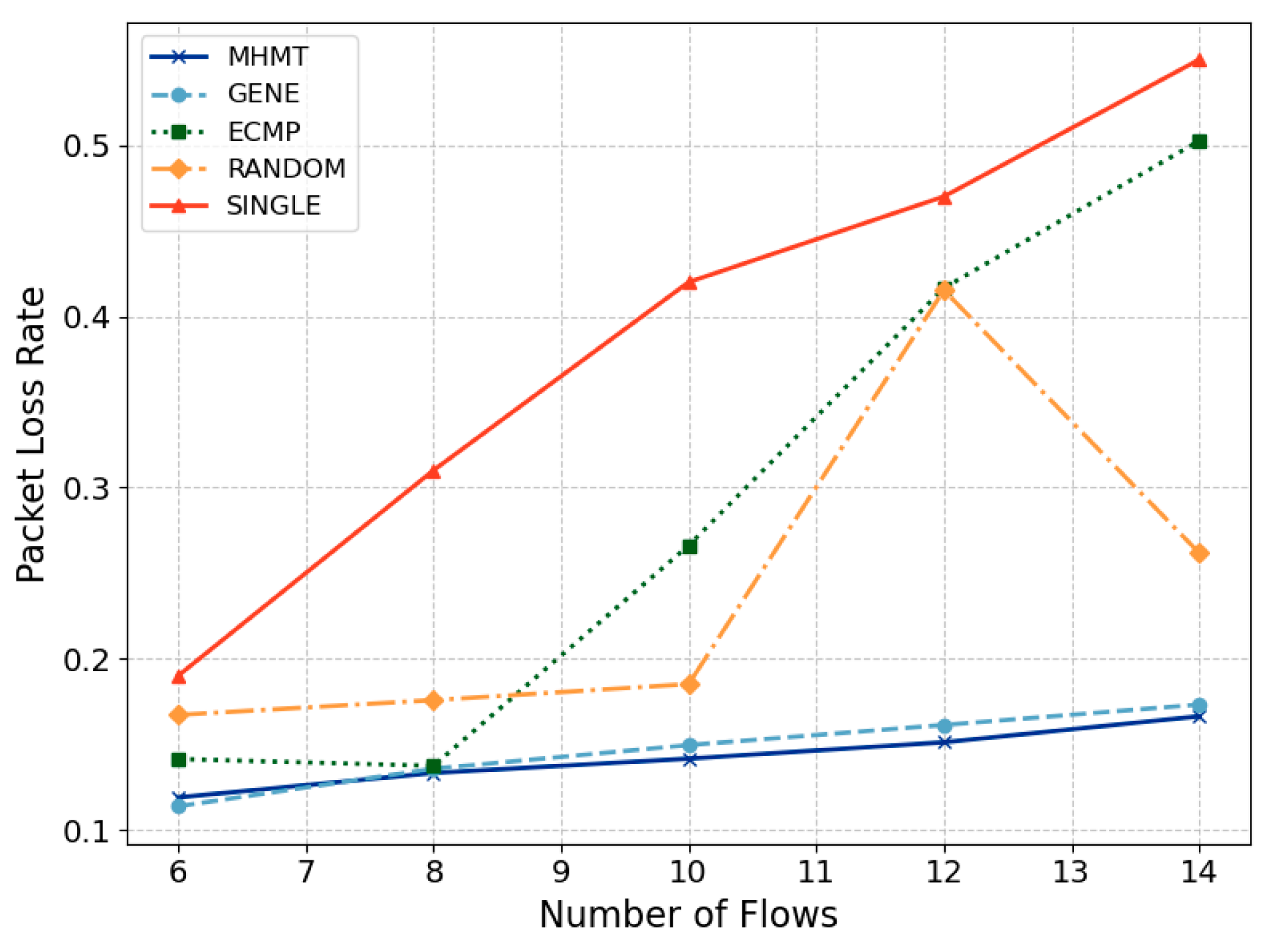
  • We implemented and tested the proposed MHMT method using the Mininet [3] network simulator. Simulation results show that MHMT achieves a near-optimal solution with significantly lower time overhead compared to the genetic algorithm, requiring only 7 milliseconds versus 4.7 s for 14 data flows. Compared to ECMP, random selection, and single-path methods, MHMT outperforms in terms of average packet transmission delay, QoS satisfaction rate, average packet loss rate, and throughput. Specifically, with 14 data flows, MHMT reduces average packet delay by 45%, packet loss rate by 66%, and increases throughput by 126% compared to ECMP.
The structure of this paper is as follows: Section 2 reviews existing research on mobility support and multipath routing. Section 3 presents the architecture of a mobile communication system and describes the mobility support process. Additionally, a multi-topology selection model is introduced. Section 4 provides a detailed description of the method and algorithm. In Section 5, experimental analysis is conducted, comparing the performance of MHMT with other methods. Finally, Section 6 offers a summary and outlook for future work.

2. Related Work

In this section, we review related work on mobility support methods and discuss research related to multipath routing.

2.1. Mobility Support Methods

Mobility support in wired networks maintains connectivity as users move between networks. Various methods have been proposed to manage IP mobility. Early solutions, such as Mobile IP (MIP) [4], retain a home IP address but suffer from triangular routing inefficiencies. Mobile IPv6 (MIPv6) [5] and Hierarchical Mobile IPv6 (HMIPv6) [6] introduce Home Agents (HA) and Mobility Anchor Points (MAPs) to reduce latency but still face path extension issues. Proxy Mobile IPv6 (PMIPv6) [7] shifts mobility management to the network layer using Local Mobile Anchors (LMA) and Mobile Access Gateways (MAG), but fixed anchors remain a limitation.
Information-Centric Networking (ICN) uses names instead of IP addresses for routing. Mobility support in ICN can be categorized into anchor-based and anchorless approaches. Anchor-based methods redirect requests through fixed nodes, as seen in the schemes by Hermans et al. [8], Zhang et al. [9], and Kim et al. [10]. However, anchor-based methods often result in triangular routing inefficiencies. They also face scalability issues. Anchorless approaches eliminate fixed anchors and dynamically switch paths based on producer movement. Examples include MAP-ME [11] and OPMSS [12], which optimize data paths effectively. However, these methods suffer from broadcast signaling overhead and topology-specific inefficiencies. Other advanced methods, including MobilityFirst [13] and those by Sun et al. [14], Gao et al. [15], and Azgin et al. [16], use unique identifiers and name resolution systems for seamless mobility but are less effective for low-latency scenarios.
These methods select a single switching path for all mobile data flows. However, relying on a single switching path may fail to accommodate the diverse requirements of all mobile data flows.

2.2. Multipath Routing in Non-Mobility Contexts

Multipath routing has been widely studied to enhance load balancing and resource utilization across networks. However, existing multipath routing methods face two main limitations for mobility support. First, their time consumption is too high, making them unsuitable for mobility scenarios that require minimal handover delays. Second, they do not consider the varying QoS requirements of data flows, which may result in path allocations that fail to meet specific QoS demands for each flow.
Multipath TCP (MPTCP) [17] is a transport layer solution that splits a single data flow into multiple subflows sent across different paths to optimize resource utilization. However, MPTCP suffers from packet reordering, which is time-consuming and therefore unsuitable for mobility scenarios. Routing layer solutions, such as ECMP (Equal-Cost Multi-Path) [18] and WCMP (Weighted-Cost Multi-Path) [19], distribute flows across multiple paths based on a hash of the source IP address. They avoid packet reordering. However, these approaches also do not consider the varying bandwidth or delay requirements of data flows, limiting their effectiveness. Other approaches focus on improving network throughput without specifically addressing QoS differentiation. Tague et al. [20] proposed a flow allocation algorithm based on jamming statistics to improve network throughput. Lee et al. [21] introduced a distributed secure multipath routing algorithm to optimize traffic allocation. To address varying QoS requirements, Pei et al. [22] proposed a dynamic Service Function Chaining (SFC) approach. However, this method has high time complexity, making it impractical for mobility scenarios. Kamboj et al. [23] developed a QoS-aware dynamic multipath routing scheme, but the method introduces significant delays due to packet reordering.
Multi-topology routing [24] is one approach to achieve multipath routing. Within a physical topology, several logical topologies can be generated. Each logical topology is a subset of the physical topology. This enables rapid path switching, which enhances flexibility and efficiency. The challenge in implementing multi-topology routing can be divided into two aspects.
The first focus is on establishing multi-topologies. Menth et al. [25] proposed enhancing network reliability through multi-topology routing, ensuring that there are backup topologies available to restore routing in case of link failures. RFC 4951 introduces relevant standards for OSPF multi-topology routing, indicating the construction of multi-topology routes by including MT-ID information in the TOS field of LSA during link discovery. Bhandari et al. [26] suggested using gray relational analysis (GRA) to address the issue. The goal is to select the optimal parent node based on multiple routing metrics. The weights of these metrics are determined by a standard deviation approach. These methods are all based on creating paths from scratch, which incurs significant computational overhead and is unsuitable for mobility scenarios.
The second focus is on allocating data flows across multiple paths. Demir et al. [27] proposed a multi-topology traffic optimization approach. This method assigns paths for delay-sensitive TT streams and AVB streams. It uses heuristic algorithms to find optimal solutions. Pop et al. [28] developed a model that considers worst-case delay analysis. This model accurately evaluates the timing characteristics of routing candidates. However, both methods suffer from high time complexity. Mehmood et al. [29] suggested a primary and backup path classification for critical and normal flows to improve throughput. However, this binary classification is overly simple, making it difficult to categorize various flows.
In summary, existing multi-topology routing methods are limited by high time complexity, insufficient attention to varying QoS requirements, and issues with path overlaps. Therefore, a new flow allocation algorithm is needed to improve efficiency.

3. System and Scenario Description

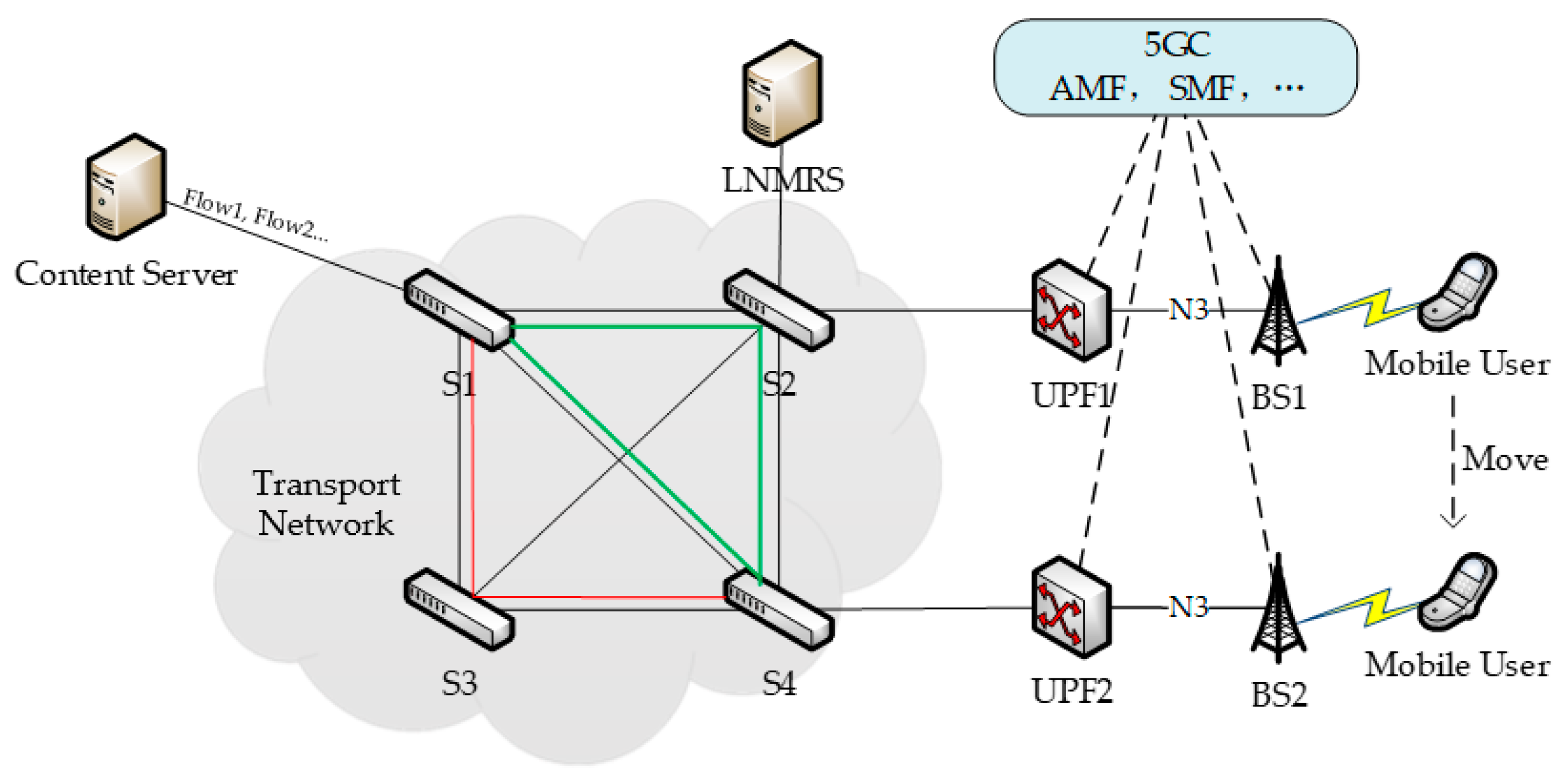
3.1. Architecture Overview

The MHMT method is based on the On-Site, Elastic, Autonomous Network (SEANet) [30]. It functions as an overlay network on top of the IP network, ensuring compatibility with IP. SEANet provides a local name mapping and resolution system (LNMRS), which maintains the mapping between the mobile user’s entity identifier (EID) and their current network address (NA). As illustrated in Figure 1, we consider a mobile communication system that includes a content server, switches, base stations (BSs), and mobile users. Additionally, LNMRS provides resolution services to switches with deterministic response delays. This system can collaborate with the 5G core network (5GC). The possible relationship between this system and the 5GC is also depicted. In 5G networks, the User Plane Function (UPF) manages user plane data forwarding. When a user switches to another UPF, its network address should be changed.
The black lines form the physical topology. The green lines represent one logical topology, and the red lines represent another. It can be seen that the green topology includes switches S1, S2, S4 and connections (S1, S2), (S1, S4), and (S2, S4), while the red topology includes switches S1, S3, S4 and connections (S1, S3) and (S3, S4). The content server connects to switch S1 through a wired connection, while the mobile user accesses the network through a base station.
Since this paper focuses on mobility support, it assumes that the connection setup and service requests have already been completed. The content server sends multiple data flows to the mobile user. Each packet in these flows contains a source EID (content identifier), a destination EID (mobile user identifier), and a destination NA (mobile user’s network address). Each data flow is uniquely identified by the combination of its source and destination EIDs. When the mobile user moves and its network address changes, the content server is unaware of this change. As a result, the network addresses in the packets do not change, leading to a failure in data transmission to the mobile user’s new location.
The switch can query the LNMRS to obtain the mobile user’s current network address using the destination EID. Each switch maintains a mobility management flow table, which consists of a set of mobility management entries. These entries store the source EID, destination EID, and the latest network address (NA), corresponding to the destination EID.
When a data packet arrives, the switch first looks up the mobility management flow table for a matching entry by comparing the source and destination EIDs. If a match is found, the switch replaces the outdated destination NA in the packet with the current destination NA. Then, it uses the Forwarding Information Base (FIB) to forward the packet. This procedure is called late-binding. If no matching entry is found, the switch directly forwards the packet according to the FIB. It is noted that if a switch belongs to multiple logical topologies, it will maintain multiple corresponding FIB tables.
We present the mobility support process as follows.
Step 0: Initially, the mobile user is located within the coverage area of BS1. The content server sends F data flows simultaneously to the mobile user across the physical topology. These flows are denoted as Flow 1, Flow 2, …, Flow F, and the transmission path is as follows: content server → S1 → S2 → UPF1 → BS1 → mobile user. The packets carry the source EID (content identifier), destination EID (mobile user identifier, EID0), and destination NA (mobile user’s network address, NA1). In addition, the packets also carry the corresponding sending rates and the transmission delay requirements for the content;
Step 1: When the mobile user moves into the coverage area of BS2, switch S2 can perceive this change through some mechanism, although the method of perception is not the focus of this study. The information includes the mobile user’s identifier (EID0), the identifiers of the requested content (EID1, EID2, …, EIDF), as well as the corresponding sending rates and the transmission delay requirements for each content;
Step 2: Switch S2 queries the LNMRS to obtain the current network address of the mobile user associated with EID0;
Step 3: Switch S2 receives the response from the LNMRS, obtaining the mobile user’s new network address, NA2;
Step 4: Switch S2, acting as a late-binding node, redirects packets intended for the user EID0 by modifying the destination NA from NA1 to NA2. This ensures that, even if other nodes have not completed the late-binding, the packets can be forwarded to the new address. At the same time, switch S2 generates a mobility announcement message that travels back along the original data transmission path to S1. This announcement message includes the following: EID0 and its new network address NA2, identifiers of the requested content (EID1, …, EIDF), data flow rates, and the transmission delay requirements for each content;
Step 5: Switch S1 receives the mobility announcement message and becomes aware of the user’s movement. Acting as a late-binding node, S1 redirects the data flows. Based on the current network conditions and the specific requirements of each data flow, S1 selects an appropriate logical topology for each data flow for subsequent transmission. If only a single switching path is allowed, the rerouted data flows follow the shortest path in the physical topology: content server → S1 → S4 → UPF2 → BS2 → mobile user. However, if multi-topology can be used, part of the data flows can be transmitted along content server → S1 → S4 → UPF2 → BS2 → mobile user (green topology), while another part can be transmitted along content server → S1 → S3 → S4 → UPF2 → BS2 → mobile user (red topology).

3.2. Problem Description and Formulation

In the context of multi-topology routing, as illustrated in Figure 2, diagram (a) represents the physical topology G ( V , E ) , where each link has a bandwidth of c e ( e E ) . Diagrams (b), (c), and (d) represent three logical topologies generated from the physical topology. Each logical topology G ( V , E ) is a subset of the physical topology, meaning that V V ,   E E .
The content server is connected to Node B, while the mobile user accesses the network through Node A. The mobile user requests multiple content, resulting in F data flows being transmitted from Node B to Node A. The data transmission follows a continuous flow model, which means the traffic flow is sent at a fixed rate. The sending rate for each data flow f f F is denoted as v f . When the mobile user moves from Node A to Node D, if data transmission continues to rely on the physical topology, a shortest path routing algorithm will reroute all data flows to follow the path B → C → D. If the bandwidth on the link (C, D) is insufficient, such that c c d < f = 1 F v f , congestion will occur on the link (C, D), leading to an increased packet loss rate and a decline in user experience.
In a different scenario, if multi-topology routing is allowed, different delay requirements can be met for each content request. The maximum allowable delay for data flow f is denoted as D f ( f F ) . For real-time content, D f is relatively short, whereas for less time-sensitive content, such as files, D f   is comparatively longer. Initially, data transmission relies on logical topology T1. The content server is connected to Node B, while the mobile user accesses the network through Node A. The mobile user requests multiple content, resulting in F data flows sent from Node B to Node A.
When the mobile user moves from Node A to Node D, if data transmission continues within logical topology T1, the shortest path routing algorithm will reroute all data flows through the path B → A → F → D. The transmission delay increases significantly, potentially exceeding the maximum allowable delay D f for some flows. This leads to a failure to meet QoS requirements, causing a decline in user experience.
When a user’s network address changes, the key challenge is selecting suitable topologies for each data flow. This can be formulated as a mathematical model, specifically a 0–1 integer programming problem. Table 1 below summarizes the main symbols used in this paper and their descriptions.
The objective of this problem is to minimize both the average packet transmission delay and the average packet loss rate for the data flows, which constitutes a multi-objective optimization problem.
The transmission delay experienced by a packet consists of the following components [31].
T t r a n s = T p r o p + T p r o c e s s + T q u e u e
Propagation Delay ( T p r o p ): The time it takes for a packet to propagate through the transmission medium.
Processing Delay ( T p r o c e s s ): The time required for network devices, such as switches, to process the packet.
Queuing Delay ( T q u e u e ): When multiple packets are waiting to be processed by a network device, they enter a queue. Queuing delay is the time packets spend waiting in that queue.
Since the switch processing delay is typically in the microsecond range [32], it can be considered negligible. However, queuing delays depend on congestion levels, making it unpredictable. In our model, link bandwidth is a constraint to avoid congestion. Propagation delays mainly depend on the physical medium length and signal propagation speed. For simplicity, our model assumes that delays across links are uniform, and the packet transmission delay is solely dependent on the hop count of the path. Unlike long-term network resource allocation, mobility handover is a brief event. It occurs within tens of milliseconds. During such a short period, it is reasonable to assume that network conditions remain constant.
Therefore, to minimize the average packet transmission delay for the data flows, the problem can be reformulated as minimizing the average hop count per packet for all flows.
D ¯ = f = 1 F t = 1 T X f t h f t F
The average packet loss rate can be expressed as follows:
P f = t = 1 T X f t 1 e = 1 E 1 X e t P e
The average packet loss rate for all flows is as follows:
  P ¯ = f = 1 F P f F = t = 1 T X f t 1 e = 1 E 1 X e t P e F
Constraint 1:
t = 1 T X f t = 1 , f 1 , F
X f t = 0,1 , f 1 , F t 1 , T
That is, each flow can only be allocated to one topology.
Constraint 2:
  f = 1 F t = 1 T X f t X e t V f C e , e 1 , E
That is, the total sending rate of data flows on each link cannot exceed its bandwidth, in order to avoid congestion.
Constraint 3:
t = 1 T X f t h f t H f , f 1 , F
The hop count in the selected topology for each flow must not exceed its specified hop constraint. We translate the user’s low delay requirement for specific content into a hop constraint for the path within the selected topology for that data flow.
Since there are two optimization objectives that may conflict with each other, a common way to address such issues is by using the weighting method. It combines multiple objective functions into a single one, often by calculating a weighted sum. Another alternative is the Pareto optimization method [33], which aims to find a set of Pareto optimal solutions. A pareto optimal solution is one in which no other solution can improve all objectives simultaneously. However, this yields a set of solutions, while we require a unique solution in. Therefore, we apply the weighting method to our problem. First, we normalize the two objective functions, respectively:
D x = D x D m i n D m a x D m i n
P x = P x P m i n P m a x P m i n
Thus, the objective function can be written as follows:
O P T = w 1 D ¯ + w 2 P ¯
where
w 1 + w 2 = 1

4. Method and Algorithms

The problem has been modeled as a 0/1 integer programming problem with multiple constraints. Existing algorithms for solving such problems can be divided into two categories: The first category includes branch-and-bound. It has a time complexity of O ( 2 n ) , where n is the number of variables. Another method is dynamic programming. It has a time complexity of O ( n k ) , where k is the number of dimensions. The second category includes various heuristic algorithms. These algorithms typically do not have explicit time complexity bounds, and their convergence speed and solution quality vary significantly depending on their parameter settings. Due to the strict requirements for minimal handover delay in mobility support scenarios, the problem must be addressed with a solution that has low time complexity.

4.1. The Dual Problem of the Original Problem

In optimization theory, the principle of duality suggests that an optimization problem can be viewed from two perspectives: the “primal problem” and the “dual problem”. The solution to the dual problem provides a lower bound for the primal problem (assuming it is a minimization problem) [34]. In this work, we analyze the topology selection problem from the perspective of the dual problem.
Dual problem objective:
M a x i m i z e W = f = 1 F α f C e T β H f T γ
Constraint:
α f f = 1 F t = 1 T X e t V f T β t = 1 T h f t T γ w 1 h f t + w 2 1 e = 1 E 1 X e t P e F ,
f 1 , F ,   t 1 , T
where α f , β , and γ are dual variables. C e T and H f T are the transposed matrices of C e and H f , respectively. By constructing the dual problem, the issue can be transformed into maximizing the value of the dual variables, while satisfying constraints for each f and t .

4.2. Algorithm Description and Complexity Analysis

From the dual problem’s objective function, it can be found that to minimize average packet delay and packet loss rate while maximizing the value of the dual problem objective, the second and third terms should be minimized. This involves reducing the bandwidth utilization of topologies with high packet loss rates and hop counts, while increasing the bandwidth utilization of topologies with lower packet loss rates and hop counts. Additionally, for each data flow, we assign the topology with the higher hop count that satisfies the flow’s hop constraint.
Guided by this principle, we developed MHMT. The detailed description of the MHMT algorithm is as Algorithm 1:
Algorithm 1 Multi-topology selection algorithm
  1:
Input :   Flows ,   Topos ,   Network   ( A   List   of   Links ) ,   Weights   w 1   and   w 2
  2:
Output :   Flows   with   Topology   assigned
  3:
Main   Program :
  4:
for   t o p o   in   Topos   do
  5:
t o p o c o s t w 1 h t o p o h m i n h m a x h m i n + w 2 P t o p o P m i n P m a x P m i n
  6:
end   for
  7:
for   t o p o   in   sort   ( Topos ,   key = t o p o c o s t )   do
  8:
for   f l o w   in   sort   ( Flows ,   key = f l o w . m a x _ h o p s )   do
  9:
if   all   ( f l o w .   m a x _ h o p s   <   t o p o .   h o p s   for   t o p o   in   other   Topos )   then
10:
allocate _ flow   ( f l o w ,   t o p o ,   f l o w .   l o c k = T r u e )
11:
end   if  
12:
end   for
13:
for   f l o w   in   sort   ( remaining   Flows ,   key = f l o w .   r a t e )   do
14:
allocate _ flow   ( f l o w ,   t o p o )
15:
end   for
16:
end   for
17:
for   f l o w   in   sort   ( remaining   Flows ,   key = f l o w .   r a t e ,   ascending = False )   do
18:
t   find _ min _ available _ bandwidth _ topo   ( Topos )
19:
B w t   t .   a v a i l a b l e _ b a n d w i d t h
20:
f   find _ argmin _ flow   ( f l o w   in   Flows   if   f l o w .   t o p o = t )
21:
  a r g m i n f ( B w t + V f f l o w .   r a t e )
22:
  s . t . B w t + V f f l o w .   r a t e > 0 ,   f .   l o c k = F a l s e
23:
replace _ flow   ( flow _ in = f l o w ,   flow _ out = f )
24:
end   for  
25:
for   f l o w   in   replaced   Flows   do
26:
t   find _ min _ available _ bandwidth _ topo   ( Topos )
27:
B w t   t .   a v a i l a b l e _ b a n d w i d t h
28:
  a r g m i n t ( B w t )
29:
s . t . B w t f l o w .   r a t e > 0
30:
allocate _ flow   ( f l o w ,   t )
31:
end   for
32:
for   f l o w   in   remaining   Flows   do
33:
t   find _ argmin _ topo   ( Topos )
34:
  a r g m i n t ( f = 1 F X f t )
35:
allocate _ flow   ( f l o w ,   t )
36:
  end for
37:
  Return Flows
In the first phase of the algorithm, the goal is to allocate as many flows as possible to topologies with lower costs to maximize their utilization, which corresponds to reducing the second term in the dual problem’s objective. During this allocation process, flows for which no other topology can meet the hop constraint are selected and locked, preventing further reallocation. This step helps minimize the third term in the dual problem’s objective. The remaining flows are then prioritized based on smaller sending rates, which further increases the bandwidth utilization of the lower-cost topologies.
The second phase focuses on minimizing fragmented resource space by making strategic replacements. Flows with smaller sending rates are prioritized for replacement, thereby increasing the possibility of successfully finding suitable topologies for them afterwards.
In the third phase, the remaining flows are allocated to the topology with the fewest existing data flows. This approach helps to minimize the impact on other data flows and prevent large-scale congestion caused by the addition of remaining flows.
The overall time complexity of the algorithm is O ( F × T ) , where F is the number of data flows and T is the number of logical topologies. Based on static multi-topology routing, the number of topologies T is a constant, so the time complexity is proportional to F .

5. Evaluation

5.1. Simulation Setup

This section presents a series of experiments aimed at evaluating the performance of MHMT. Five metrics are used to assess the performance: average packet transmission delay, QoS satisfaction rate, average packet loss rate, throughput, and handover delay. We developed MHMT and compared it with three multi-topology selection methods for path switching: the ECMP algorithm, a random selection method, and a genetic algorithm [35]. The solution provided by the genetic algorithm is treated as a near-optimal solution. ECMP serves as the baseline method for switching across multiple paths. Additionally, we implemented a single-path switching method as another baseline. This single-path approach selects the shortest path from the content server to the new destination node. The experimental platform is built on an Ubuntu 20.04 system. This platform includes Mininet 2.3.0 [3], Open vSwitch 2.17.9, and Ryu 4.34 [36]. Mininet is a network simulator that creates a virtual network of hosts, switches, and links on a single machine. Unlike other network simulators such as OMNeT++ [37] and NS-3 [38], Mininet transmits real data packets. It is widely used for testing software-defined networking (SDN). We repeated each set of experiments three times and took the average of the results.

5.1.1. Network Parameters

Network topologies typically include bus, star, tree, ring, and mesh structures. Since our study assumes multiple paths between the same node pairs, we selected mesh networks as the experimental topology. As shown in Figure 3, We created a random topology consisting of eight nodes and eleven links.
Based on the physical topology, five logical topologies were then randomly generated, as shown in Figure 4 below:
The packet loss rate for each link is set to a range between 0.05 and 0.1, uniformly distributed, and the bandwidth for each link is set to 12 Mbps. The packet queue size is set to five packets. The transmission delay for each link is set to 5 milliseconds. Host H1 is connected to switch S1, simulating the content server. Host H3 is connected to switch S3, simulating the mobile user before moving, and host H2 is connected to switch S2, simulating the mobile user after moving. H3 can send a mobility message to S3 to trigger the mobility management process. The message includes the mobile user’s identifier (EID0), its new network address (NA2, the IP address of H2), the requested content identifiers (EID1, …, EIDF), as well as the sending rate of each content and transmission delay requirements (hop constraints) for each content.
Initially, the content server sends multiple data flows to the mobile user via S1 and S3. After 1 s, the mobility management process is triggered by a mobility message sent by H3. Among the five logical topologies, the paths from S1 to S2 are as follows: (S1-S3-S2), (S1-S4-S2), (S1-S4-S5-S2), (S1-S8-S4-S2), and (S1-S7-S6-S5-S2), with hop counts of 2, 2, 3, 3, and 4, respectively.

5.1.2. Flow Parameters

We simulated situations where a mobile user requests varying amounts of content by generating different numbers of data flows. Each data flow has a sending rate uniformly distributed between 1.6 Mbps and 3.2 Mbps, equivalent to 200 to 400 packets per second, with each packet being 1000 bytes in size. The sending rate represents the bandwidth requirement of the flow. Additionally, each data flow is assigned a hop constraint, which specifies the maximum number of hops allowed in its transmission path. These hop constraints are uniformly distributed between 2 and 4, considering only integer values. Data flows with smaller hop constraints (e.g., hop_constraint = 2) are regarded as latency-sensitive applications, such as VoIP, because their requirements demand shorter paths to minimize delay. In this way, different QoS-sensitive applications can be characterized by varying data flow parameters. Each data flow is randomly generated and independent of each other. The parameters for the generated data flows are shown in Table 2, using the format: Flow (content_identifier, sending_rate, hop_constraint).
Because the data flows have requirements for transmission delay, which is a constraint in our modeling, a higher weight is assigned to the packet loss rate for the two optimization objectives. In the MHMT algorithm, w 1 = 0.7 and w 2 = 0.3 . In the comparative algorithm, the parameters for the genetic algorithm are set as follows: the number of generations is 300, the population size is 10, and both crossover and mutation points are generated randomly. The selection algorithm for the next generation uses roulette wheel selection. The ECMP method employs modulo hashing, where the selected topology T f = ( f   m o d   t ) , with t representing the number of topologies with the shortest paths.

5.2. Simulation Results and Analyses

5.2.1. Average Packet Transmission Delay

By capturing packets from the ports of H1 and H2, we obtained the data packets sent by the content server and received by the mobile user after it moved. We calculated the time differences for all packets within each data flow to obtain the average packet transmission delay for each flow. Dividing by the number of data flows gives us the overall average packet transmission delay. Figure 5 shows the comparison of average packet transmission delays of different algorithms against the number of content requested by a mobile user.
When the number of flows is six and eight, all methods, including MHMT, GENE, ECMP, and RANDOM, show comparable average packet delays, as there are sufficient bandwidth resources to meet the demands. The SINGLE method, however, already starts with a higher delay at six flows. Under the experimental setup, both Topology 1 and Topology 2 have a shortest path length of 3, allowing the ECMP method to distribute data flows evenly between these two topologies without causing congestion. Both MHMT and GENE make topology selections based on packet loss rates and path lengths, while RANDOM selects topologies arbitrarily, which leads to higher delays. SINGLE exhibits the highest delay due to its reliance on a single path. The bandwidth of this single path is insufficient to accommodate all flows, leading to congestion and a significant increase in packet delay.
When the number of flows increases to 10 and 12, the performance of MHMT and GENE remains relatively stable, with a slight increase in average packet delay as they allocate some data flows to topologies with longer paths. In contrast, ECMP begins to experience congestion due to its allocation of flows to only Topology 1 and Topology 2, resulting in a sharp increase in packet delay. RANDOM also suffers from increased delays due to the longer paths it sometimes selects. The average packet delay of SINGLE peaks at around 45 ms and does not continue to increase, because the queue size reaches its limit and extra packets are directly dropped.
At 14 flows, network resources become insufficient to fully meet the demands of all data flows. As a result, all methods show increased average packet delays, but the extent of the increase varies. MHMT allocates the remaining data flows to the topology with the least flows, thereby minimizing congestion and maintaining lower average delays compared to the other methods. The GENE algorithm selects allocation schemes that minimize its objective function. ECMP continues with its selection, leading to severe congestion and the highest packet delays. RANDOM performs better than ECMP but still has high delays due to inefficient path selection.

5.2.2. QoS Satisfaction Rate

Figure 6 illustrates the QoS satisfaction rate for each algorithm as the number of data flows increases. The QoS satisfaction rate represents the percentage of data flows that meet the specified quality of service requirements, such as bandwidth and delay. Initially, both MHMT and GENE maintain high QoS satisfaction rates when the number of flows is low. As the number of flows increases beyond 12, the available bandwidth becomes insufficient, causing a decline in QoS satisfaction. ECMP experiences a rapid decline in QoS satisfaction as the number of flows exceeds 10, since it always distributes flows equally across Topologies 1 and 2 without considering bandwidth constraints. This results in significant congestion and a sharp reduction in performance. The RANDOM method, due to its arbitrary path selection, exhibits erratic QoS satisfaction rates. It occasionally performs well but often fails to select optimal paths, leading to increased congestion and inconsistent performance. SINGLE consistently shows the lowest QoS satisfaction rate across all flow counts. This is because SINGLE relies on a single path, which cannot accommodate all the flows, resulting in persistent congestion and poor performance.
Overall, MHMT stands out by achieving the most stable and highest QoS satisfaction rates as the traffic increases. This highlights its ability to allocate flows effectively and maintain service quality under varying network conditions.

5.2.3. Average Packet Loss Rate

The packet loss rate for each data flow is determined by dividing the number of packets received by H2 by the total number of packets sent by H1. The overall average packet loss rate is then obtained by averaging these rates across all data flows. Figure 7 presents the changes in average packet loss rates for the five algorithms as the number of data flows increases.
As the number of data flows increases, the performances of the MHMT and GENE algorithms are similar, with both exhibiting a gradual rise in packet loss rates. Specifically, MHMT’s packet loss rate increases from 0.119 to 0.166. In contrast, the ECMP algorithm continues to allocate all data flows to Topology 1 and Topology 2, which works well when the flow count is small. However, as the number of data flows reaches 10, congestion starts to occur, significantly raising the packet loss rate. When the flow count reaches 14, the packet loss rate for ECMP peaks at 50%, which is three times that of MHMT. The RANDOM and SINGLE algorithms show even worse performance. SINGLE consistently exhibits the highest packet loss rates across all flow counts due to relying on a single path that cannot handle all the flows. The RANDOM algorithm’s packet loss rate varies widely as it arbitrarily selects topologies.
Overall, MHMT manages to consistently achieve low packet loss rates due to its effective topology selection strategy that prioritizes both QoS and bandwidth availability

5.2.4. Handover Delay Analysis

The handover delay is calculated by comparing the time difference between the last packet received by H3 and the first packet received by H2. Since the mobility message includes the mobile user’s new network address, the resolution query process is omitted. The handover delay primarily consists of the communication delay between the controller and the switches, as well as the runtime of the multi-topology selection algorithm. Figure 8 shows the variation in handover delays for different algorithms as the number of data flows increases.
The genetic algorithm’s long runtime results in handover delays of several seconds, significantly longer compared to the other methods. As seen in Figure 8, the handover delays for ECMP and RANDOM do not change significantly as the number of flows increases, due to their time complexity of O ( F ) . Meanwhile, the handover delay of the MHMT algorithm shows a slight increase but remains below 20 milliseconds, even as the number of data flows grows from 6 to 14. Theoretically, the time complexity of MHMT is O ( F × T ) . When the number of topologies T is fixed, the time complexity increases linearly with the number of data flows F . Therefore, MHMT exhibits a similar handover delay to ECMP and RANDOM.

5.2.5. Algorithm Runtime Analysis

When evaluating the handover delay, we should consider factors such as packet size and transmission rate. With a packet size of 1000 bytes and a transmission rate ranging from 1.6 to 3.2 Mbps, the time interval for packet transmission falls between 2.5 and 5 milliseconds. A specific packet loss rate was introduced on each link, meaning that if the first packet sent after the user moves is lost, the calculated delay may overestimate the actual handover delay. To more accurately assess the runtime of the proposed algorithm and its relationship with the number of data flows, the runtime was measured separately, as shown in Figure 9.
The runtime of the MHMT algorithm increases linearly with the number of data flows. Since MHMT has a time complexity of O ( F × T ) , where F is the number of data flows and T is the number of logical topologies. The complexity increases linearly with the number of data flows. This low complexity, compared to most heuristic algorithms, makes MHMT suitable for mobility scenarios with strict handover delay requirements.

5.2.6. Throughput

Figure 10 compares the throughput (in KB/s) of five methods as the number of flows increases from 6 to 14. MHMT consistently achieves the highest throughput, except at six flows where it is slightly lower than GENE. At 14 flows, it peaks at 2898.165 KB/s, indicating its robustness under high traffic loads. This throughput is 66% higher than ECMP and 128% higher than SINGLE.

6. Discussion

This study introduces a novel mobility handover decision method based on multi-topology (MHMT). It is designed to improve QoS satisfaction during mobility handovers in wired networks. Our results show that MHMT outperforms traditional single-path methods and existing multipath routing approaches like ECMP and random selection.
MHMT outperforms in terms of average packet transmission delay, QoS satisfaction rate, average packet loss rate, and throughput. MHMT significantly enhances QoS satisfaction by dynamically allocating data flows across multiple topologies. This also helps reduce packet loss and increase throughput by avoiding congestion. Furthermore, MHMT enables rapid path switching without the need to recalculate routes during the mobility handover. Its low computational complexity ensures that it can achieve low, acceptable handover delays. These features make MHMT a flexible and robust solution for mobility scenarios.
Existing multipath routing methods either introduce delays due to packet reordering and rerouting or fail to account for varying QoS requirements. MHMT dynamically selects paths based on network conditions and QoS requirements. This ensures better performance during handovers. Table 3 shows a comparison of MHMT with existing multipath routing methods.
In conclusion, MHMT offers a promising solution to the challenges of mobility handover in wired networks. Integrating MHMT with 5G networks would help extend MHMT’s capabilities. It provides the potential to address the growing demands of next-generation networks. However, the performance of MHMT is closely dependent on the structure of the logical topologies. Further research is needed to explore how to design more efficient multi-topology. Additionally, our method assumes that network link quality and the traffic in the network remain constant during the handover process. However, in real-world networks, these parameters can change rapidly, even within tens of milliseconds. If there are significant traffic fluctuations during the brief handover period, it could lead to inaccuracies in the input parameters for MHMT. This highlights the need for real-time monitoring with higher frequency to track such dynamic changes and provide timely feedback to MHMT. This represents an area for future research and development.

7. Conclusions

This paper proposes a novel mobility handover decision method based on multi-topology (MHMT) to address the challenge of maintaining the quality of services after mobility handovers. By dynamically allocating data flows across multiple logical topologies, MHMT effectively overcomes the limitations of single-path switching methods. The problem is modeled as an optimization task aimed at minimizing average packet transmission delay and average packet loss rate, while meeting diverse bandwidth and delay requirements. Simulation results show that MHMT outperforms traditional methods (including single-path switching, ECMP, and random selection) across key metrics like average packet transmission delay, QoS satisfaction rate, packet loss rate, and throughput. MHMT achieves a near-optimal solution, while significantly reducing handover delay compared to the genetic algorithm.
In conclusion, this study introduces a new perspective on mobility handover in wired networks. Future research could focus on dynamically adjusting multi-topology routing based on traffic variations to achieve higher levels of automation and intelligence.

Author Contributions

Conceptualization, C.Z. and R.H.; investigation, C.Z.; methodology, C.Z.; software, C.Z.; validation, C.Z.; writing—original draft preparation, C.Z.; writing—review and editing, H.D. and R.H.; supervision, H.D. and R.H. All authors have read and agreed to the published version of the manuscript.

Funding

This work was funded by the Basic and Frontier Exploration Project independently deployed by the Institute of Acoustics, Chinese Academy of Sciences: Research on Wide-Area RDMA Transmission Acceleration Technology Based on SEANet (Project No. JCQY202407).

Data Availability Statement

All of the necessary data are included in the article.

Acknowledgments

We would like to express our gratitude to Haojiang Deng and Rui Han for their meaningful support for this work.

Conflicts of Interest

The authors declare no conflicts of interest.

References

  1. James, J.H.; Chen, B.; Garrison, L. Implementing voip: A voice transmission performance progress report. IEEE Commun. Mag. 2004, 42, 36–41. [Google Scholar] [CrossRef]
  2. Xing, M.; Deng, H.; Han, R. ICN-Oriented Mobility Support Method for Dynamic Allocation of Mobile Data Flows. Electronics 2023, 12, 1701. [Google Scholar] [CrossRef]
  3. Mininet. Available online: http://mininet.org/ (accessed on 26 November 2024).
  4. Perkins, C.E. Mobile ip. IEEE Commun. Mag. 1997, 35, 84–99. [Google Scholar] [CrossRef]
  5. Perkins, C.; Johnson, D.; Arkko, J. Mobility Support in IPv6. RFC 6275. Available online: https://www.rfc-editor.org/rfc/rfc6275 (accessed on 26 November 2024).
  6. Soliman, H.; Castelluccia, C.; ElMalki, K.; Bellier, L. Hierarchical Mobile IPv6 (HMIPv6) Mobility Management. RFC 5380. Available online: https://www.rfc-editor.org/rfc/rfc5380 (accessed on 26 November 2024).
  7. Gundavelli, S.; Leung, K.; Devarapalli, V.; Chowdhury, K.; Patil, B. Proxy Mobile IPv6. RFC 5213. Available online: https://www.rfc-editor.org/rfc/rfc5213 (accessed on 26 November 2024).
  8. Hermans, F.; Ngai, E.; Gunningberg, P. Mobile Sources in an Information-Centric Network with Hierarchical Names: An Indirection Approach. In Proceedings of the 7th Scandinavian Networking Conference (SNCNW), Linköping, Sweden, 13–14 June 2011. [Google Scholar]
  9. Zhang, Y.; Zhang, H.; Zhang, L. Kite: A Mobility Support Scheme for NDN. In Proceedings of the ACM Conference on Information-Centric Networking, Paris, France, 24–26 September 2014; pp. 125–136. [Google Scholar]
  10. Kim, D.; Ko, Y.B. On-demand anchor-based mobility support method for named data networking. In Proceedings of the 2017 19th International Conference on Advanced Communication Technology (ICACT), Pyeongchang, Republic of Korea, 30 March 2017; pp. 19–23. [Google Scholar]
  11. Augé, J.; Carofiglio, G.; Grassi, G.; Muscariello, L.; Pau, G.; Zeng, X. Map-me: Managing anchor-less producer mobility in content-centric networks. IEEE Trans. Netw. Serv. Manag. 2018, 15, 596–610. [Google Scholar] [CrossRef]
  12. Hussaini, M.; Naeem, M.A.; Kim, B.S. Opmss: Optimal producer mobility support solution for named data networking. Appl. Sci. 2021, 11, 4064. [Google Scholar] [CrossRef]
  13. Raychaudhuri, D.; Nagaraja, K.; Venkataramani, A. Mobilityfirst: A robust and trustworthy mobility-centric architecture for the future internet. ACM Sigmobile Mob. Comput. Commun. Rev. 2012, 16, 2–13. [Google Scholar] [CrossRef]
  14. Sun, Y.; Zhou, J.; Hu, B.; Zhou, X.; Song, W.; Li, M.; Tian, Z. Hierarchical Name-based Routing for Content Provider Mobility in ICN. In Proceedings of the 2023 International Wireless Communications and Mobile Computing (IWCMC), Marrakesh, Morocco, 21 July 2023; pp. 941–946. [Google Scholar]
  15. Gao, S.; Zhang, H. Scalable mobility management for content sources in Named Data Networking. In Proceedings of the 2016 13th IEEE Annual Consumer Communications & Networking Conference (CCNC), Las Vegas, NV, USA, 9–12 January 2016; pp. 79–84. [Google Scholar]
  16. Azgin, A.; Ravindran, R.; Chakraborti, A.; Wang, G.Q. Seamless producer mobility as a service in information centric networks. In Proceedings of the 3rd ACM Conference on Information-Centric Networking, Kyoto, Japan, 26–28 September 2016; pp. 243–248. [Google Scholar]
  17. Ford, A.; Raiciu, C.; Handley, M.; Bonaventure, O. TCP Extensions for Multipath Operation with Multiple Addresses. RFC 6824. Available online: https://www.rfc-editor.org/rfc/rfc6824.html (accessed on 26 November 2024).
  18. Hopps, C. Analysis of an Equal-Cost Multi-Path Algorithm. RFC 2992. Available online: https://www.rfc-editor.org/rfc/rfc2992.html (accessed on 26 November 2024).
  19. Zhou, J.; Tewari, M.; Zhu, M.; Kabbani, A.; Poutievski, L.; Singh, A.; Vahdat, A. WCMP: Weighted cost multipathing for improved fairness in data centers. In Proceedings of the Ninth European Conference on Computer Systems, Amsterdam, The Netherlands, 14–16 April 2014; pp. 1–14. [Google Scholar]
  20. Tague, P.; Nabar, S.; Ritcey, J.A.; Poovendran, R. Jamming-aware traffic allocation for multiple-path routing using portfolio selection. IEEE/ACM Trans. Netw. 2010, 19, 184–194. [Google Scholar] [CrossRef]
  21. Lee, P.P.; Misra, V.; Rubenstein, D. Distributed algorithms for secure multipath routing in attack-resistant networks. IEEE/ACM Trans. Netw. 2007, 15, 1490–1501. [Google Scholar] [CrossRef]
  22. Pei, J.; Hong, P.; Xue, K.; Li, D. Resource aware routing for service function chains in SDN and NFV-enabled network. IEEE Trans. Serv. Comput. 2018, 14, 985–997. [Google Scholar] [CrossRef]
  23. Kamboj, P.; Pal, S.; Bera, S.; Misra, S. QoS-aware multipath routing in software-defined networks. IEEE Trans. Netw. Sci. Eng. 2022, 10, 723–732. [Google Scholar] [CrossRef]
  24. Psenak, P.; Mirtorabi, S.; Roy, A.; Nguyen, L.; Pillay-Esnault, P. Multi-topology (MT) routing in OSPF. RFC 4915. Available online: https://www.rfc-editor.org/rfc/rfc4915.html (accessed on 26 November 2024).
  25. Menth, M.; Martin, R. Network resilience through multi-topology routing. In Proceedings of the Fifth International Workshop on Design of Reliable Communication Networks, Naples, Italy, 16–19 October 2005; pp. 271–277. [Google Scholar]
  26. Bhandari, K.S.; Ra, I.H.; Cho, G. Multi-topology based QoS-differentiation in RPL for internet of things applications. IEEE Access 2020, 8, 96686–96705. [Google Scholar] [CrossRef]
  27. Demir, Ö.K.; Cevher, S. Multi-Topology Routing based traffic optimization for IEEE 802.1 Time Sensitive Networking. Real-Time Syst. 2023, 59, 123–159. [Google Scholar] [CrossRef]
  28. Pop, P.; Raagaard, M.L.; Craciunas, S.S.; Steiner, W. Design optimisation of cyber-physical distributed systems using IEEE time-sensitive networks. IET Cyber-Phys. Syst. Theory Appl. 2016, 1, 86–94. [Google Scholar] [CrossRef]
  29. Mehmood, G.; Khan, M.Z.; Bashir, A.K.; Al-Otaibi, Y.D.; Khan, S. An efficient QoS-based multi-path routing scheme for smart healthcare monitoring in wireless body area networks. Comput. Electr. Eng. 2023, 109, 108517. [Google Scholar] [CrossRef]
  30. Wang, J.; Chen, G.; You, J.; Sun, P. SEANet: Architecture and Technologies of an On-site, Elastic, Autonomous Network. J. Netw. New Media 2020, 9, 1–8. [Google Scholar]
  31. Papagiannaki, K.; Moon, S.; Fraleigh, C.; Thiran, P.; Diot, C. Measurement and analysis of single-hop delay on an IP backbone network. IEEE J. Sel. Areas Commun. 2003, 21, 908–921. [Google Scholar] [CrossRef]
  32. Ramaswamy, R.; Weng, N.; Wolf, T. Characterizing network processing delay. In Proceedings of the IEEE Global Telecommunications Conference, 2004, GLOBECOM’04, Dallas, TX, USA, 29 November–3 December 2004; pp. 1629–1634. [Google Scholar]
  33. Censor, Y. Pareto optimality in multiobjective problems. Appl. Math. Optim. 1977, 4, 41–59. [Google Scholar] [CrossRef]
  34. Boyd, S.; Vandenberghe, L. Convex Optimization; Cambridge University Press: Cambridge, UK, 2004; ISBN 978-0-521-83378-3. [Google Scholar]
  35. Mitchell, M. An Introduction to Genetic Algorithms; MIT Press: Cambridge, MA, USA, 1998; ISBN 978-0-262-53237-6. [Google Scholar]
  36. Ryu Controller. Available online: https://github.com/faucetsdn/ryu (accessed on 2 December 2024).
  37. Varga, A.; Hornig, R. An overview of the OMNeT++ simulation environment. In Proceedings of the 1st International ICST Conference on Simulation Tools and Techniques for Communications, Networks and Systems, Marseille, France, 3–7 March 2008. [Google Scholar]
  38. Riley, G.F.; Henderson, T.R. The ns-3 Network Simulator. In Modeling and Tools for Network Simulation; Springer: Berlin/Heidelberg, Germany, 2010; pp. 15–34. [Google Scholar]
Figure 1. Mobile communication system with multi-topology.
Electronics 13 04777 g001
Figure 2. Physical topology and logical topologies. (a) Physical topology, (b) logical topology T1, (c) logical topology T2, and (d) logical topology T3.
Electronics 13 04777 g002
Figure 3. Physical topology of simulation.
Electronics 13 04777 g003
Figure 4. Logical topologies of simulation.
Electronics 13 04777 g004
Figure 5. Average packet transmission delay.
Electronics 13 04777 g005
Figure 6. QoS satisfaction rate.
Electronics 13 04777 g006
Figure 7. Average packet loss rate.
Electronics 13 04777 g007
Figure 8. Handover Delay.
Electronics 13 04777 g008
Figure 9. Runtime of MHMT.
Electronics 13 04777 g009
Figure 10. Throughput.
Electronics 13 04777 g010
Table 1. Summary of symbols.
SymbolDescription
X f t Boolean   variable ;   X f t = 1   if   flow   f   is   selected   for   forwarding   in   topology   t ;   otherwise ,   X f t = 0
X e t Boolean   variable ;   X e t = 1   if   link   e   is   included   in   the   shortest   path   from   the   source   node   to   the   new   access   node   within   topology   t ;   otherwise ,   X e t = 0 (input parameter)
C e Bandwidth   of   link   e (input parameter)
P e Packet   loss   rate   of   link   e , in the range of 0–1 (input parameter)
H f Hop   constraint   for   flow   f (mapping delay constraint to hop constraint) (input parameter)
V f Required   bandwidth   for   flow   f   ( sending   rate   of   flow   f ) (input parameter)
h f t Hop   count   for   the   packet   in   flow   f   along   the   shortest   path   in   topology   t  (input parameter)
T Total number of topologies (input parameter)
F Total number of flows to be allocated (input parameter)
P f Total   packet   loss   rate   for   flow   f
Table 2. Flows’ parameter.
Flow NumberParameters
6 Flow(1,2.4,3), Flow(2,1.6,4), Flow(3,3.2,2), Flow(4,1.6,3), Flow(5,2.4,4), Flow(6,3.2,4)
8 Flow(1,1.6,4), Flow(2,2.4,4), Flow(3,2.4,3), Flow(4,3.2,2), Flow(5,2.4,4), Flow(6,2.4,3), Flow(7,1.6,4), Flow(8,3.2,4)
10Flow(1,3.2,3), Flow(2,3.2,4), Flow(3,2.4,3), Flow(4,1.6,4), Flow(5,3.2,4), Flow(6,1.6,4), Flow(7,1.6,3), Flow(8,1.6,3), Flow(9,3.2,3), Flow(10,3.2,4)
12Flow(1,1.6,2), Flow(2,2.4,2), Flow(3,2.4,4), Flow(4,3.2,2), Flow(5,1.6,4), Flow(6,2.4,4), Flow(7,1.6,4), Flow(8,1.6,2), Flow(9,3.2,3), Flow(10,1.6,4), Flow(11,2.4,4), Flow(12,3.2,4)
14Flow(1,1.6,3), Flow(2,2.4,4), Flow(3,2.4,4), Flow(4,1.6,3), Flow(5,3.2,4), Flow(6,2.4,4), Flow(7,3.2,4), Flow(8,3.2,3), Flow(9,3.2,2), Flow(10,1.6,4), Flow(11,1.6,2), Flow(12,3.2,4), Flow(13,2.4,2), Flow(14,1.6,4)
Table 3. Comparison of MHMT with existing multipath routing methods.
MethodStrengthQoS-AwareComplexity
MHMT (Proposed)Rapid path switching, low complexity, High QoS satisfactionYes Low ,   O ( F × T )
MPTCPOptimizes resource utilizationNoHigh, due to packet reordering
ECMPSimple, well-establishedNo Low ,   O ( F )
WCMPBetter load balancing compared to ECMPNo Low ,   O ( F × T )
Tague et al.Improves throughput under heavy congestionNo High ,   O ( F × T 3 )
Lee et al.Optimizes traffic allocationNoHigh, due to the recomputing of routing
Pei et al. (Dynamic SFC)Addresses varying QoS for each flowYesHigh, due to the recomputing of routing
Kamboj et al.Addresses varying QoS for each subflowYesHigh, due to packet reordering
Disclaimer/Publisher’s Note: The statements, opinions and data contained in all publications are solely those of the individual author(s) and contributor(s) and not of MDPI and/or the editor(s). MDPI and/or the editor(s) disclaim responsibility for any injury to people or property resulting from any ideas, methods, instructions or products referred to in the content.

