Abstract
A capacitive wireless power transfer (CPT) system based on parity–time (PT) symmetry achieves constant output characteristics under distance variation without additionally increasing the system complexity of the control strategy, where the concept of PT symmetry is derived from quantum mechanics, and the systems satisfying PT symmetry are invariant under space and time inversion. However, the exact PT-symmetric region (i.e., strong coupling region) of the general system is limited by the symmetry of the structure and parameters. To overcome this limitation, a novel generalized parity–time (GPT)-symmetric CPT system is proposed in this article. According to the equivalent circuit method, the circuit model of the proposed system is built, and the transfer characteristics are analyzed. Furthermore, a prototype is implemented to verify the feasibility of the proposed CPT system. The results show that the PT-symmetric region is extended by 169.23% compared with the traditional PT-based CPT system, and a constant output power of 21.5 W is transferred with a constant transfer efficiency of 90%.
1. Introduction
Capacitive wireless power transfer (CPT) technology is a wireless charging technology that achieves energy transfer through the electric field coupling between metal plates [1,2,3]. It distinguishes itself in the realm of wireless power transfer due to its cost-effectiveness, lack of eddy current effects, light weight, and insensitivity to metal obstacles. Nowadays, CPT technology has found extensive applications across various fields, such as underwater equipment, implantable medical equipment, and electric vehicle charging, showcasing its robust potential for practical use [4,5,6,7,8,9].
It is still a crucial challenge for existing CPT technology to achieve constant output characteristics, such as constant current (CC), constant voltage (CV), constant output power, and invariable transfer efficiency. Therefore, when the transfer distance changes, ref. [10] proposes that a bilateral communication dual-loop control CPT system should be used to reduce the effect of coupling misalignment and load variation, which track the input and output voltage to realize frequency tuning. The authors of [11] present a reconfigurable capacitive coupler, which can be reconfigured according to the landing positions and directions and achieve constant output when misalignment tolerance is encountered. The authors of [12] adopt the method of the use of a dual transmitter and single receiver to achieve higher than 85% transfer efficiency under misaligned conditions, but this increases the topological complexity of the system. Meanwhile, [13] utilizes a fractional-order approach to achieve the strong robustness of the CPT system when the coupling coefficient changes from 0.45 to 0.75 and the resonant frequency detuning is within 5%, but the application of a fractional order increases the complexity of control under certain circumstances. The authors of [14] employ the LCLC-S/LCLC-M topology to achieve CC/CV output when misalignment happens in the x- (y-) or θ-direction, but this method increases the complexity of topology and control in certain circumstances and also increases cost. In addition, ref. [15] introduces a multiplate capacitive coupler structure that utilizes the characteristics of a six-plate structure to reduce the geometric sensitivity caused by the misalignment of the coupling plates, achieving a constant output power of 2.0 kW, but the design of the capacitive coupler is complex. The authors of [16] propose a frequency-agile mode and use frequency bifurcation to realize the constant output characteristics of the system at the secondary resonance, but this requires a more complex circuit topology and control strategy. The authors of [17] propose an LCLC-LC compensation structure; when the system load changes, the system operating frequency is switched to achieve constant output current or voltage, but when the system transmission distance changes, the constant transmission characteristics of the system may not be achieved. The authors of [18] present a class-E zero-voltage switching parallel resonant inverter and a class-D rectifier to realize constant output voltage without any feedback control loops, but when the load resistance is large, the transfer efficiency of the system is low and may not be applicable when the system is misaligned. The authors of [19] propose a 6.78 MHz class-E power amplifier to realize quasi-constant current output, but when the system transmission distance changes, the constant transmission characteristics of the system may not be achieved. Consequently, the above methods are not conducive to engineering implementation to a certain extent.
The concept of PT symmetry is derived from quantum mechanics, and the PT-symmetric system is invariant under parity (P) and time (T) reversal, where P-reversal means spatial inversion; T-reversal is time inversion. In 2017, Assawaworrarit introduced PT symmetry to the WPT system for the first time, which achieves constant transfer characteristics when the system structure and parameters satisfy the condition of PT symmetry [20]. This system does not increase the complexity of control or topologies. The authors of [21] introduce the parity–time (PT) symmetry principle into the CPT system, achieving constant output characteristics, which extend the application of PT-symmetric wireless power transfer systems from the magnetic field to the electric field.
Nevertheless, the existing PT-based CPT systems demand rigorous structural and parametric symmetry, and transfer distance is restricted within the exact PT-symmetric region [21,22]. Generalized parity–time (GPT) symmetry is a general form of PT symmetry, which has the characteristics of PT symmetry under asymmetric structures and parameters [23].
To increase the transfer distance of the constant output characteristics (i.e., exact PT-symmetric region) and flexibility of the PT-based CPT system, a novel GPT-based CPT system is proposed in this article. The proposed system is composed of an asymmetric series–parallel series (S–PS) structure, which can extend the exact PT-symmetric region and adjust the output power and transfer efficiency by varying the capacitive distribution ratio.
The rest of this article is organized as follows. In Section 2, the proposed GPT system is modeled by circuit theory, and the circuit equivalent principle is used to reduce the order of the system. The output characteristics of the system are analyzed, and the output characteristics of different capacitance and inductance ratios are plotted. The appropriate inductance and capacitance ratio is selected according to the output characteristic curve of the system and compared with the original PT-CPT system. In Section 3, a 21.5 w prototype is built to verify the feasibility of the proposed system. The output characteristics of the system and input and output waveforms are given and analyzed. In Section 4, some conclusions are given by combining theoretical analysis and experimental verification.
2. System Structure and Modeling
2.1. Capacitive Coupler
The capacitive coupler is the core component of the CPT system, and its equivalent circuit is shown in Figure 1a. Both CP1 and CP2 are constructed entirely from metal plates. The transmitting (Tx) and receiving (Rx) sides are coupled by the capacitances CP1 and CP2. Then, the mutual capacitance can be expressed as CM = CP1CP2/(CP1 + CP2) [24,25], and the further equivalent π-type circuit is shown Figure 1b.
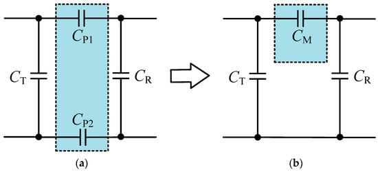
Figure 1.
Capacitive coupler. (a) Original circuit model. (b) Equivalent π-type circuit model.
2.2. GPT-Based CPT System with S-PS Structure
The GPT-based CPT system with S-PS structure topology is shown in Figure 2. Here, the power of the system is provided by the negative resistance −RN, which is constructed by the sampling circuit and full-bridge inverter on the Tx side, and the inverter is constructed by four MOSFETs (S1–S4). LT and LR are the resonant inductors on the Tx and Rx sides, respectively. CT and CR are the tuning capacitors on the Tx and Rx sides, respectively. CS1 and CS2 are series and parallel tuning capacitors on the Rx side. CM is the mutual capacitor between the Tx and Rx sides. rT and rR represent the internal resistances of the Tx and Rx sides, respectively. RL is the load resistance of the system. LT and LR are the inductances of the Tx and Rx sides, respectively. iT, iCM, iR, and iL are the currents through the Tx side, mutual capacitor, Rx side, and load, respectively. uT and uL are the input and output voltages of the system, respectively. UDC is the DC input voltage of the full-bridge inverter.
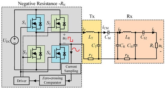
Figure 2.
Topology of GPT-based CPT system with S-PS structure.
Due to the fact that the quality factor of the CPT system is usually high, the current of the steady-state system can be considered as a sine wave. Therefore, the steady-state currents are analyzed by the fundamental wave method. iT, iCM, iR, and iL can be expressed as İT, İCM, İR, and İL by the vector method.
Then, the parallel capacitance at the Rx side increases the order of the system, which also brings great inconvenience to the modeling and calculation of the system. However, the equivalent circuit theory provides a theoretical method for reducing the order of a system, and the PS structure network at the Rx side can be equivalent to the S structure network, as shown in Figure 3.
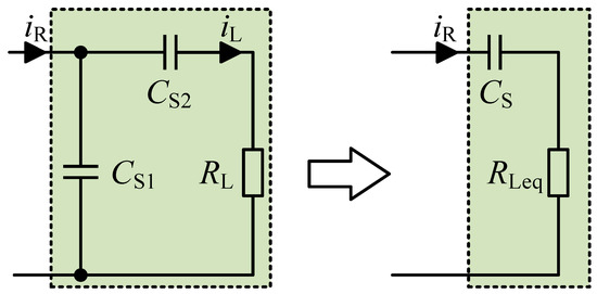
Figure 3.
The equivalent transformation of the load side.
The parameters of the equivalent S compensation topology are as follows:
According to the parameters of the general CPT system, and are satisfied, so (1) can be approximated as
Here, α is defined as the distribution ratio of equivalent capacitance to parallel capacitance, that is
Then, the equivalent load resistance can be expressed as
Therefore, the GPT-based CPT system with the S-PS compensation structure can be equivalent to the SS compensation structure, as shown in Figure 4. In order to quantify the relationship between system characteristics and circuit parameters, circuit theory (CT) is used to model the system, and the equivalent circuit equation can be written as follows:
where , ω is the operating angular frequency, and and are the natural resonant frequencies of the Tx and Rx sides. is the coupling coefficient between the Tx and Rx plates. It is noted that the proposed system needs to ensure that the natural resonant frequencies satisfy the GPT-symmetric conditions, that is, . Moreover, in a general CPT system, CT on the Tx side and CR on the Rx side are generally equal.
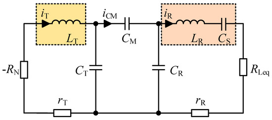
Figure 4.
An equivalent circuit model of the proposed GPT-based CPT system.
Defining as the inductance ratio between the Tx and Rx sides, the load side capacitance can be expressed as
Then, (5) can be rewritten as
where and are the quality factors of the Rx and Tx sides. is the ratio of the operating angular frequency to the resonant angular frequency.
From (7), the fundamental characteristics of the system can be obtained as
Separating the real and imaginary parts in the characteristic equation, (8) can be written as
According to (9), the operating angular frequency can be derived as
where , and is the critical coupling coefficient, which can be expressed as
As can be observed from (10) and (11), the operating range of the proposed system can be divided into the exact PT-symmetric region with frequency splitting and the broken PT-symmetric region with frequency unity . Therefore, according to the range of the coupling coefficient k, the transfer characteristics of the system can be discussed as follows.
2.2.1. In the Exact PT-Symmetric Region
When the system coupling coefficient k between the Tx side and Rx side exceeds the critical coupling coefficient kC, the system works in the exact PT-symmetric region with frequency splitting (i.e., strong coupling region). In this case, the GPT-based CPT system can automatically select the high-frequency branch f1 or low-frequency branch f2 to operate. The operating frequency is
According to (9), when the system operates in the exact PT-symmetric region,
Then, the negative resistance can be expressed as
Submitting (13) into (5), the current ratio of the Rx and Tx sides can be described as
According to (15) and Kirchhoff’s Current Law, the current ratio of the load and Rx side can be obtained as
Then, according to (15) and (16), the current ratio of the load and Tx side is
Since and , the relationship between load voltage and input voltage can be expressed as
Therefore, the output power and transfer efficiency can be expressed as follows:
where .
By employing the aforementioned equation, it is evidently perceived that the current ratio, voltage ratio, output power, and transfer efficiency in the exact PT-symmetric region are independent of the coupling coefficient k.
Consequently, the maintenance of constant output characteristics independent of the coupling coefficient can be achieved even if the Rx side moves in the strong coupling region.
2.2.2. In the Broken PT-Symmetric Region
When the system coupling coefficient k between the Tx side and Rx side is less than the critical coupling coefficient kC, the system works in the broken PT-symmetric region with frequency unity (i.e., weak coupling region). The GPT-based CPT system operates at the resonant frequency f3, which can be derived as
When the system operates in the weak coupling region, the negative resistance can be deduced as
Based on (5), the current ratio between the load and Tx side can be presented as
According to (22) and (23), the voltage ratio between the load and Tx side can be expressed as
Subsequently, the output power and transfer efficiency can be represented as follows:
From (25) and (26), it can be seen that in the weak coupling region, the output power and transfer efficiency are dependent on the coupling coefficient k, and the system cannot achieve constant output characteristics.
As a result, in practical applications, it is advisable to avoid the occurrence of the system coupling coefficient k between the Tx side and Rx side being less than the critical coupling coefficient kc to obtain stable output characteristics.
2.3. Parameter Selection and Comparison
Based on (11) and (20), the critical coupling coefficient kC and transfer efficiency η are related to the capacitance distribution ratio α and inductance coefficient ratio γ. The transfer characteristic curves are drawn in Figure 5, and the circuit parameters are listed in Table 1. It can be seen that kC and η increase with the increase in α and decrease with the increase in γ, but the output power P decreases with the increase in α and γ.
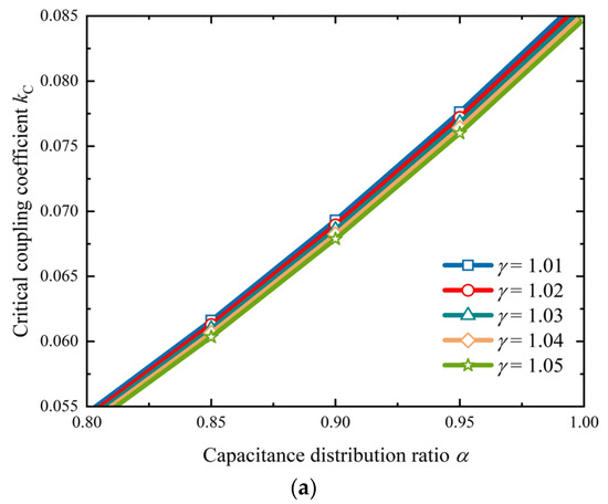

Figure 5.
Transfer characteristics. (a) Critical coupling coefficient. (b) Output power. (c) Transfer efficiency.

Table 1.
The parameters of the experimental prototype.
Figure 6 depicts the relationship between the system’s operating frequency and coupling coefficient, from which the effects of different capacitance distribution ratios on the system operating frequency and critical coupling coefficient can be compared more intuitively.
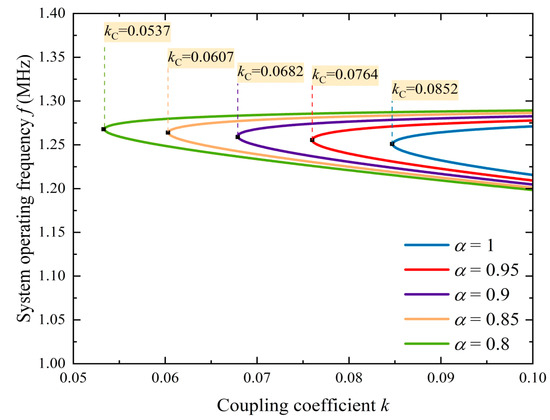
Figure 6.
Operating frequency versus coupling coefficient under γ = 1.05.
From the above analysis, it can be seen that the method of PS resonant capacitors on the load side can reduce the critical coupling coefficient and improve the output power of the system, but this will sacrifice transfer efficiency. Similarly, the inductance coefficient ratio has a similar impact on the system’s transfer characteristics. Therefore, through a comprehensive analysis of Figure 5 and Figure 6, it can be found that the selection of α = 0.95 and γ = 1.05 can extend the PT-symmetric region while maintaining 90% transfer efficiency.
The transfer characteristics of the original SS compensation topology and proposed S-PS compensation topology are compared in Figure 7; it can be seen that under the same circuit parameters, the S-PS structure can reduce the critical coupling coefficient from 0.0873 of the original SS structure to 0.0764.
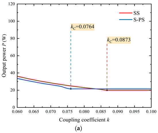
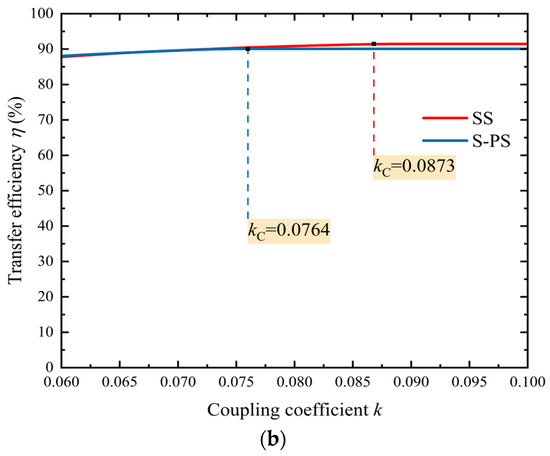
Figure 7.
Comparison of transfer characteristics between SS and S-PS compensation topologies. (a) Output power. (b) Transfer efficiency.
3. Experimental Verification
The experimental prototype is shown in Figure 8, and the circuit parameters are listed in Table 1. The transmitter and receiver are constructed from cylindrical coppers with a height of 150 mm and diameters of 95 and 85 mm, respectively.
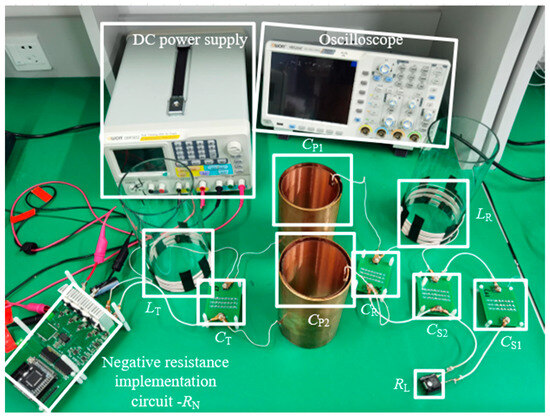
Figure 8.
Experimental prototype.
The relationship between the coupling coefficient and the insertion depth of the capacitive coupler was measured by a precise impedance analyzer. Here, we add a plastic gasket with a height of 10 mm and a diameter of 85 mm to the bottom of the internal barrel metal plate and measure the depth of the plate insertion by adding the number of gaskets. The measured data are shown in Figure 9. The PT-symmetric region of the original PT-based CPT system with SS topology is the blue region. The system widening region proposed in this paper is the light red region, and the PT-symmetric region of the proposed GPT-based CPT system is the light red region plus the blue region.
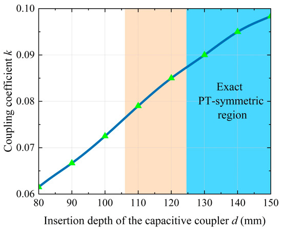
Figure 9.
The relationship between the coupling coefficient and the insertion depth of the capacitive coupler.
Figure 10 shows the experimental waveforms of voltages uT and uL and currents iT and iL when the insertion depth is 150 mm. From Figure 10a, it can be found that the phase difference between the input voltage uT and transmitter current iT is 0 in the reference direction, which means that negative resistance is realized, and the experimental measured data agree well with the theoretical calculated values.
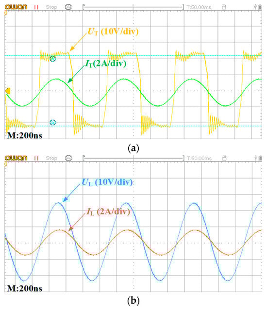
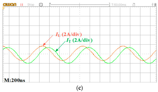
Figure 10.
Experimental waveforms. (a) Input voltage and current. (b) Load voltage and current. (c) Load current and Tx current.
More experimental measured data of output power and transfer efficiency are given in Figure 11; it can be seen that in the exact PT-symmetric region, output power stabilizes around 21.5 W, while the transfer efficiency is 90%.
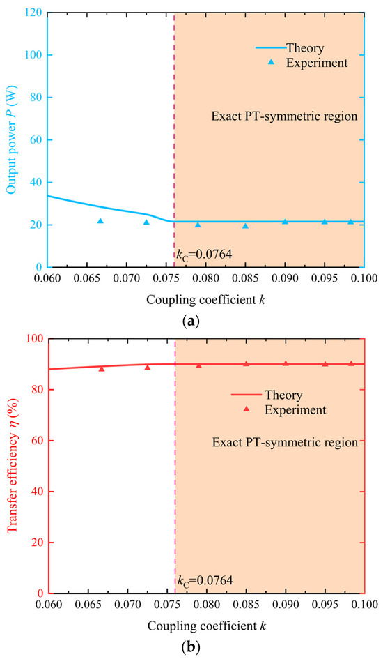
Figure 11.
The transfer character of the system. (a) Output power. (b) Transfer efficiency.
In addition, the critical coupling coefficient is kC = 0.0764, which is significantly reduced compared to the kC = 0.0873 of the original SS topology. Therefore, the experimental results are basically consistent with the theoretical analysis.
4. Conclusions
In this paper, a novel GPT-based CPT system with S-PS compensation topology is proposed, which extends the insertion depth while maintaining constant output characteristics. The theoretical and experimental results show that the critical coupling coefficient of the proposed system decreases from 0.0873 to 0.0764, the insertion depth is extended by approximately 18 mm, and the exact PT-symmetric region is expanded by 169.23% compared with the original PT-based CPT system. Moreover, the proposed system can maintain stable current and voltage ratios, as well as a constant output power of 21.5 W and a constant transfer efficiency of 90%. In a word, the proposed system effectively enhances the system’s insertion depth without increasing the control complexity, thus expanding the practicability of the PT-based CPT system.
Author Contributions
Conceptualization, X.S. and R.O.; methodology, X.S. and R.O.; software, G.W. and R.O.; validation, R.O. and G.W.; formal analysis, X.S.; investigation, X.S.; resources, X.S.; data curation, R.O.; writing—original draft preparation, X.S. and R.O.; writing—review and editing, X.S. and R.O.; visualization, X.S.; supervision, X.S., J.Y. and Y.J.; project administration, X.S. and Y.J.; funding acquisition, Y.J. and X.S. All authors have read and agreed to the published version of the manuscript.
Funding
This work was supported by National Natural Science Foundation of China under Grants 52207193 and 62201153 and the Natural Science Foundation of Fujian Province, China, under Grant 2023J01264.
Data Availability Statement
Data are contained within this article.
Conflicts of Interest
The authors declare no conflicts of interest.
References
- Zhang, Z.; Pang, H.; Georgiadis, A.; Cecati, C. Wireless Power Transfer-An Overview. IEEE Trans. Ind. Electron. 2019, 66, 1044–1058. [Google Scholar] [CrossRef]
- Kracek, J.; Svanda, M. Analysis of Capacitive Wireless Power Transfer. IEEE Access 2019, 7, 26678–26683. [Google Scholar] [CrossRef]
- Sagar, A.; Kashyap, A.; Nasab, M.A.; Padmanaban, S.; Bertoluzzo, M.; Kumar, A.; Blaabjerg, F. A Comprehensive Review of the Recent Development of Wireless Power Transfer Technologies for Electric Vehicle Charging Systems. IEEE Access 2023, 11, 83703–83751. [Google Scholar] [CrossRef]
- Lu, F.; Zhang, H.; Mi, C. A Two-Plate Capacitive Wireless Power Transfer System for Electric Vehicle Charging Applications. IEEE Trans. Power Electron. 2018, 33, 964–969. [Google Scholar] [CrossRef]
- Yang, L.; Zhang, Y.; Li, X.; Feng, B.; Chen, X.; Huang, J.; Yang, T.; Zhu, D.; Zhang, A.; Tong, X. Comparison Survey of Effects of Hull on AUVs for Underwater Capacitive Wireless Power Transfer System and Underwater Inductive Wireless Power Transfer System. IEEE Access 2022, 10, 125401–125410. [Google Scholar] [CrossRef]
- Hossain, A.N.M.S.; Mohseni, P.; Lavasani, H.M. Design and Optimization of Capacitive Links for Wireless Power Transfer to Biomedical Implants. IEEE Trans. Biomed. Circuits Syst. 2022, 16, 1299–1312. [Google Scholar] [CrossRef] [PubMed]
- Yang, L.; Ju, M.; Zhang, B. Bidirectional Undersea Capacitive Wireless Power Transfer System. IEEE Access 2019, 7, 121046–121054. [Google Scholar] [CrossRef]
- Lu, F.; Zhang, H.; Hofmann, H.; Mi, C. A Double-Sided LCLC-Compensated Capacitive Power Transfer System for Electric Vehicle Charging. IEEE Trans. Power Electron. 2015, 30, 6011–6014. [Google Scholar] [CrossRef]
- Tamura, M.; Naka, Y.; Murai, K.; Nakata, T. Design of a Capacitive Wireless Power Transfer System for Operation in Fresh Water. IEEE Trans. Microw. Theory 2018, 66, 5873–5884. [Google Scholar] [CrossRef]
- Qing, X.; Su, Y.; Hu, A.P.; Dai, X.; Liu, Z. Dual-Loop Control Method for CPT System Under Coupling Misalignments and Load Variations. IEEE J. Emerg. Sel. Top. Power Electron. 2021, 10, 4902–4912. [Google Scholar] [CrossRef]
- Cai, C.; Liu, X.; Wu, S.; Chen, X.; Chai, W.; Yang, S. A Misalignment Tolerance and Lightweight Wireless Charging System via Reconfigurable Capacitive Coupling for Unmanned Aerial Vehicle Applications. IEEE Trans. Power Electron. 2022, 38, 22–26. [Google Scholar] [CrossRef]
- Jiang, C.; Wei, B.; Xu, C.; Wu, X.; He, H. Efficiency Improvement Under Coupler Misalignment for Dual-Transmitter and Single-Receiver Capacitive Power Transfer System. IEEE Trans. Power Electron. 2023, 38, 14872–14883. [Google Scholar] [CrossRef]
- Jiang, Y.; Zhou, Y.; Zhang, B.; Chen, W.; Chen, Q.; Shu, X. A Robust Capacitive Power Transfer System via Fractional-Order Autonomous Circuit. IEEE J. Emerg. Sel. Top. Power Electron. 2024, 12, 3258–3267. [Google Scholar] [CrossRef]
- Liu, Z.; Hu, H.; Su, Y.G.; Sun, Y.; Chen, F.; Deng, P. A Double-Receiver Compact SCC-WPT System With CV/CC Output for Mobile Devices Charging/Supply. IEEE Trans. Power Electron. 2023, 38, 9230–9245. [Google Scholar] [CrossRef]
- Wei, X.; Shen, X.; Jiang, J.; Luo, S.; Zhu, Y.; Ma, H. An Improved Design Method Based on a Multiplate Coupler Structure for Capacitive Power Transfer With Wide Ranges of Misalignment and Loads. IEEE J. Emerg. Sel. Top. Power Electron. 2024, 12, 5311–5322. [Google Scholar] [CrossRef]
- van Ieperen, A.; Derammelaere, S.; Minnaert, B. Coupling-Independent Capacitive Wireless Power Transfer With One Transmitter and Multiple Receivers Using Frequency Bifurcation. IEEE Open J. Power Electron. 2024, 5, 891–901. [Google Scholar] [CrossRef]
- Lian, J.; Qu, X. An LCLC-LC-Compensated Capacitive Power Transferred Battery Charger With Near-Unity Power Factor and Configurable Charging Profile. IEEE Trans. Ind. Appl. 2021, 58, 1053–1060. [Google Scholar] [CrossRef]
- Shinde, K.; Koizumi, H. Capacitive Power Transfer System Using a Load-Independent Class E Zero Voltage Switching Parallel Resonant Inverter and a Class D Voltage-Driven Rectifier. IEEE Trans. Circuits Syst. II Express Briefs 2024, 71, 4366–4370. [Google Scholar] [CrossRef]
- Zhou, W.; Chen, Z.; Zhang, Q.; Li, Z.; Huang, L.; Mai, R.; He, Z. Design and Analysis of CPT System With Wide-Range ZVS and Constant Current Charging Operation Using 6.78 MHz Class-E Power Amplifier. IEEE J. Emerg. Sel. Top. Power Electron. 2024, 12, 3211–3225. [Google Scholar] [CrossRef]
- Assawaworrarit, S.; Yu, X.; Fan, S. Robust wireless power transfer using a nonlinear parity–time-symmetric circuit. Nature 2017, 546, 387–390. [Google Scholar] [CrossRef]
- Gu, W.; Qiu, D.; Shu, X.; Zhang, B.; Xiao, W.; Chen, Y. A Constant Output Capacitive Wireless Power Transfer System Based on Parity-Time Symmetric. IEEE Trans. Circuits Syst. II Express Briefs 2023, 70, 2585–2589. [Google Scholar] [CrossRef]
- Assawaworrarit, S.; Fan, S. Robust and efficient wireless power transfer using a switch-mode implementation of a nonlinear parity time symmetric circuit. Nature Electron. 2020, 3, 273–279. [Google Scholar] [CrossRef]
- Chen, P.Y.; Sakhdari, M.; Hajizadegan, M.; Cui, Q.; Cheng, M.M.C.; El-Ganainy, R.; Alù, A. Generalized parity-time symmetry condition for enhanced sensor telemetry. Nature Electron. 2018, 1, 297–304. [Google Scholar] [CrossRef]
- Zhang, H.; Lu, F.; Hofmann, H.; Liu, W.; Mi, C.C. A Four-Plate Compact Capacitive Coupler Design and LCL-Compensated Topology for Capacitive Power Transfer in Electric Vehicle Charging Application. IEEE Trans. Power Electron. 2016, 31, 8541–8551. [Google Scholar]
- Wu, X.; Su, Y.; Hu, A.P.; Qing, X.; Hou, X. Multiobjective Parameter Optimization of a Four-Plate Capacitive Power Transfer System. IEEE J. Emerg. Sel. Top. Power Electron. 2020, 9, 2328–2342. [Google Scholar] [CrossRef]
Disclaimer/Publisher’s Note: The statements, opinions and data contained in all publications are solely those of the individual author(s) and contributor(s) and not of MDPI and/or the editor(s). MDPI and/or the editor(s) disclaim responsibility for any injury to people or property resulting from any ideas, methods, instructions or products referred to in the content. |
© 2024 by the authors. Licensee MDPI, Basel, Switzerland. This article is an open access article distributed under the terms and conditions of the Creative Commons Attribution (CC BY) license (https://creativecommons.org/licenses/by/4.0/).