
A Receiver Position Estimation Method Based on LSTM for Multi-Transmitter Single-Receiver Wireless Power Transfer Systems


Abstract
1. Introduction
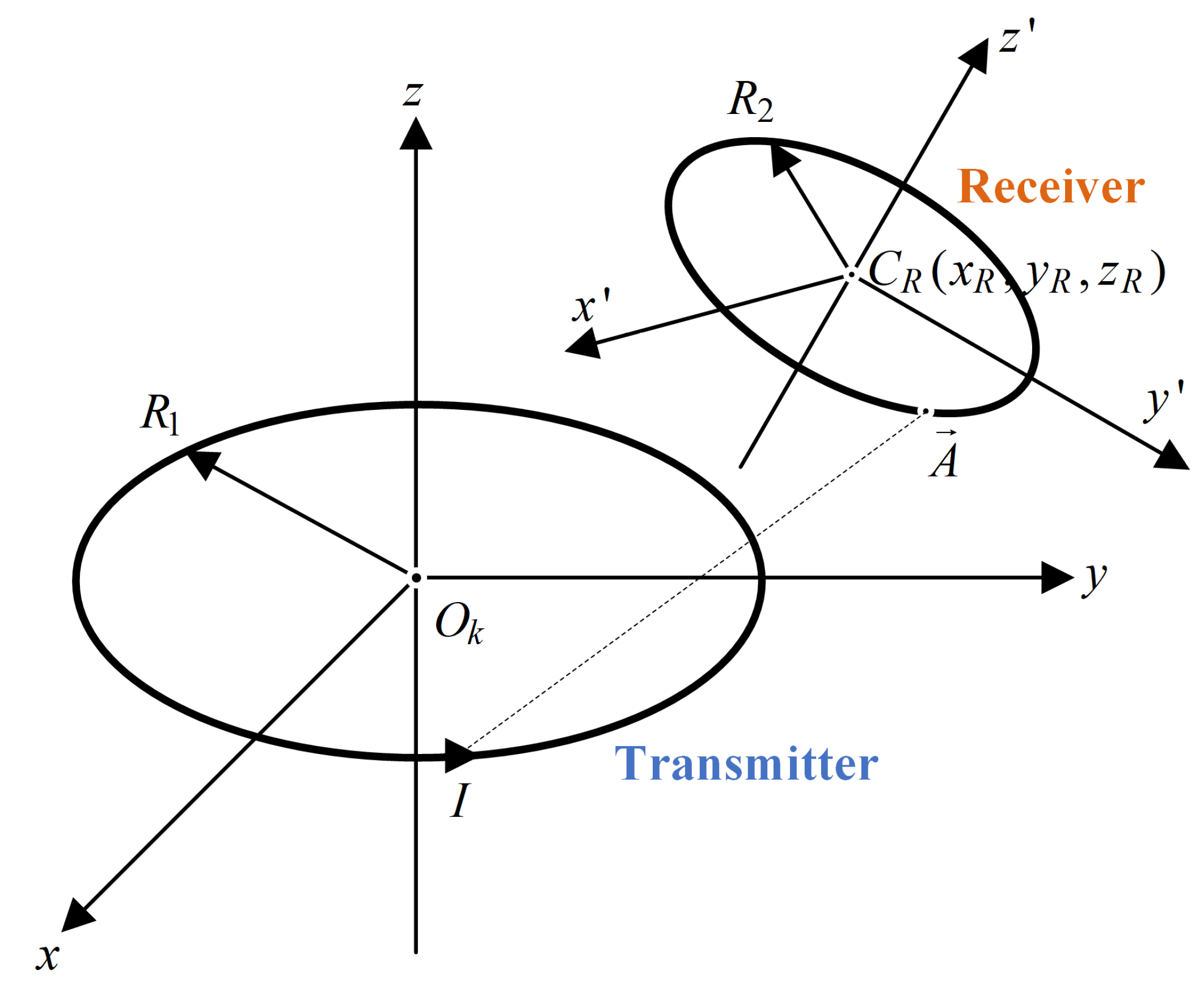
2. Analysis of the MTSR-WPT System
3. Position Estimation Method Based on LSTM
3.1. Standard LSTM Model
3.2. Position Estimation Method
4. Experimental Verification
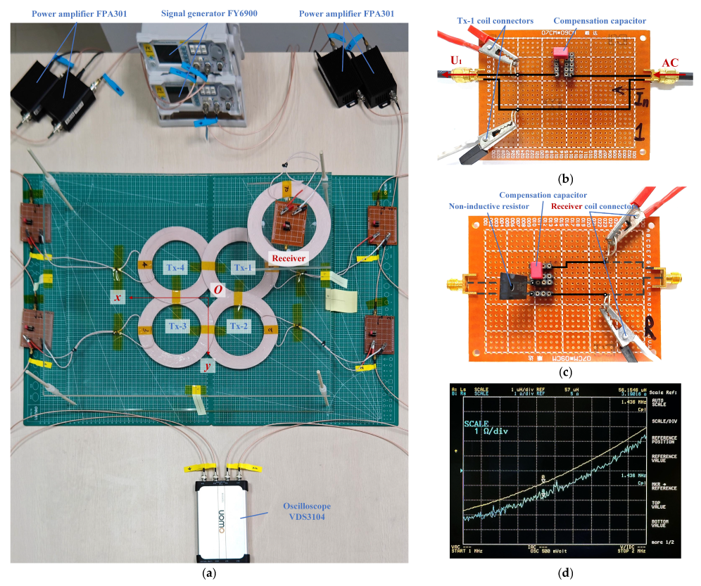
4.1. Implementation and Measurement of the MTSR-WPT System
- (1)
- High-frequency voltage source
- (2)
- Circuit boards of the transmitter and receiver
- (3)
- Measurement equipment

| Parameter Type | Parameter Value |
|---|---|
| Coil inductances (μH) //// | 56.2/56.0/55.9/56.1/56.3 |
| Capacitances (pF) //// | 220.1/216.5/219.7/226.2/224.0 |
| Resistances (Ω) ///// | 3.6/3.5/3.4/3.4/3.6/50 |
| Height of the receiver plane (mm) | 50 |
| Frequencies (MHz) / | 1.436/250 |
- (4)
- Coils

4.2. Verification of the Proposed LSTM-Based Model
- (1)
- Data collection
- (2)
- Construction and Training of the Estimation Model

| Option | Setting |
|---|---|
| Input Shape | (174, 4) |
| LSTM Units | 20 |
| Initial Leaning Rate | 0.001 |
| Optimizer | Adaptive Moment Estimation (Adam) |
| Loss | Mean Absolute Error (MAE) |
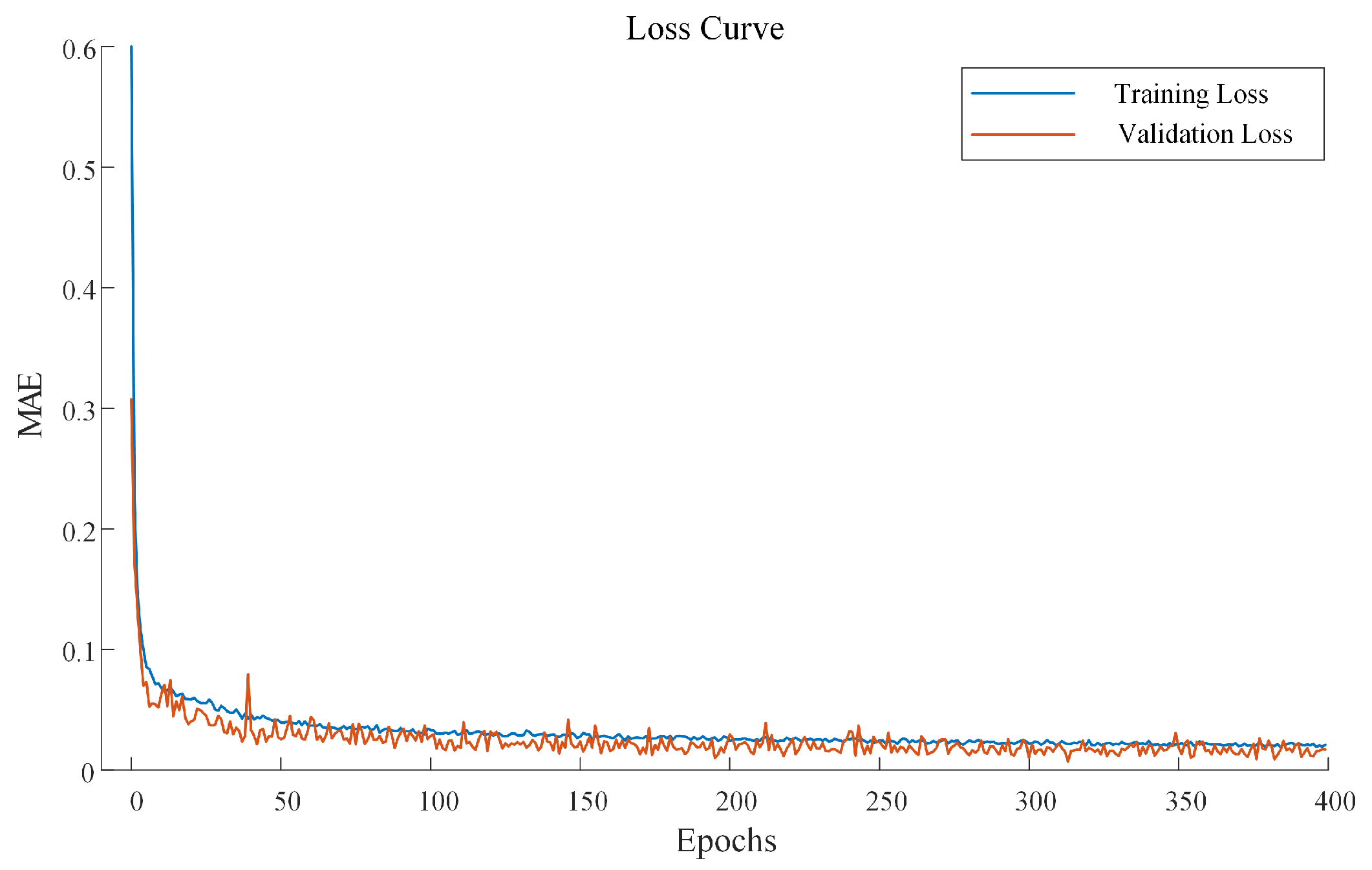
- (3)
- Training Result
- (1)
- For the MTSR-WPT system, the position of the receiver coil can be estimated through a trained neural network model, simplifying the internal mechanism analysis and complex formula derivation of the system.
- (2)
- Through the proposed method, the position of the receiver coil can be estimated solely based on the voltage data of the transmitter coil. In this way, there is no need to add voltage measurement and communication units in the receiver circuit.
- (3)
- When the receiver moves within a range of 160 mm × 160 mm, the average error between the estimated receiver coil position using the proposed method and the actual receiver coil position is less than 2.40 mm.
5. Conclusions
Author Contributions
Funding
Data Availability Statement
Conflicts of Interest
References
- Zhang, Z.; Pang, H.; Georgiadis, A.; Cecati, C. Wireless Power Transfer—An Overview. IEEE Trans. Ind. Electron. 2019, 66, 1044–1058. [Google Scholar] [CrossRef]
- Wang, Y.; Sun, Z.; Guan, Y.; Xu, D. Overview of Megahertz Wireless Power Transfer. Proc. IEEE 2023, 111, 528–554. [Google Scholar] [CrossRef]
- Jeong, S.; Kim, T.; Lee, S.; Sim, B.; Park, H.; Son, K.; Son, K.; Kim, S.; Shin, T.; Kim, Y.; et al. Analysis of Repetitive Bending on Flexible Wireless Power Transfer (WPT) PCB Coils for Flexible Wearable Devices. IEEE Trans. Compon. Packag. Manuf. Technol. 2022, 12, 1748–1756. [Google Scholar] [CrossRef]
- Wagih, M.; Komolafe, A.; Ullah, I.; Weddell, A.S.; Beeby, S. A Wearable All-Printed Textile-Based 6.78 MHz 15 W-Output Wireless Power Transfer System and Its Screen-Printed Joule Heater Application. IEEE Trans. Ind. Electron. 2024, 71, 3741–3750. [Google Scholar] [CrossRef]
- Jeong, S.; Song, J.; Lee, S.; Hong, S.; Sim, B.; Kim, H.; Kim, S.; Kim, J. Design, Simulation and Measurement of Flexible PCB Coils for Wearable Device Wireless Power Transfer. In Proceedings of the 2018 IEEE Wireless Power Transfer Conference (WPTC), Montreal, QC, Canada, 3–7 June 2018; pp. 1–4. [Google Scholar] [CrossRef]
- Chu, Y.; Chang-Chien, L.; Artan, N.S.; Czarkowski, D.; Chang, C.; Zou, J.; Chao, H.J. On-Chip AC–DC Multiple-Power-Supplies Module for Transcutaneously Powered Wearable Medical Devices. IEEE Trans. Ind. Appl. 2018, 54, 1724–1736. [Google Scholar] [CrossRef]
- Campi, T.; Cruciani, S.; Maradei, F.; Montalto, A.; Musumeci, F.; Feliziani, M. Centralized High Power Supply System for Implanted Medical Devices Using Wireless Power Transfer Technology. IEEE Trans. Med. Robot. Bionics 2021, 3, 992–1001. [Google Scholar] [CrossRef]
- Wang, J.; Lim, E.G.; Leach, M.P.; Wang, Z.; Pei, R.; Jiang, Z.; Huang, Y. A 403 MHz Wireless Power Transfer System With Tuned Split-Ring Loops for Implantable Medical Devices. IEEE Trans. Antennas Propag. 2022, 70, 1355–1366. [Google Scholar] [CrossRef]
- Shin, J.; Shin, S.; Kim, Y.; Ahn, S.; Lee, S.; Jung, G.; Jeon, S.; Cho, D. Design and Implementation of Shaped Magnetic-Resonance-Based Wireless Power Transfer System for Roadway-Powered Moving Electric Vehicles. IEEE Trans. Ind. Electron. 2014, 61, 1179–1192. [Google Scholar] [CrossRef]
- Chu, S.Y.; Cui, X.; Zan, X.; Avestruz, A. Transfer-Power Measurement Using a Non-Contact Method for Fair and Accurate Metering of Wireless Power Transfer in Electric Vehicles. IEEE Trans. Power Electron. 2022, 37, 1244–1271. [Google Scholar] [CrossRef]
- Xu, F.; Wei, S.; Yuan, D.; Li, J. Review on Key Technologies and Development of Magnetic Coupling Resonant-Dynamic Wireless Power Transfer for Unmanned Ground Vehicles. Electronics 2023, 12, 1506. [Google Scholar] [CrossRef]
- Xie, L.; Cao, X.; Xu, J.; Zhang, R. UAV-Enabled Wireless Power Transfer: A Tutorial Overview. IEEE Trans. Green Commun. Netw. 2021, 5, 2042–2064. [Google Scholar] [CrossRef]
- Chittoor, P.K.; Bharatiraja, C. Wireless-Sensor Communication Based Wireless-Charging Coil Positioning System for UAVs With Maximum Power Point Tracking. IEEE Sens. J. 2022, 22, 8175–8182. [Google Scholar] [CrossRef]
- Wu, S.; Cai, C.; Liu, X.; Chai, W.; Yang, S. Compact and Free-Positioning Omnidirectional Wireless Power Transfer System for Unmanned Aerial Vehicle Charging Applications. IEEE Trans. Power Electron. 2022, 37, 8790–8794. [Google Scholar] [CrossRef]
- Li, Y.; Ni, X.; Liu, J.; Wang, R.; Ma, J.; Zhai, Y.; Huang, Y. Design and Optimization of Coupling Coils for Bidirectional Wireless Charging System of Unmanned Aerial Vehicle. Electronics 2020, 9, 1964. [Google Scholar] [CrossRef]
- Wang, M.; Song, G.; Yin, R.; Shi, Y. Design and Analysis of an Anti-Misalignment Wireless Power Transfer System. IEEE Microw. Wirel. Technol. Lett. 2023, 33, 228–231. [Google Scholar] [CrossRef]
- Darvish, P.; Hossain, A.; Mekhilef, S.; Tey, K.S.; Mubin, M.B.; Yin, J.; Akhtar, M.M.; Mustafa, A.; Khalid, H.; Imtiaz, T.; et al. Dual Receiver-Based Naturally Decoupled Coil Structure with Improved Rotational Misalignment Tolerance for WPT systems. IEEE Trans. Transp. Electrif. 2023, 10, 5412–5423. [Google Scholar] [CrossRef]
- Pan, W.; Liu, C.; Tang, H.; Zhuang, Y.; Zhang, Y. An Interoperable Electric Vehicle Wireless Charging System Based on Mutually Spliced Double-D Coil. IEEE Trans. Power Electron. 2024, 39, 3864–3872. [Google Scholar] [CrossRef]
- Lin, J.; Mao, X.; Su, T.; Qi, W.; Wang, Y.; Zhang, Y. Magnetic Coupler Parameters Optimization for Electric Vehicle Charging System with DQD Coil Structure. IEEE J. Emerg. Sel. Top. Power Electron. 2024, 1. [Google Scholar] [CrossRef]
- Kang, N.; Shao, Y.; Liu, M.; Ma, C. Analysis and Implementation of 3D Magnetic Field Shaping via a 2D Planar Transmitting Coil Array. IEEE Trans. Power Electron. 2022, 37, 1172–1184. [Google Scholar] [CrossRef]
- Song, J.; An, H.; Li, Y.; Zhang, C.; Liu, G. Modeling and Experimental Analysis of Three-Dimensional Crossed Coil Structure for Misaligned Wireless Power Transfer System. Prog. Electromagn. Res. C 2020, 106, 89–103. [Google Scholar] [CrossRef]
- Jung, K.; Park, J.; Son, S.; Ahn, S. Position Prediction of Wireless Charging Electric Vehicle for Auto Parking using Extreme Gradient Boost Algorithm. In Proceedings of the 2020 IEEE Wireless Power Transfer Conference (WPTC), Seoul, Republic of Korea, 15–19 November 2020; pp. 439–442. [Google Scholar] [CrossRef]
- Gao, S.; Wang, Q.; Li, G.; Qian, Z.; Ye, Q.; Zhang, Q.; Li, Z. Novel Design of Multi-DOF Motor Position Estimation Based on Wireless Power Transmission Modeling. IEEE Trans. Ind. Electron. 2024, 71, 2853–2863. [Google Scholar] [CrossRef]
- Li, D.; Wu, X.; Gao, W.; Gao, J. Planar Position Recognition of Receiver Coil Based on Multi- Transmitter Array Wireless Power Transfer System. Preprints 2023, 090930. [Google Scholar] [CrossRef]
- Xu, J.; Tan, P.; Shen, H.; Zhang, H.; Pang, L.; Deng, Y. Angle Prediction for Field Orientation Based on Back Propagation Neural Network of Wireless Power Transfer System. In Proceedings of the 2020 IEEE 9th International Power Electronics and Motion Control Conference (IPEMC2020-ECCE Asia), Nanjing, China, 29 November–2 December 2020; pp. 1947–1951. [Google Scholar] [CrossRef]
- Gong, Y.; Otomo, Y.; Igarashi, H. Neural Network for Both Metal Object Detection and Coil Misalignment Prediction in Wireless Power Transfer. IEEE Trans. Magn. 2022, 58, 7201004. [Google Scholar] [CrossRef]
- Shen, H.; Tan, P.; Song, B.; Gao, X.; Zhang, B. Receiver Position Estimation Method for Multitransmitter WPT System Based on Machine Learning. IEEE Trans. Ind. Appl. 2022, 58, 1231–1241. [Google Scholar] [CrossRef]
- Babic, S.; Sirois, F.; Akyel, C.; Girardi, C. Mutual Inductance Calculation Between Circular Filaments Arbitrarily Positioned in Space: Alternative to Grover’s Formula. IEEE Trans. Magn. 2010, 46, 3591–3600. [Google Scholar] [CrossRef]


| Input Layer | Epochs | Average Error (mm) |
|---|---|---|
| LSTM | 20 | 13.15 |
| 200 | 6.62 | |
| 400 | 2.40 | |
| RNN | 400 | 19.33 |
Disclaimer/Publisher’s Note: The statements, opinions and data contained in all publications are solely those of the individual author(s) and contributor(s) and not of MDPI and/or the editor(s). MDPI and/or the editor(s) disclaim responsibility for any injury to people or property resulting from any ideas, methods, instructions or products referred to in the content. |
© 2024 by the authors. Licensee MDPI, Basel, Switzerland. This article is an open access article distributed under the terms and conditions of the Creative Commons Attribution (CC BY) license (https://creativecommons.org/licenses/by/4.0/).
Share and Cite
Dai, Z.; Yang, Y.; Luo, Y.; Chen, S.; Lin, Z. A Receiver Position Estimation Method Based on LSTM for Multi-Transmitter Single-Receiver Wireless Power Transfer Systems. Electronics 2024, 13, 4670. https://doi.org/10.3390/electronics13234670
Dai Z, Yang Y, Luo Y, Chen S, Lin Z. A Receiver Position Estimation Method Based on LSTM for Multi-Transmitter Single-Receiver Wireless Power Transfer Systems. Electronics. 2024; 13(23):4670. https://doi.org/10.3390/electronics13234670
Chicago/Turabian StyleDai, Zhuoyue, Yongmin Yang, Yanting Luo, Suiyu Chen, and Zhilong Lin. 2024. "A Receiver Position Estimation Method Based on LSTM for Multi-Transmitter Single-Receiver Wireless Power Transfer Systems" Electronics 13, no. 23: 4670. https://doi.org/10.3390/electronics13234670
APA StyleDai, Z., Yang, Y., Luo, Y., Chen, S., & Lin, Z. (2024). A Receiver Position Estimation Method Based on LSTM for Multi-Transmitter Single-Receiver Wireless Power Transfer Systems. Electronics, 13(23), 4670. https://doi.org/10.3390/electronics13234670