Abstract
Uninterruptible Power Supplies (UPSs) protect electronic equipment by delivering consistent power. Among the core components of a UPS is the inverter, which converts stored DC energy from batteries into AC power. This work focuses on a cascaded multilevel inverter topology for its ability to reduce voltage Total Harmonic Distortion (THD), which is essential for maintaining UPS efficiency and power quality. Using an ANFIS (Adaptive Neuro-Fuzzy Inference System) model, enhanced with the Particle Swarm Optimization (PSO) algorithm, the switching angles were optimized to minimize THD. This work focused on an online UPS with a seven-level inverter structure powered by three LifePo4 S17 batteries, with critical load levels (100%, 95%, 50%, 15%, and 5%) represented in 35 experimental cases. The experimental design allowed the ANFIS-PSO model to adapt to varying voltages, achieving robust THD reduction. The results demonstrated that this combination of ANFIS and PSO provided effective angle optimization, with a low standard deviation of 0.06 between the training and simulated %THD, highlighting the process’s accuracy. The analysis showed that, in most cases, the simulated THD values closely aligned with, or even improved upon, the calculated values, with discrepancies not exceeding 0.2%. These findings support the ANFIS-PSO model’s potential in enhancing power electronics applications, particularly in critical sectors like renewable energy and power transmission, where THD minimization is crucial.
1. Introduction
UPSs have reached a level of maturity that allows them to provide clean, uninterruptible power to sensitive loads, even under varying mains conditions. UPSs generally deliver a regulated sinusoidal output voltage with low THD and a high input power factor, regardless of changes in mains voltage, protecting critical equipment from damage and preventing data loss or unexpected failures [1,2]. This is crucial for applications that cannot tolerate interruptions or variations in power quality, such as communication systems, data centers, and medical equipment. In industrial or mission-critical environments, UPSs allow for a smooth transition to emergency generators or other backup sources without interrupting operations, which is crucial to avoid downtime in systems that rely on continuous operation.
UPS systems are classified into the following three main categories: offline UPSs, line-interactive UPSs, and online UPSs. Each configuration has specific characteristics that make it suitable for different applications [1,3]. Online UPSs, which provide continuous and complete protection against fluctuations in the power grid, are best-suited for critical applications, such as data centers, medical systems, and communications, where stable and accurate power quality is critical. While the consequences of poor power quality are not always obvious at first glance, they can have significant hidden costs that impact productivity, equipment life, and overall profitability [4].
Despite their advantages, online UPSs faces certain challenges, such as transient management, high THD levels, and noise, which can negatively impact the quality of the delivered power. To mitigate these problems, multilevel inverters (MLIs), specifically cascaded H-bridge inverters (CHBMLIs), have been positioned as an effective solution due to their ability to reduce THD and improve the harmonic spectrum [1].
However, implementing modulation techniques, such as Pulse Width Modulation (PWM), is a key factor in further optimizing online UPS performance, allowing for more precise control of inverter switches.
Figure 1 illustrates the operation of an online UPS, its main components, and the power flow within the system. This diagram shows how CHBMLIs and modulation techniques are crucial in improving the power supply quality. In power generation, there are growing concerns about improving both the efficiency and the quality of the conversion. CHBMLIs have been noted for their efficiency in medium- and high-power applications and ability to reduce the filters’ size and improve the power supply quality, making them an ideal choice for integration into modern UPSs [5]. However, one of the main challenges remains the management of voltage variations, which can significantly increase THD and affect the quality of the delivered power.
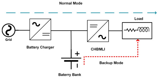
Figure 1.
Operation of an online UPS [1].
Although CHBMLIs have many advantages, MLIs have generally become the most widely used energy transformation technology for many applications [6]. Although MLIs offer significant advantages, their implementation presents complications, and researchers are exploring new strategies to improve their performance [7]. One such strategy is using Artificial Intelligence (AI), which has been highlighted as a powerful tool for optimizing MLI performance.
Although it has multiple definitions due to the vagueness of the term “intelligence”, AI can be described as the science and engineering of machines capable of understanding their environment and making informed decisions [8]. In short, AI seeks to approximate human thinking to efficiently and adaptively solve problems. Within the field of AI, the following three main branches stand out: fuzzy logic, genetic algorithms, and artificial neural networks (ANNs). ANNs attempt to reproduce the brain’s problem-solving process [9,10]. ANNs, like the human brain, require a training process where they are fed with prior knowledge to solve specific problems. Despite their success, ANNs face challenges in interpretability and adaptability in highly variable systems. To address these limitations, ANFIS was developed as a hybrid model combining neural networks’ learning ability with fuzzy logic’s interpretability, offering flexibility and clarity in complex problem-solving scenarios. This combination makes ANFIS particularly suitable for applications that demand precise adjustments and adaptability, such as multilevel inverter optimization.
Both ANNs and ANFIS require training, typically achieved through iterative methods, though recent years have seen a shift toward using metaheuristic methods to improve their convergence and solution quality. Metaheuristic methods are algorithms designed to efficiently explore the search space and identify optimal solutions to complex problems. Unlike classical techniques like Newton–Raphson (NR) or Gradient Descent (GD), metaheuristic algorithms mimic natural or social processes, providing increased flexibility and adaptability to diverse scenarios [11,12].
Although integrating metaheuristic methods into network training has shown potential benefits, their application remains limited. Few studies have demonstrated improvements using these methods in ANFIS training, leaving the field largely unexplored.
While ANFIS networks have found broad applications in various areas, their use in power electronics, particularly for optimizing multilevel inverters, remains limited. Most studies focus on ANFIS for optimizing electrical systems and electric motors, with only a few directly addressing its implementation in inverters and power electronics [13,14].
Table 1 presents a selection of studies where ANFIS networks were applied to multilevel inverters across various applications. This table highlights the limited number of works focused on implementing ANFIS, specifically in inverters, with even fewer addressing their application in UPS systems. The table also summarizes the training methods employed in these studies and the THD results obtained.

Table 1.
ANFIS applied to multilevel inverters.
In Table 1, although ANFIS and metaheuristic optimization techniques have been applied in various areas of power electronics, there is little specific research on their use in UPS systems, as most applications focus on photovoltaic systems. In addition, many studies employ ANFIS for voltage control or other types of controllers, while few focus on effective THD minimization. However, ANFIS often performs better than other methods (such as ANNs or fuzzy logic). In particular, references [15,20,24,25] used ANFIS combined with additional training methods other than gradient descent, the most commonly employed basic method. References [15,20] stand out for employing a combination of ANFIS with PSO, obtaining the best results in THD reduction. This indicates a remarkable efficiency and suggests a promising area for future research. Furthermore, it is important to note that the authors employed different topologies and inverter levels, making it difficult to standardize or directly compare THD improvements. This underscores the need for further studies focusing on these systems, and the present work seeks to fill precisely that gap.
A recent state-of-the-art review article [36] highlighted that, while some papers focus on ANFIS applied to multilevel inverters, few researchers have used metaheuristic methods to train ANFIS networks. A few papers have combined ANFIS with metaheuristic methods, such as PSO, GA (Genetic Algorithm), and ABC (Artificial Bee Colony). Although these studies are relatively few, they have shown promise in the training and optimization process. These combinations represent a novelty in the field and suggest an untapped potential in integrating ANFIS with metaheuristic methods [34,37].
This paper proposes an innovative solution by combining ANFIS with the PSO algorithm to optimize the switching angles in multilevel inverters. Maintaining harmonic distortion within acceptable limits is essential for high-quality power output, as the IEEE 519 standard [38] recommends that the THD should be kept below 8%. However, achieving this threshold without resorting to large and complex filters is challenging in multilevel inverters with voltage variations. This study focuses on minimizing the voltage THD at the inverter output by optimizing the switching angles with ANFIS and PSO to reduce the harmonic content from the outset. By achieving a lower voltage THD at this stage, the filters required in a real-world system can be smaller and less complex, simplifying the design while ensuring compliance with regulatory standards. ANFIS, by combining the capabilities of neural networks and fuzzy logic, provides great flexibility and accuracy in predicting the optimal switching angles.
This approach represents a significant advance in power electronics, enabling UPS systems to operate efficiently and with a low harmonic content, even with fluctuating source voltages. The rest of the manuscript is organized as follows: Section 2 presents the materials and methods used, where the fundamentals of ANFIS and PSO networks are established, along with the key parameters used in PSO optimization. This section also includes the problem formulation, the proposed solution, and the development of the case study, which was defined using a design of experiments. Section 3 presents the results of the ANFIS network training, broken down into training and testing stages, and the simulations performed in MATLAB R2021a for the case study. Section 4 provides a detailed discussion of the findings and their implications for improving the performance of multilevel inverters. Finally, Section 5 presents the study’s conclusions and possible future directions for this line of research.
2. Materials and Methods
2.1. ANFIS and PSO Fundamentals in Multilevel Inverter Optimization
2.1.1. Adaptive Neuro-Fuzzy Inference System
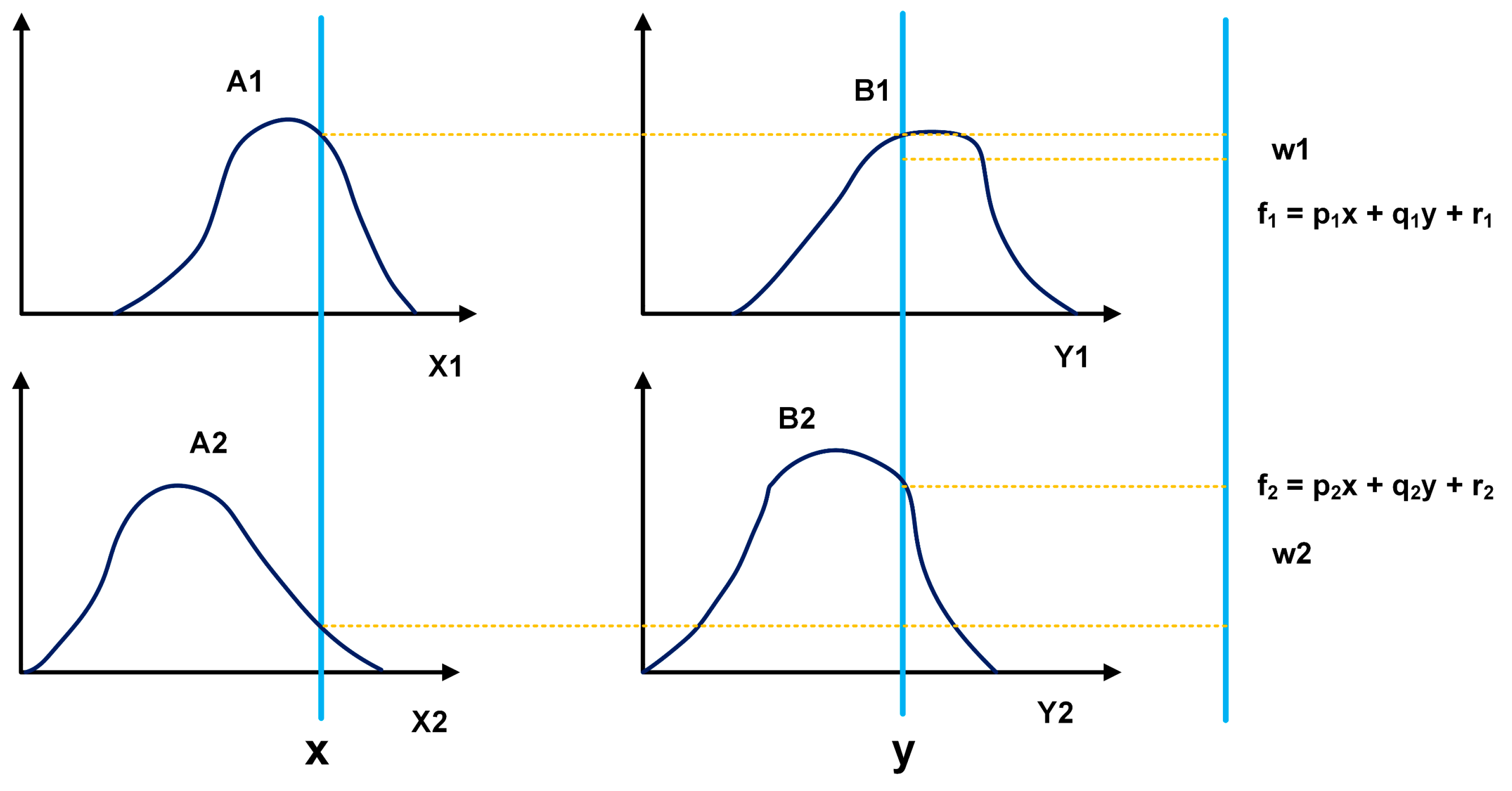
An ANFIS network is a combination of fuzzy logic and neural networks, which use different methods for parameter tuning. R. Jang proposed this network in his thesis on neuro-fuzzy modeling [39]. ANFIS can model complex systems as it incorporates the human reasoning style of fuzzy systems by using fuzzy sets with a linguistic model consisting of a set of fuzzy rules. The main strength of ANFIS models is that they are universal approximators that can request IF-THEN rules [40]. The ANFIS model applies the Takagi–Sugeno fuzzy system to map inputs to the output space, which is expressed as follows for two inputs:
Rule 1: IF “x” is A1 y “y” is B1, THEN f1 = p1x + q1y + r1.
Rule 2: IF “x” is A2 y “y” is B2, THEN f2 = p2x + q2y + r2.
Where p1, p2, q1, q2, r1, and r2 are linear parameters and A1, A2, B1, and B2 are non-linear parameters.
The architecture of an ANFIS model with two inputs is shown in Figure 2.
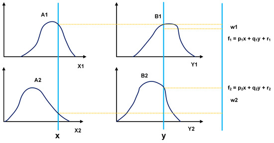
Figure 2.
Evaluation of the fuzzy inference system.
In this context, the final equation of the two-rule fuzzy inference ANFIS system, which combines the results of both rules using their relevance values ( and ), is presented in Equation (1) as follows:
where and represent the normalized weights. This equation describes the final output of the ANFIS system, which is a weighted combination of each rule’s outputs, adaptively integrating the membership values to adjust the model’s accuracy.
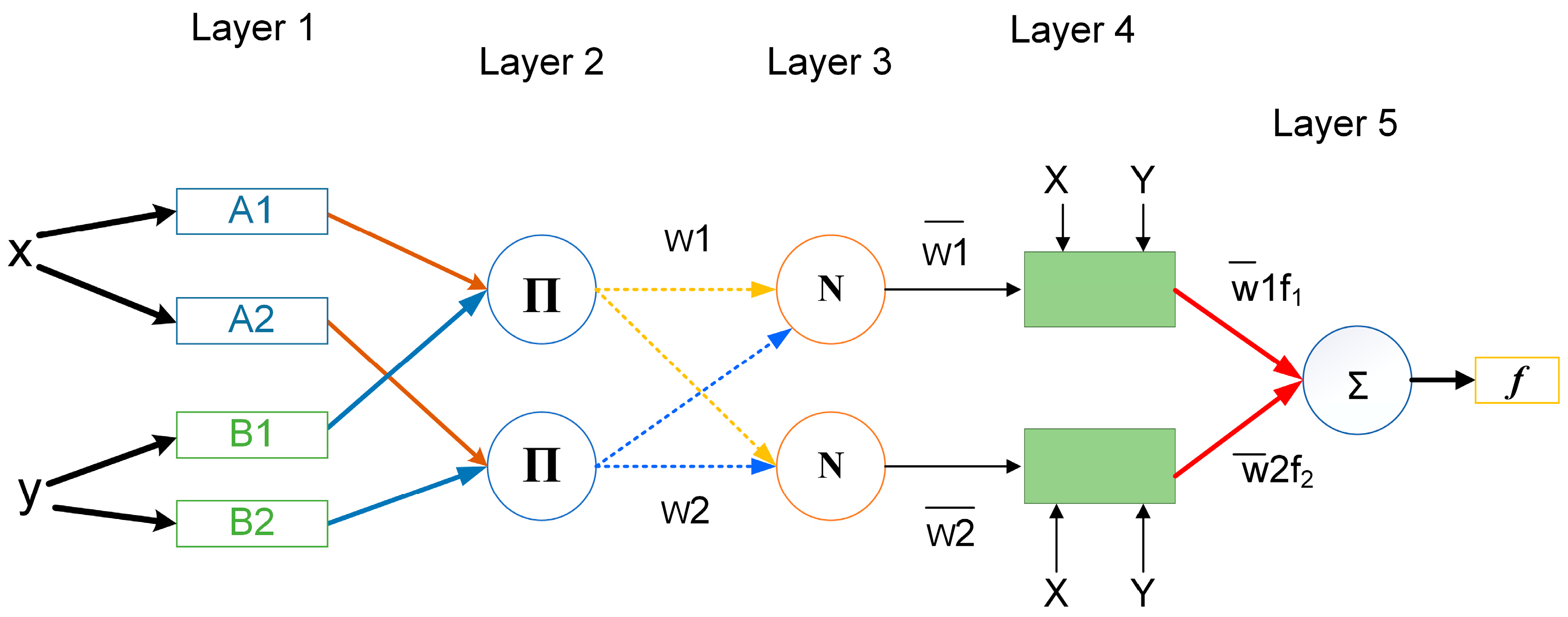
The ANFIS structure, unlike common neural networks, includes five layers, as shown in Figure 3. These layers are explained as follows:

Figure 3.
Structure of an ANFIS network with two inputs and one output.
Layer 1: Fuzzification Layer—This layer transforms input data into linguistic values. The parameters, known as premise parameters, determine the form of the membership function [41,42].
Layer 2: Rules Layer—This layer performs the logical operation “and” by calculating the product between the membership functions obtained in the fuzzification layer. The outputs of the product layer serve as input weight functions for the next node [40,41].
Layer 3: Normalization Layer—This layer calculates the activation strengths associated with each rule. The input weights are normalized to execute the "and" operation. This layer is referred to as N [41].
Layer 4: Defuzzification Layer—This layer helps to derive the output membership functions using the previously established fuzzy rules [42].
Layer 5: Summation Layer—This layer calculates the output by summing the outputs of each rule in the defuzzification layer [42].
2.1.2. Training of ANFIS Networks
The training of ANFIS networks is important for obtaining effective results. Training involves configuring and adjusting the network parameters by strengthening the connections so that the inputs produce the desired outputs. Previously known weights can be set for better network training. Another method involves using feedback techniques and learning patterns to change the weights until suitable weights are found [9,40,43].
Learning can be divided into the following two ways:
- Supervised or associative—inputs that correspond to specific outputs must be entered (maybe by an external agent or the system itself).
- Unsupervised or self-organized—must find statistical characteristics between groupings of input patterns.
In ANFIS, two training methods are used; one uses an optimization technique to train all parameters, while the other involves a hybrid learning approach. In this approach, the assumptions part is trained using one optimization method, and the consequences part is trained using another. This approach has advantages such as avoiding local minima and improving overall performance. Hybrid learning approaches that combine derivative and heuristic methods are widely used in the industry [41,42]. A recent publication on the state-of-the-art ANFIS networks applied to power electronics, particularly in multilevel inverters [36], highlights the limited number of papers using metaheuristic methods and the scarcity of methods combined with ANFIS. Metaheuristic hybrids with ANFIS have existed in the literature for about ten years. So, this is a significant opportunity to demonstrate the training efficiency of ANFIS with PSO.
2.1.3. Particle Swarm Optimization Algorithm
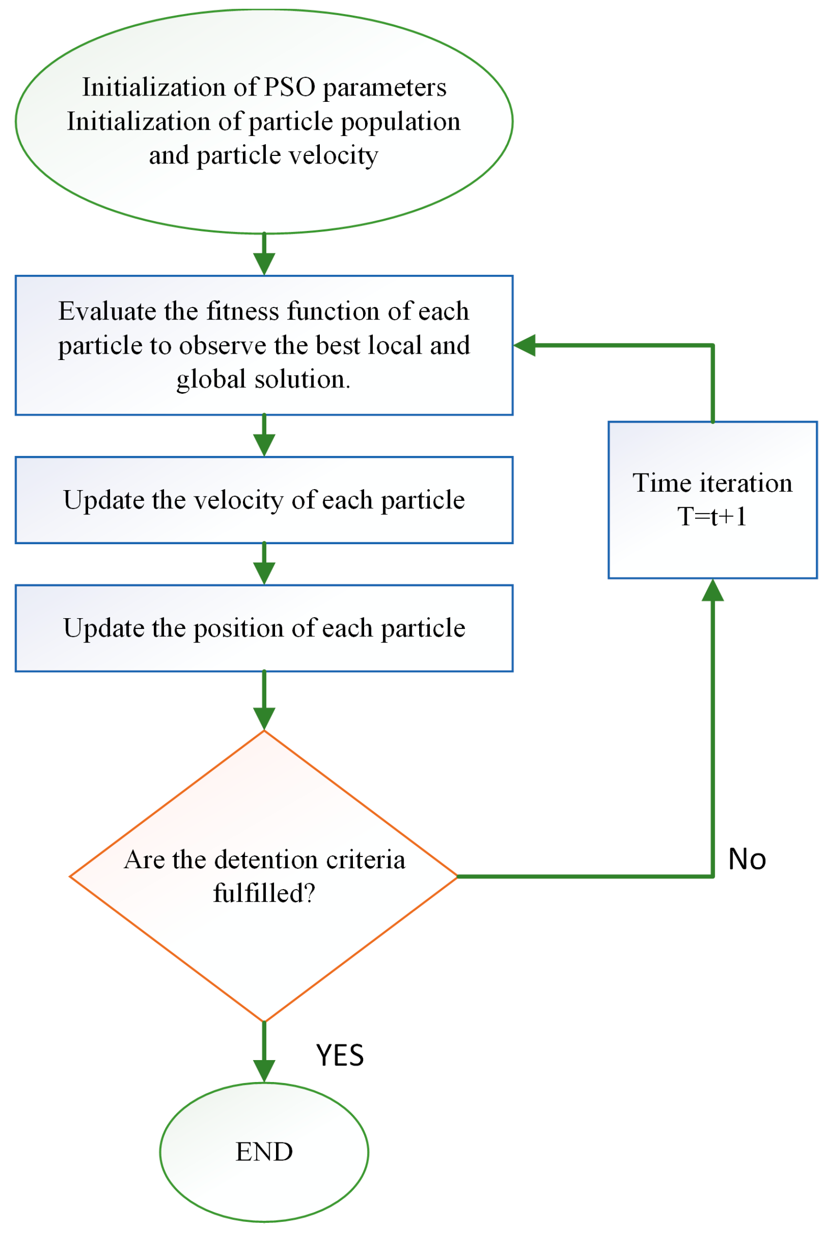
PSO is a metaheuristic optimization technique introduced by Kennedy and Eberhart in 1995. The intelligent, social, and experience-sharing behavior of flocks of birds and schools of fish inspires it. The PSO algorithm finds optimal solutions using a set of flying particles with velocities that are dynamically adjusted according to their historical performance, neighboring particles, and especially the "leader" in the search space. Each particle looks in a specific direction and then, by communicating with other particles, identifies the particle in the best location [44,45].
Figure 4 shows the basic flowchart of the PSO algorithm.
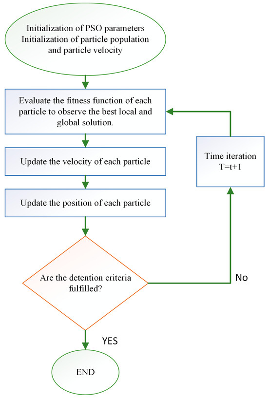
Figure 4.
PSO flowchart.
2.1.4. PSO Parameter Optimization
The proper configuration of the parameters of the PSO algorithm is crucial for maximizing its efficiency and effectiveness in finding optimal solutions. In the PSO algorithm, several parameters influence the behavior of the swarm and the quality of the solution, as follows:
- Inertia coefficient (w)—This parameter regulates the influence of the particle’s previous velocity when calculating the new velocity value. It has a direct impact on the scanning capability and the convergence speed. A suitable inertia value allows the PSO to achieve a good initial scan while gradually adjusting the approach toward the optimal solution.
- Cognitive and social acceleration coefficients (c1 and c2)—These coefficients determine the degree of influence exerted by individual knowledge and collective knowledge on each particle. Coefficient c1 regulates the influence of the best position reached by the particle to guide its new direction, and coefficient c2 regulates the influence of the cluster leader in the calculation of the search direction of the particle.
- Number of particles and generations—As in other population-based metaheuristic algorithms, the number of particles and generations affects the accuracy and effectiveness of the search. A larger number of particles and generations can improve the search for the optimal solution, but it also increases the computational cost. To avoid unnecessary processes, the number of generations was limited after the algorithm achieved satisfactory results in a small number of iterations.
Table 2 presents the final values of each parameter. These values were adjusted through testing, taking into account the following factors:
Table 2.
PSO control parameters.
- Influence on convergence speed—The configuration favored fast convergence towards high-quality solutions, avoiding oscillations and stagnation at local optima.
- Exploration capacity—The swarm sought to explore the search space wisely, avoiding premature convergence towards suboptimal solutions.
- Balance between exploration and exploitation—The final configuration offers an appropriate balance between exploring new areas of the search space and exploiting the best solutions.
Table 2 summarizes these values, and their tuning was performed to ensure fast convergence and prevent stalling at local optima. These values were tested and found to be effective in minimizing voltage THD and achieving high-quality solutions in reasonable computational times [46].
Once these optimal parameters were established, they were integrated into the ANFIS optimization process, achieving a synergy that improved the accuracy of switching angle prediction and THD minimization in multilevel inverter systems. The following section describes the procedure of combining PSO and ANFIS in the context of THD reduction.
2.2. Combination of ANFIS and PSO for the Optimization of Multilevel Inverters
The combination of ANFIS and PSO is an innovative strategy to improve the generation of switching angles in multilevel inverters. By leveraging the strengths of both techniques, improvements in training and THD minimization are achieved, overcoming the limitations of traditional methods.
The combination of ANFIS with PSO has the following advantages:
- Adaptability and learning of ANFIS—the ability to adapt to complex data and the capacity for continuous learning. By being trained with specific data sets, ANFIS can adjust its internal parameters to adapt to the system’s dynamics. This learning capability allows it to interpret complex patterns in the search for switching angles in the presence of some voltage variations or special cases.
- PSO optimization—the capability for global and dynamic optimization. Through the simulation of swarm behavior, PSO seeks to converge to optimal solutions in the search space. The combination of ANFIS and PSO leverages this optimization capability to further refine the adjustments made by ANFIS.
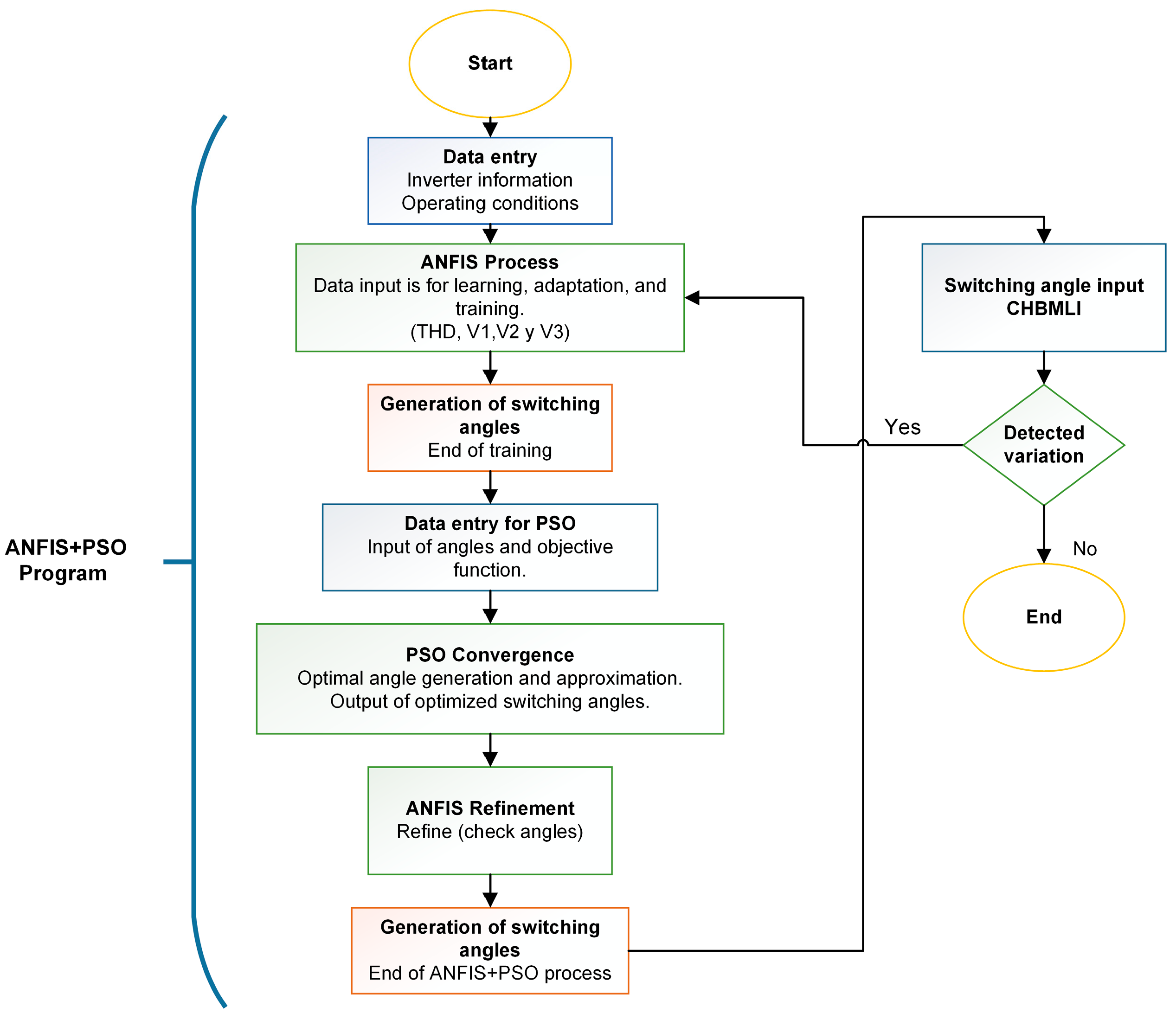
The combination of ANFIS and PSO generates suitable switching angles for various case studies, thus efficiently reducing THD. Figure 5 shows this process and the roles played by the ANFIS and PSO networks with the multilevel inverter. The complexity of the system and the interaction between these two techniques show a promising strategy to optimize CHBMLIs’ performance.
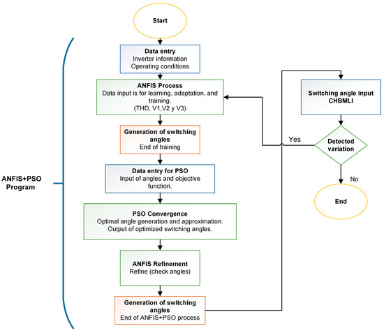
Figure 5.
Flow chart of the combination of ANFIS and PSO.
As can be seen, the ANFIS network interprets the data and adjusts their internal parameters according to learning-specific patterns. PSO optimizes these adjustments and looks for solutions that improve the quality of the output signal. Combining these techniques seeks to overcome the remaining shortcomings of traditional methods, offering more accurate and efficient solutions for multilevel inverters.
2.3. Problem Statement
The modulation of a multilevel inverter determines the THD ratios, voltage magnitude, and output frequency. A step waveform of the MLI output voltage is generated by solving the non-linear equations to obtain the switching angles of the semiconductor devices, as shown in Figure 6.
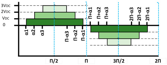
Figure 6.
Stepped waveform of a 7-level MLI.
To reduce the voltage THD in a CHBMLI, start by examining the stepped waveform of the output voltage using the Fourier series and expressing it in an equation with quarter-wave symmetry, as follows:
where n = 1, 3, and 5 are odd harmonics and is given by the following:
where:
n: 1, 3, 5 … 2N − 1 are odd harmonics.
N: number of switching angles per quarter cycle.
α: switching angle.
s: number of CD sources.
The level of harmonics in an output voltage waveform is crucial in determining its quality. IEEE 519 standard [38] recommends using up to 50 harmonics in THD calculations, as this allows for a good assessment of a system’s harmonic content. Therefore, the formula used to calculate the THD is limited to this value. Equation (4) presents the objective function outlining the THD formula.
where:
The angles must comply with the following restrictions:
where = number of switching angles per quarter cycle and are the switching angles. A problem arises when the input voltage at one of the CHBMLI sources varies. The previously calculated angles must be adjusted, resulting in a higher and poorer THD. Equation (4) is rewritten as follows:
where:
are input voltage sources and variants.
All possible scenarios must be calculated when the input sources vary, complicating the calculations and resulting in different angles. None of the classical methods or metaheuristic algorithms can adequately solve the SHE equations and generate switching angles in real time. Generally, switching angles are calculated for all required values using either method (classical or metaheuristic) and stored in look-up tables. This approach, called programmed SHE-PWM, is simple, but limited by the large amount of memory required. Different and innovative techniques that take advantage of AI’s benefits in power electronics have been explored in response to these limitations. AI techniques, such as fuzzy logic and ANFIS, have proven effective in applications such as motor drives and renewable energy systems. These tools offer flexible control and can successfully manage non-linear systems thanks to their ability to accurately interpolate and extrapolate data once properly trained [47].
2.4. Proposed Solution
CHBMLIs have proven effective in reducing THD and improving the delivered power quality. However, a significant challenge arises when the input voltage at any of the CHBMLI sources varies, which directly affects the previously calculated switching angles and can increase the THD, compromising system efficiency. In particular, in UPSs, where voltage variations are frequent due to battery discharge, it is crucial to maintain precise control over the switching angles to ensure a constant power quality and not affect the computers or sensitive equipment maintaining the UPS. The combination of the learning capability of artificial intelligence, through ANFIS, and the efficiency of optimization algorithms, represented by PSO, seeks to provide an innovative and effective solution to improve the accuracy of the generation and adjustment of switching angles, even in the face of voltage variations. This combination optimizes the switching angles in advance and enhances their real-time adaptation, improving the CHBMLI inverter output quality under varying conditions.
In this proposal, the switching angles are pre-determined offline using a PSO algorithm to find the optimal configuration to minimize harmonics. These angles are used to train the ANFIS network, which acts as an intelligent controller capable of dynamically adjusting the online switching angles according to the voltage variations occurring at the CHBMLI sources. This is particularly useful in a UPS environment, where voltage variations in the batteries, as they discharge, can significantly affect the THD if the angles are not properly adjusted. The effectiveness of this technique will be evaluated primarily through training the ANFIS network under various voltage variation conditions, simulating different levels of battery discharge. The ANFIS network aims to accurately learn the optimal switching angles for each case, reducing the errors to values close to zero. The network’s performance will be measured by experiments covering a wide range of operating conditions, ensuring that the model responds appropriately to any possible variations in the voltages of the sources.
Once the training is completed, the angles obtained will be used in a simulated CHBMLI inverter. The results of the simulated inverter will be compared with the THD values obtained during the training of the ANFIS network to analyze the model’s accuracy and observe the variations between the THD calculated by the network and that generated in the simulation. This analysis will validate the proposal’s effectiveness, demonstrating that the ANFIS network can predict and adjust the switching angles with a high accuracy, even in the face of variations in the voltages of the sources, effectively minimizing the THD.
2.5. Case of Study
As mentioned above, the case study is a UPS using a seven-level cascaded multilevel inverter. This type of inverter requires three independent power supplies, which, in this case, are three battery packs. As the batteries discharge, they will give different voltage levels. LifePo4 S17 batteries (62 V) were used to obtain an output voltage of 131 VRMS or 186 V peak, emulating the load of a computer in critical applications, such as bank or hospital databases. Five critical load percentages were considered to train the ANFIS network based on the voltages observed during battery discharge, as shown in Table 3.
Table 3.
Percentage and important voltages of the case study.
These voltages are important, because the performance of LifePo4 batteries shows a significant trend when discharging. At 95% charge, the voltage in the cells undergoes an apparent change; after this point, the discharging of the battery is constant and shows little variation. Therefore, it was decided to observe the 50% load so that the network could better understand the behavior in this stable range. However, at 15% charge, a drastic change in voltage is observed. The critical points where a battery shows the most stable behavior are between 95% and 15% charge. At 5%, the battery is practically empty. Still, for the ANFIS network to be properly trained and predict the possible THD in this scenario, this load percentage was included in the analysis.
Considering these five critical points in the battery discharge, multiple combinations and possible scenarios can be obtained to train the ANFIS network. For this reason, experiments were designed to identify the most relevant scenarios. It is important to note that, due to the type of modulation used, the battery packs were not discharged in a balanced manner. This power consumption had to be considered when designing the experiments to capture all possible scenarios. Finally, after incorporating all these variables, the design of experiments revealed that 35 experiments were needed to train the network properly. Table 4 shows the 35 experiments and the different voltages for the subsequent training.
Table 4.
Percentages and important voltages of the case study.
Table 4 presents the 35 experiments and the different voltages used in training the system. From these data, an ANFIS network was developed in combination with the PSO algorithm in MATLAB. The process included the initial programming of the ANFIS network, followed by the integration of the PSO and the design of an objective function aimed at reducing the THD.
3. Results
3.1. Network Training
The resulting MATLAB code was designed to train the ANFIS network with PSO using the switching angles and the respective THD measurements, allowing for detailed observations of the behavior during the training process. Throughout the development, continuous iterations and adjustments were carried out to optimize the convergence of the network and improve its predictive capability. The scheduling process involved tuning the parameters of the objective function to ensure an optimal performance during training. As mentioned, this process consisted of the following two stages: the training stage and the testing stage. In the training stage, the network was trained with 35 case studies to learn and determine the switching angles that minimized the THD in the inverter. Figure 7 shows the convergence process and angle distribution during training, specifically for Experiment 1.
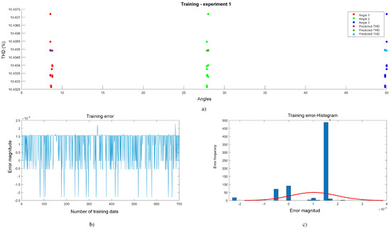
Figure 7.
Training stage experiment 1. (a) THD vs. angles, (b) error vs. training data, and (c) amount of data vs. error.
Figure 7 shows how the switching angles converged to specific values and how they correlated with the THD. For this case study, 1000 samples (sets of angles) were used in these tests, distributing 70% (700 samples) for network training and 30% (300 samples) for testing. This number of samples is sufficient to allow the network to converge effectively, as it provides adequate data for the model to analyze and learn the relationships between angles and THD. With a training set of 700 samples, the network can observe patterns and achieve convergence, resulting in an improved performance. This angle generation was performed randomly, complying with the established restrictions. However, it also helped the system to be better oriented to the PSO to find better angles and obtain errors close to zero. An important point of the procedure was the order of the execution of the network training, as follows: first, the introduction of the training data to the network was carried out, and after this process, the search for the set of switching angles that minimized the THD was started.
Continuing with Figure 7, Graph a shows how the switching angles converged to specific values, as follows: the first angle converged to approximately 8°, the second to between 27° and 28°, and the third to between 49° and 50°. These angles converged to a minimum THD of 10.43%, thus approaching the results reported in the literature for a seven-level MLI. In Graph b, which shows the training errors, located in the lower left corner, with the help and guidance of the PSO, the variations decrease, obtaining deviations of ±0.002. This shows a significant improvement in convergence and a closer approximation to the global minimum. In Graph c, which is of a Gaussian distribution (bottom right corner), it can be seen how the errors tend to approach 0. However, many of these errors fell within +0.0015, and they were minimal errors that did not affect the system and managed to converge to the result. Although it is observed that there are errors that fell outside the Gaussian bell, it is considered that these errors did not have a critical impact on the overall performance.
In the second stage, known as the testing stage, the results obtained in the training stage were validated. This made it possible to evaluate the network’s ability to adjust the switching angles in real time, optimizing the output signal quality even when input voltage variations occurred. The following figure shows the results of the data testing stage.
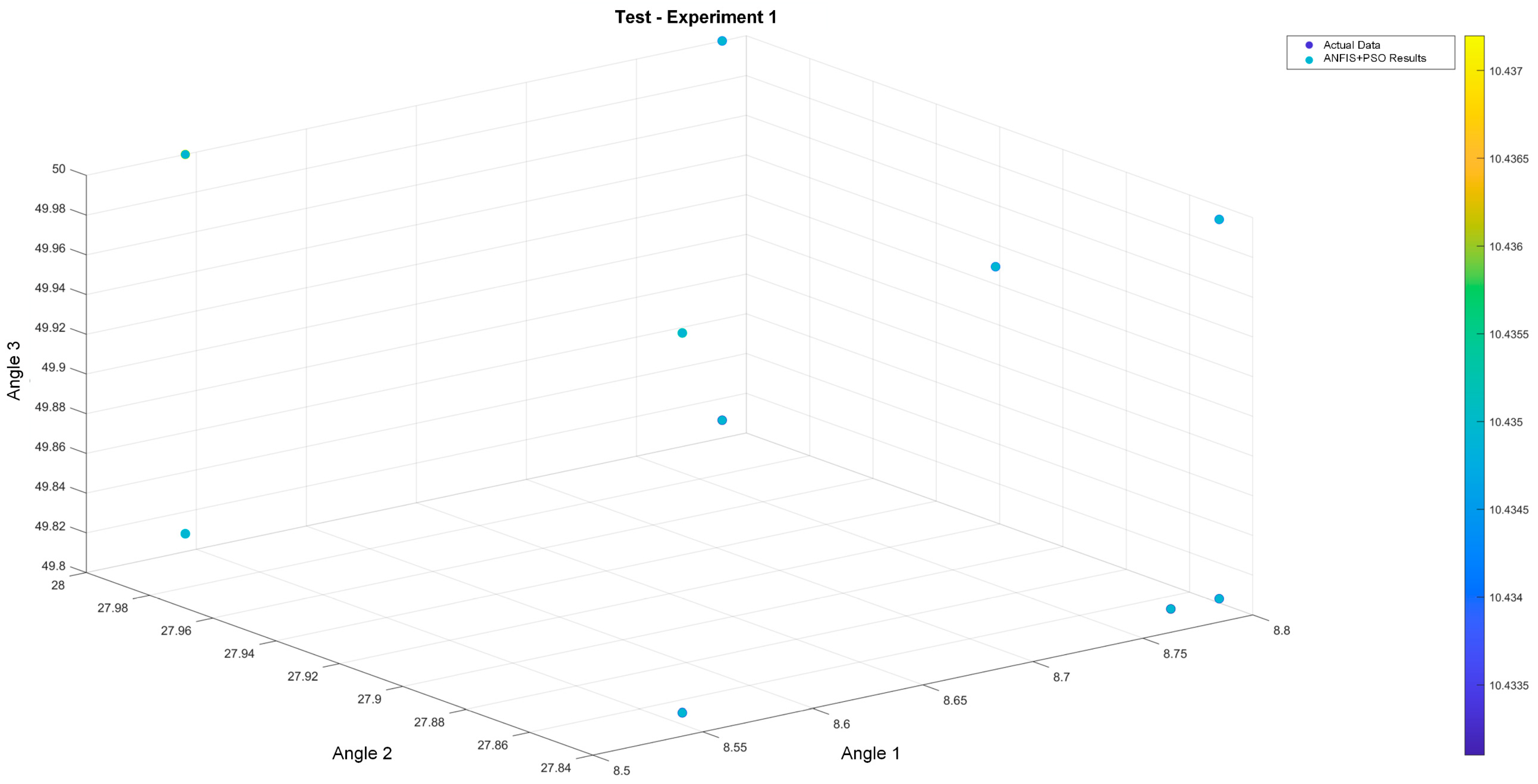
Figure 8 shows the three switching angles obtained in the testing phase. In the three-dimensional plot, the actual data are shown together with the results of the ANFIS with PSO. As can be seen, the angles do not show significant variations, indicating that they are converging accurately to the expected values, with errors close to ±0.002. On the right side of the figure, a color spectrum representing the THD obtained by the sets of angles is shown. The shades, mostly concentrated in a blue range, confirm that the deviations are minimal and that the calculated angles allow for approaching the expected minimum THD, as mentioned above. These small color variations reflect deviations between 0.0015 and 0.002, making it difficult to differentiate between shades in the color spectrum. To observe how the deviations and errors in the testing stage perform, graphs are shown in Figure 9.
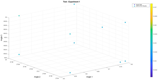
Figure 8.
Three-dimensional visualization of switching angles obtained by ANFIS.
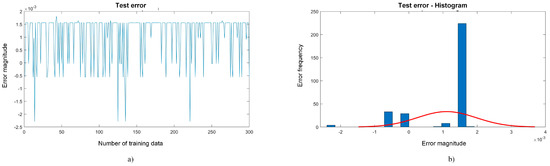
Figure 9.
Error graphs testing phase.
Three hundred test data were used in Figure 9. In Plot a, deviations of ±0.002 persist, which shows a good performance, as mentioned before. Turning to Gaussian Plot b, the distribution of errors in many of these fall within 0.0015, which shows better behavior than that in the training stage.
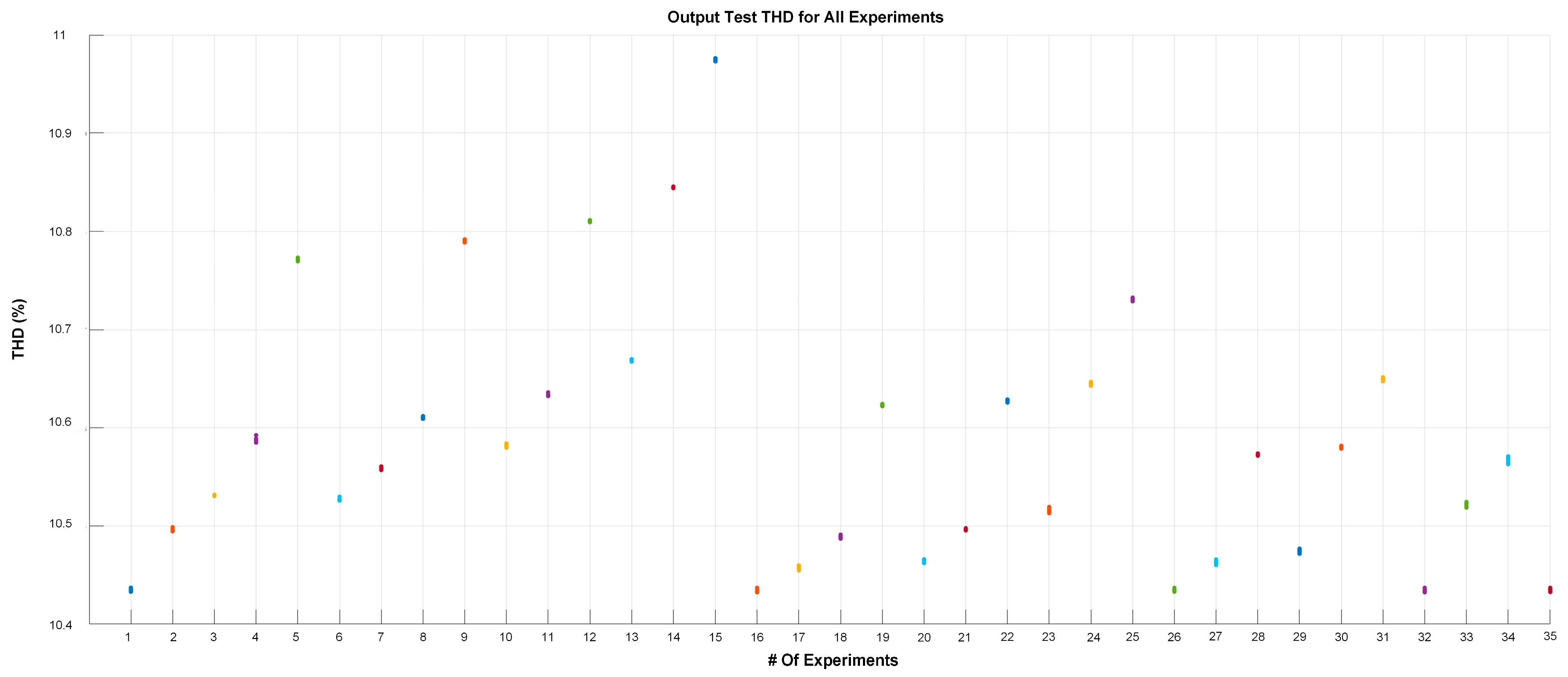
Table 5 shows that the switching angles obtained varied from case to case, while others remained relatively constant. This highlights the importance of accuracy during training and data collection. Using a different angle than the minimum found in another case can raise the THD, highlighting the need for accuracy in angle selection. The minimum THD found in the cases was around 10%. Experiment 15 had a slightly higher THD than the others, with a THD of 10.9%. This variation of almost 1% shows that the system still performed well and was close to the minimum found. The analysis of these results confirms the effectiveness of the ANFIS network with PSO in optimizing the switching angles in the seven-level CHBMLI. The results show that the ANFIS network can adjust to different input conditions, keeping the THD at acceptable levels and close to the calculated minimum. Figure 10 shows the results obtained by the ANFIS network to evaluate and check the quality of the network training.
Table 5.
Angles and THD obtained in the ANFIS network.
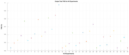
Figure 10.
THD obtained at the output of the network.
Figure 10 shows the experiments in different colors and the THD obtained from the training. Compared with the results in Table 4, the results obtained by the ANFIS network are pretty similar to what is predicted in the table, indicating an excellent overall performance of the model. Some cases show sparse points, meaning that the network needed more iterations to converge to the minimum possible THD. This is not necessarily negative, it just reflects that, depending on the training and adjustments made, the iteration and adjustments can be further improved. Overall, the errors observed in the ANFIS network were ±0.002, which confirms that the angles and THD values obtained were consistent, with minimal variations between simulations. This is evidence that the ANFIS network was effectively trained and tuned.
3.2. MATLAB Simulation of the Case Study
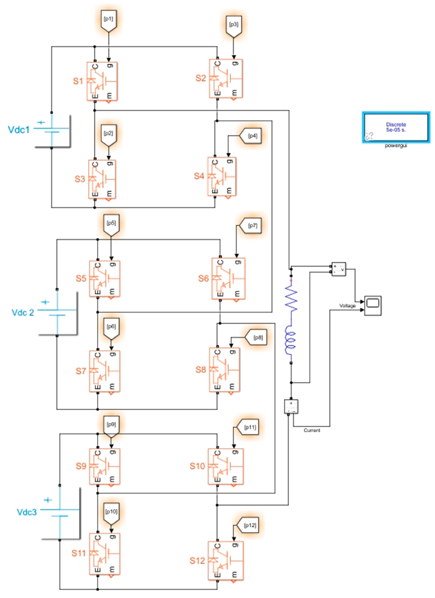
Once the ANFIS network training was completed, the next step was to develop the seven-level CHBMLI simulation in MATLAB R2021a Simulink. The objective of this simulation was to compare the THD results obtained during the network’s training with the simulated values at an inverter, using the angles calculated by the ANFIS network for each case under study. Figure 11 shows the seven-level CHBMLI model implemented in Simulink R2021a.
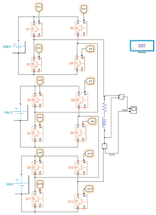
Figure 11.
Seven-level CHBMLI in MATLAB Simulink.
The voltage sources and switching angles were varied for the simulation, using Experiment 1 to configure and observe the inverter output, as detailed in the figure below.
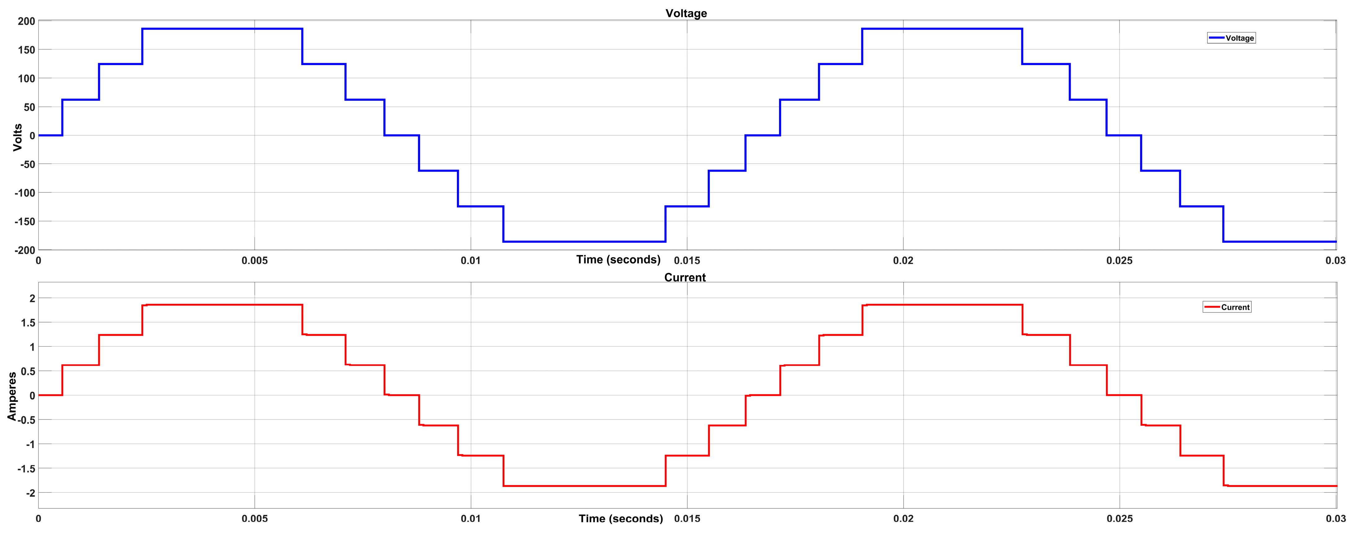
Figure 12 shows a voltage output of 186 V and a current of 1.86 A, with a connected load of 100 ohms and 100 microhenries. This confirms that the inverter produces the expected voltage and current levels, which validates the correct operation of the CHBMLI under the simulated conditions. Subsequently, the Simulink R2021a Powergui FFT Analysis Tool was used to analyze the harmonic content and THD of the generated signal, as shown in Figure 13.
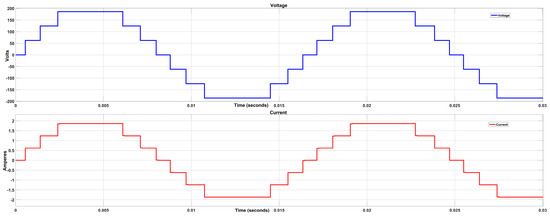
Figure 12.
CHBMLI voltage and current in MATLAB Simulink.
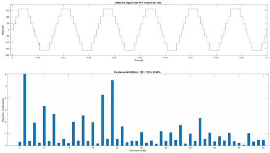
Figure 13.
Harmonic content and THD of the case study voltage.
Figure 13 shows the harmonic content and the resulting voltage THD, which was 10.46%. This value has a difference of only 0.03% compared to the THD calculated by the ANFIS network, demonstrating the network’s accuracy in predicting the switching angles. It should be noted that the minimal differences observed may be due to the approximation used in the simulation, where only two decimal places were considered for the switching angles. In a realistic environment, this simplification is common, as components such as IGBTs or MOSFETs cannot switch with an accuracy of more than two decimal places. Despite this, the performance of the ANFIS network was highly satisfactory.
4. Discussion
Finally, simulations of the other experiments were performed, obtaining the corresponding THDs, with the results presented in Table 6.
Table 6.
%THD training vs. %THD simulation.
Table 6 shows that, in most cases, the THD obtained in the training and simulation varied slightly, generally within a range of 0.05%. In some experiments, the THD coincided with that obtained during training; in others, it exceeded this variation margin. However, the largest observed deviation did not exceed 0.2%, which is still acceptable, but should be considered for further analysis. It should be noted that this deviation occurred only in a few cases.
An interesting aspect is that, in some experiments, the THD obtained in the simulation was lower than that calculated during training. This suggests that the system efficiently minimized THD under certain operating conditions. However, cases were also identified where the simulated THD was slightly higher than the calculated THD, although, as mentioned above, these differences were within an acceptable range of ±0.2%.
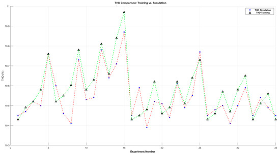
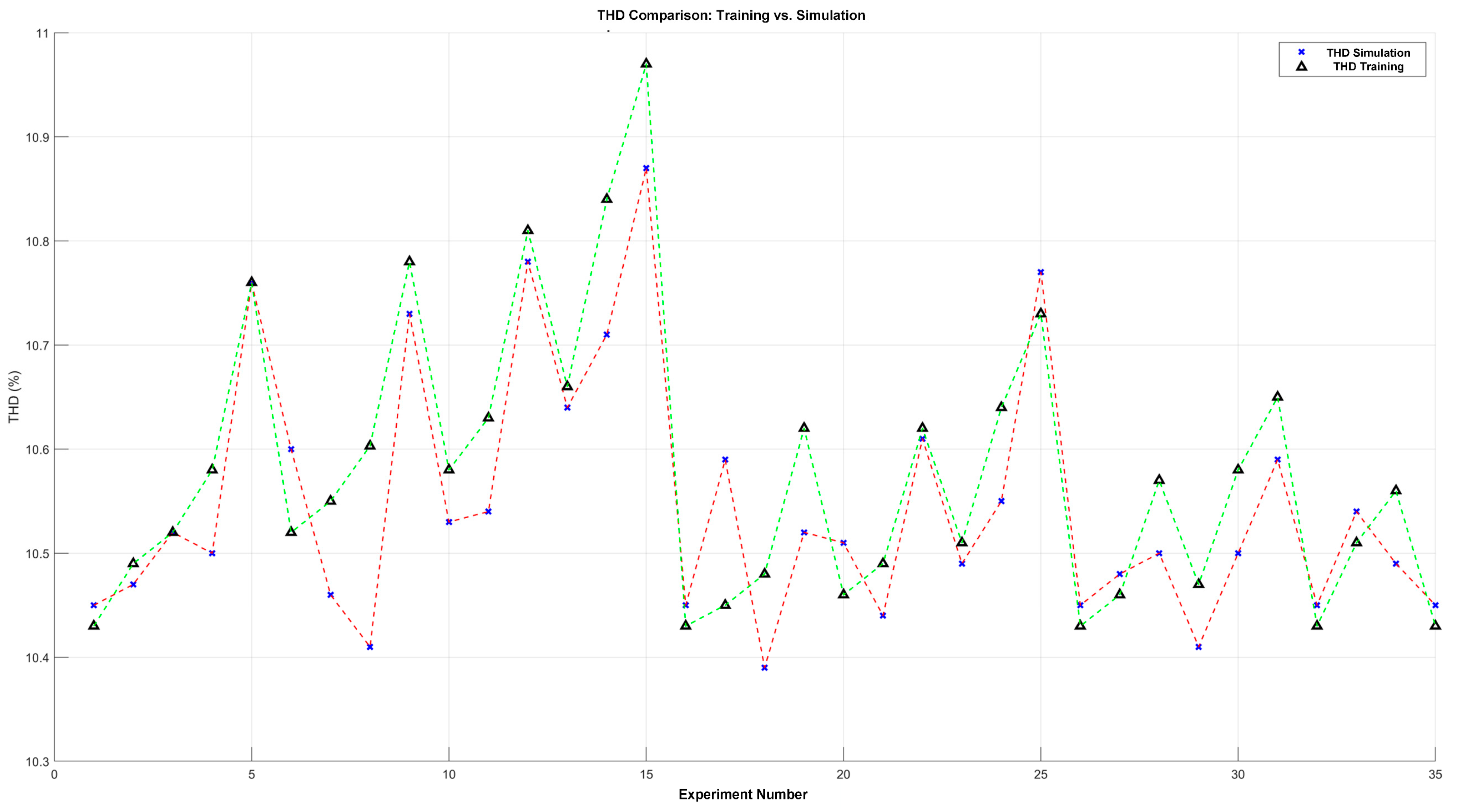
Figure 14.
Comparison of %THD: training vs. simulation.
In Figure 14, the x-axis represents the number of experiments and the y-axis shows the percentage of THD obtained. As previously indicated, in most cases, the differences between the calculated THD (marked with the red line) and the THD obtained in the simulation (marked with the green line) were minimal. Only in a few cases was a larger variation observed, with Experiment 8 having the largest difference, close to 0.2%.
Furthermore, the standard deviation between the %THD in training and the %THD in simulation was 0.06. This low standard deviation value confirms that the optimization process effectively minimized the THD in most experiments. Furthermore, the graph allows us to identify which experiments showed a simulated THD lower than the calculated one, indicating an improved system performance, and which ones showed a slightly higher THD. Even so, it is important to highlight that these differences were small and did not exceed 0.2%. This indicates that the optimization process effectively found the minimum THD in most selected experiments.
However, in all cases, the simulated THD values slightly exceeded the 8% THD defined by the IEEE 519 standard [38]. An effective reduction in THD in the switching stage allows smaller and less complex filters to be designed, thus optimizing the system.
This proposed approach demonstrates that ANFIS with PSO allows low THD levels to be achieved under simulation conditions and facilitates a more efficient implementation in industrial environments with voltage fluctuations. The optimized switching angles generated by ANFIS with PSO successfully reduced the harmonic content. This approach simplifies the design requirements by minimizing the size and complexity of the filtering stage, which is advantageous for UPS systems faced with variable voltage inputs. In addition, the adaptive capabilities of ANFIS, enhanced by the optimization power of PSO, allow for real-time adjustments in switching angles as voltage conditions fluctuate, ensuring that the inverter consistently maintains high-quality output without the need for pre-calculated look-up tables.
To demonstrate the effectiveness of the proposed network, Table 7 presents a comparative summary of the voltage THD values achieved in different studies using multilevel inverters, as described in the literature. It should be noted that finding works using seven-level cascaded multilevel inverters with ANFIS combined with some metaheuristic techniques was complex. For this reason, the table includes several relevant studies to illustrate the variations in the results and applications reported in the literature. Furthermore, it is emphasized that there are no fully comparable case studies due to the diversity of ANFIS applications in specific contexts.
Table 7.
Comparison of %Voltage THD in the literature.
Table 7 compares the voltage THDs obtained in the literature with those obtained in this study. It is observed that the studies with the highest THD percentage are reference [15], which uses a five-level inverter, where the THD is notably higher due to the lower number of levels, and reference [20], with nine levels, which highlights the influence of the number of levels on the THD reduction. In references [17,28], both studies use seven-level inverters, similar to the proposed method. However, the THD obtained in this study was slightly higher than that in these cases. First, it is important to note that the differences in THD were small, from 1 to 2%, which is still favorable. The main difference is that reference [17] only analyzed up to harmonic 20, while this study considered up to harmonic 49, complying with IEEE 519 standard [38]. A lower harmonic analysis tends to produce a lower THD value. In reference [28], seven switching angles were employed, contributing to a decrease of approximately 2% in THD compared to the results obtained in this work. The remaining references, with THD values between 0.78% and 4%, present significant differences due to several factors. In some cases, additional filters were used to reduce the THD at the inverter output. In addition, studies using inverters from 9 to 31 levels achieved a significant reduction in THD; however, these inverters presented a higher complexity in both the equations and the control of the switching angles. It is worth mentioning that studies with lower THD mainly used ANFIS with classical (Gradient Descent) methods. In future work, inverters with a greater number of levels or the incorporation of small filters could be explored, which would further reduce the THD and evaluate the improvement that can be obtained.
5. Conclusions
This paper presented an approach based on combining AI techniques, specifically using ANFIS optimized using the PSO algorithm, to minimize the voltage THD in a seven-level CHBMLI. The results showed this approach’s effectiveness in optimizing the switching angles, achieving a reduced THD compared to conventional methods. Throughout the experiments, it was observed that the combination of ANFIS and PSO not only provided a voltage THD close to the values calculated during training, but, in some cases, exceeded expectations, obtaining lower THD values in the simulations. This highlights the efficiency of metaheuristic algorithms compared to traditional methods, often based on analytical or gradient descent approximations. Metaheuristic methods’ higher accuracy and flexibility, such as PSO, allow for a greater adaptability to different operating conditions.
The observed variations in the results, within ±0.1%, demonstrate that the ANFIS model with PSO can handle uncertainty and efficiently adjust switching angles, even in complex scenarios. However, it was identified that some experiments showed a slight discrepancy compared to the trained values, which can be attributed to the decimal precision used in the physical devices, such as IGBTs or MOSFETs, limiting the switching accuracy.
The comparative analysis also underscores the proposed method’s competitive performance relative to other studies. While THD levels may differ due to the harmonic analysis range or additional filters, the proposed method achieved comparable results without complex filtering stages, obtaining a THD of 10%. This provides a significant advantage in design simplicity and cost efficiency for UPS systems and other power applications.
Finally, the integration of AI into multilevel inverters, particularly the use of ANFIS optimized with PSO, represents a significant advance in improving the performance of these systems, providing an efficient and robust alternative for voltage THD minimization. The results obtained in this study are encouraging and suggest that this approach can be applied in various power systems, including those powered by renewable energy sources and in high-precision applications such as UPS systems. The ability to dynamically optimize switching angles as a function of voltage variations and other operating conditions positions this method as a viable and effective solution for the future of power electronics. Future work could explore higher-level inverters or additional filtering to reduce the THD further, reinforcing the applicability of this method in renewable energy systems and high-precision applications.
Author Contributions
Conceptualization, O.S.V., J.A.A. and S.E.D.L.A.; data curation, O.S.V. and M.B.; formal analysis, O.S.V. and J.A.A.; funding acquisition, L.G.V.V., M.B. and R.E.L.-P.; investigation, J.A.A. and S.E.D.L.A.; methodology, O.S.V., M.B. and J.A.A.; project administration, S.E.D.L.A.; resources, L.G.V.V. and R.E.L.-P.; software, O.S.V.; supervision, L.G.V.V., J.A.A. and S.E.D.L.A.; validation, O.S.V.; visualization, R.E.L.-P. and J.A.A.; writing—original draft, O.S.V., J.A.A. and S.E.D.L.A.; writing—review and editing, L.G.V.V., M.B., R.E.L.-P. and S.E.D.L.A. All authors have read and agreed to the published version of the manuscript.
Funding
This research received no external funding.
Data Availability Statement
Data are contained within the article.
Acknowledgments
M.B. thanks CONAHCYT for her Catedra Research Position with ID 71557 and CENIDET for its hospitality and support.
Conflicts of Interest
The authors declare no conflicts of interest.
Abbreviations
| ABC | Artificial Bee Colony |
| ADELINE | Adaptive Linear Neuron |
| AI | Artificial Intelligence |
| ANN | Artificial Neural Networks |
| ANFIS | Adaptive Neuro-Fuzzy Inference System |
| BSMC | Backstepping Sliding Mode Control |
| CHBMLI | Cascaded H-bridge multilevel inverter |
| DC | Direct Current |
| DTC | Direct Torque Control |
| EPO | Emperor Penguin Optimization |
| FFT | Fast Fourier Transform |
| FLC | Fuzzy Logic Controller |
| GA | Genetic Algorithm |
| GD | Gradient Descent |
| LS-PWM | Level-shifted PWM |
| LSTM | Long Short-Term Memory |
| MWH | Modified Widrow–Hoff |
| NF | Neuro Fuzzy |
| NR | Newton–Raphson |
| PEC | Packed E-Cell |
| P&O | Perturb and Observe |
| PSO | Particle Swarm Optimization |
| PWM | Pulse Width Modulation |
| RMS | Root Mean Square |
| SAPF | Series Active Power Filter |
| SHAF | Shunt Hybrid Active Power Filter |
| SHE | Selective Harmonic Elimination |
| SRF | Synchronous Reference Frame |
| THD | Total Harmonic Distortion |
| UPS | Uninterruptible Power Supply |
References
- Aamir, M.; Ahmed Kalwar, K.; Mekhilef, S. Review: Uninterruptible Power Supply (UPS) system. Renew. Sustain. Energy Rev. 2016, 58, 1395–1410. [Google Scholar] [CrossRef]
- Keyan, S.; Dehong, X. Chapter 15—Operation and control of uninterruptible power supply system. Control. Power Electron. Convert. Syst. 2024, 4, 457–509. [Google Scholar]
- Nasiri, A.; Hamidi, S.A. Uninterruptible Power Supplies. In Power Electronics Handbook (Fourth Edition); Rashid, M.H., Ed.; Butterworth-Heinemann; University of Wisconsin-Milwaukee: Milwaukee, WI, USA, 2018; pp. 641–657. [Google Scholar]
- Godoy, M.P.; Uberti, V.A.; Abaide, A.d.R.; Guidali, G.D.; Prade, L.R.; Keller, A.L. Identifying and reducing harmonic distortion in an industrial uninterruptible power supply system. In Proceedings of the 2020 6th International Conference on Electric Power and Energy Conversion Systems (EPECS), Istanbul, Turkey, 5–7 October 2020; pp. 34–39. [Google Scholar]
- Katir, H.; Abouloifa, A.; Noussi, K.; Lachkar, I.; Giri, F. Cascaded H-Bridge Inverters for UPS Applications: Adaptive Backstepping Control and Formal Stability Analysis. IEEE Control Syst. Lett. 2022, 6, 145–150. [Google Scholar] [CrossRef]
- Kabalci, E. Multilevel Inverters Introduction and Emergent Topologies. In Multilevel Inverters; Kabalci, E., Ed.; Academic Press: Cambridge, MA, USA, 2021; pp. 1–27. [Google Scholar]
- Choudhury, S.; Bajaj, M.; Dash, T.; Kamel, S.; Jurado, F. Multilevel Inverter: A Survey on Classical and Advanced Topologies, Control Schemes, Applications to Power System and Future Prospects. Energies 2021, 14, 5773. [Google Scholar] [CrossRef]
- Azuela, J.H.S.; Cortés, F.R. Inteligencia Artificial Aplicada a Robótica y Automatización; Grupo, A., Ed.; S.A.Dec.V.: México City, Mexico, 2020; p. 382. [Google Scholar]
- Ponce, P. Inteligencia Artificial—Con Aplicaciones a la Ingeniería; Alfaomega: Mexico City, Mexico, 2010; p. 376. [Google Scholar]
- Vas, P. Artificial-Intelligence-Based Electrical Machines and Drives Application of Fuzzy, Neural, Fuzzy-Neural, and Genetic-Algorithm-based Techniques; Oxford Science Publicactions: Oxford, UK, 1999. [Google Scholar]
- Blum, C.; Roli, A.; Alba, E. An Introduction to Metaheuristic Techniques. In Parallel Metaheuristics A New Class of Algorithms; Zomaya, A.Y., Alba, E., Eds.; A John Wiley & Sons, Inc.: Hoboken, NJ, USA, 2005. [Google Scholar]
- Shuai, Z.; Frede, B.; Huai, W. Chapter 8—Artificial Intelligence–Assisted Data-Driven Control of Power Electronics Systems; Academic Press: Cambridge, MA, USA, 2024; Volume 4, pp. 219–239. [Google Scholar]
- Shihabudheen, K.V.; Pillai, G.N. Recent advances in neuro-fuzzy system: A survey. Knowl.-Based Syst. 2018, 152, 136–162. [Google Scholar] [CrossRef]
- de Campos Souza, P.V. Fuzzy neural networks and neuro-fuzzy networks: A review the main techniques and applications used in the literature. Appl. Soft Comput. 2020, 92, 106275. [Google Scholar] [CrossRef]
- Muthuramalingam, M.; Manoharan, P.S. Comparative analysis of distributed MPPT controllers for partially shaded stand alone photovoltaic systems. Energy Convers. Manag. 2014, 86, 286–299. [Google Scholar] [CrossRef]
- Karuppusamy, P.; Natarajan, A.M.; Vijeyakumar, K.N. An Adaptive Neuro-Fuzzy Model to Multilevel Inverter for Grid Connected Photovoltaic System. J. Circuits Syst. Comput. 2015, 24, 1550066. [Google Scholar] [CrossRef]
- Nageswara Rao, G.; Chandra Sekhar, K.; Sangameswararaju, P. An Effective Technique for Reducing Total Harmonics Distortion of Multilevel Inverter. J. Intell. Syst. 2018, 27, 433–446. [Google Scholar] [CrossRef]
- Sudha Letha, S.; Thakur, T.; Kumar, J. Harmonic elimination of a photo-voltaic based cascaded H-bridge multilevel inverter using PSO (particle swarm optimization) for induction motor drive. Energy 2016, 107, 335–346. [Google Scholar] [CrossRef]
- Hemachandu, P.; Reddy, V.C.V. A Critical Evaluation of Advanced Multi-Carrier Modulation Scheme for 15-Level Inverter via PSO-PID Controller. Procedia Technol. 2016, 23, 240–247. [Google Scholar] [CrossRef]
- Francis, R.; Meganathan, D. An Improved ANFIS with Aid of ALO Technique for THD Minimization of Multilevel Inverters. J. Circuits Syst. Comput. 2018, 27, 1850193. [Google Scholar] [CrossRef]
- Das, S.R.; Ray, P.K.; Mohanty, A.; Das, H. Performance evaluation of multilevel inverter based hybrid active filter using soft computing techniques. Evol. Intell. 2019, 14, 345–355. [Google Scholar] [CrossRef]
- Lova Lakshmi, T.; Gopichand Naik, M. Soft-Computing Techniques for Voltage Regulation of Grid-Tied Novel PV Inverter at Different Case Scenarios. In Soft Computing and Signal Processing; Advances in Intelligent Systems and Computing; Springer: Singapore, 2019; pp. 181–190. [Google Scholar]
- Das, S.R.; Ray, P.K.; Mishra, A.K.; Mohanty, A. Performance of PV integrated multilevel inverter for PQ enhancement. Int. J. Electron. 2020, 108, 945–982. [Google Scholar] [CrossRef]
- Toumi, T.; Allali, A.; Meftouhi, A.; Abdelkhalek, O.; Benabdelkader, A.; Denai, M. Robust control of series active power filters for power quality enhancement in distribution grids: Simulation and experimental validation. ISA Trans. 2020, 107, 350–359. [Google Scholar] [CrossRef]
- Bihari, S.P.; Sadhu, P.K. Design analysis of high level inverter with EANFIS controller for grid connected PV system. Analog. Integr. Circuits Signal Process. 2020, 103, 411–424. [Google Scholar] [CrossRef]
- Mehrasa, M.; Babaie, M.; Zafari, A.; Al-Haddad, K. Passivity ANFIS-Based Control for an Intelligent Compact Multilevel Converter. IEEE Trans. Ind. Inform. 2021, 17, 5141–5151. [Google Scholar] [CrossRef]
- Rupesh, M.; Vishwanath, D.T.S. Fuzzy and ANFIS Controllers to Improve the Power Quality of Grid Connected PV System with Cascaded Multilevel Inverter. Int. J. Electr. Electron. Res. 2021, 9, 89–95. [Google Scholar] [CrossRef]
- Nikouei, S.Y.; Dehkordi, B.M.; Niroomand, M. A Genetic-Based Hybrid Algorithm Harmonic Minimization Method for Cascaded Multilevel Inverters with ANFIS Implementation. Math. Probl. Eng. 2021, 2021, 15. [Google Scholar] [CrossRef]
- Muralikumar, K.; Ponnambalam, P. Comparison of Fuzzy and ANFIS Controllers for Asymmetrical 31-Level Cascaded Inverter With Super Imposed Carrier PWM Technique. IEEE Access 2021, 9, 82630–82646. [Google Scholar] [CrossRef]
- Banu, J.B.; Jeyashanthi, J.; Ansari, A.T. DTC-IM drive using adaptive neuro fuzzy inference strategy with multilevel inverter. J. Ambient Intell. Humaniz. Comput. 2021, 13, 4799–4821. [Google Scholar] [CrossRef]
- Goggi Narasimha; Gummadavelli Naveen; Shireesha, K.; Kartheek, K.; Kumar, B.P. Anfis based power quality improvement in cascaded h-bridge multilevel inverter. Int. Res. J. Mod. Eng. Technol. Sci. 2022, 4, 10. [Google Scholar]
- Loaena, Y.G.; Biru, I.G.; Reddy, C.S.; Iqbal, K. Design and Analysis of Front Side Modular Multilevel Converter for Smart Transformer in 15 kV Arba Minch Distribution Network Using Diverse Controllers and Multicarrier Modulation. J. Eng. 2022, 2022, 7678241. [Google Scholar] [CrossRef]
- Potturi, S.; Reddy, K.J.; Dash, R.; Jena, R.; Subburaj, V.; Dhanamjayulu, C.; Sun, X. Direct Torque Control of Induction Motor Using ConvLSTM Based on Gaussian Pillbox Surface. Math. Probl. Eng. 2022, 2022, 4408271. [Google Scholar] [CrossRef]
- Chenchireddy, K.; Jegathesan, V. ANFIS Based Reduce Device Count DSTATCOM. J. Appl. Sci. Eng. 2023, 26, 1657–1666. [Google Scholar] [CrossRef]
- Patil, M.D.; M., P.B. Performance Enhancement of Multi-Level Inverters with PSO-ANFIS Computational Techniques. J. Electr. Syst. 2024, 20, 4263–4272. [Google Scholar]
- Vargas, O.S.; Aldaco, S.E.D.L.; Alquicira, J.A.; Vela-Valdés, L.G.; Núñez, A.R.L. Adaptive Network-Based Fuzzy Inference System (ANFIS) Applied to Inverters: A Survey. IEEE Trans. Power Electron. 2024, 39, 869–884. [Google Scholar] [CrossRef]
- Prasad, T.N.; Devakirubakaran, S.; Muthubalaji, S.; Srinivasan, S.; Karthikeyan, B.; Palanisamy, R.; Bajaj, M.; Zawbaa, H.M.; Kamel, S. Power management in hybrid ANFIS PID based AC–DC microgrids with EHO based cost optimized droop control strategy. Energy Rep. 2022, 8, 15081–15094. [Google Scholar] [CrossRef]
- 519-2022; IEEE Recommended Practice and Requirements for Harmonic Control in Electric Power Systems. IEEE Poer and Energy Society: New York, NY, USA, 2022.
- Jang, J.-S.R. ANFIS: Adap tive-Ne twork-Based Fuzzy Inference System. IEEE Trans. Syst. Man Cybern. 1993, 23, 665–685. [Google Scholar] [CrossRef]
- Sobhani, J.; Najimi, M.; Pourkhorshidi, A.R.; Parhizkar, T. Prediction of the compressive strength of no-slump concrete: A comparative study of regression, neural network and ANFIS models. Constr. Build. Mater. 2010, 24, 709–718. [Google Scholar] [CrossRef]
- Karaboga, D.; Kaya, E. Adaptive network based fuzzy inference system (ANFIS) training approaches: A comprehensive survey. Artif. Intell. Rev. 2018, 52, 2263–2293. [Google Scholar] [CrossRef]
- Jigajinni, V.S.; Upendranath, V. Comparison of ANFIS and ANN Techniques in the Simulation of a Typical Aircraft Fuel System Health Management. Int. J. Artif. Intell. Appl. 2018, 9, 43–55. [Google Scholar] [CrossRef]
- Fausett, L.V. Fundamentals of Neural Networks_ Architectures, Algorithms, and Applications; Prentice-Hall: Upper Saddle River, NJ, USA, 1994. [Google Scholar]
- Ahmed, H.; Glasgow, J. Swarm Intelligence: Concepts, Models and Applications; School of Computing Queen’s University: Kingston, ON, Canada, 2012. [Google Scholar]
- Montes, E.M. Paradigmas emergentes en algoritmos bio-inspirados. In Inteligencia Aritificial; AlfaomegaGrupoEditor, S.A., De, C.V., Eds.; Alfaomega: Mexico City, Mexico, 2006; pp. 504–533. [Google Scholar]
- Gómez Díaz, K.Y.; de León Aldaco, S.E.; Aguayo Alquicira, J.; Vela Valdés, L.G. THD Minimization in a Seven-Level Multilevel Inverter Using the TLBO Algorithm. Eng 2023, 4, 1761–1786. [Google Scholar] [CrossRef]
- Adeyemo, I.A.; Ojo, J.A.; Badajide, D.O. Artificial Intelligence Approach to Real-Time Selective Harmonic Elimination in Voltage Source Multilevel Inverter. Int. J. Soft Comput. Eng. (IJSCE) 2018, 8, 7–13. [Google Scholar]


Disclaimer/Publisher’s Note: The statements, opinions and data contained in all publications are solely those of the individual author(s) and contributor(s) and not of MDPI and/or the editor(s). MDPI and/or the editor(s) disclaim responsibility for any injury to people or property resulting from any ideas, methods, instructions or products referred to in the content. |
© 2024 by the authors. Licensee MDPI, Basel, Switzerland. This article is an open access article distributed under the terms and conditions of the Creative Commons Attribution (CC BY) license (https://creativecommons.org/licenses/by/4.0/).