Article

Hybrid Sparse Array Design Based on Pseudo-Random Algorithm and Convex Optimization with Wide Beam Steering

1
Department of Electrical Engineering, Eindhoven University of Technology, 5600 MB Eindhoven, The Netherlands
2
Department of Mathematics and Computer Science, Eindhoven University of Technology, 5600 MB Eindhoven, The Netherlands
*
Author to whom correspondence should be addressed.
Electronics 2024, 13(22), 4422; https://doi.org/10.3390/electronics13224422
Submission received: 29 September 2024 / Revised: 2 November 2024 / Accepted: 8 November 2024 / Published: 12 November 2024

Abstract

:
In this paper, a hybrid optimization method utilizing a pseudo-random algorithm and convex optimization is proposed to avoid grating lobe and achieve lower side lobe level (SLL) of a planar sparse array when the minimum inter-element distance is one wavelength. The pseudo-random algorithm is utilized to distribute the positions of elements. The convex algorithm is utilized to optimize the excitations of elements. The results show that a planar sparse array with no grating lobe and peak side lobe level (PSLL) of 17 dB can be obtained with a minimum inter-element distance of one wavelength, which indicates the effectiveness of the hybrid optimization method. In addition, beam steering can be achieved within an 80 field of view range.

1. Introduction

Sparse arrays have always attracted attention due to their advantages over regular arrays [1,2,3,4,5,6,7,8,9]. Sparse arrays find applications in wireless communication, satellite communication, image detection and radar [10,11,12,13,14,15,16,17,18,19,20]. In some phased arrays, the large-size elements require large inter-element distances, beyond the optimal half wavelength spacing. However, in this situation, the arrays are affected by the insurgence of grating lobes. There are mainly three detriments of grating lobes in phased arrays. Firstly, plenty of power is dispersed towards some undesired directions, apart from the main lobe. Secondly, the interference from these undesired directions affects the accuracy of detection of the antenna system. Thirdly, when the inter-element distance exceeds half wavelength, the insurgence of grating lobes is related to the scanning range of the main beam, and this clearly imposes a limit to the field of view of the antenna.
Compared to regular arrays, sparse arrays have the advantage of avoiding grating lobes under the same constraint of inter-element distance. Additionally, the use of sparse arrays allows a reduction in the number of elements. High directivity is demanded for precise detection and communication. Therefore, large-aperture antennas are required. With small inter-element distances, a large number of elements are needed for the array, with consequent expensive costs and high manufacturing complexity. Compared to regular arrays, sparse arrays provide more possibility to decrease the number of elements, which results in a reduction in cost and system complexity.
In order to obtain sparse array distributions, several types of optimization methods have been investigated so far, such as particle swarm algorithm [21,22], genetic algorithm [23,24], dolph-chebyshev algorithm [25], convex algorithm [26,27], and so on. In addition to applying one kind of algorithm, hybrid optimization with more than one algorithm provides the possibility to obtain better beam-forming performance on grating lobe suppression and SLL control.
A pseudo-random distribution can be generated very easily and with minimal computational effort [28], compared with complex optimization algorithm approaches. Motivated by this advantage, a hybrid optimization algorithm based on pseudo-random and convex optimization is proposed in this paper. Firstly, a two-dimensional (2D) pseudo-random array is designed by the combination in two orthogonal directions of one-dimensional (1D) pseudo-random arrays, given a certain beamwidth and a certain pointing angle. This step generates a sparse array with a radiation pattern with no grating lobes but generally poor SLL. Secondly, the convex algorithm is utilized to optimize the excitations of the elements in the array obtained from the first step. The optimization of the excitations results in lower SLL. In the example presented in this paper, the minimum inter-element distance is set to be no less than one wavelength. The results indicate that the proposed algorithm can generate sparse planar arrays, effectively suppressing grating lobes and controlling PSLL.

2. Model of Optimization

Let us consider a 2D array with M × N identical antenna elements. Without considering element coupling, the total electric field intensity of the far field can be expressed as follows:
E ( θ , ϕ ) = m = 1 M n = 1 N α m , n exp { j [ ( m 1 ) ( k d x sin θ cos ϕ ) + ( n 1 ) ( k d y sin θ cos ϕ ) ] } f ( θ )
where d x a n d d y are the inter-element distance in the x and y axis, respectively; k = 2 π λ is the wave number at the operation wavelength λ ; θ and ϕ are the elevation and azimuthal angles, respectively; α m , n is the excitation coefficient of the element in the m-th position in the x direction and n-th position in the y direction; and f ( θ ) is the element pattern.
For an array with an inter-element distance larger than half wavelength, maintaining a large angular scanning range, the suppression of grating lobes requires a sparse distribution. In order to describe the sparsity degree of an array, a sparsity ratio is defined as:
η = ( 1 n N ) × 100 %
where n is the number of the elements in the sparse array, and N is the number of the regular arrays with the same minimum inter-element distance. The peak side lobe level (PSLL) is defined as:
PSLL = max { | E ( θ ) E ( θ 0 ) | }
where θ 0 is the main beam angle. There will be a constraint of the side lobe caused by the grating lobe. Therefore, the optimization for the positions and excitations of elements should be operated for the desired radiation pattern.

3. Proposed Algorithm

3.1. Pseudo-Random Algorithm

The distribution of the elements in this sparse array are decided by the positions in two directions. Here, the horizontal direction is set to be the x direction, and the vertical direction is set to be the y direction. Firstly, pseudo-random linear distributions are defined in each direction. Due to the necessary space between adjacent elements, a minimum inter-element distance must be ensured. The definition of the element’s positions in the x direction can be written as:
d x i = d min + 2 3 δ λ × RAND ( ) x i P x m = i = 1 m d x i ( i = 1 , 2 , , m )
where d min is the minimum inter-element distance, δ is the standard deviation, λ is the operation wavelength, RAND ( ) x i is the i-th random number between 0 and 1, d x i is the distance between the ( i 1 ) -th and the i-th element, and P x m is the coordinate of the m-th element on the x-axis. For each x coordinate, a pseudo-random linear array is generated in the y direction. The positions of elements in the y direction are defined according to the same formula adopted for the x direction:
d y i = d min + 2 3 δ λ × RAND ( ) y i P y n = j = 1 n d y i ( j = 1 , 2 , , n )
The 2D array is determined by the combination of these positions in both the x and y direction.

3.2. Convex Algorithm

Convex optimization refers to the minimization of a convex function under convex constraints [29]. The convex algorithm is utilized to minimize the norm-1 ( l 1 ) of the excitation vector. This method is based on compressive sensing (CS) theory. CS aims at minimizing the samples to reconstruct a signal and relies on an under-determined system. Since an under-determined system has infinite solutions, additional constraints are required in order to select one. The additional constraint in CS is applied to the sparse design, under which the radiation pattern is optimized to the desired pattern. We define the excitation vector α of the elements forming the initial array configuration as follows:
α = ( α 1 , 1 , α 1 , 2 , , α m , n , , α M , N ) T
This is initialized with all the elements equal to 1. In the present antenna array design problem, the excitation coefficients of array elements are optimized by the convex algorithm to the optimal value combination. Here, the SDPT3 solver is applied in the convex algorithm. The SDPT3 solver is one of the default solvers in convex, which supports all the continuous (non-integer) models. With this solver, in the convex optimization, the excitations of elements are allowed to be of non-integer value. The constraint on the radiation pattern is the desired mask level MaskLevel, as is shown in Equation (7). Once the radiation pattern reaches this constraint, the iteration will cease. Otherwise, the iteration continues, until it comes to the maximum iteration times. The detailed minimizing process is shown in the below flow diagram.
min | | α | | l 1 E ( θ 0 ) = 1 subject to E 10 M a s k L e v e l / 20

3.3. Procedure of Hybrid Algorithm

In this work, the hybrid algorithm combining pseudo-random and convex optimization is proposed to optimize the radiation pattern of the sparse array. Pseudo-random optimization is utilized to distribute the positions of elements. Convex optimization is utilized to optimize the excitations of elements. By setting a mask with a defined mask level on the radiation pattern, the excitations of elements in the array obtained from the previous step can be optimized through the convex algorithm. In the process, a certain value of PSLL is defined and tried with this optimization algorithm. If no solution is found, the value is increased to another one gradually by 0.1 dB, allowing the algorithm to still aim for low PSLL to reduce the side lobe level while giving the optimizer more flexibility in finding a feasible solution. When the radiation pattern fits the given mask and the achievable PSLL is obtained, the optimization process ceases. The excitations of these elements are optimized to be the optimal value combination. The combination of these two optimizations makes sure that the optimal solution can be achieved under the constraint of SLL. The procedure of the proposed algorithm is presented in Figure 1. The number of elements is fixed according to the aperture of entire array plane. The hybrid optimization will converge to the optimal element positions and excitations with the fixed number of elements.

4. Simulation Results

4.1. Radiation Pattern Analysis

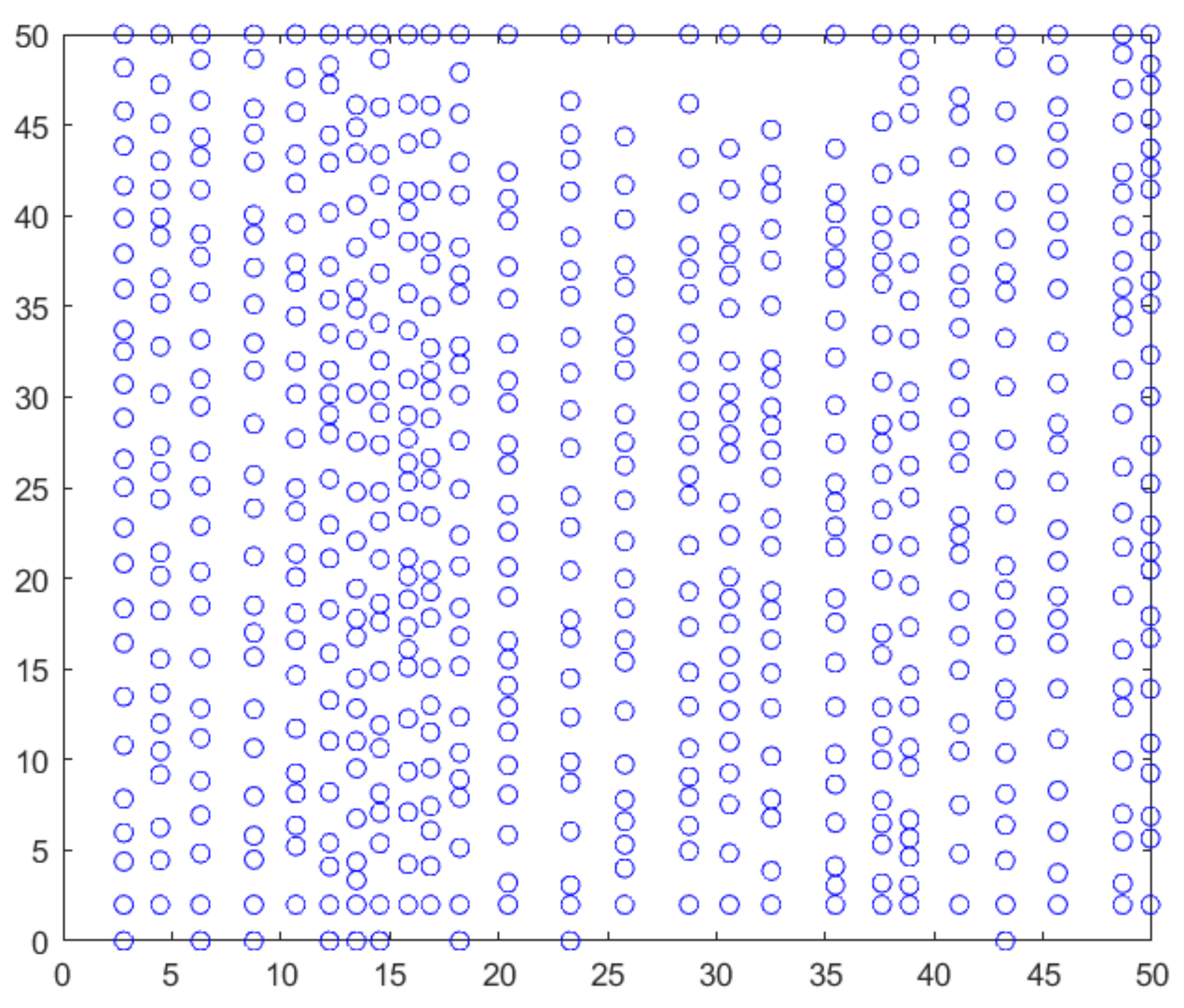
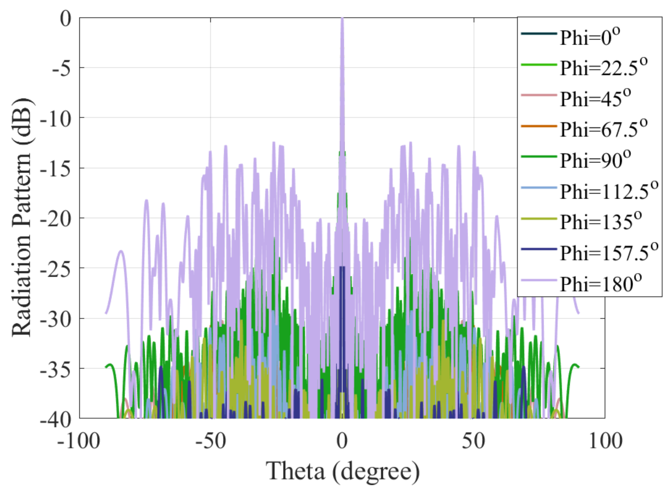
We apply our approach to a planar array with a main beam width of 1 . The aperture of the array is 50.5 λ × 50.5 λ . The main radiation direction is at 0 . The average inter-element distance is 2 λ . Based on the given requirements, the number of elements of a regular array with the same average inter-element distance is 625. The element pattern is a Gaussian pattern with a full width at half maximum (FWHM) of 75 . Pseudo-random optimization is performed in the first step according to (4) and (5). The standard deviation δ is selected to be 1 3 here. The minimum inter-element distance is λ . The angle sampling interval is 0.1 ° . The pseudo-random array distribution is shown in Figure 2. The inter-element distance is calculated from the coordinate of the center of the circle in the array plane. The value of the coordinate in the plane represents the times of the wavelength λ . Radiation patterns in eight planes ( 0 180 with 22.5 ° as increment) are calculated. Different colors represent radiation patterns in different planes. In the figures of radiation patterns, some radiation patterns are covered due to the overlapping of different curves. Figure 3 shows the different radiation patterns obtained from this step by pseudo-random optimization. Because the periodicity of the array is avoided, the grating lobes are suppressed. PSLL is only 12.7 dB. Compared to regular arrays, the suppression of grating lobes is an advantage, albeit at the cost of relatively higher SLL. Therefore, more optimization is needed in order to suppress SLL to the desired value.
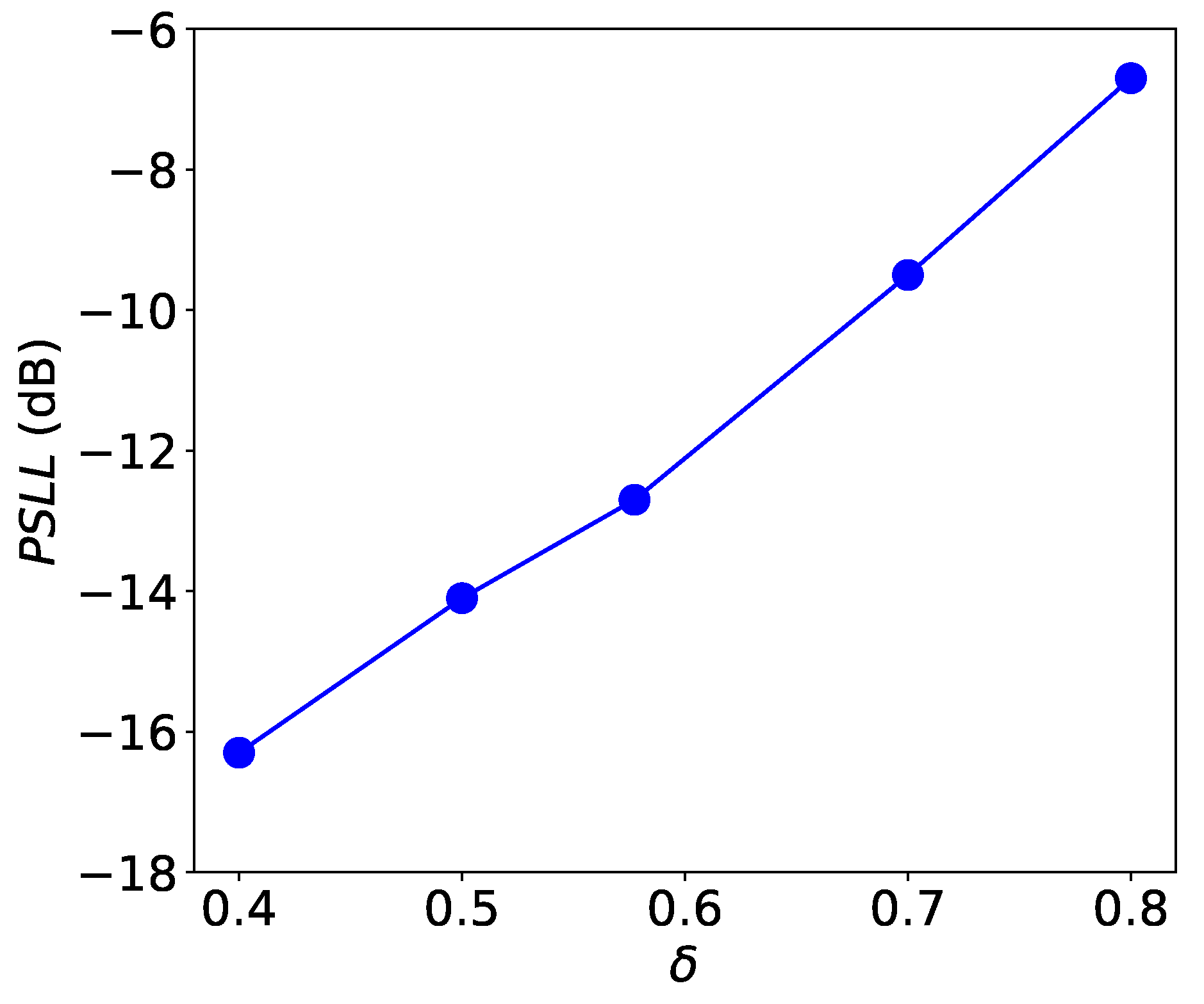
In order to investigate the influence of the value of standard deviation δ on the radiation of the sparse array, we applied another four values in the algorithm. Figure 4 presents the results of PSLL when using different δ values. As we can see, the larger δ results in higher PSLL in the radiation pattern. The larger the standard deviation is, the more sparsity exists in the distribution. More sparsity leads to a reduction in the ability to control side lobes. Then, higher PSLL is achieved in the radiation pattern.
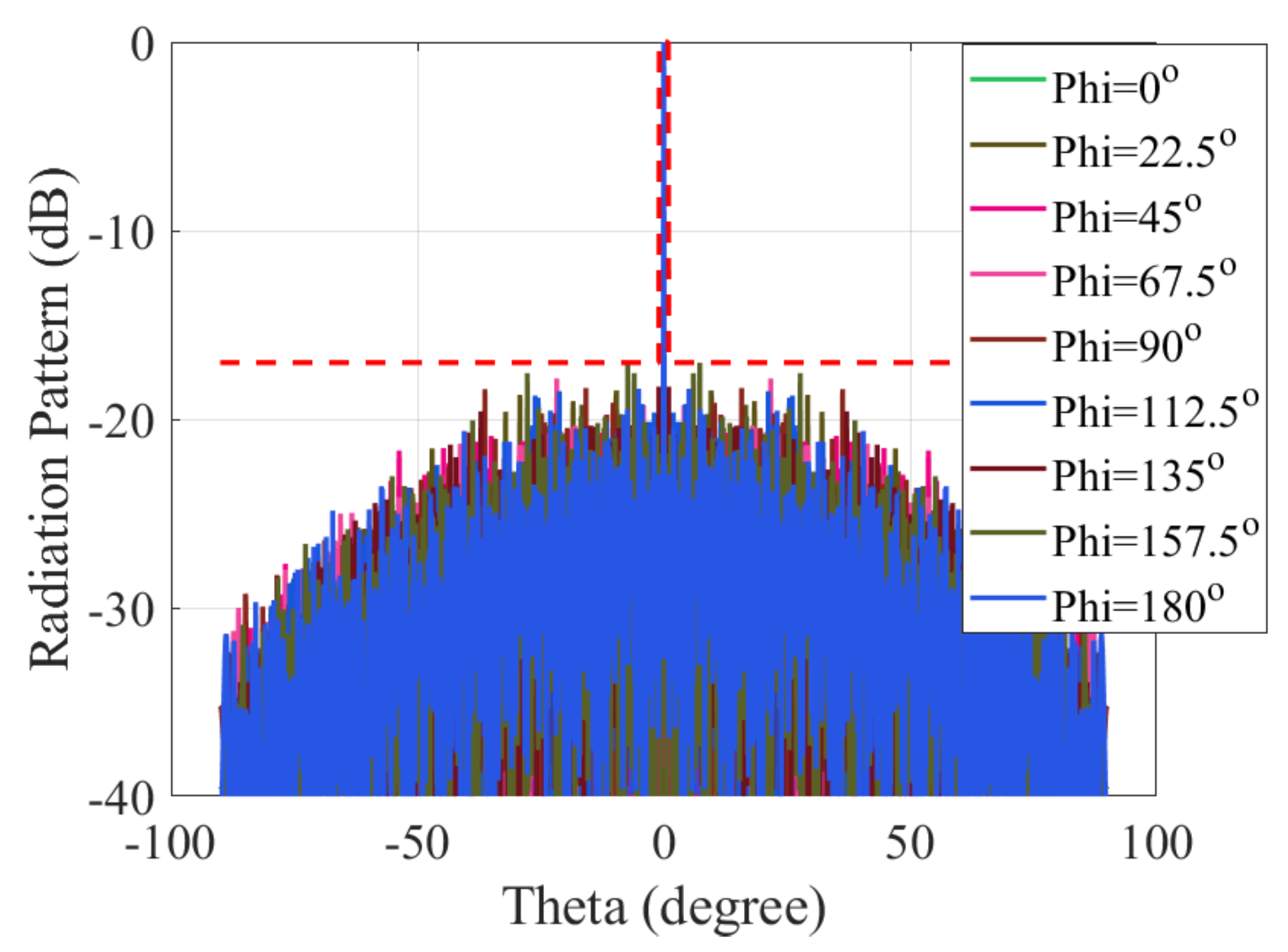
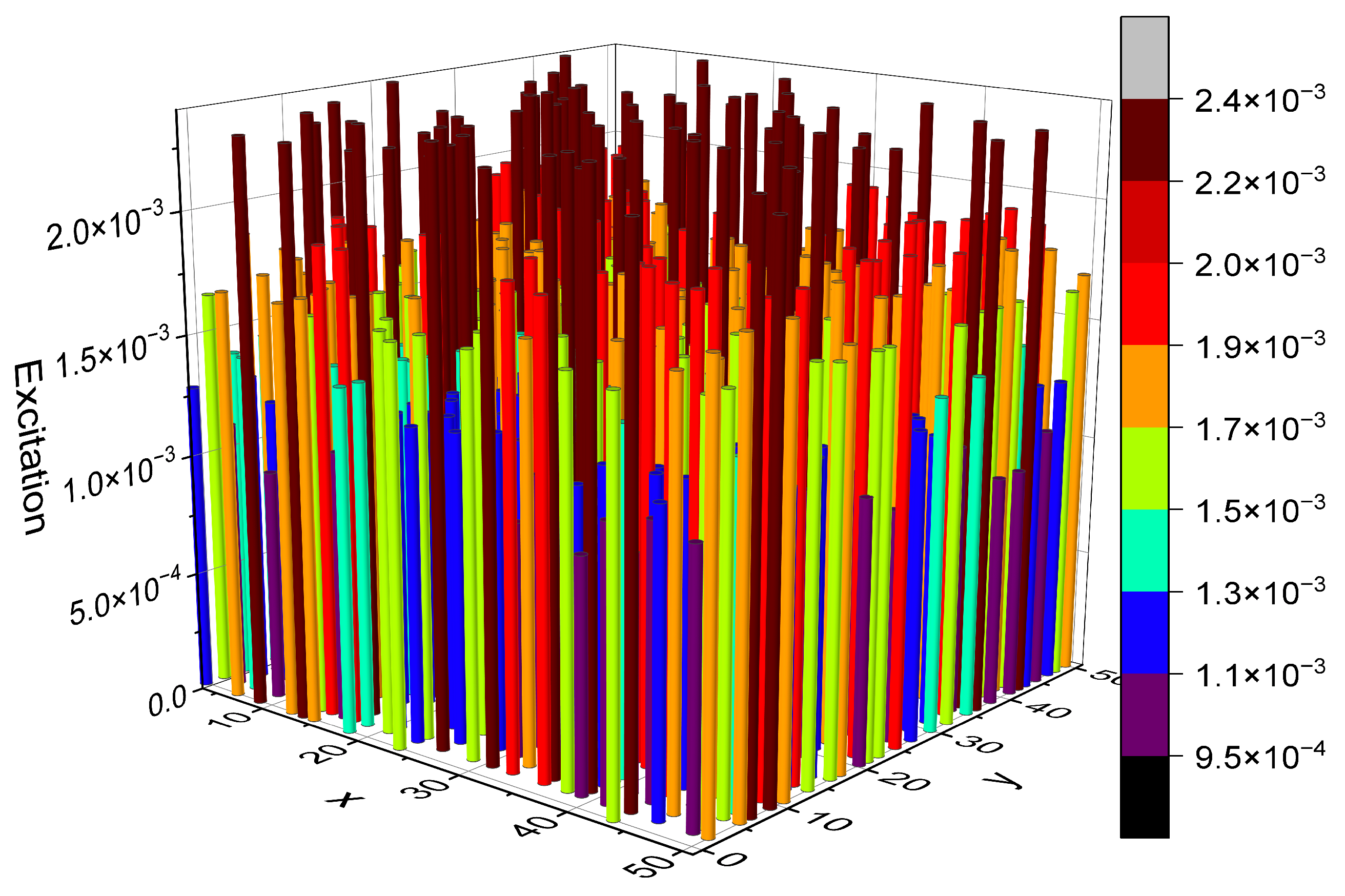
In the second step, convex optimization is utilized to optimize the excitations of the elements in the next step, in order to suppress the SLL. Here, convex optimization is still based on the results obtained with the δ = 1 3 value in the last step. The optimization of the excitations of these elements is operated with the SDPT3 solver in convex under the constraint of the radiation pattern. Finally, the excitations of these elements are obtained with the optimal value combination. Figure 5 presents the radiation patterns optimized by the proposed hybrid algorithm. PSLL is obtained under the constraint of a mask level of 17 dB. Compared to the 12.7 dB PSLL achieved by pseudo-random distribution in the first step, PSLL can be suppressed by 4.3 dB more. The hybrid algorithm has a better optimization performance on the suppression of side lobes. The excitation of each element in each position in this sparse array plane is shown in Figure 6.
The SDPT3 solver used for the optimization utilizes an infeasible path-following algorithm [30] to ensure efficient convergence to an optimal solution by maintaining a balance between primal and dual feasibility while minimizing the duality gap. The convergence process is tracked using three key indicators: primal infeasibility, dual infeasibility and the duality gap, with convergence criteria being max (primal infeasibility, dual infeasibility, duality gap) less than 1.5 × 10 8 to guarantee accuracy. The change of those indication during the optimization process is shown in Figure 7. This figure shows that the convergence criteria are met after 31 iterations.
The iterative process results in a small duality gap of 1.3 × 10 8 , and the relative primal and dual infeasibilities are 2.4 × 10 12 and 1.6 × 10 12 , respectively, indicating a relatively accurate solution. Running on an eight-core computer with 32 GB of memory, the SPDT solver achieved convergence in approximately 12 min.
The computational complexity of solving convex optimization problems in SDPT3 depends on both the number of variables n v and the number of constraints n c . In our specific setup, the problem formulation includes M × N ( M = N = 25 ) variables. The number of constraints depends on the tested elevation angle θ which has a range from 90 to 90 with an interval of 0.1 ° , yielding 1800 different values, and the azimuthal angle ϕ which is tested for 8 different values, so the number of constraints is n c = 1800 × 8 .
Computational complexity includes time complexity and spacial complexity. Using “O” to denote the upper bound, the time complexity per interior-point iteration in SDPT3 is O ( n c 3 ) for dense matrix problems [30,31] due to the operation in checking feasibility. In our problem, SDPT3 requires about 31 iterations to converge, and the computational load is manageable. The space complexity is related to the storage of variables and constraints. Since SPDT3 is a primal-dual barrier method [31], the spacial complexity is O ( n v 2 + n c 2 ) .

4.2. Beam Steering

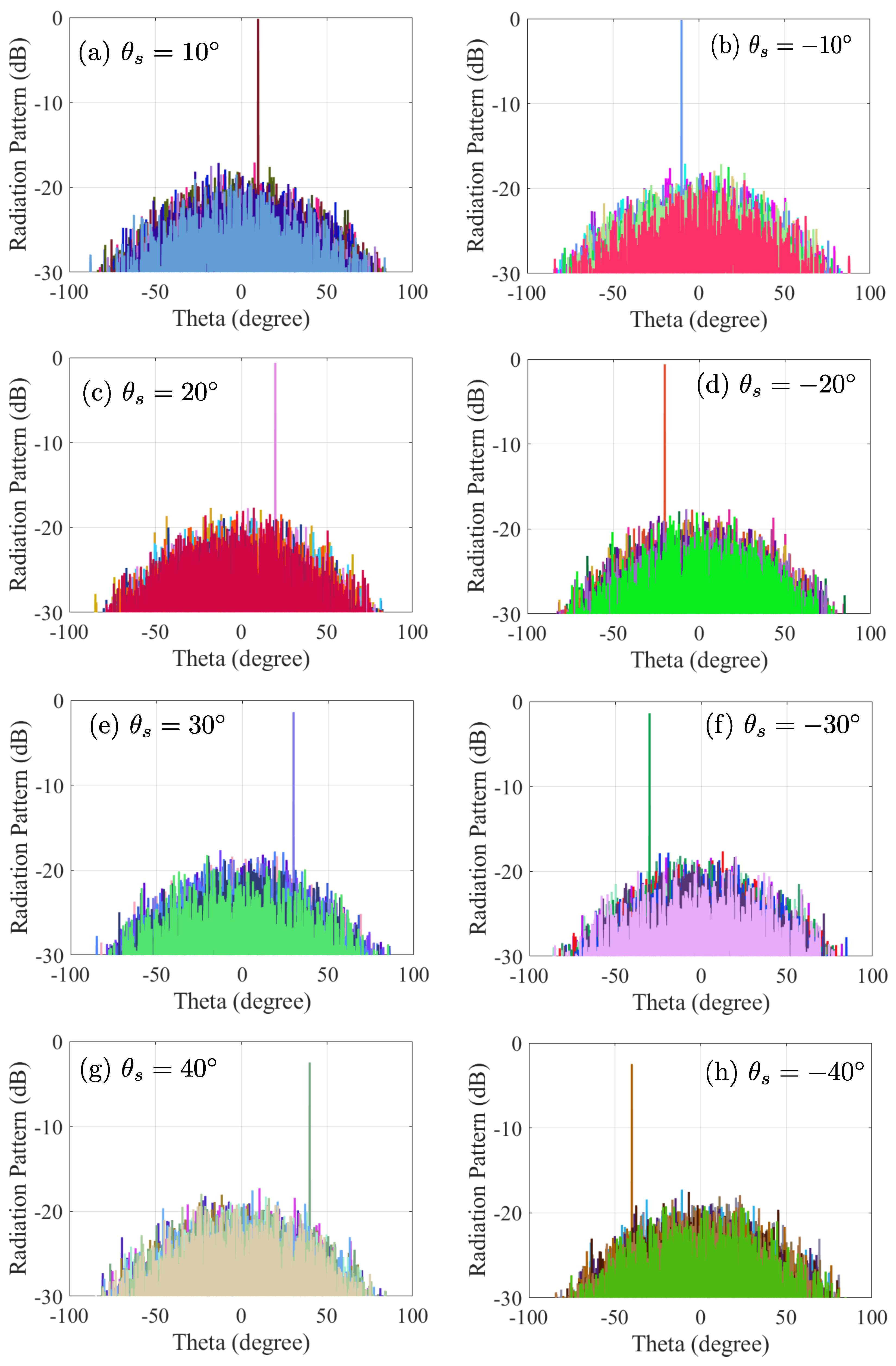
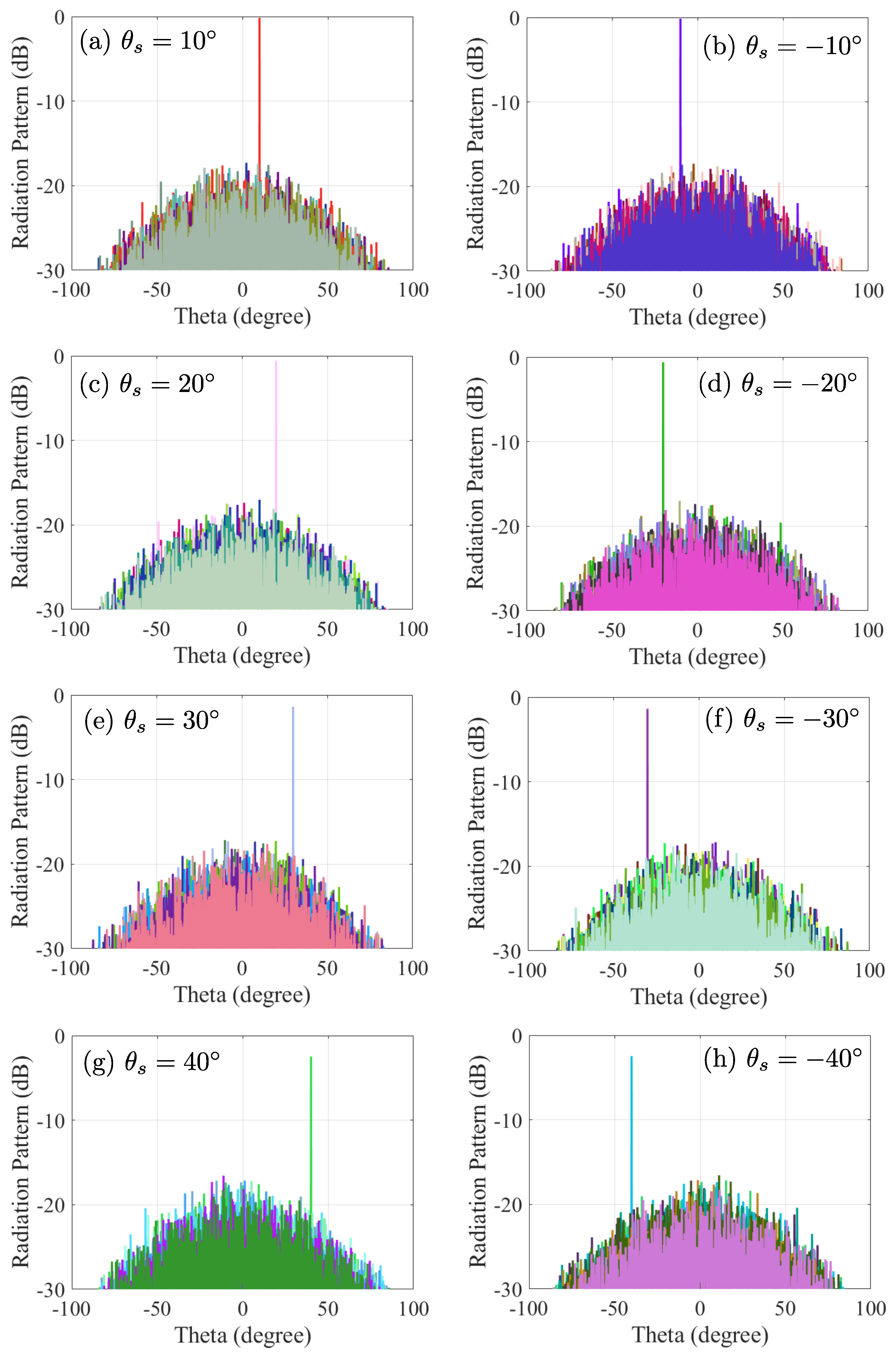
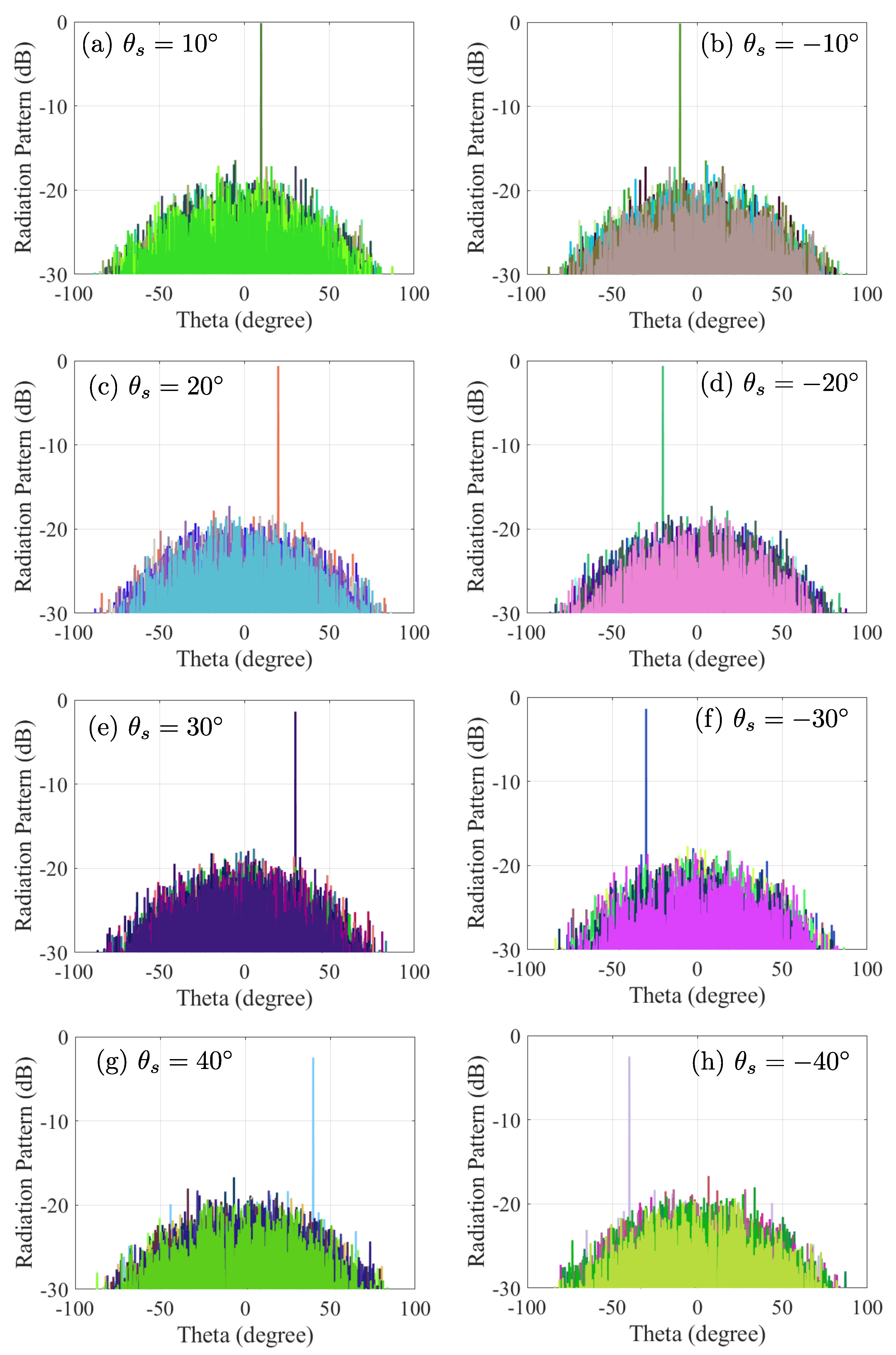
In the previous subsection, it was shown how the pseudo-random optimization can generate a sparse array with no grating lobes and a main beam pointing at broadside. Then, convex optimization was operated in order to decrease the number of elements and SLL. Based on the configuration obtained at the broadside pattern after the two optimization processes, beam steering is operated towards other directions by adding different phase related to these directions. The radiation patterns when steering towards 10 , 10 , 20 , 20 , 30 , 30 , 40 , and 40 in the H, D, and E plane are presented in Figure 8, Figure 9 and Figure 10, respectively.
Compared with some traditional sparse array design methods, this method has several advantages. Firstly, the traditional methods, such as particle swarm algorithm in [21] and genetic algorithm in [24], always focus on the antenna arrays where the inter-element distance is not beyond half wavelength. According to antenna theory, when the inter-element distance is not beyond half wavelength, there is no grating lobe in the radiation pattern. Thus, the main function of these designs is to reduce the number of elements in the array plane, in order to obtain a sparse array. It is worth noting that, when the inter-element distance is beyond half wavelength, the appearance of grating lobes prevents these methods from finding an effective approach to solve the problem. However, the design method in our paper can solve this problem with the suppression of both grating lobes and side lobes, making the use of larger-size elements in phased arrays possible. Secondly, in the generation of the sparse array configuration, the pseudo-random algorithm employed in this method requires significantly less computation and time compared to the complex design methods described in references [6,15,22]. Thirdly, compared with the design method using the same minimum inter-element distance in [32], which reports a PSLL of 7.5 dB, the PSLL with our method is suppressed to the lower level of 17 dB. The combination of the pseudo-random and convex optimization provides more flexibility in the suppression of both grating lobes and SLL, due to the optimization on two aspects (array configuration and element excitations). In addition, beam steering can be achieved with this design method within a large field of view ( 80 ).

5. Conclusions

In conclusion, a hybrid optimization algorithm utilizing pseudo-random and convex optimization is proposed to suppress the grating lobes and side lobes of a sparse array. In this algorithm, pseudo-random optimization is applied to distribute the positions of elements, and convex optimization is applied to optimize the excitations of array elements. The results illustrate that PSLL can be suppressed to 17 dB for a planar array with a main beam width of 1 and a minimum inter-element distance of one wavelength. In addition, beam steering can be achieved within an 80 field of view range. This provides an approach for the suppression of grating lobes and the reduction of SLL with large inter-element distance. Compared with the traditional design methods, this method has several advantages: it provides a solution for sparse array design with inter-element distance larger than half wavelength; it requires less computation and time in the array configuration generation; and a better radiation pattern can be obtained with the same inter-element distance because it offers more flexibility in the suppression of both grating lobes and SLL, due to the combination of two optimizations. In addition, wide beam steering is a further advantage of this design. This hybrid optimization algorithm proves to be an effective and capable solution for sparse array design.

Author Contributions

Conceptualization, P.G.; methodology, P.G.; software, P.G. and Z.C.; validation, P.G. and Z.C.; formal analysis, P.G.; investigation, P.G.; resources, P.G.; data curation, P.G. and Z.C.; writing—original draft preparation, P.G.; writing—review and editing, P.G. and Z.C. All authors have read and agreed to the published version of the manuscript.

Funding

China Scholarship Council (No. 201804910788).

Institutional Review Board Statement

Not applicable.

Informed Consent Statement

Not applicable.

Data Availability Statement

Data are available on request from the authors.

Conflicts of Interest

The authors declare no conflicts of interest.

References

  1. Ahmed, S.S.; Schiessl, A.; Schmidt, L.P. A Novel Fully Electronic Active Real-Time Imager Based on a Planar Multistatic Sparse Array. IEEE Trans. Microw. Theory Tech. 2011, 59, 3567–3576. [Google Scholar] [CrossRef]
  2. Abbasi, H. Sparse: A More Modern Sparse Array Library; SciPy: Austin, TX, USA, 2018; pp. 65–68. [Google Scholar] [CrossRef]
  3. Zheng, Z.; Wang, W.Q.; Kong, Y.; Zhang, Y.D. MISC Array: A New Sparse Array Design Achieving Increased Degrees of Freedom and Reduced Mutual Coupling Effect. IEEE Trans. Signal Process. 2019, 67, 1728–1741. [Google Scholar] [CrossRef]
  4. Alnahwi, F.M.; Al-Yasir, Y.I.A.; Sattar, D.; Ali, R.S.; See, C.H.; Abd-Alhameed, R.A. A New Optimization Algorithm Based on the Fungi Kingdom Expansion Behavior for Antenna Applications. Electronics 2021, 10, 2057. [Google Scholar] [CrossRef]
  5. Niccolai, A.; Zich, R.; Beccaria, M.; Pirinoli, P. SNO Based Optimization for Shaped Beam Reflectarray Antennas. In Proceedings of the 2019 13th European Conference on Antennas and Propagation (EuCAP), Krakow, Poland, 31 March–5 April 2019; pp. 1–4. [Google Scholar]
  6. Mo, H.; Tong, Y.; Wang, Y.; Wang, K.; Luo, D.; Li, W. Sparse Non-Uniform Linear Array-Based Propagator Method for Direction of Arrival Estimation. Electronics 2023, 12, 3755. [Google Scholar] [CrossRef]
  7. Alidoustaghdam, H.; Kokkeler, A.; Miao, Y. Sparse Tiled Planar Array: The Shared Multibeam Aperture for Millimeter-Wave Joint Communication and Sensing. Electronics 2023, 12, 3115. [Google Scholar] [CrossRef]
  8. Shi, W.; Li, Y. Novel Sparse Array Design Based on the Maximum Inter-Element Spacing Criterion. IEEE Signal Process. Lett. 2022, 29, 1754–1758. [Google Scholar] [CrossRef]
  9. Ahmed, A.; Zhang, Y.D. Generalized Non-Redundant Sparse Array Designs. IEEE Trans. Signal Process. 2021, 69, 4580–4594. [Google Scholar] [CrossRef]
  10. Hamza, S.A.; Amin, M.G. Hybrid Sparse Array Beamforming Design for General Rank Signal Models. IEEE Trans. Signal Process. 2019, 67, 6215–6226. [Google Scholar] [CrossRef]
  11. Vigano, M.; Toso, G.; Angeletti, P.; Lager, I.; Yarovoy, A.; Caratelli, D. Sparse antenna array for earth-coverage satellite applications. In Proceedings of the 4th European Conference on Antennas and Propagation—EuCAP, Barcelona, Spain, 12–16 April 2010; pp. 1–4. [Google Scholar]
  12. Chiao, R.; Thomas, L.; Silverstein, S. Sparse array imaging with spatially-encoded transmits. In Proceedings of the 1997 IEEE Ultrasonics Symposium Proceedings, An International Symposium (Cat. No.97CH36118), Toronto, ON, Canada, 5–8 October 1997; Volume 2, pp. 1679–1682. [Google Scholar] [CrossRef]
  13. Bucci, O.M.; Isernia, T.; Perna, S.; Pinchera, D. Isophoric Sparse Arrays Ensuring Global Coverage in Satellite Communications. IEEE Trans. Antennas Propag. 2014, 62, 1607–1618. [Google Scholar] [CrossRef]
  14. Ephrat, P.; Keenliside, L.; Seabrook, A.; Prato, F.S.; Carson, J.J.L. Three-dimensional photoacoustic imaging by sparse-array detection and iterative image reconstruction. J. Biomed. Opt. 2008, 13, 054052. [Google Scholar] [CrossRef]
  15. Wang, X.; Hassanien, A.; Amin, M.G. Dual-Function MIMO Radar Communications System Design via Sparse Array Optimization. IEEE Trans. Aerosp. Electron. Syst. 2019, 55, 1213–1226. [Google Scholar] [CrossRef]
  16. Athley, F.; Engdahl, C.; Sunnergren, P. On radar detection and direction finding using sparse arrays. IEEE Trans. Aerosp. Electron. Syst. 2007, 43, 1319–1333. [Google Scholar] [CrossRef]
  17. Beni, A.; Miccinesi, L.; Pieraccini, M. Comparison between Compressive Sensing and Non-Uniform Array for a MIMO GBSAR with Elevation Resolution: Simulations and Experimental Tests. Electronics 2023, 12, 1100. [Google Scholar] [CrossRef]
  18. Shao, W.; Hu, J.; Ji, Y.; Zhang, W.; Fang, G. W-Band FMCW MIMO System for 3-D Imaging Based on Sparse Array. Electronics 2024, 13, 369. [Google Scholar] [CrossRef]
  19. Liang, C.; Wang, Y.; Yang, Z.; Hu, X.; Pei, Q.; Gu, W.; Zhang, L. Cooperative Automotive Radars with Multi-Aperture Multiplexing MIMO Sparse Array Design. Electronics 2022, 11, 1198. [Google Scholar] [CrossRef]
  20. Wei, S.J.; Zhang, X.L.; Shi, J.; Liao, K.F. Sparse array microwave 3-D imaging: Compressed sensing recovery and experimental study. Prog. Electromagn. Res. 2013, 135, 161–181. [Google Scholar] [CrossRef]
  21. Nipanikar, S.; Hima Deepthi, V.; Kulkarni, N. A sparse representation based image steganography using Particle Swarm Optimization and wavelet transform. Alex. Eng. J. 2018, 57, 2343–2356. [Google Scholar] [CrossRef]
  22. Zhang, H.; Bai, B.; Zheng, J.; Zhou, Y. Optimal Design of Sparse Array for Ultrasonic Total Focusing Method by Binary Particle Swarm Optimization. IEEE Access 2020, 8, 111945–111953. [Google Scholar] [CrossRef]
  23. Chen, K.; Yun, X.; He, Z.; Han, C. Synthesis of Sparse Planar Arrays Using Modified Real Genetic Algorithm. IEEE Trans. Antennas Propag. 2007, 55, 1067–1073. [Google Scholar] [CrossRef]
  24. Ares-Pena, F.; Rodriguez-Gonzalez, J.; Villanueva-Lopez, E.; Rengarajan, S. Genetic algorithms in the design and optimization of antenna array patterns. IEEE Trans. Antennas Propag. 1999, 47, 506–510. [Google Scholar] [CrossRef]
  25. Enache, F.; Deparateanu, D.; Enache, A.; Popescu, F. Sparse array antenna design based on dolph-chebyshev and genetic algorithms. In Proceedings of the 2016 8th International Conference on Electronics, Computers and Artificial Intelligence (ECAI), Ploiesti, Romania, 30 June–2 July 2016; pp. 1–4. [Google Scholar] [CrossRef]
  26. Fuchs, B. Synthesis of Sparse Arrays with Focused or Shaped Beampattern via Sequential Convex Optimizations. IEEE Trans. Antennas Propag. 2012, 60, 3499–3503. [Google Scholar] [CrossRef]
  27. Hong, T.; Shi, X.P.; Liang, X.S. Synthesis of Sparse Linear Array for Directional Modulation via Convex Optimization. IEEE Trans. Antennas Propag. 2018, 66, 3959–3972. [Google Scholar] [CrossRef]
  28. Sayyah, K.; Efimov, O.; Patterson, P.; Schaffner, J.; White, C.; Seurin, J.F.; Xu, G.; Miglo, A. Two-dimensional pseudo-random optical phased array based on tandem optical injection locking of vertical cavity surface emitting lasers. Opt. Express 2015, 23, 19405. [Google Scholar] [CrossRef] [PubMed]
  29. Boyd, S.; Vandenberghe, L. Convex Optimization; Cambridge University Press: Cambridge, UK, 2004. [Google Scholar]
  30. Tütüncü, R.H.; Toh, K.C.; Todd, M.J. Solving semidefinite-quadratic-linear programs using SDPT3. Math. Program. 2003, 95, 189–217. [Google Scholar] [CrossRef]
  31. Borchers, B.; Young, J.G. Implementation of a primal–dual method for SDP on a shared memory parallel architecture. Comput. Optim. Appl. 2007, 37, 355–369. [Google Scholar] [CrossRef]
  32. Aldaya, I.; Dias, B.; Santos, M.P.; De Oliveira, J.A.; Abbade, M.L.F.; Penchel, R.A. Optimization of mean inter-element distance in aperiodic sparse linear phased array antennas. In Proceedings of the 2022 IEEE International Symposium on Antennas and Propagation and USNC-URSI Radio Science Meeting (AP-S/URSI), Denver, CO, USA, 10–15 July 2022; pp. 1276–1277. [Google Scholar] [CrossRef]
Figure 1. Procedure of the proposed algorithm.
Electronics 13 04422 g001
Figure 2. Element distribution of the sparse array by the pseudo-random optimization.
Electronics 13 04422 g002
Figure 3. Radiation pattern optimized by the pseudo-random optimization.
Electronics 13 04422 g003
Figure 4. PSLLs in the radiation pattern of the sparse array using different δ values in the pseudo-random algorithm.
Electronics 13 04422 g004
Figure 5. Radiation pattern optimized by the proposed hybrid optimization.
Electronics 13 04422 g005
Figure 6. Excitation of each element in the sparse array by the proposed hybrid optimization.
Electronics 13 04422 g006
Figure 7. The values of primal infeasibility, dual infeasibility and the duality gap at each iterative steps during the optimization process.
Electronics 13 04422 g007
Figure 8. Radiation pattern in the H plane when the steering angle is (a) 10 ; (b) 10 ; (c) 20 ; (d) 20 ; (e) 30 ; (f) 30 ; (g) 40 ; and (h) 40 .
Electronics 13 04422 g008
Figure 9. Radiation pattern in the D plane when the steering angle is (a) 10 ; (b) 10 ; (c) 20 ; (d) 20 ; (e) 30 ; (f) 30 ; (g) 40 ; and (h) 40 .
Electronics 13 04422 g009
Figure 10. Radiation pattern in the E plane when the steering angle is (a) 10 ; (b) 10 ; (c) 20 ; (d) 20 ; (e) 30 ; (f) 30 ; (g) 40 ; and (h) 40 .
Electronics 13 04422 g010
Disclaimer/Publisher’s Note: The statements, opinions and data contained in all publications are solely those of the individual author(s) and contributor(s) and not of MDPI and/or the editor(s). MDPI and/or the editor(s) disclaim responsibility for any injury to people or property resulting from any ideas, methods, instructions or products referred to in the content.