Abstract
In the dental prosthetics field, BLDC micro-motors are primarily used for implant procedures. As dental materials become increasingly harder, there is a growing demand for higher performance motors to precisely process these materials. However, difficulties in motor development arise due to price competitiveness. Dental motors require capabilities such as low-speed, high-torque for drilling operations and high-speed rotation for precise machining of high-strength dental materials. Additionally, there is a requirement to address thermal issues to prevent user burns due to motor-generated heat. Typically, motors requiring precision control utilize high-resolution position sensors like encoders or resolvers to acquire and control the rotor’s position. However, the high cost of these sensors and constraints such as increased device size pose challenges in maintaining price competitiveness. In this paper, we propose a control algorithm that satisfies the requirements for low-speed, high-torque and high-speed operation requirements for precision machining without hardware modifications using a BLDC micro-motor equipped with an inexpensive Hall sensor commonly used in the dental field. Furthermore, the algorithm is designed to ensure stable operation even in the event of Hall sensor failure or malfunction, and its effectiveness is validated through experiments.
1. Introduction
In the dental prosthetics field, inexpensive micro-DC motors have been used for fabricating dental prostheses. However, advancements in medical technology and dental materials have necessitated the fabrication of more precise and robust prostheses than before. To meet these requirements for machining precision and high-torque performance, handpiece motors have transitioned from DC motors to BLDC motors, and technologies like inverters for motor operation have been employed. Recently, there has been an increasing demand for high-output performance in handpiece motors in the field of dental prosthetics to integrate additional functionalities required for the precision machining of dental materials and implant procedures. To solve this problem, replacing the position sensor of the BLDC motor with expensive sensors such as encoders or resolvers, or adding additional devices such as reduction gears, may lead to problems with price competitiveness due to increased costs. In high-cost position sensor-based Field Oriented Control (FOC) algorithms, extensive computations are required to output sinusoidal currents, including dead-time operations and coordinate transformations. High-speed operation of medical micro-motors is utilized for precision machining at low torque and high rotation speeds, requiring a strategy focused on stable high-speed performance rather than maintaining constant torque. On the other hand, when using Hall sensors and conventional BLDC controllers instead of expensive sensors, various issues arise, such as degraded control performance at low speeds with high torque and heating problems due to temperature saturation during high-speed operation. To overcome the control challenges in extreme conditions such as ultra-high-speed operation, algorithms are required to be developed that enable rapid transition to an enhanced control mode in the frequently encountered low-speed, high-torque and high-speed ranges of handpiece micro-motors. This will enable the development of optimized control technologies suitable for precision ultra-high-speed motors, such as those used in the field of dental prosthetics. Furthermore, in dental handpiece applications, most research focuses on air turbine motors. Although air turbine motors have the advantage of being well suited for high-speed operation, they have limitations in low-speed operation and stable speed control due to the inertia generated by pneumatic pressure [1,2,3].
This paper describes the transition algorithm of the inverter’s motor control method for handpiece motors using low-cost Hall sensors without additional hardware configuration. Firstly, it introduces the limitations and issues of the control methods for handpiece BLDC motors using conventional BLDC motors. Secondly, it proposes algorithms for the low-speed, high-torque region of handpiece BLDC motors for tasks such as tapping for implant placement and for the high-speed, low-torque region required for precision machining. Thirdly, it proposes algorithms for signal processing and compensation-drive techniques using the Hall sensor for ensuring the driving reliability of handpiece motors. Finally, performance tests are conducted by applying the proposed algorithms to handpiece motors using existing Hall sensors. Through the experimental results, it is verified that the proposed method reported in this paper can enhance both low-speed, high-torque and high-speed performance, as well as expands the speed operating range of handpiece motors using low-cost Hall sensors.
2. Problems with Existing Handpiece Micro-BLDC Motors
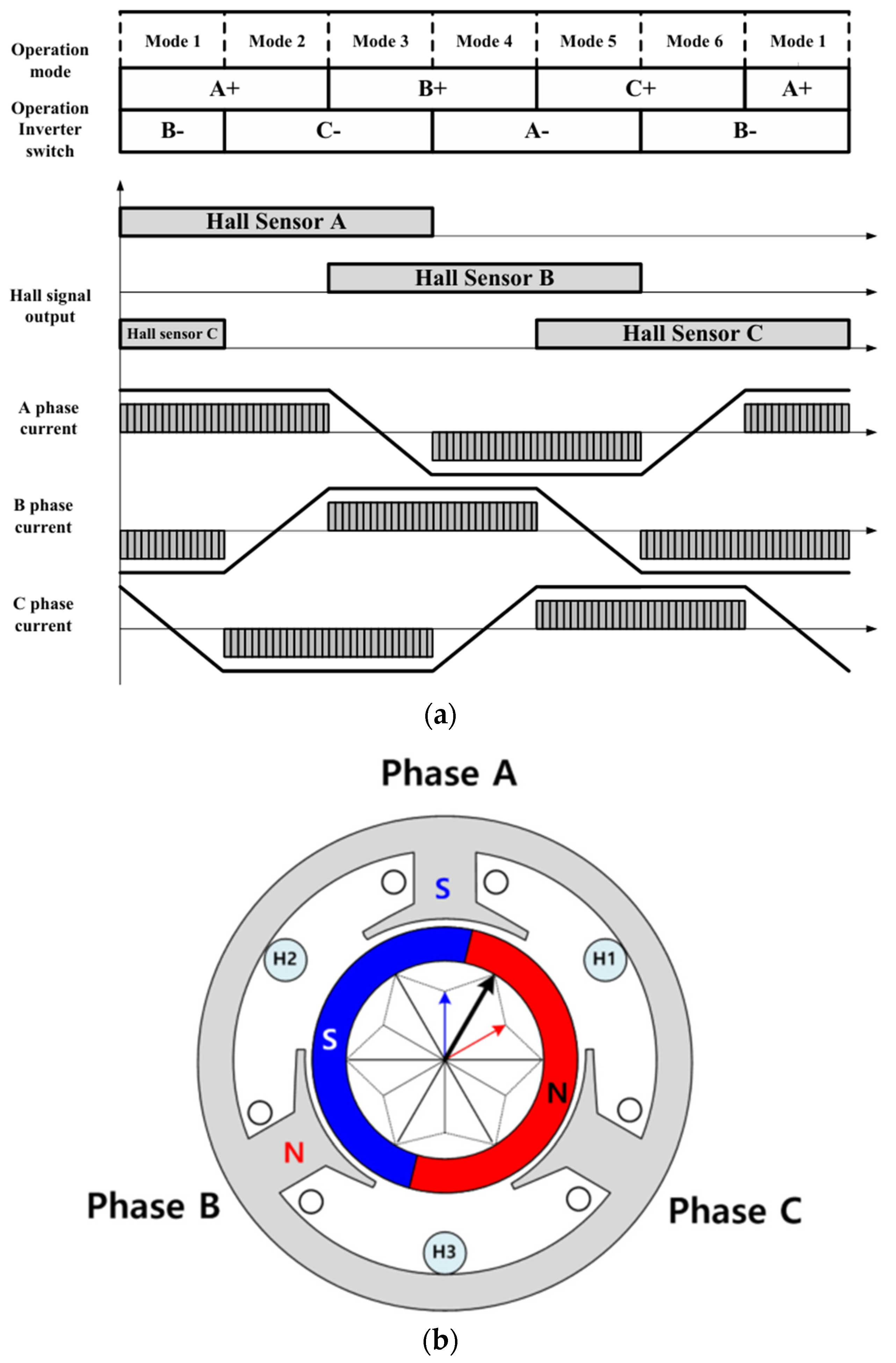
In existing handpiece BLDC motors, the six-step control method is utilized for operation using three Hall sensors as position signals, as depicted in Figure 1a. The six-step control method offers the advantage of simplicity and is advantageous for high-speed operation. However, it has a drawback in low-speed operation due to issues with the low resolution of digital Hall sensors. Consequently, the six-step control results in non-linear motor operation and increased harmonic distortion, which can lead to poor precision in position and speed control at low speeds, as well as increased torque ripple. In particular, for micro-BLDC motors, they are mostly designed to excel in high-speed operation [4,5], often featuring a rotor with a pole count of two, which is conducive to high-speed operation. As depicted in Figure 1b, the micro-BLDC motor used in this study, like typical handpiece micro-motors, also features a two-pole configuration. Consequently, only one cycle of the Hall sensor signal is output per revolution of the motor, which makes low-speed control challenging.

Figure 1.
General driving control method for a BLDC motor: (a) BLDC six-step control method using Hall sensors; (b) configuration of a two-pole BLDC motor using Hall sensors.
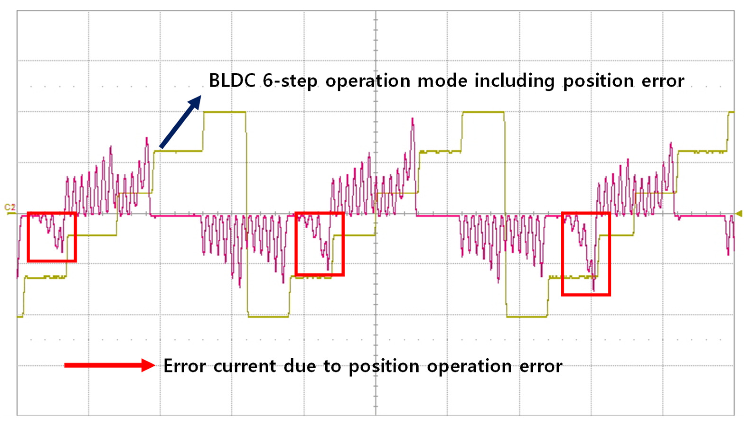
Recently, some handpiece motors have adopted sensorless control techniques to drive the motor by tracking the position of the rotor without using magnetic sensors, aiming to reduce costs and simplify the structure [6,7]. However, micro-motors generally use thin coils as stator windings, and the number of coil turns per stator slot is large, which means they can generate significant heat even with a small current. In the sensorless position control technique based on the parameters of the motor operation area, when a position error occurs due to low accuracy parameters or an external load condition, the input current fluctuates and acts as a load, as shown in Figure 2. The current generated by this error has the disadvantage of generating more heat, as shown in (1), where represents the amount of energy generated due to temperature changes, denotes erroneously commutating current, and is the resistance of the stator coil in the motor.
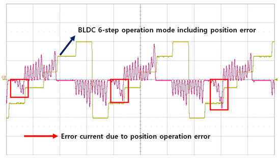
Figure 2.
Incorrect commutating current due to position errors during BLDC motor control.
3. Algorithm for Expanding the Speed Operating Range of Micro-Motors for Handpiece Applications
As previously described, handpiece micro-motors require performance for both low-speed, high-torque operations such as tapping for implant placement and high-speed, low-torque operations required for precision machining. The fundamental idea of this study is an algorithm that expands the speed operation range of the motor without additional hardware modification for low-resolution Hall sensor-type handpiece motors, which is unable to operate at low speeds.
3.1. Low-Speed, High-Torque Control Algorithm for Micro-Motors
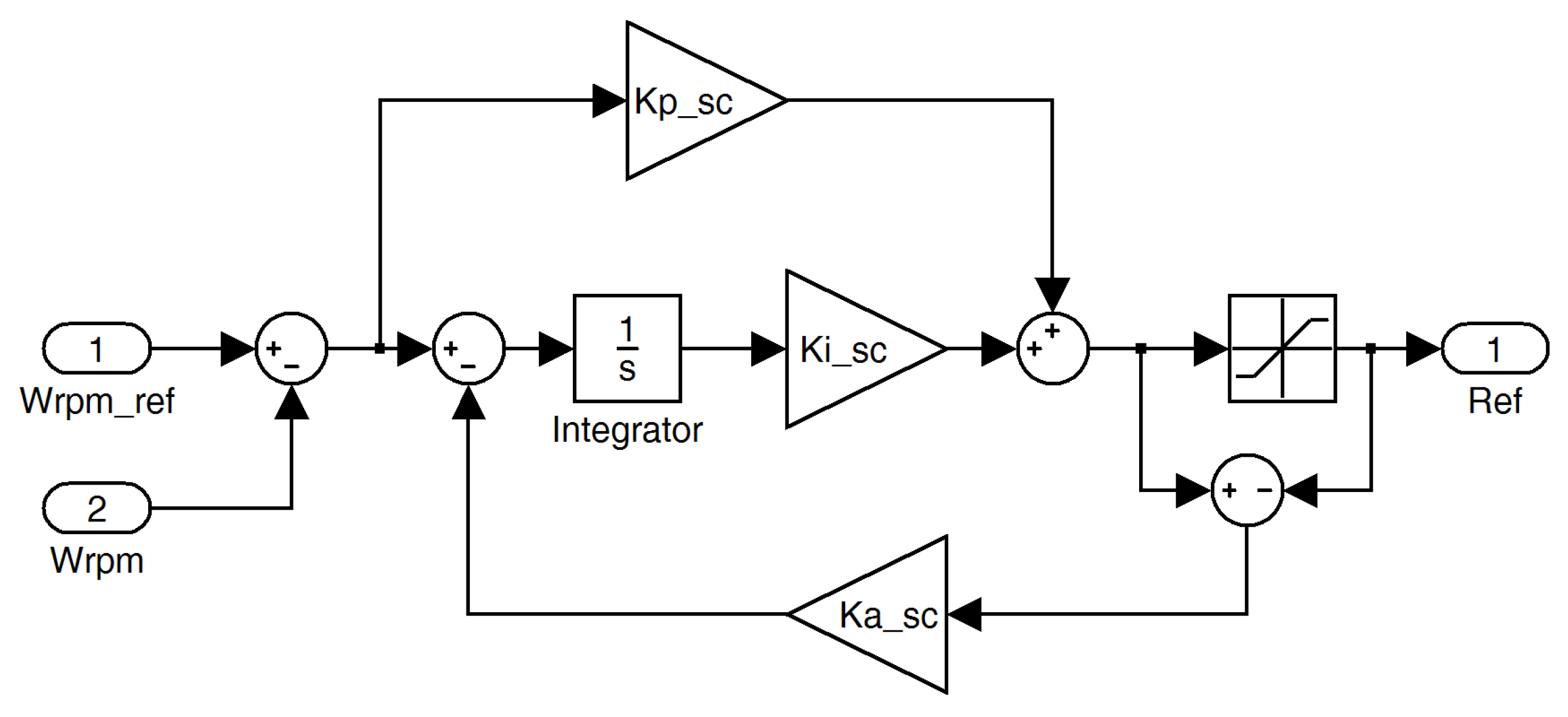
In situations where the low-speed, high-torque output of the motor is required, such as tapping for implant placement, it is essential for the motor to maintain a consistent force without a decrease in speed when subjected to a load. The general speed PID control algorithm for a motor is structured as depicted in Figure 3. The speed control algorithm depicted in Figure 3, which increases the compensation current and speed through the PID controller based on the difference error caused by speed reduction due to load variations, is not suitable.
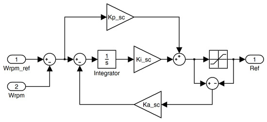
Figure 3.
Speed control diagram with general PID controllers.
In addition, the general six-step control of a BLDC motor generates rotational force by operating in six modes of two-phase switching commutation using a Hall sensor, as shown in Figure 1a and Figure 4. The low-cost Hall sensor of a two-pole handpiece motor provides low-resolution position information, and the six-step control, which generates six operating modes per rotation of the motor, is not suitable for maintaining constant speed and torque output in the low-speed operation range. The six-step control results in non-linear motor operation and increased harmonic distortion, which can lead to poor precision in position and speed control at low speeds, as well as increased torque ripple [8,9]. Therefore, in systems where precise and constant control performance is crucial, more accurate control methods like Field-Oriented Control (FOC) are applied.
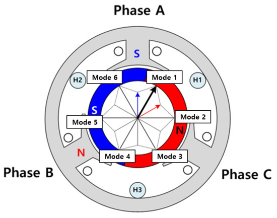
Figure 4.
Six-step control method for a two-phase BLDC motor using a Hall sensor.
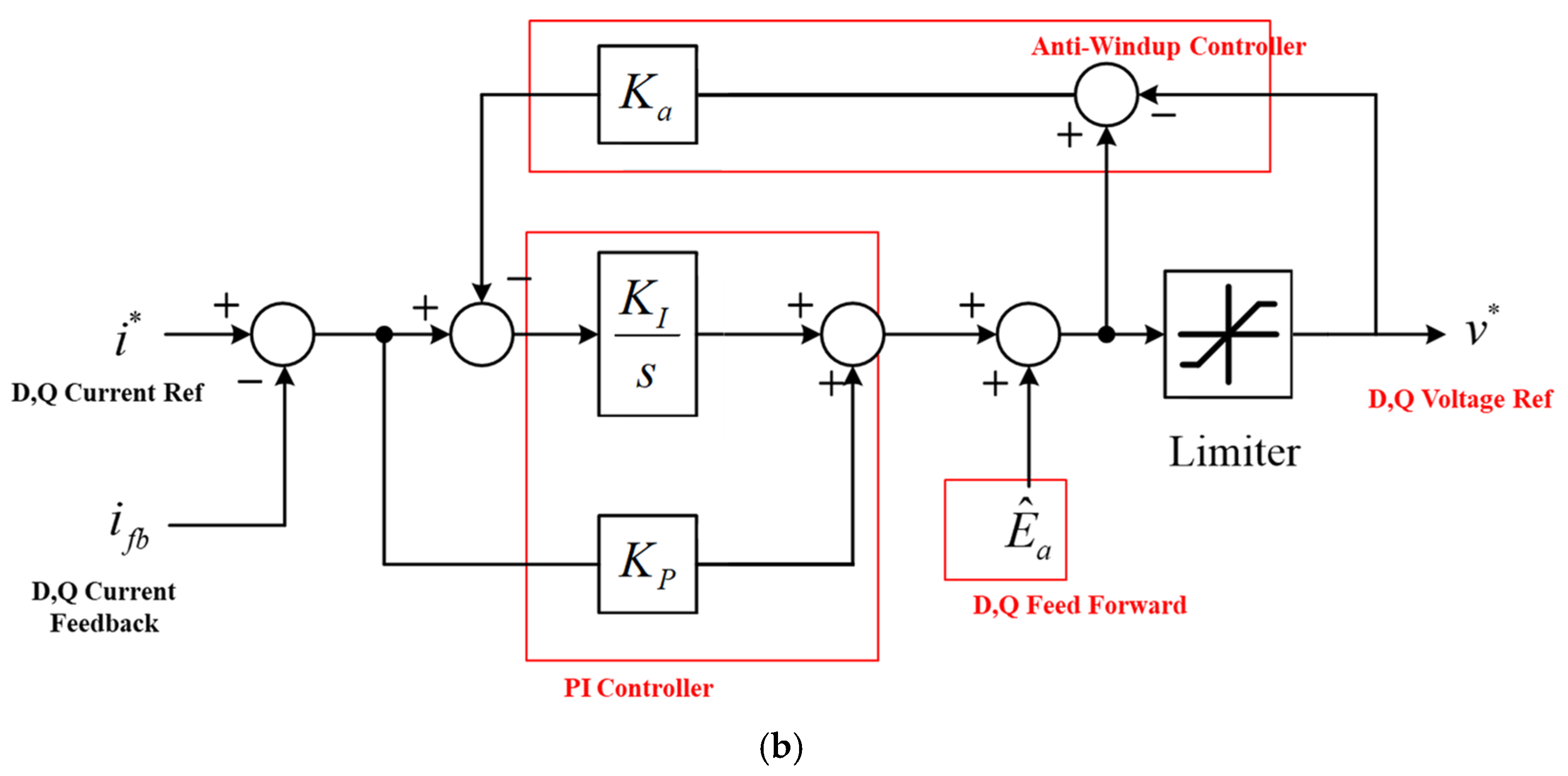
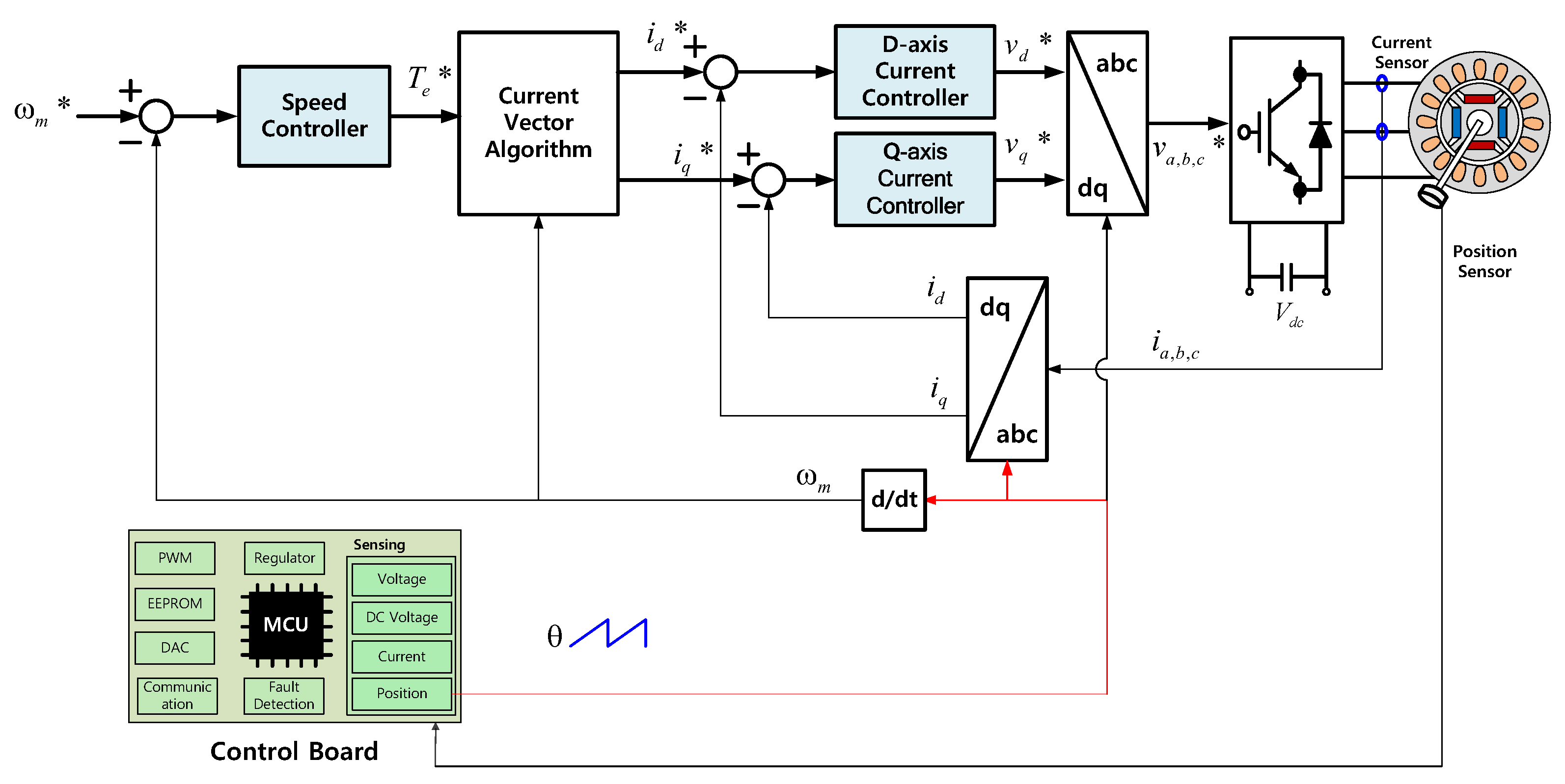
Therefore, in the low-speed operation range of the handpiece motor, the algorithm must be designed to enable drive using a three-phase PWM method through vector control, as shown in Figure 5a, rather than the six-step control. Additionally, as shown in Figure 5b, an algorithm must be designed to produce stable rotational force at a constant speed by adding a current controller that can produce a constant torque.
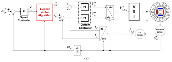

Figure 5.
Block diagrams for constant speed and torque control using the vector control method: (a) speed control; (b) current control for maintaining constant torque.
In order to implement vector control techniques, position information with a high resolution for 360° range is required. However, in the case of a handpiece motor with a two-pole Hall sensor attached, the low number of motor poles and the relatively low resolution of the Hall sensor at low speeds make speed calculation difficult. To acquire high-resolution position information, the techniques such as sensorless parameter estimation methods can be used [10]. However, as previously described, in the case of micro-motors that are sensitive to parameter changes such as temperature, there is a high possibility of position errors [11,12], and due to the characteristics of the dental handpiece micro-motor, which can be frequently exposed to rapid load changes, stable control is difficult.
Therefore, this paper proposes an adaptive low-speed control method by generating a forced 360° position signal according to the number of motor poles using MCU (Micro-Controller Unit) and Hall sensor. The generated rotor position signal is then fed back into speed controller input and current controller for - transformation, as shown in Figure 6.

Figure 6.
Block diagram of the low-speed control method using MCU and Hall sensor.
The relationship between the frequency and speed of a two-pole handpiece motor is represented in (2), where p denotes the number of poles of the magnet, and represents the electric angular frequency applied to the motor.
Using this equation, the electric angular frequency corresponding to any reference speed can be determined, as shown in (3) and (4), and this signal can be converted into to process the rotor position data.
By applying the rotor position signal, processed through (4), into the vector control algorithm, the rotor position of the motor can be synchronized with the stator flux at low speeds, enabling effective control.
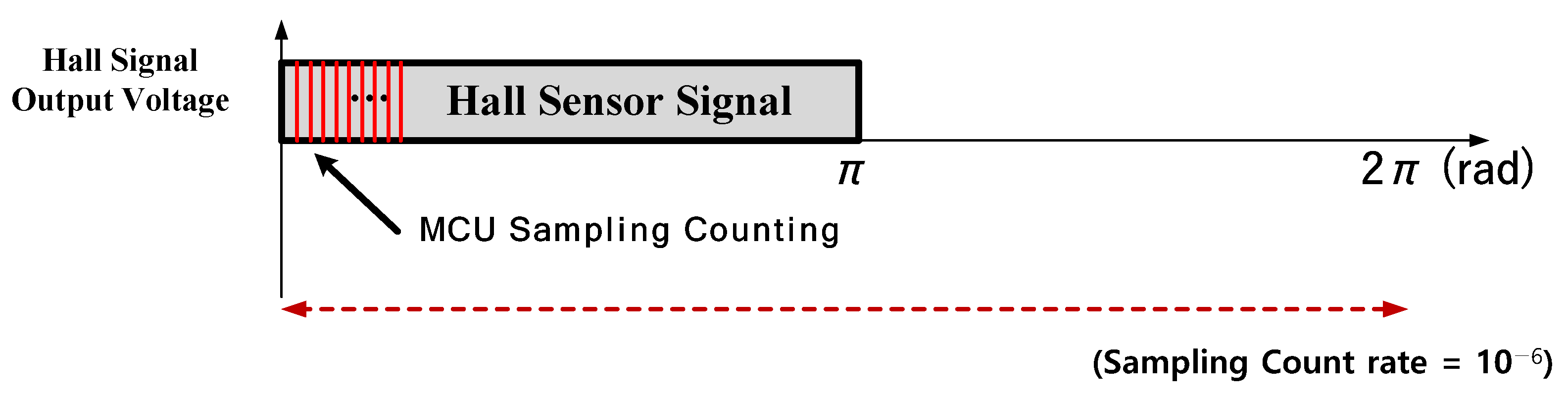
Figure 7 represents the method for converting the binary position signals (0 and 1) from a digital Hall sensor installed to the motor into precise position information, using an MCU with a 10 kHz processing speed. The signal from the digital Hall sensor can be sampled over one electric angle period of to derive the time difference using (5).
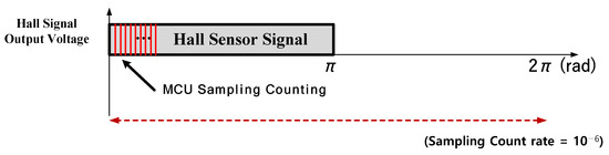
Figure 7.
Processing and control method for the position signal using a Hall sensor.
The method for converting the sampled values from the digital Hall sensor into the rotor position signal is described in (6), where represents the Hall sensor data sampling frequency, and denotes the value of the rotor position signal at the sampling time instance.
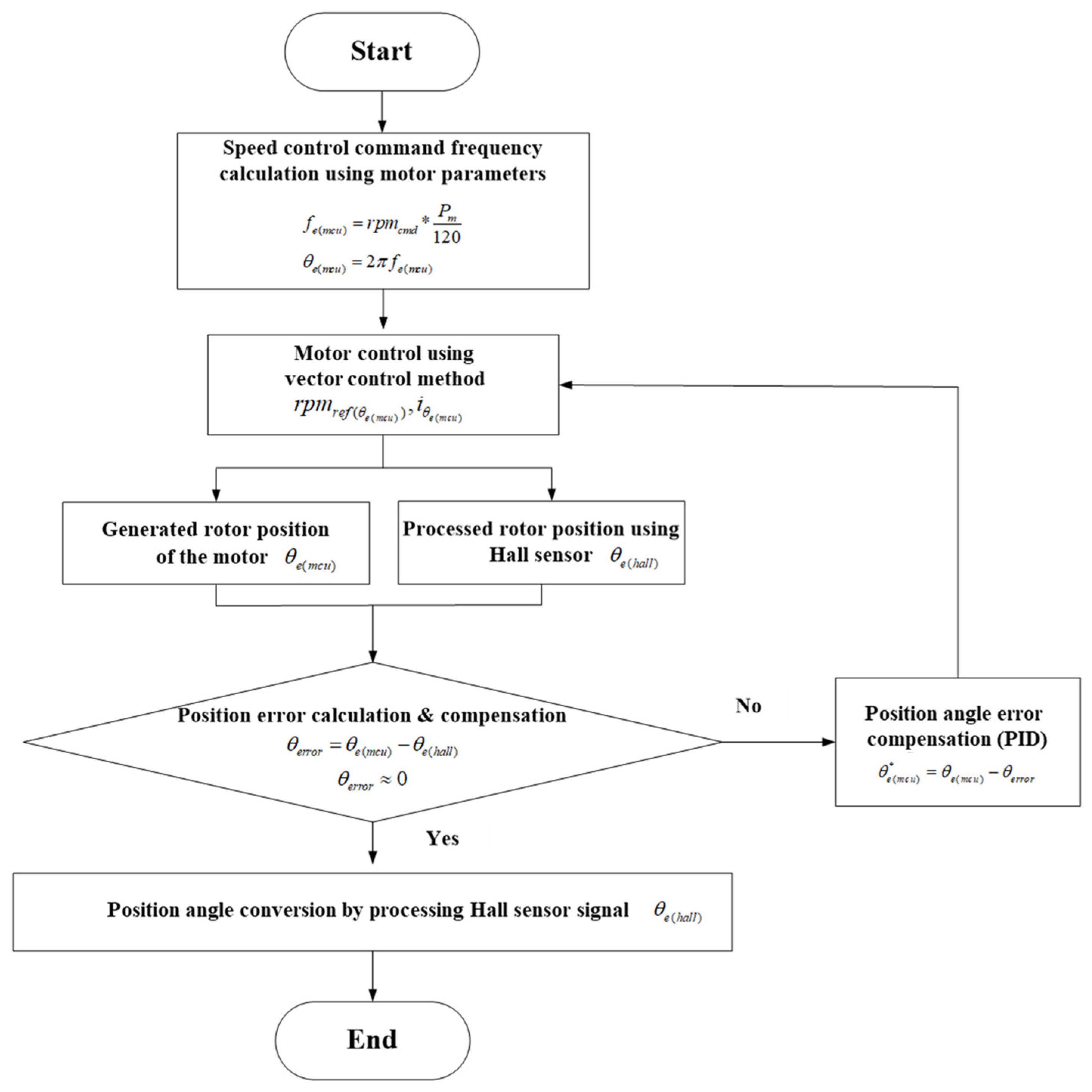
Figure 8 illustrates the flow chart of the transition method for the rotor position signal at a certain high speed, where stable sampling of the Hall sensor is achieved, after driving the motor with forced synchronization at low speeds using (4). First, in the low-speed, high-torque range, stable speed control is performed through vector control based on the obtained from (3) and (4). Next, at speeds where stable sampling of the Hall sensor occurs, the corrected Hall sensor angle is calculated using (5) and (6). Simultaneously, to synchronize the MCU and Hall sensor angles, the angle error is computed using (7). Finally, once the desired speed transition range is reached and the speed transition begins, the position angle error compensation algorithm, based on PID control, is quickly processed to minimize the position angle error (, which allows the motor to operate based on the Hall sensor angle signal.
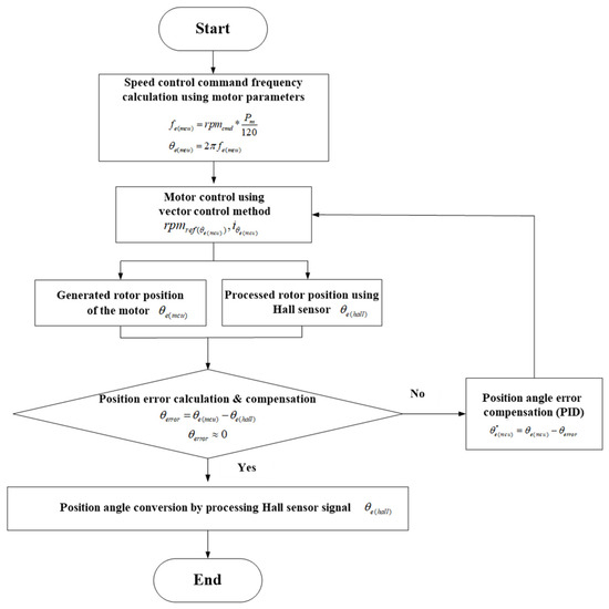
Figure 8.
Transition method for synchronizing the rotor position signal between and .
The relationship shown in (7) represents the error value between the forcibly generated rotor position in (4), through the MCU, and the processed rotor position in (6), obtained by sampling the accurate position information from the Hall sensor attached to the motor.
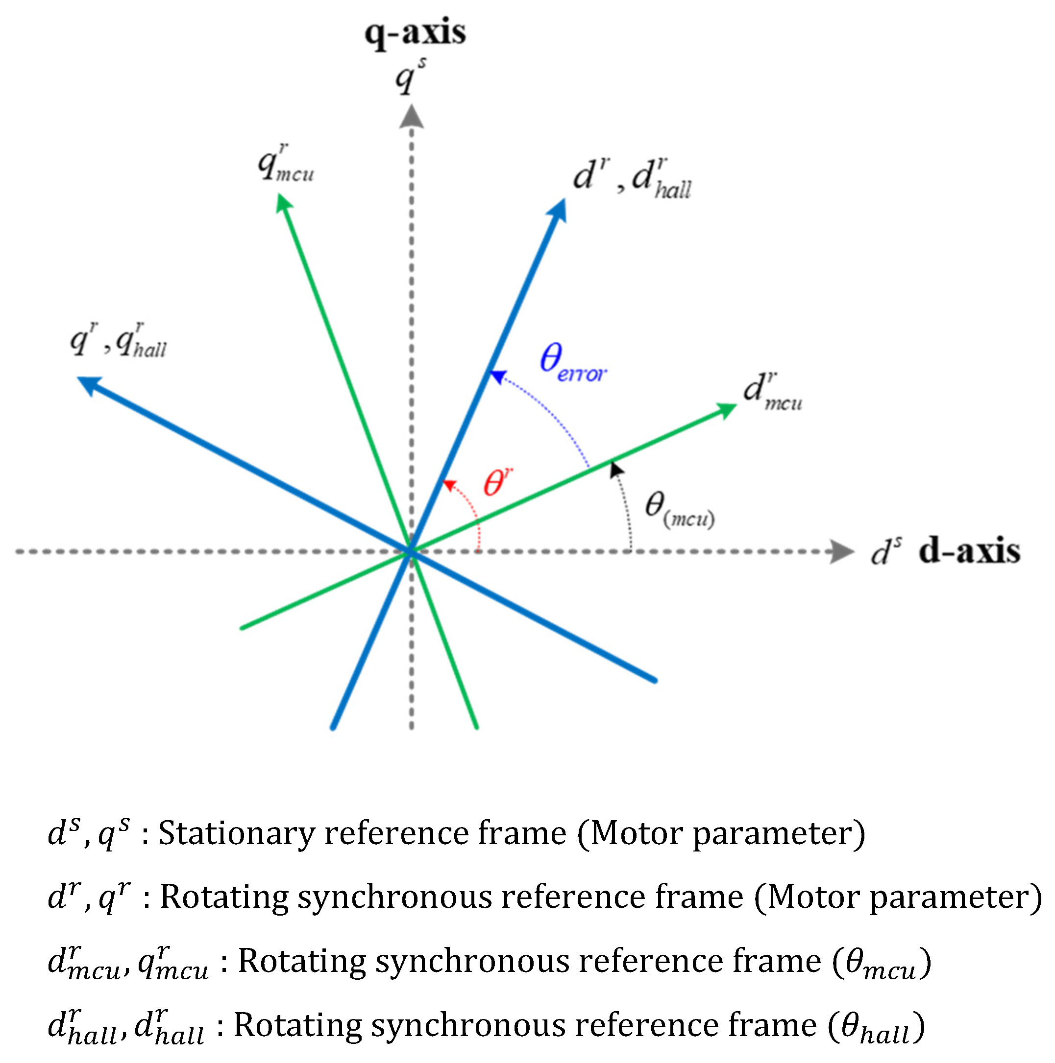
Figure 9 illustrates the relationship between the stationary coordinate system ; the synchronous coordinate system based on the Hall sensor; and the current coordinate system using the generated position information from the MCU. The coordinate system , based on the information from the Hall sensor attached to the motor, is identical to the rotor’s rotational coordinate system .
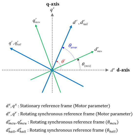
Figure 9.
The relationship between the stationary coordinate system ; the synchronous coordinate system ; and the MCU-generated coordinate system of the handpiece motor.
When performing speed control using the rotor position signal generated by the MCU, the rated current vector is applied, frequently causing the load torque to be smaller than the rated current torque. In these cases, the synchronous coordinate system of the actual rotor rotates with a delay compared to coordinate system shown in Figure 9.
Therefore, the position information must be transitioned after eliminating the position error that occurs between the actual synchronous coordinate system and the generated coordinate system from the MCU . The current reference for the motor, incorporating the generated position signal from (7), can be determined as shown in (8). Generally, the output torque of a permanent magnet synchronous motor is determined by the -axis current, the -axis current in the synchronous coordinate system, and the motor parameters, as given in (9). In addition, the - and -axis currents , derived from generated position information with position errors, are transformed in the synchronous reference frame, as described in (10). Therefore, the output torque equation is expressed as (11) using the generated rotor position information.
For low-speed operation of medical handpiece motors, as previously discussed, it is often impractical to use the signals from Hall sensors attached to the motor in the extremely low-speed operating region required for implant placement. Therefore, a vector control strategy utilizing should be employed for such extremely low-speed operations. In the mid-speed range, where a constant high torque is required for machining rigid prosthetics after the extremely low-speed region, the algorithm should be converted to ensure stable current control based on , which utilizes the signals from the Hall sensors. However, when transitioning the controller position information in the presence of position errors as described in (7), thermal issues of the medical handpiece motor due to motor pulsation or a degradation in control performance may occur, as referred to Figure 2 and (11). Therefore, after reducing the value as shown in Figure 8, the motor position controller should be converted to ensure stable torque output, as described in (9).
3.2. Micro-Motor Control Method Switching Strategy for High-Speed
As described previously, speed and current control using the position data generated by the MCU and Hall sensors employs vector control, a three-phase PWM method. Figure 10 shows that in a PWM inverter, dead time is implemented to prevent short circuits of DC link (i.e., arm short) and potential damage to the switching devices caused by simultaneous conduction of two switches in the same phase. By applying a short dead time between on/off switching operations of each phase, both switches within the same phase are turned off during this interval. In three-phase vector control with the dead time, a current controller can be implemented to maintain a constant torque. For the low-speed control algorithm applied in this study, a dead time of 1 µs was applied, considering a stable margin.
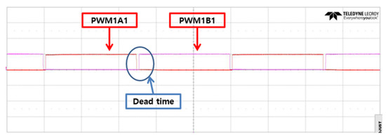
Figure 10.
PWM signal waveforms and dead time for phase U in vector control.
In vector control drive systems, producing sinusoidal currents involves substantial computation, including dead-time calculations and coordinate transformations. High-speed operation of medical micro-motors, used for precision machining with low torque and high rotational speeds, requires a strategy focused on stable high-speed operation rather than maintaining a constant torque.
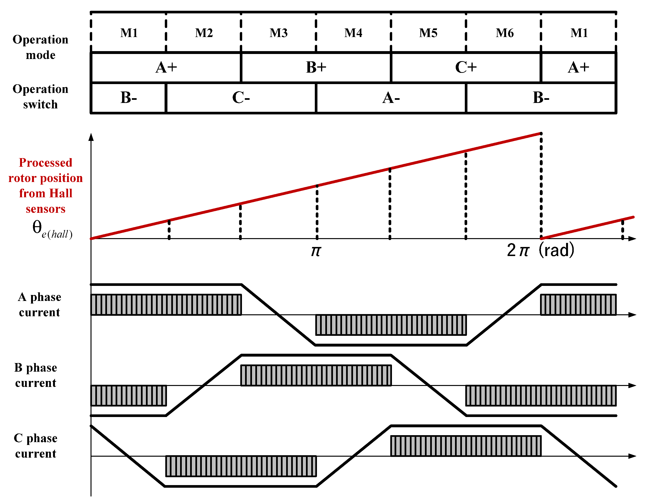
Since the medical device micro-motor discussed in this paper requires high-speed operation exceeding 50 kHz, vector control techniques, which involve substantial computational effort, are not suitable for high-speed operation. Therefore, as shown in Figure 1, it is necessary to transition to a two-phase excitation with six-step commutation, which requires relatively less computation and is suitable for high-speed operation. In the six-step control method, the driving algorithm relies exclusively on two-phase excitation of a three-phase voltage source inverter. Consequently, in high-speed operation, it is essential to eliminate the unnecessary logic associated with the on/off switching of the three-phase inverter and its dead time.
In typical BLDC six-step operation, as shown in Figure 1, the motor is driven through six operating modes using three Hall sensors installed on the motor. However, by utilizing the position signal processed from the Hall sensor signals, it is possible to reconfigure each mode interval into angles, as shown in Figure 11 and Table 1, using the same position information employed for low-speed operation. However, using only the processed for six-step control in high speed mode ensures stable operation at constant speeds but leads to rotor position error during variable-speed ranges.
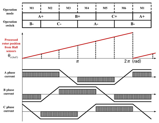
Figure 11.
Reconfigured six-step control mode using the rotor position data processed from Hall sensors.

Table 1.
Commutation mode for a six-step inverter utilizing the processed rotor position in degrees.
Figure 12 illustrates the interval-based sampling strategy in each six-step commutation mode using in variable-speed ranges. Additionally, (12) and (13) represent the equations for calculating the average rotor position for one mode, derived from the entire six-step modes using Equation (6), where denotes the sampling period at each interval. This computational process yields the result given in (14). Therefore, in variable-speed ranges, an improved method is applied to estimate and compensate for the additional angular error that arises relative to the steady-state position value in real-time, as described in Equation (14).

Figure 12.
The strategy for sampling count in each six-step commutation mode using in variable-speed ranges.
By compensating for position errors obtained from (14), it is possible to prevent excessive heating caused by incorrect excitation currents due to position errors in variable-speed operation at high speeds. This facilitates the development of an algorithm for the well-processed rotor position data, as shown in Figure 11.
3.3. Methods for Ensuring Driving Reliability of Micro-Motor
In the case of handpiece motors for dental prosthetics, as previously presented, the system utilizes low-cost micro-motors for machining prosthetics and medical applications. Instead of high-cost precision position sensors, the system employs lower-cost Hall sensors. Low-cost micro-motors are exposed to high-speed operation and variable loads, making them prone to overheating. As a result, the Hall sensors attached to these motors are also at risk of damage from thermal effects, compromising operational reliability. Handpiece micro-motors used directly by users are typically operated with a runtime limited to approximately 40 s to allow for adequate heat dissipation. This approach helps prevent system overload, component damage, and user burns. Hall sensors are crucial for verifying rotor position information, as mentioned in the proposed algorithm. However, if these sensors fail due to issues such as heat during operation, there is a risk of motor stoppage, which could potentially lead to medical accidents. Therefore, a reliable control strategy is essential to ensure stable operation within an extended speed range, even if one or more of the three Hall sensors attached to the micro-motor fail.
Figure 13 shows the position data of the three Hall sensors, individually sampled according to (6).
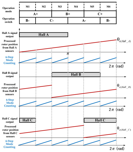
Figure 13.
Position data for each six-step mode in variable-speed operation using three Hall sensors.
Assuming no installation error for the three Hall sensors attached to the micro-motor, the position signals are output with a 120-degree phase difference. Additionally, when the position values are converted for each six-step mode, it is confirmed that they are identical. Therefore, using Hall sensor A as a reference, the actual rotor position can be represented as shown in Figure 9. The position information from Hall sensors A, B, and C can be expressed with a 120-degree phase difference, as indicated in (15). The is obtained from the position data by compensating for the position error using (6) and (7).
Malfunctions in which the three position data obtained from the Hall sensors in (15) may change can be classified into two cases, as shown in Figure 14.
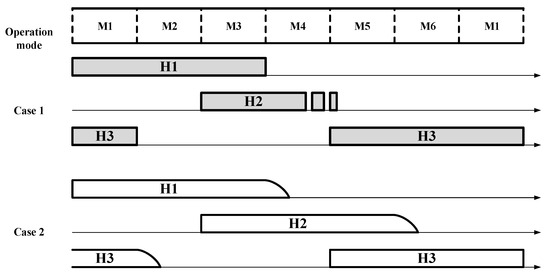
Figure 14.
Analysis of cases involving malfunctions in the three Hall sensors.
Case 1 involves a situation where the malfunction of one or more Hall sensors causes signal discontinuities or output halts. In such cases, the sensor fault can be detected by comparing the measured signal with the reference signal in (15). Additionally, the faulty Hall sensor can be identified through changes in the sampling counting numbers for each six-step mode during constant-speed operation, as shown in Figure 13. Therefore, by applying this comparison method, sensor faults can be identified [13,14]. After excluding the faulty signals, the remaining valid sensor signals can be used to accurately determine the rotor position information and ensure proper operation [15].
Case 2 describes a situation where, in high-speed ranges, all three Hall sensors experience a delay at the signal termination point. Although there is no phase shift among the Hall sensors, this can lead to incorrect commutation relative to the motor parameters, potentially causing excessive heating. In these cases, signal correction can be achieved using the position data calculated from a valid Hall sensor signal and (15) through advanced angle control [16,17].
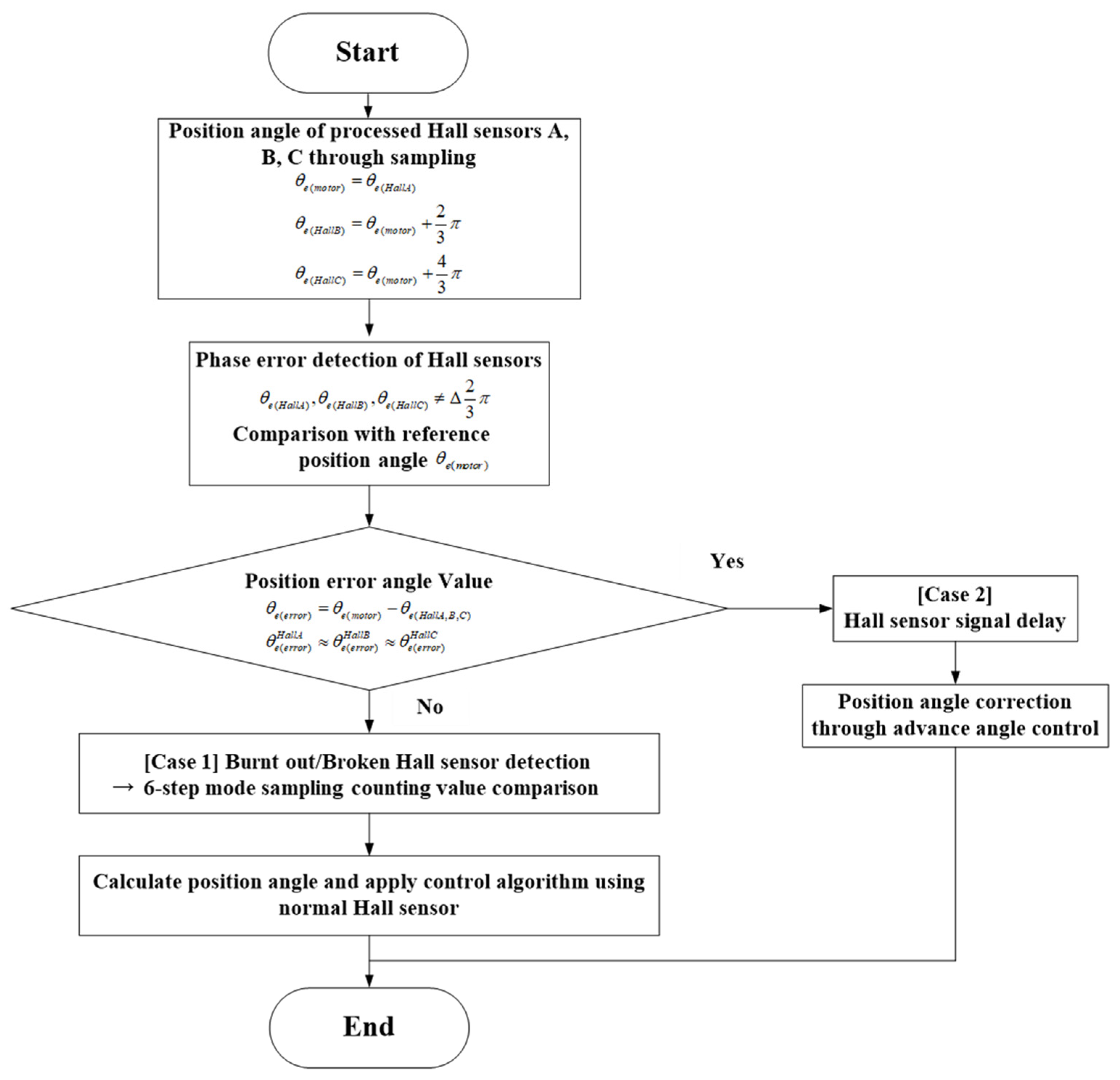
Figure 15 represents the simplified block diagram of the advanced control algorithm for managing Hall sensor malfunctions, based on the fault case analysis and response strategies shown in Figure 14, This algorithm enables real-time comparison and evaluation of position data, allowing for the detection of Hall sensor faults and the position data correction, thereby ensuring reliable operation of the micro-motor.
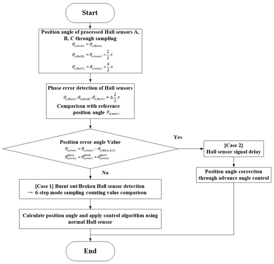
Figure 15.
Block diagram of the fault detection and position data correction algorithm for Hall sensors.
The first step in the diagram of Figure 15 begins by comparing the processed Hall sensor signal with the waveforms of the three Hall sensors. Each Hall sensor signal is designed to have a mechanical phase difference of 120 degrees, allowing the system to computationally detect errors occurring in each signal.
The occurrence of the position error value in Figure 15 can be classified into two cases. Case 2 refers to the signal delay of the Hall sensor, which commonly occurs in high-speed operation. In such cases, although the intervals between the signals of each Hall sensor remain consistent, the 120-degree phase difference decreases. This can be resolved through lead angle control.
In Case 1, this occurs when the signal intervals of the three Hall sensors are not consistent, which indicates a malfunction in one of the Hall sensors. An algorithm capable of detecting the faulty Hall sensor operates, excluding it from signal sampling. The algorithm ensures that stable position signals are maintained by utilizing the signals from the remaining functional Hall sensors, demonstrating how stable operation is achieved.
4. Speed Control Performance Test of the Micro-Motor System Using a Prototype
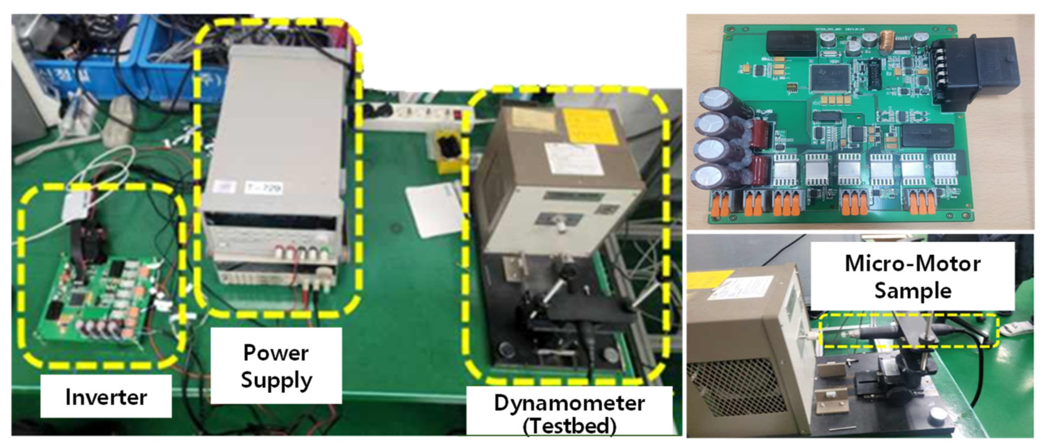
To validate the proposed algorithm for expanding the speed operation range of the micro-motor, the experimental configuration was implemented as shown in Figure 16. The inverter specifications for driving the micro-motor involved using the TI TMS320F28335 MCU for sampling Hall sensor position signals and generating position data. The Micro Commercial MCU20N10-TP (100V, 20A) was used for the three-phase inverter’s power MOS-FET, and the ACS725LLCTR-20AB was used for the three-phase current sensors, with sufficient margin to tolerate potential spike components during inverter switching. Additionally, auxiliary circuits, including filter circuits for noise reduction and communication circuits for motor drive, were implemented for the experimental setup.

Figure 16.
Experimental setup for validating the micro-motor operating range expansion algorithm.
The main parameters of the target micro-motor used in the experiments are listed in Table 2. The medical micro-motor has a high maximum speed, allowing for a relatively wide speed operation range. However, to extend this speed range, it is essential to implement strategies for high-torque operation in the low-speed range and stable high-speed operation in the high-speed range for precise control, as previously discussed. Due to the thermal limitations characteristic of medical handpiece motors, it is common to operate them with reduced current and limited runtime. Therefore, in this study, experiments were conducted under low-speed, high-torque operation and at a speed of 50,000 rpm, with the current limited to a maximum of 3 Arms.
Table 2.
Micro-motor parameters.
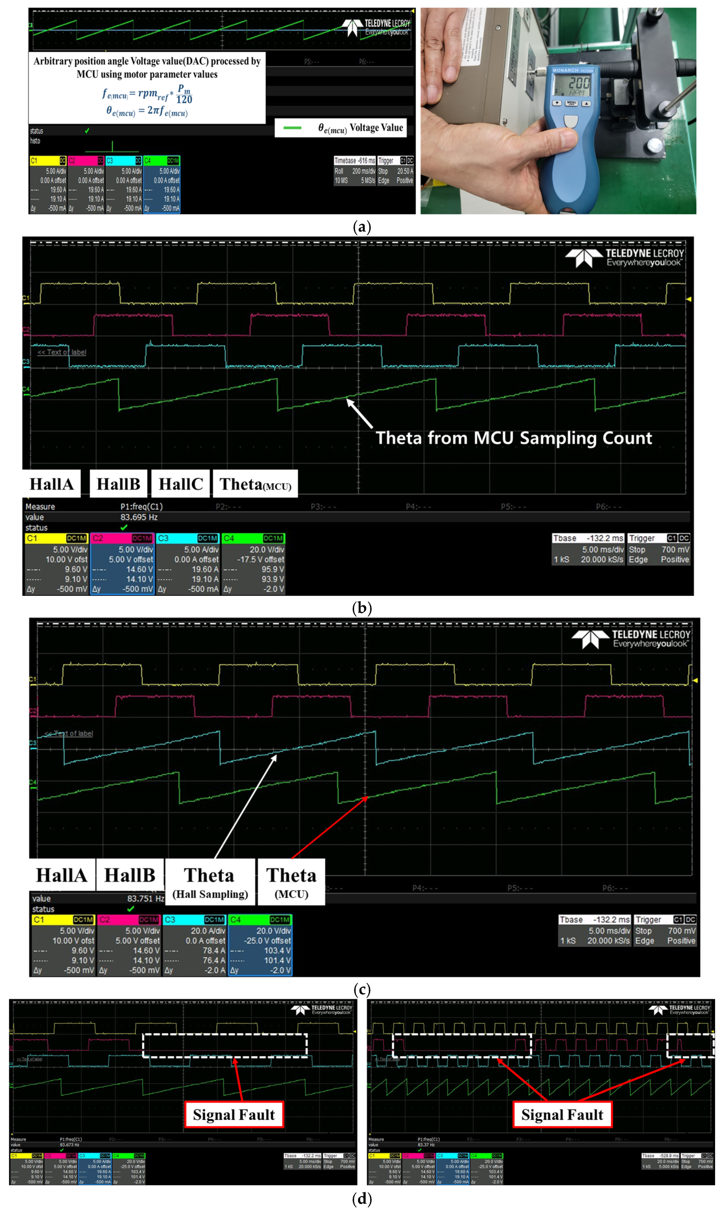
To achieve low-speed, high-torque drive control for dental implant placement using -based control, a speed reference of 200 rpm and a -axis current of 1.5 A were applied. Figure 17a shows the output values on the oscilloscope of calculated by the MCU and output via the DAC (Digital to Analog Converter) in the extreme low-speed range (200 rpm), as well as the speed measurements obtained using an external speed sensor. From the experimental results, the implementation of stable control performance was verified in low-speed mode. In addition, Figure 17b,c show the position signals calculated using the MCU and the position signals calculated through Hall sensor sampling, respectively. Figure 17d shows the results of stable position signals being calculated even when faults occur with the sensor signals.
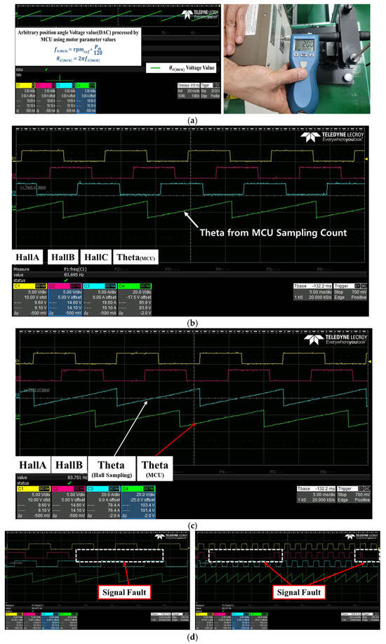
Figure 17.
(a) Output waveform conversion of and speed measurement in extreme low-speed mode (200 rpm). (b) Waveforms of processed position signals through MCU computations and Hall sensor signals. (c) Waveforms of position signals processed through the Hall sensor and position signals processed through MCU computations. (d) Verification of stable position signals output even when the Hall sensor stops functioning.
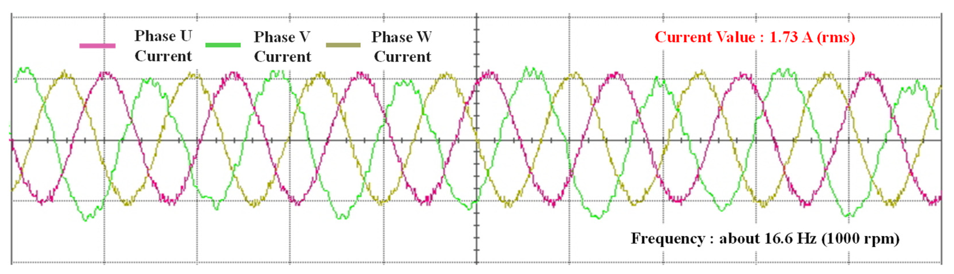
Based on a stable signal from the Hall sensor at 1000 rpm, the position error was eliminated using a PI controller, and the processed rotor position was applied to the control algorithm. Figure 18 shows the current waveform results for constant-speed operation at 1000 rpm using the position signal processed through the Hall sensors, applying the rotor position transition algorithm from Figure 8. The proposed rotor position transition algorithm was experimentally verified.
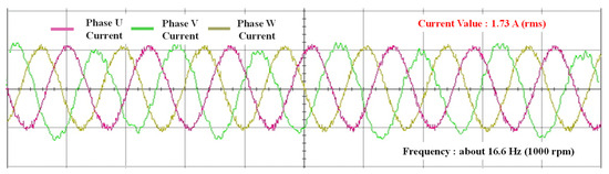
Figure 18.
Current waveform results for low-speed mode (1000 rpm) using .
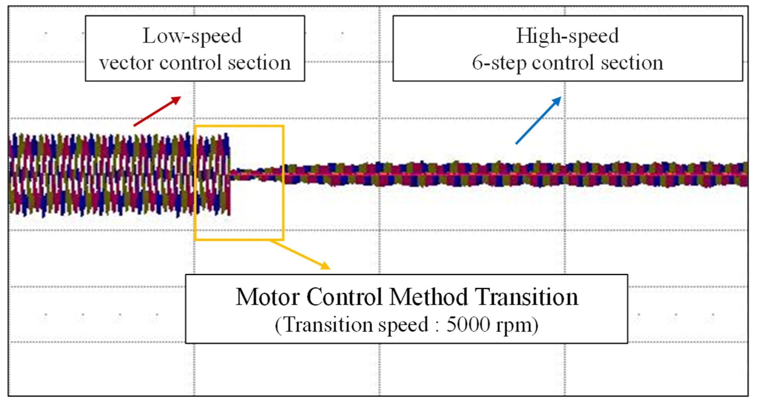
The speed requirements for machining hard prosthetic materials are typically met in the range below 5000 rpm. Therefore, to address the demands of high-speed operation, the proposed control method transition algorithm was implemented with a threshold set at 5000 rpm. Figure 19 represents the current waveforms obtained during the transition to six-step control from low-speed vector control to high-speed operation as the speed increases, based on the rotor position transition algorithm presented in Figure 8. As the speed increases during six-step control, it can be confirmed that the current ripple does not occur significantly in the variable speed range, verifying that the position error is well compensated.
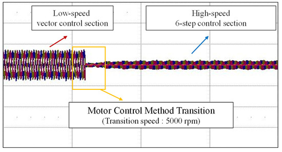
Figure 19.
Current waveform resulting from the proposed control transition algorithm for high-speed operation (5000 rpm transition).
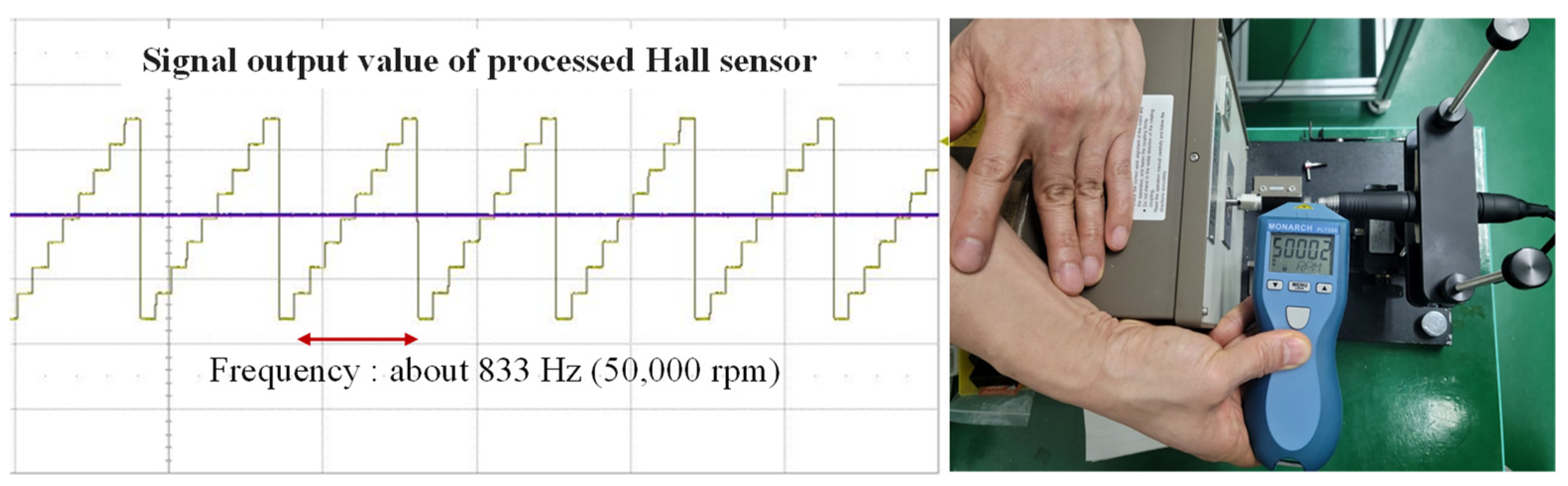
Figure 20 represents the voltage conversion values for the position signal using a DAC, demonstrating a consistent six-step commutation interval, utilizing the position data in the high-speed range (50,000 rpm). This indicates that the transition to high-speed operation was efficiently achieved and stable speed control is being maintained.

Figure 20.
Output waveform conversion of and speed measurement in extreme high-speed mode (50,000 rpm) using the proposed algorithm.
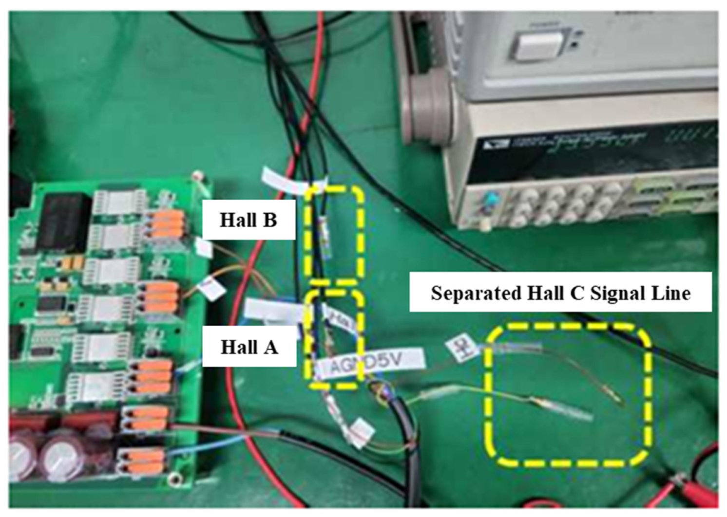
Figure 21 shows the test case of intentionally disconnecting the Hall sensor signal lines during operation to simulate sensor malfunctions for the purpose of validating the position data transition algorithm depicted in Figure 15.
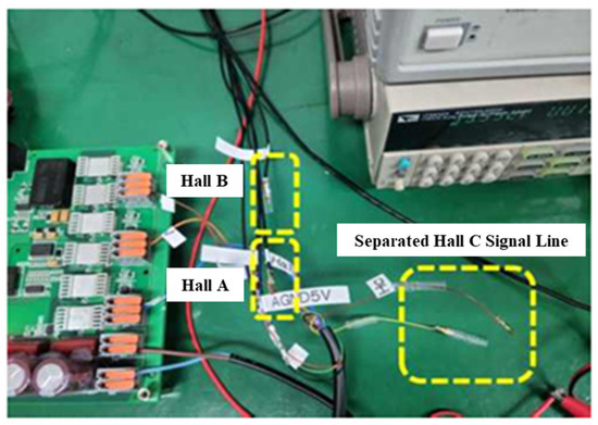
Figure 21.
Separation of Hall signal lines for validating the proposed fault detection and rotor position transition algorithm.
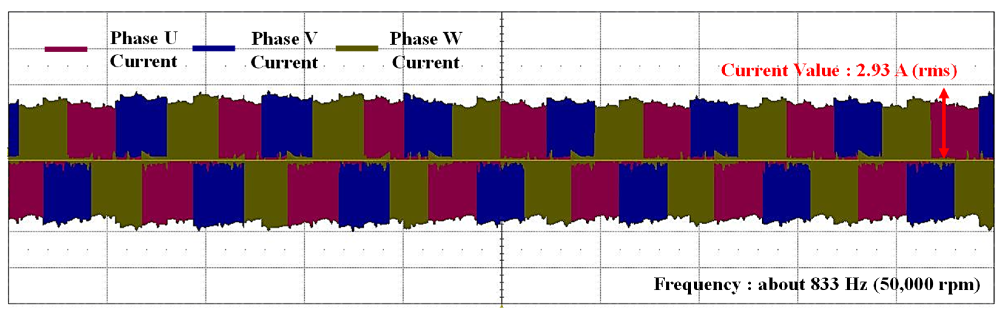
Finally, Figure 22 shows the three-phase current waveforms when a fault was injected into the Hall signal during operation at 50,000 rpm, as depicted in Figure 21. At the most extreme range, with a maximum speed of 50,000 rpm, the mechanical and electrical frequencies of the target two-pole motor are both 833.33 Hz. Despite the high-speed frequency, control was achieved without issues under the condition of a 10 kHz switching frequency, using two-phase commutation and the six-step control algorithm. From the experimental results, it was verified that the position data correction algorithm, which can determine the failure of the Hall sensor in real time, as explained in Figure 15, and maintain stable operation even in the event of a sensor failure based on the normal Hall sensor signal, is appropriately controlled.

Figure 22.
Current waveform at high-speed of 50,000 rpm in the event of a Hall sensor failure.
The BLDC control method based on digital Hall sensors has drawbacks in low-speed, high-torque operating mode due to low resolution and torque ripple at low speeds. As a result, applying the commonly used six-step control method in BLDC control can increase non-linear motor operation and harmonic distortion, causing a decline in precision for position and speed control at low speeds, as well as an increase in torque ripple [8,9,18,19,20]. On the other hand, in situations where precise and consistent control performance is crucial at low speeds, more accurate control methods, such as Field-Oriented Control (FOC), are necessary. To implement vector control techniques in low-speed, high-torque operation mode, we applied the FOC method through the generation of position prediction signals.
For medical micro-motors, high-speed control performance is also important for precision machining. The conventional FOC control method requires extensive computations, including dead-time processing and coordinate transformations, to output sinusoidal currents. This is particularly unsuitable for high-speed applications due to the increased computational load and the requirement for expensive sensors. To address this, the algorithm transitions to two-phase excitation with the six-step driving method, maintaining relatively fast computation speeds while enabling effective high-speed operation. Additionally, by applying fault detection and compensation algorithms for potential failures of Hall sensors in high-speed regions, the reliability of high-speed operation has been further improved.
Therefore, in systems that frequently require low-speed, high-torque and ultra-high-speed operation, it is essential to develop algorithms that allow for rapid and smooth transitions to enhanced control modes in the low-speed, high-torque and mid-speed ranges.
5. Conclusions
This paper proposes a method to expand the operational range of micro-motors using low-cost Hall sensors, while ensuring precise control and driving reliability. This study presents methods for acquiring enhanced position data and robust control strategies for managing load torque in the low-speed range. It also introduces approaches for achieving high-speed with precision control and provides a method for compensating rotor position errors during the transition from low-speed to high-speed mode. Additionally, this study addresses fault detection and mitigation strategies for Hall sensors, which are prone to failure, to ensure stable position data acquisition in micro-motors. Finally, it is validated that, based on the proposed method, the medical micro-motor system for precision machining can operate stably over a wide speed range with the experimental results.
This study anticipates that the control method for a wide operating range of the precision machining micro-motor using a low-cost Hall sensor, along with the reliability improvement strategy for the motor system, will enhance the reliability of medical devices and secure a competitive edge. Additionally, it is anticipated that the research results and control methods from this study can be applied to fields requiring low-speed, high-torque and ultra-high-speed operations, such as aerospace, precision machinery, robotics, and biomedical devices.
Author Contributions
Conceptualization, J.S.L. and G.P.; methodology, J.S.L.; software, J.S.L.; validation, J.S.L. and G.P.; formal analysis, G.P.; writing and original draft preparation, G.P.; writing, review, and editing, J.S.L.; supervision, J.S.L.; project administration, G.P.; and funding acquisition, G.P. All authors have read and agreed to the published version of the manuscript.
Funding
This work is supported by the development project of the auto-stow electric column mechanism system for SbW with a long-stroke ball sliding structure (Grant No. RS-2023-00280208) from the Ministry of SMEs and Startups, Korea.
Data Availability Statement
Data are contained within the article.
Conflicts of Interest
The authors declare no conflicts of interest.
References
- Zakeri, V.; Arzanpour, S. Studying the design of PWM controllers for air motors with an indirect approach of speed measurement. In Proceedings of the ASME International Mechanical Engineering Congress Exposition, IMECE, Vancouver, BC, Canada, 12–18 November 2010. [Google Scholar]
- Dyson, J.E.; Darvell, B.W. Flow and free running speed characterization of dental air-turbine handpieces. J. Dent. 1999, 27, 465–477. [Google Scholar] [CrossRef] [PubMed]
- Zakeri, V.; Arzanpour, S. A speed regulating scheme for air-turbine dental handpieces. In Proceedings of the 2012 American Control Conference (ACC), Montreal, QC, Canada, 27–29 June 2012; pp. 2356–2361. [Google Scholar] [CrossRef]
- Im, W.S.; Kim, J.P.; Kim, J.M.; Baek, K.R. Torque maximization control of 3-phase BLDC motors in the high-speed region. J. Power Electron. 2010, 10, 713–723. [Google Scholar] [CrossRef]
- Moon, J.-J.; Im, W.-S.; Kim, J.-M. Novel phase advance method of BLDC motors for wide range speed operations. In Proceedings of the 2013 Twenty-Eighth Annual IEEE Applied Power Electronics Conference and Exposition, Long Beach, CA, USA, 17–21 March 2013; pp. 2343–2348. [Google Scholar]
- Ogasawara, S.; Akagi, H. An approach to position sensorless drive for brushless dc motors. IEEE Trans. Ind. Appl. 1991, 27, 928–933. [Google Scholar] [CrossRef]
- Shao, J. An improved microcontroller-based sensorless brushless DC (BLDC) motor drive for automotive applications. IEEE Trans. Ind. Appl. 2006, 42, 1216–1221. [Google Scholar] [CrossRef]
- Tang, Y.; Liu, X.; Zhang, W.; Wang, H. Torque Ripple Reduction in Six-Step Controlled Permanent Magnet Motors. Electronics 2020, 9, 1234. [Google Scholar]
- Williamson, S.S.; Su, W.; Li, M.; Yang, Y. A Comparative Study of Six-Step and Field-Oriented Control for Permanent Magnet Synchronous Motors. Electronics 2021, 10, 567. [Google Scholar]
- Ungurean, A.; Coroban-Schramel, V.; Boldea, I. Sensorless control of a BLDC PM motor based on I-f starting and back-EMF zero-crossing detection. In Proceedings of the 2010 12th International Conference on Optimization of Electrical and Electronic Equipment, Braşov, Romania, 20–22 May 2010; pp. 377–382. [Google Scholar]
- Dong, L.; Huang, Y.; Jatskevich, J.; Liu, J. Improved Fault-tolerant Contorl for Brushless Permanent Magnet Motor Drives with Defective Hall Sensor. IEEE Trans. Energy Conv. 2016, 31, 789–799. [Google Scholar] [CrossRef]
- Fang, J.; Li, W.; Li, H. Self-Compensation of the commutation angle based on DC-Link current for high-speed brushless DC motors with low inductance. IEEE Trans. Power Electron. 2014, 29, 428–439. [Google Scholar] [CrossRef]
- Scelba, G.; De Donato, G.; Pulvirenti, M.; Capponi, F.G.; Scarcella, G. Hall-effect sensor fault detection, identification and compensation in brushless DC drives. In Proceedings of the 2015 IEEE Energy Conversion Congress and Exposition, ECCE, Montreal, QC, Canada, 20–24 September 2015; Volume 52, pp. 3987–3995. [Google Scholar]
- Scelba, G.; De Donato, G.; Pulvirenti, M.; Capponi, F.G.; Scarcella, G. Hall-Effect Sensor Fault Detection, Identification, and Compensation in Brushless DC Drives. IEEE Trans. Ind. Appl. 2016, 52, 1542–1554. [Google Scholar] [CrossRef]
- Woo, M.S.; Yoon, Y.H.; Lee, S.J.; Won, C.Y.; Choe, Y.Y. Comparison of characteristics using two Hall-ICs and one Hall-IC for 3 phase slotless PM brushless DC motor. In Proceedings of the 30th Annual Conference of IEEE Industrial Electronics Society IECON 2004, Busan, Republic of Korea, 2–6 November 2004; Volume 2, pp. 1380–1384. [Google Scholar]
- Park, J.S.; Lee, K.-D. Online Advanced Angle Adjustment Method for Sinusoidal BLDC Motors with Misaligned Hall Sensors. IEEE Trans. Power Electron. 2017, 32, 8247–8253. [Google Scholar] [CrossRef]
- Tozune, A.; Takeuchi, T. Improvement of torque-speed characteristics of brushless motor by automatic lead angle adjustment. In Proceedings of the 4th International Power Electronics and Motion Control Conference, Xi′an, China, 14–16 August 2004; Volume 2, pp. 583–587. [Google Scholar]
- Campos, R.d.F.; Liberato, C.d.S.; Oliveira, J.d.; Dezuo, T.J.M.; Nied, A. Dynamic Strategy for Effective Current Reduction in Brushless DC Synchronous Motors Fault Tolerant Operation. Energies 2022, 15, 9323. [Google Scholar] [CrossRef]
- Garmut, M.; Steentjes, S.; Petrun, M. Optimization of an IPMSM for Constant-Angle Square-Wave Control of a BLDC Drive. Mathematics 2024, 12, 1418. [Google Scholar] [CrossRef]
- Zhang, P.; Shi, Z.; Yu, B.; Qi, H. Research on the Control Method of a Brushless DC Motor Based on Second-Order Active Disturbance Rejection Control. Machines 2024, 12, 244. [Google Scholar] [CrossRef]


Disclaimer/Publisher’s Note: The statements, opinions and data contained in all publications are solely those of the individual author(s) and contributor(s) and not of MDPI and/or the editor(s). MDPI and/or the editor(s) disclaim responsibility for any injury to people or property resulting from any ideas, methods, instructions or products referred to in the content. |
© 2024 by the authors. Licensee MDPI, Basel, Switzerland. This article is an open access article distributed under the terms and conditions of the Creative Commons Attribution (CC BY) license (https://creativecommons.org/licenses/by/4.0/).