Abstract
The joint beamforming optimization from the perspective of the bit error rate (BER) in a reconfigurable intelligent surface (RIS)–assisted intelligent communication system is studied in this paper. A genetic algorithm (GA) is investigated to address the bottleneck of the system performance based on the dynamic adaptability theory. However, the bottleneck is caused by the interaction between the active and passive beamforming. To tackle the constraints of conventional optimization approaches, the hybrid scheme is proposed to combine the GA optimization (GAO) and fully connected neural network (FCNN) strategy. Specifically, the intelligent collaborative tuning of system parameters is achieved using this proposed technique. Simulation findings indicate that the hybrid scheme not only simplifies the calculation process to obtain the optimal network parameters, but also effectively optimizes the system structure by dynamically adjusting the RIS reflection configuration. Based on this, the signal transmission quality is improved, interference is reduced, and the stable and efficient operation of the RIS–assisted intelligent communication system is ensured in the complex wireless transmission scenario.
1. Introduction
With the continuous evolution of communication technology, especially the vigorous development of fifth generation (5G) technology, a host of applications have become increasingly comprehensive, such as intelligent manufacturing, smart cities, telemedicine, and so on. In this context, the reconfigurable intelligent surface (RIS), as an emerging wireless communication technology, has demonstrated a significant potential for the future of 6G communication systems [1,2]. In references [3,4], the investigation of the optimization of attainable rates in unmanned aerial vehicle (UAV) scenarios in multiple–input single–output (MISO) networks was conducted. A new perspective on the application of an RIS in dynamic environments was provided by this study. In reference [5], a capacity optimization algorithm for RIS–assisted multiple–input multiple–output (MIMO) communication systems was proposed. Specifically, an RIS is composed of many adjustable passive reflection components. By adaptively controlling the phase and amplitude of each reflective unit, the beamforming and directional discipline of the incident signal can be realized. As a consequence, the signal reception quality was enhanced, and the multi–path interference was eliminated and improved effectively [6]. Additionally, efficient reuse of space resources can be achieved by an RIS through the precise beamforming with reduced user interference. The authors in [7] showed that the coverage performance of the system can be greatly improved by optimizing beamforming in the RIS–assisted network. It provided an important theoretical basis for subsequent research. On this basis, the authors in [8] further explored the MIMO channel covariance matrix as well as optimized the autonomous phase shifts and/or magnitudes of the RIS. Moreover, the beam can be dynamically adjusted to accommodate user position changes to ensure a sustained effect of interference suppression.
Unlike the conventional intelligent large–scale MIMO communication system [9], an RIS incorporating a passive reflective surface was introduced in the modern mobile communication systems without any transmitting or receiving function modules. The key benefit of integrating the RIS lies in its unparalleled capacity to manipulate the propagation trajectory [10] of incoming signals dynamically. Furthermore, the space resource reuse was achieved through the meticulous tuning. And phase shifts and amplitudes can be controlled by the myriads of reflective elements embedded within the RIS surface. This process offered a high level of precision and adaptability that exceeded traditional signal control methods [11,12,13]. Based on this, significant improvements of signal coverage and communication efficiency can be achieved without additional energy consumption. As a consequence, the potential performance of the RIS can be realized through close collaboration among the base station (BS), user terminals, and the RIS. Additionally, the joint optimization of beam assignment parameters was studied to enhance the performance of the interruption probability [14,15,16,17] and symbol error rate (SER) [18,19,20]. In reference [21], it was found that the security of the physical layer link was greatly improved. This improvement was obtained when beamforming vectors at the input point and the RIS were combined. However, the joint beamforming problem was complex and it was difficult to obtain a direct closed–form solution due to its highly nonconvex property [22,23,24,25]. Traditional methods are often hindered by the stagnation in local optima, thereby the satisfactory performance is hard to achieve. Consequently, suboptimal methods are investigated by academic and industrial scientists. Among these schemes, the optimization methods based on the secondary planning [26] were explored due to its simplicity. The computational complexity was reduced by transforming the complex nonconvex problem into a tractable secondary programming problem through the convexation and linearization disciplines. However, its local optimal solution was inherently confined [27,28], and it was difficult to obtain the global optimization in the scenario of high–performance demands.
In this paper, a deep learning–enhanced genetic algorithm (GA) is proposed to develop a sophisticated RIS–assisted intelligent communication system model leveraging fully connected neural networks (FCNNs). Our approach is driven by the high computational complexity of communication systems, and various challenges existed in conventional optimization techniques, especially for the beamforming optimization of both transmitters and receivers. Various literatures have underscored the nonconvex challenges of optimization problems in this field. And now, suboptimal solutions are often obtained due to the local minima. Fortunately, this issue is tackled by overcoming the nonconvex obstacles by using our GA optimization (GAO). In addition, the cooperative optimization of the RIS reflection matrix and the beam assignment vector is also studied here. Furthermore, the robust modeling capabilities of FCNNs are explored to enhance the capacity of complex patterns identification in the RIS–assisted wireless communication system. Based on this, the enhancement of the system efficiency and dependability is improved. Numerical simulation results indicate that our proposed method markedly surpasses existing techniques from the perspective of bit error rate (BER) performance. And the exceptional efficiency and reliability of the deep learning–augmented GA/GAO in this paper can be affirmed. Consequently, complex communication optimization challenges in the RIS–assisted system are overcome. Moreover, contributions are made in this paper to the ongoing development of the intelligent communication system, and it is particularly important for the evolution of 6G mobile information networks.
Notation: The bold lowercase and uppercase letters are used to represent the vectors and the matrices, respectively. is the conjugate transpose of the vector , and is the corresponding transpose.
2. System Model
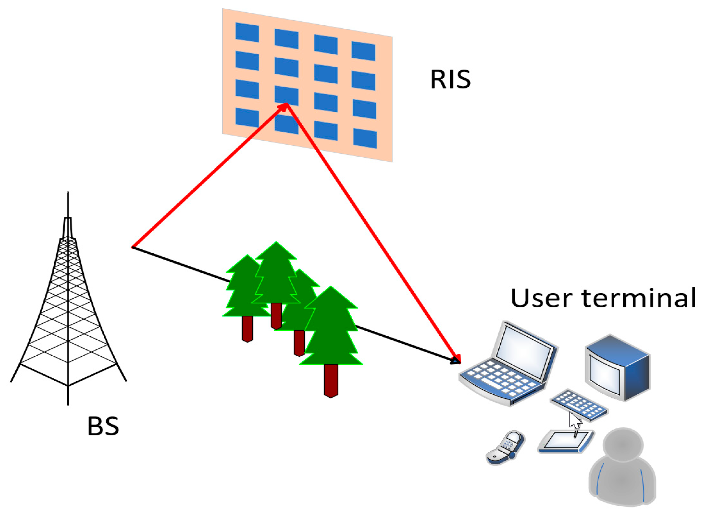
As depicted in Figure 1, a downlink intelligent MIMO wireless communication system is considered in this paper. The BS has BS antennas, the RIS has reflection elements, and the receiver has antennas. During the process of collaborative beamforming, both the transmission beamforming array associated with the BS and a reflection beamforming array belonging to the RIS should be refined. The emission direction of the signal is controlled by adjusting its emission beamforming vector [29,30]. And each unit of the beamforming vector represents a unique weight assigned to each BS antenna. These weights are utilized to adjust both phase and magnitude of the transmitted signal, known as the transmit precoding. The incoming signal received at the RIS is given by
where is the transmitted signal vector, represents the received signal, is the channel response between the BS and RIS, and represents the noise vector at the RIS. Therefore, the reflection signal matrix on the RIS (i.e., the signal reflected by the RIS) can be expressed as
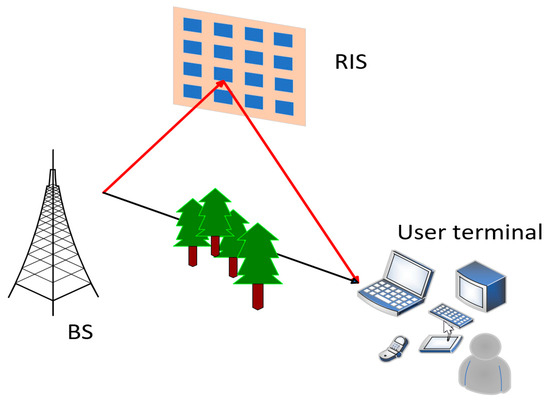
Figure 1.
The RIS–assisted intelligent downlink MIMO communication system.
The signal transmitted by the BS passes through the channel to the RIS. Subsequently, it is bounced back by the RIS in accordance with this reflection phase matrix , where represents the matrix of reflection phases associated with the RIS. It is expressed as
where represents the elements on the diagonal, is the imaginary unit, represents the phase of the m-th reflective component in radians, and is the magnitude reflection factor of the m-th unit of an RIS. They are respectively given by in the following equation:
Next, the signal obtained at the receiver through different channel propagation links is expressed as
where represents the direct channel link matrix, represents the channel matrix between the BS and the RIS, is the channel matrix between the RIS and the receiver, is the beamforming vector of the BS, and is the transmitted symbol. It is assumed that the channel responses in the downlink follow an independent and identical distribution with zero mean, and represents the additive white Gaussian noise (AWGN) vector.
This joint beamforming problem is focused on optimizing system performance by adjusting transmission parameters collaboratively. These parameters belong to the following multiple nodes: the transmitter, the receiver, and the RIS. Additionally, maximizing signal–to–noise ratio (SNR) or minimizing BER is the key metric of performance improvements. However, minimizing BER directly is often very complex, since the expression of the BER may contain intractable integrals or summations. As a consequence, our technique is aimed to optimize the SNR of the received signal to achieve the optimization goal. It can be expressed as follows:
where is the maximum power, is the L2–norm function, and is the square of the L2–nom of .
Then, the SNR is specified as the ratio between the received signal strength and the noise power. In this case of multiple antennas, the received signal power is and the noise power is (assuming that the noise power at each received antenna is ). Consequently, the SNR is expressed as
If , it can be further simplified as
where is the square of the L2–norm of .
3. GAO–FCNN
3.1. Fully–Connected Neural Network
The FCNN is based on the connection weights and bias between neurons, as well as the nonlinear properties of the activation mechanism. And these weight values and biases are combined with the neural network via a linear process. This is followed by a nonlinear transformation applied by the activation function. This combination enables the network to perform the complex feature extraction and pattern recognition according to the input data. As a result, the network is able to map the input data to the corresponding output labels, and learn some provided examples effectively.
After then, to retrieve the original bit sequence of the time–dependent channel, the minimization of the cross–entropy (CE) loss function is performed during the training process. It is expressed as
where is the CE loss function, is the quantity of training samples and it is utilized to evaluate , is the input bit sequence, is the number of the bit sequence, and is the soft bit sequence.
Next, the input bit sequence is subjected to a transformation process involving three fully connected layers. The first layer is employed using the ReLU activation function [31] and the undergoing BatchNorm1d normalization just as it is shown in Algorithm 1 to carry on the linear transformation. In addition, the activation function is also computed here. Finally, the activation value of the first output layer is given by
where is the activation value vector of the first layer, is the first weight vector of the i-th training sample, is the bias of the first layer, is the predicted output of the first layer, is the sigmoid activation function in the first layer, and the BatchNorm1d normalization is provided by
where is the data entered into the BatchNormld layer, and it is usually the characteristic data within a lot (batch); is the mean value of the input data in a certain dimension; is the variance of the input data with the same dimension; is a very small positive number used to prevent the denominator from being zero; and and are the scaling factors and the translation factors learned by the BatchNorm1d layer, respectively.
Furthermore, the same operation is repeated in the second layer. And the activation value of the second output layer is given by
where is the activation value vector of the second layer, is the second weight vector of the i-th training sample, is the bias of the second layer, is the predicted output of the second layer, and is the sigmoid activation function in the second layer.
The third layer is the output layer; it does not contain the activation function. The bias is usually a scalar element and the activation value of the final output layer is given by
where is the activation vector of the third layer, is the third weight vector of the i-th training sample, is the bias of the third layer, is the predicted output of the third layer, and is the sigmoid activation function of the third layer.
The signal flow is performed at the at the user side, with two fully connected layers, that is,
where is the first activation value vector of the i-th training sample, is the first weight vector of the i-th sample, is the second weight vector of the i-th training sample, is the signal obtained at the receiver via the direct connection without RIS and the RIS–assisted channel links, is the first bias of the i-th training sample, is the second bias of the i-th training sample, and represents the output of the i-th training sample after passing through the second layer.
Here, the transmitter, the channel, and the receiver are implemented as auto encoders using this FCNN. The trainable weight values are trained by using both and to link neighboring layers. The network modeling parameters of both the transmitter and the receiver are fine–tuned to concurrently recreate the inputs of the transmitter at the receiving side. The mini–batch gradient descent (MBGD) algorithm is used here to update the transmitter weight , the reflection phase of the RIS , and the receiver weight . The gradient of the weight and the weight is calculated according to the derivations of the CE loss function. In the subsequent, the FCNN is accomplished based on the connection weights, bias between neurons, and nonlinear properties of the activation function. The complex feature extraction and pattern recognition of the data are performed by the linear combination of weights and bias, as well as the nonlinear transformation provided by the activation function. Consequently, the mapping and learning steps of the input data and the output labels are given in Algorithm 1 to update and for all layers .
Firstly, errors of the output layer are
where is the error of the L-th layer, is the gradient vector of , is the predicted output of the L-th layer, is the target of our model optimization, and is the derivative of the L-th layer activation function.
Then, the back–propagation error is subsequently given by
where is the error of the l-th layer at the transmitter, is the weight vector of the (l + 1)-th layer, represents the element multiplying point by point, is the derivative of the l-th layer activation function, is the error pertaining of l-th layer at the receiver, is the weight vector of the (l + 1)-th layer, is the derivative of the l-layer activation function, is the error of the l-th layer of reflection phases associated with the RIS, is the matrix of the (l + 1)-th layer of reflection phases, is the derivative of the l-th layer activation function at the receiver, is the error of the l-th layer, is the error pertaining to the bias of the (l + 1)-th layer, and is the derivative of the l-th layer activation function at the receiver.
Consequently, , , and can be updated as shown below:
i.e.,
where is the weight vector of the l-th layer at the transmitter, denotes the learning rate, is the gradient vector of the l-th layer at the transmitter of , is the weight vector of the l-th layer at the receiver, is the gradient vector pertaining to the l-th layer of , represents the matrix of the l-th layer of reflection phases associated with the RIS, is the gradient vector pertaining to the l-th layer of , is the bias of the l-th layer, and is the gradient vector pertaining to the l-th layer of .
Then, according to Algorithm 1, the weight regularization loss is used to prevent the model overfitting as follows:
where is the regularization coefficient, and and are the computation results of the L2–norm function.
| Algorithm 1: The essential process pertaining to the FCNN |
| # forward propagation |
| Input: |
| Initialize: |
| For every layer from 1 to do: |
| # Linear transformation |
| # Activation function |
| Output: (activation values of the final output layer) |
| # back propagation |
| Input: (true labels), CE loss function |
| Initialize: means derivative of the normalized output vector l-th layer with respect to |
| For each layer from 1 to do: |
| If is not the output layer: |
| Compute the weight regularization loss |
| Else: |
| # Compute gradient |
| # Compute weight gradient |
| = np.sum(, axis = 1, keep dims = True) # Compute bias gradient, axis = 1 sums across rows |
| # Update weight values and biases |
| Output: Updated and for all layers |
3.2. Genetic Algorithm Optimization
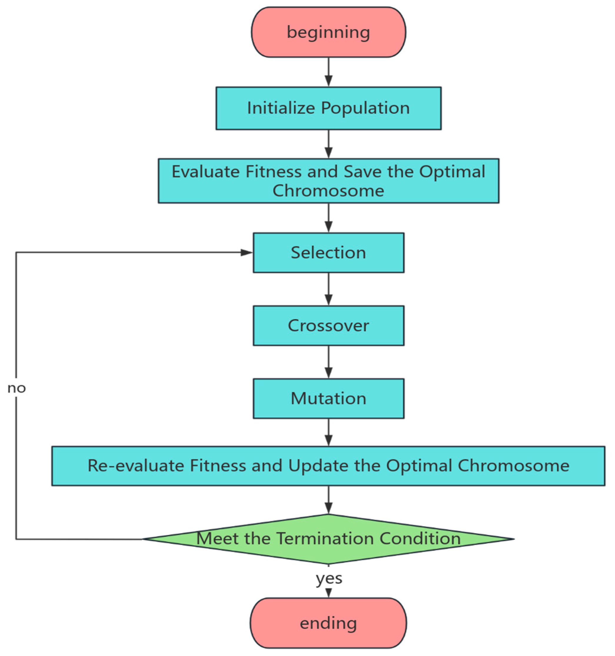
As shown in Figure 2, the network parameters are optimized using GA. Firstly, some preparations are defined as follows. is represented as FCNN to denote weight matrices, is represented as bias vectors, and is represented as the number of layers. For each weight and bias , they are first converted to floating point numbers within , then these floating–point numbers are converted to binary strings of length 4. Individuals are encoded as
so that the first step is carried on to initialize the population in Figure 2. According to Equation (22), the number of individuals is defined as the size of the initial population and each individual in the population is expressed as a set of coded weights and bias . These encoded individuals allow GA to explore different FCNN parameter configurations in the searching space. And the population can be subsequently initialized as
where represents the population size, and is the population.
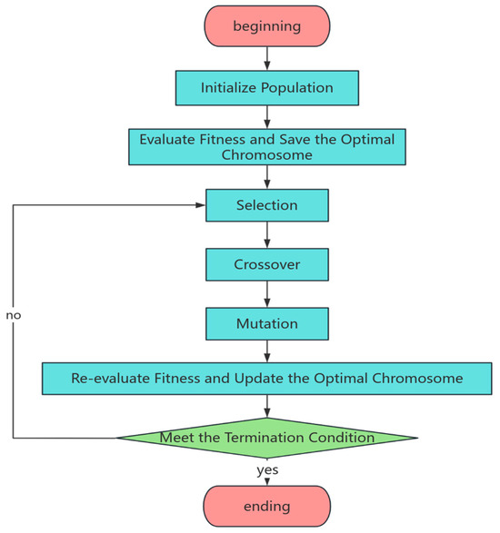
Figure 2.
Genetic algorithm optimization flowchart.
Here, configurations of FCNN are defined as individuals. Then each individual can be trained by FCNN to calculate the output of through forward propagation. Consequently, the loss function is given by
where denotes the actual value matching the o-th sample, and is a predicted value of the o-th sample.
Then, the next step is carried out to evaluate the fitness. Here, the individual performance is evaluated by computing the error between the output of FCNN and actual values. A higher fitness level means a better effectiveness of each individual. Afterward, the optimal chromosome (i.e., the best FCNN configuration) is saved following the third step in Figure 2. As shown in Algorithm 2, the evaluation of the adaptive value function is denoted by
so that the optimal chromosome (i.e., the best FCNN configurations) can be saved according to Algorithm 2.
Then, the next step is carried out to select the best individual in Figure 2. Here, the best FCNN configurations are selected by using the roulette algorithm. The idea is to convert fitness values into selection probabilities using a “roulette” method. Therefore, individuals with higher fitness are more likely to be chosen to ensure that better genes are retained. The performance metrics of each network configuration are firstly calculated. Then, the selection probability of each configuration is determined based on its corresponding performance metrics. It can be given by
where is a function to determine the selection probability of each configuration and the signal strength enhancement or interference minimization under specific channel conditions can be achieved according to the designed performance metrics. Notably, network configurations with higher performance metrics are more likely to be selected in practice and the quality configurations are retained for performing the next generation. Subsequently, the crossover step is provided in Figure 2. It is performed using a single–point crossover to generate offspring in GAO, following the crossover process of Algorithm 2:
After that, variation operations are performed as shown in Figure 2. The corresponding steps are demonstrated in Algorithm 2. Weight values are updated using gradients, and bias variants are adjusted accordingly. New values are applied to the model. Then, performance improvements are observed.
where represents the updating of weight value and represents the updating of bias.
Next, the quantity update process is performed. And the new quantity is generated through selection, crossover, and variation operations,
Furthermore, the fitness is reevaluated and the optimal chromosome is updated as shown in Figure 2. If the system performance is not optimized or the termination condition is not fulfilled according to the saved chromosome, steps 3 to 6 will be repeated in Algorithm 2. The maximum number of iterations or generations in Algorithm 2 is defined as the population size (i.e., FESmax = ), and is the evolutionary generation count. So, is the maximum rate parameter of . This is treated as a termination condition. Otherwise, the final output results of GAO can be obtained.
This training process can be concluded when the allowed maximum number of iterations is achieved. And the neural network parameters corresponding to the individual with the best fitness are finally provided,
where represents the optimal neural network parameter configuration of the joint beamforming issue in the RIS–assisted intelligent communication system. It is also the optimal result obtained by the GAO, then it can be used for the replacement in Algorithm 2.
Finally, in order to satisfy the amplitude limitation of the nonactive beamforming matrix , i.e., , the optimization of at each iteration is normalized as outlined as follows:
where represents the highest value of the (i + 1)-th sample in , , …, .
| Algorithm 2: The core process pertaining to the GAO |
| Input: population size , crossover likelihood (Pc = 0.65), mutation likelihood (Pm = 0.025), the maximum allowable number of functions evaluated (FESmax = ) |
| / * z is the current evolutionary generation number, and Best represents the optimal solution currently found, */ |
| Procedure GA |
| z ← 0; |
| ←initialize); // initialize the population |
| ←evaluate) // evaluation of adaptive value |
| keep_best); // save the optimal chromosome |
| FE = |
| while(termination conditions not met) do |
| begin |
| ←selection); // select the operator |
| ←crossover); // mating operator |
| ←mutation); // variation operator |
| z←z + 1; |
| ←; |
| evaluate); |
| FE←FE+; |
| If optimal adaptation for is greater than Best |
| replace); |
| end if |
| end while |
| end procedure |
| Output: Optimal adaptive value, |
4. Numerical Results
This section studies a hybrid approach of the proposed GAO–FCNN in the downlink intelligent MIMO wireless communication system. There are 80 antennas at the BS, with the uniform linear array utilization. And there are 256 RIS units and 20 user antennas. The training period is set to be 200 epochs. The BS is located at the coordinates (0 m, −40 m), while the range of user terminal positions is between (0 m, 0 m) and (100 m, 0 m). The RIS is positioned at the coordinates (60 m, 10 m). In this study, the performance metric of the RIS–assisted intelligent downlink MIMO communication system is the BER.
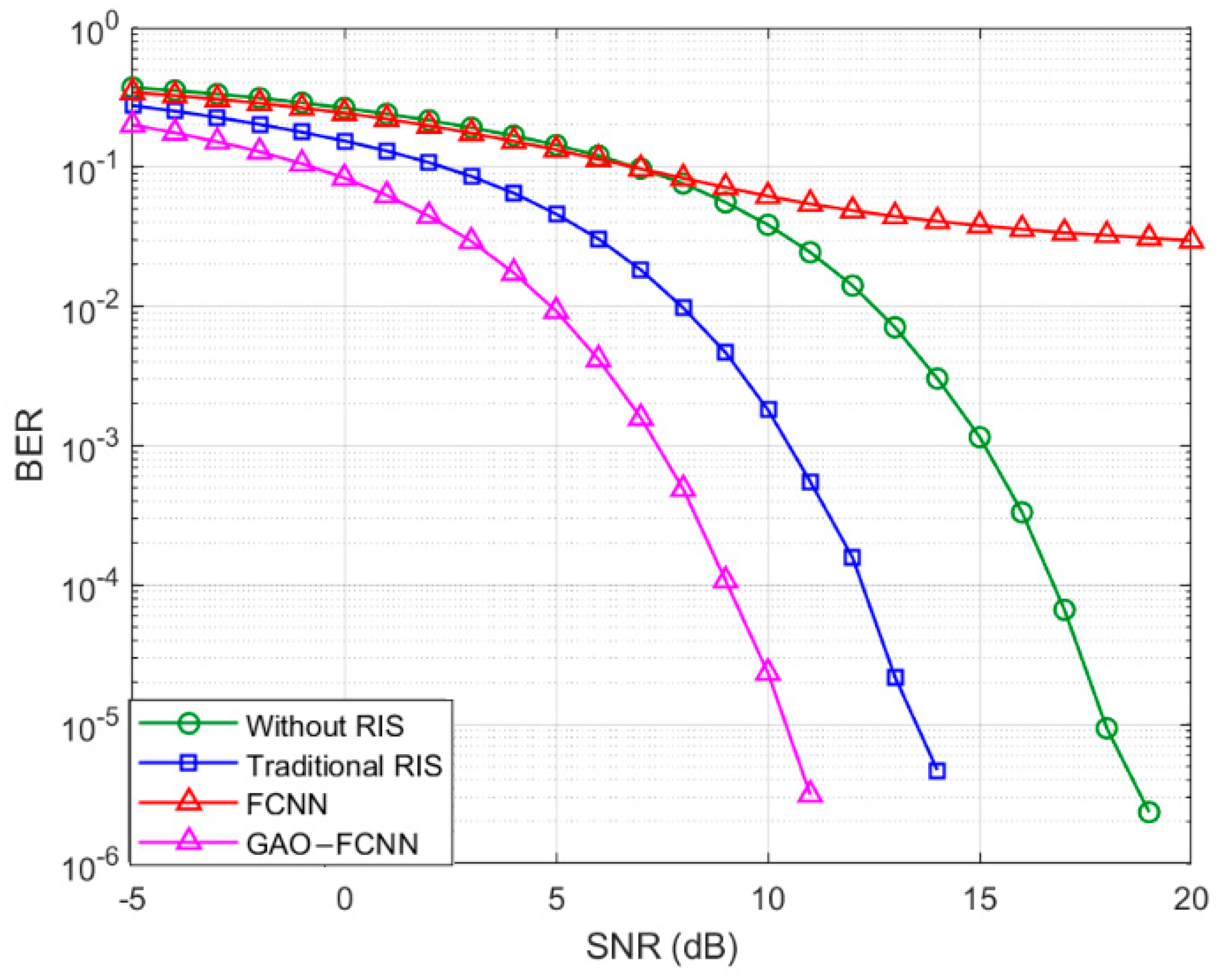
As illustrated in Figure 3, the curves of BER performance versus values of SNRs are investigated in an intelligent MIMO communication system without an RIS, an RIS–assisted intelligent communication system, an RIS–assisted intelligent communication system with an FCNN, and an RIS–assisted intelligent communication system using the proposed GAO–FCNN algorithm when d = 20 m. The green line means the MIMO communication system without an RIS, and it is served as the baseline. The blue line demonstrates the improved BER performance of the MIMO intelligent system established with an RIS. The red line demonstrates an RIS–assisted intelligent MIMO system that utilizes the FCNN. And the pink line depicts the BER performance of the RIS–assisted intelligent communication system using the GAO–FCNN scheme. Specifically, the RIS–assisted intelligent communication system is performed using the GAO–FCNN algorithm. The performance curves show that all BER values of these three intelligent communication systems are decreased when the values of the SNR are increased. However, the BER results of the FCNN basically remain to be unchanged under different values of SNR. Although the RIS–assisted MIMO communication system is supported by the FCNN, it can be observed that the BER performance is still maintained in a poor condition. Notably, the high BER means that the data transmission quality of the system may not be efficient enough, thus the user experience and system reliability are affected. The GAO–FCNN–enabled beamforming performance of the RIS–assisted intelligent communication system is improved significantly in the entire value range of the SNR. When the value of BER is 0.001, the performance gain of the SNR is 3.1 dB compared with the RIS–assisted intelligent communication system. It can be achieved when there are 256 RIS elements established in the system. The whole results show that the signal processing of the RIS–assisted intelligent communication are effectively optimized using the proposed GAO–FCNN algorithm. Traditional methods are surpassed by it through the discovery of optimal network parameters. Additionally, BER spikes that arise from the reliance on neural networks are mitigated by it.
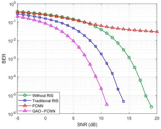
Figure 3.
BER performance versus different values of SNRs when d = 20 m.
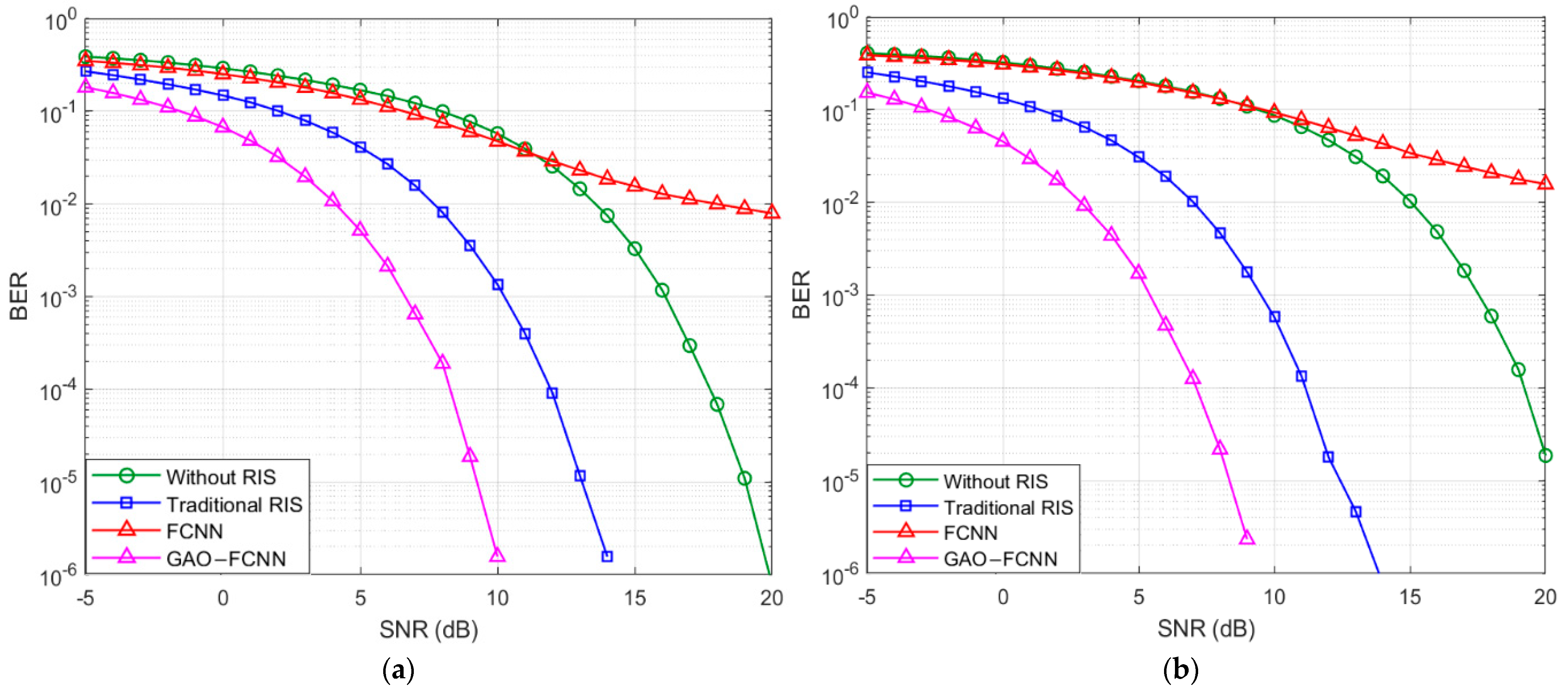
When d = 40 m, the performance curves in Figure 4 show that all BER values of four intelligent communication systems are decreased with the growth of the values of SNR. The overall BER performance curves are better than those when the distance is equal to 20 m in Figure 3. In addition, the BER result of the FCNN is still higher than that without RIS, specifically when the SNR is larger than 10 dB. It means that the system of the FCNN is not improved at a larger distance, while the BER performance of the remaining three systems can be optimized. Furthermore, it is concluded that the BER performance of the RIS–assisted intelligent communication using the GAO–FCNN algorithm is much better than the remaining three systems when d = 40 m. For an example, when the value of BER of the GAO–FCNN scheme is 0.001, the performance gain of the SNR is around 2.8 dB compared with the RIS–assisted intelligent communication system. Figure 4 depicts shows the BER performance curves of four intelligent communication systems when d = 60 m. When the value of the BER using the GAO–FCNN scheme is 0.001, the performance gain of the SNR is about 3.7 dB compared with the RIS–assisted intelligent communication system. Based on the above analysis, it can be concluded that the BER performance is affected by the length of the distance in the RIS–assisted wireless communication system.
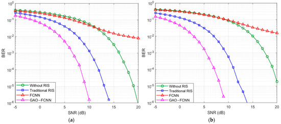
Figure 4.
BER performance versus different values of SNRs. (a) BER performance when d = 40 m. (b) BER performance when d = 60.
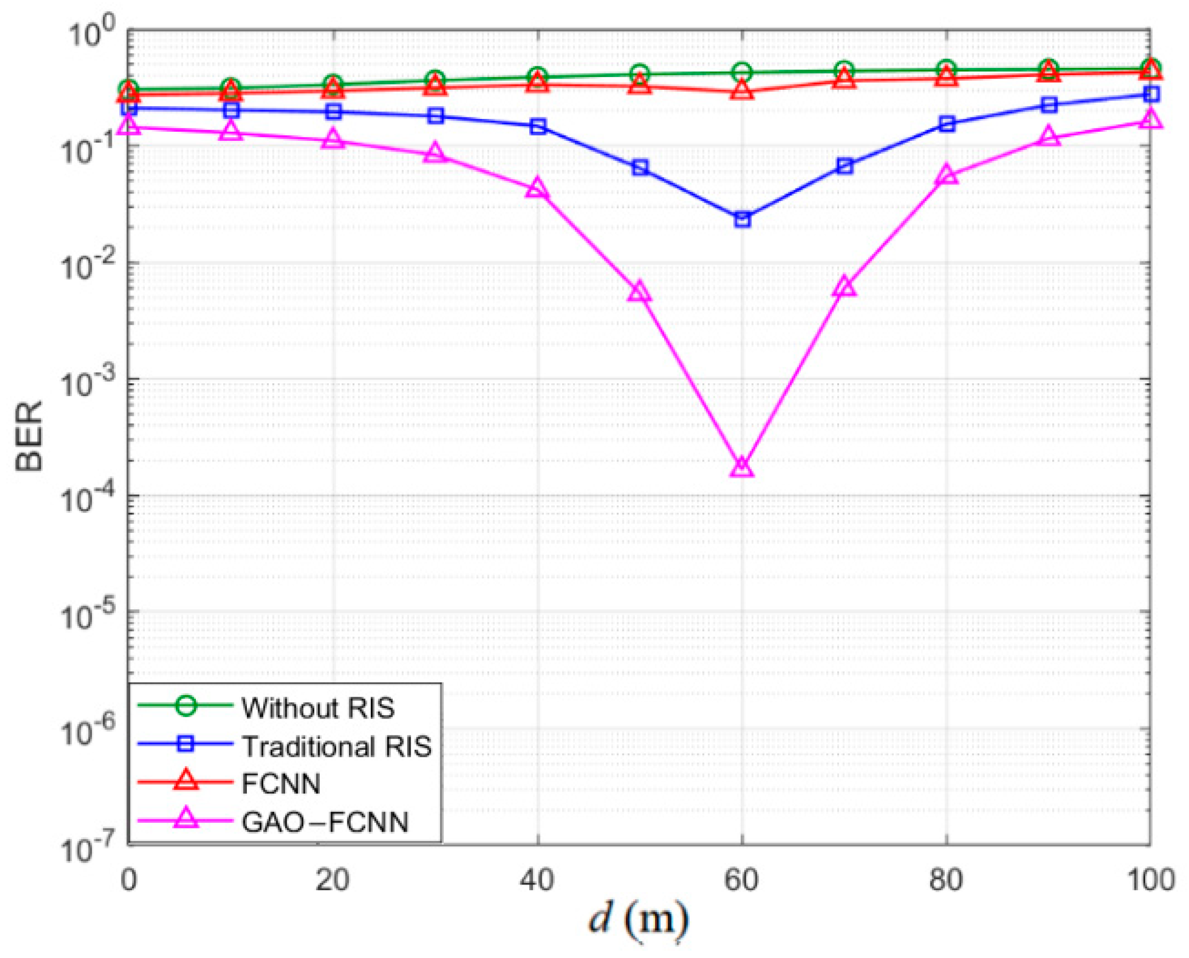
Figure 5 displays the BER performance versus the user movement distance d when SNR is equal to 0 dB under four wireless communication system scenarios. The green line represents the traditional intelligent MIMO system without an RIS, the blue line is the BER curve of an RIS–assisted intelligent MIMO system, the red line depicts the BER performance of an RIS–assisted MIMO intelligent system enhanced with the FCNN, and the pink line illustrates the BER values of an RIS–assisted intelligent communication system with the GAO–FCNN algorithm. In the system without the RIS, it appears that the BER values almost remain unchanged with the increasing distance. And it is worth noting that the BER also remains basically unchanged with an increasing distance in the system utilizing the FCNN. The reason may be due to the limitations or performance bottlenecks of the FCNN in signal transmission, resulting in the inability of error correction. The BER performance could potentially be limited by this situation, and the reliability and stability of data transmission are both influenced. Then the BER performance of the RIS–assisted intelligent communication system with GAO–FCNN is gradually improved with the increasing distance. It can be reached at the lowest value under the condition that the distance is equal to 60 m, and then it is gradually increased. It is also shown that the BER curves of the RIS–assisted intelligent communication system using the proposed GAO–FCNN algorithm is better than these three compared communication systems with different methods. However, in the RIS–assisted MIMO system and the GAO–FCNN–enhanced RIS–assisted MIMO intelligent system, a decreasing trend of the BER value is shown firstly at the distance of 60 m. After then, the BER value is increased with the growth of distance. Within a certain distance, the RIS technology can reflect, focus, or adjust the transmission path of the signal, thus significantly increasing the strength of the reliever signal, reducing the impact of interference and noise, and then leading to a prominent reduction in the BER. However, as the distance increases, the signal suffers from the severe fading of free–space propagation. Consequently, the signal strength is gradually decreased, and the performance of the BER is also deteriorated.
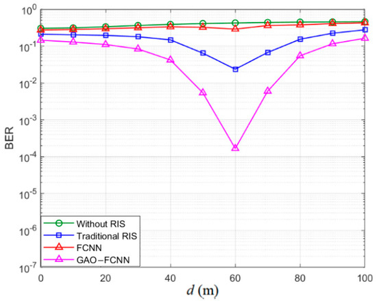
Figure 5.
BER performance versus the distance d when SNR = 0 dB.
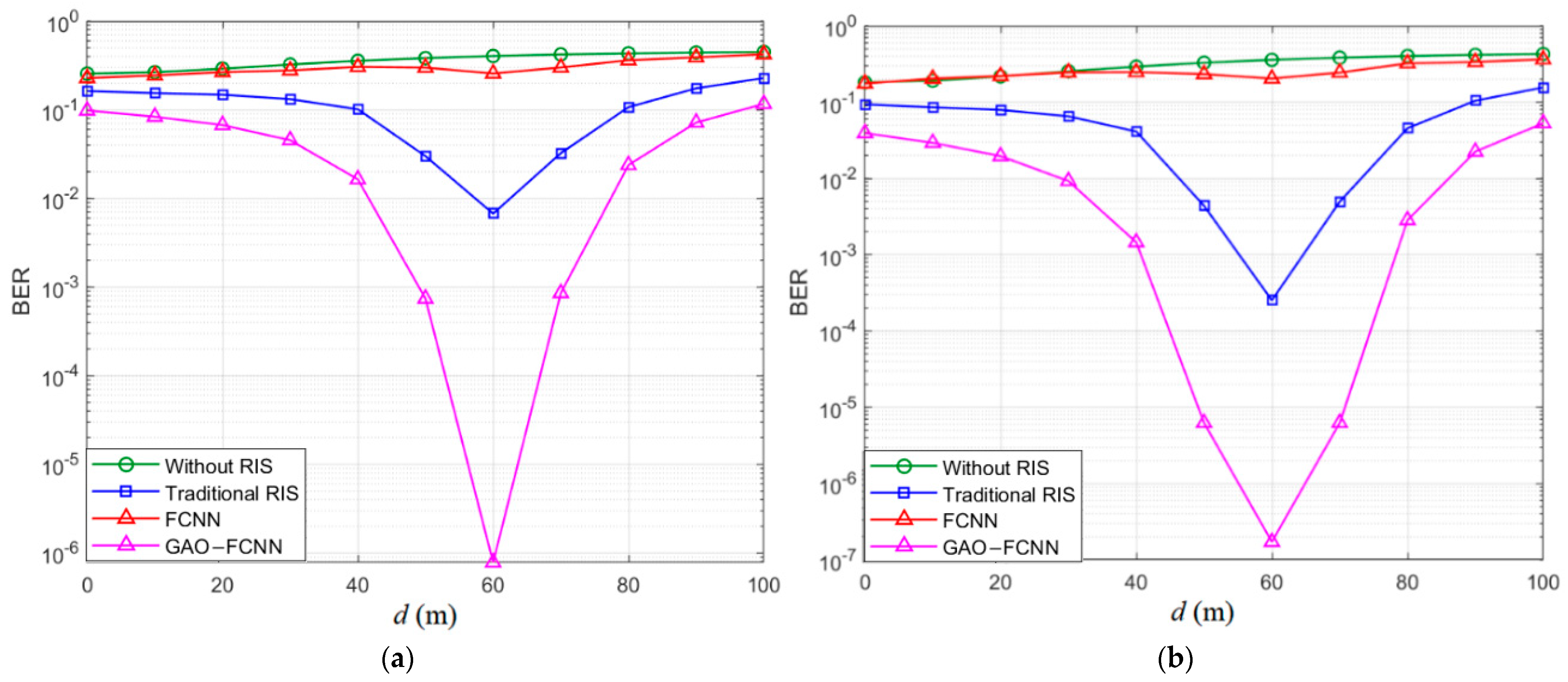
The BER performance versus the distance when the SNR = 5 dB and 10 dB are illustrated in Figure 6. As expected, the BER curves of the RIS–assisted intelligent communication system using the proposed GAO–FCNN algorithm is better than those three compared communication systems with different methods. As a consequence, the satisfactory BER performance of our proposed technique can be achieved under different values of the SNR even when d is changed very often.
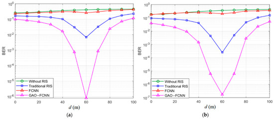
Figure 6.
BER performance versus the distance. (a) BER performance when SNR = 5 dB. (b) BER performance when SNR = 10 dB.
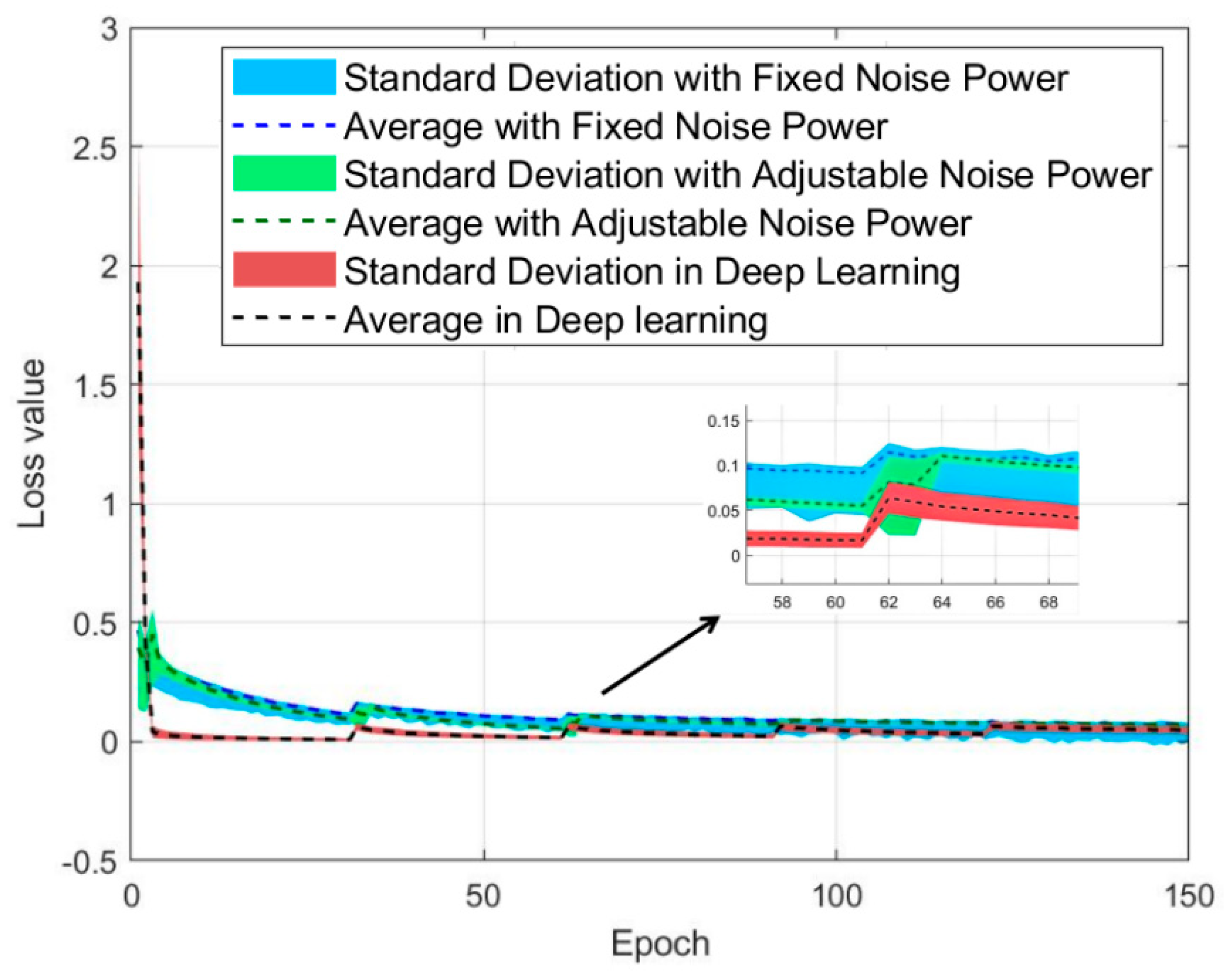
As illustrated in Figure 7, the RIS–assisted intelligent communication system is trained using the GAO–FCNN algorithm when the SNR is 6 dB. In the blue part, the system is maintained at the fixed noise power levels for both the standard deviation and the mean, the green part features the adjustable noise power settings of different parameters, and the red part represents dynamic adjustments of the standard deviation and the mean. As the training period is progressed, the loss value of the optimized learning is decreased rapidly at first, then more gradually, and the optimal performance at epoch 64 is ultimately achieved. To prevent an increasement of loss values, the corresponding optimization strategy is stopped when the training process is reached at 64 epochs. In comparison to the two learning methods (i.e., the fixed noise power and the adjustable noise power), the optimized learning is converged to the expected performance in just nine cycles, although it is started with a higher loss value. That is to say, only when the smaller standard deviations and faster training speeds are obtained, then the stable results can be remained. In the RIS–assisted wireless communication system, the BER performance can be effectively optimized by training the GAO–FCNN algorithm. The system performance can be gradually improved by adjusting noise power levels. And the parameters can be adjusted dynamically during the whole training process. Finally, attention should be paid to satisfy the size of the standard deviation and the training speed should be ensured to obtain stable results.
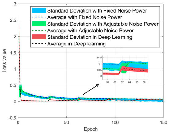
Figure 7.
The loss value of different training methods.
5. Conclusions
This paper focuses on the study of effectively solving the problem of BER optimization of joint beamforming in the RIS–assisted intelligent communication system. A hybrid optimization strategy of GAO–FCNN is proposed to realize the intelligent collaborative tuning of system parameters and to avoid convergence of the local optimum. Numerical results demonstrate significant SNR gains when compared to the other RIS–assisted intelligent communication systems. In future practical applications, more investigations should be performed to the optimization learning of the broadband multi–user RIS–assisted system.
Author Contributions
Conceptualization, K.C.; methodology, K.C.; software, K.C.; validation, T.L. and X.W.; formal analysis, T.L.; investigation, K.C. and X.W.; resources, K.C.; data curation, K.C.; writing—original draft preparation, K.C.; writing—review and editing, T.L. and X.W.; visualization, K.C.; supervision, K.C. and T.L.; project administration, K.C. and T.L. All authors have read and agreed to the published version of the manuscript.
Funding
This research was funded by NSFC (62101274) and Jiangsu NSF (BK20210640).
Data Availability Statement
Data are contained within the article.
Acknowledgments
The authors would like to thank all authors of their fundings.
Conflicts of Interest
The authors declare no conflicts of interest.
References
- Basar, E. Reconfigurable intelligent surface–empowered MIMO systems. Natl. Sci. Rev. 2023, 10, nwad096. [Google Scholar] [CrossRef]
- Jiang, H.; Mukherjee, M.; Zhou, J.; Lloret, J. Channel modeling and characteristics analysis for 6G wireless communications. IEEE Netw. 2021, 35, 296–303. [Google Scholar] [CrossRef]
- Guo, H.; Liang, Y.C.; Chen, J.; Larsson, E.G. Weighted sum–rate maximization for intelligent reflecting surface enhanced wireless networks. In Proceedings of the 2019 IEEE Global Communications Conference (GLOBECOM), Waikoloa, HI, USA, 9–13 December 2019; IEEE: Piscataway, NJ, USA, 2020. [Google Scholar] [CrossRef]
- Li, S.; Duo, B.; Yuan, X.; Liang, Y.C.; Renzo, M.D. Reconfigurable intelligent surface assisted UAV communication: Joint trajectory design and passive beamforming. IEEE Wirel. Commun. Lett. 2020, 9, 716–720. [Google Scholar] [CrossRef]
- Chang, D.; Jiang, H.; Zhou, J.; Zhang, H.; Mukherjee, M. Capacity optimization using augmented Lagrange method in intelligent reflecting surface–based MIMO communication systems. China Commun. 2020, 17, 123–138. [Google Scholar] [CrossRef]
- Zhou, Q.; Gong, Y.; Nallanathan, A. Radar–assisted beam selection in MIMO communication systems: A federated transfer learning approach. IEEE Trans. Veh. Technol. 2024, 73, 12172–12177. [Google Scholar] [CrossRef]
- Wu, Q.; Zhang, R. Intelligent Reflecting Surface Enhanced Wireless Network via Joint Active and Passive Beamforming. IEEE Trans. Wirel. Commun. 2019, 18, 5394–5409. [Google Scholar] [CrossRef]
- Zhang, S.; Zhang, R. Capacity Characterization for Intelligent Reflecting Surface Aided MIMO Communication. IEEE J. Sel. Areas Commun. 2020, 38, 1823–1838. [Google Scholar] [CrossRef]
- Chen, Z.; Guo, Y.; Zhang, P.; Jiang, H.; Xiao, Y.; Huang, L. Physical layer security improvement for hybrid RIS–assisted MIMO communications. IEEE Commun. Lett. 2024; early access. [Google Scholar] [CrossRef]
- Bao, H.; Fang, J.; Chen, Z.; Li, H.; Li, S. An efficient bayesian PAPR reduction method for OFDM–based massive MIMO systems. IEEE Trans. Wirel. Commun. 2016, 15, 4183–4195. [Google Scholar] [CrossRef]
- Ye, J.; Guo, S.; Alouini, M.-S. Joint Reflecting and Precoding Designs for SER Minimization in Reconfigurable Intelligent Surfaces Assisted MIMO Systems. IEEE Trans. Wirel. Commun. 2020, 19, 5561–5574. [Google Scholar] [CrossRef]
- Yan, Y.; Wang, Y.; Ni, W.; Niyato, D. Joint beamforming design for multi–functional RIS–assisted uplink communications. IEEE Commun. Lett. 2023, 27, 2697–2701. [Google Scholar] [CrossRef]
- Zhang, L.; Wu, D.; Zhao, M.J.; Nan, H. Uncertainty relation and the constrained quadratic programming. Phys. Scr. 2024, 99, 065103. [Google Scholar] [CrossRef]
- Dang, D.C.; Friedrich, T.; Kötzing, T.; Krejca, M.S.; Lehre, P.K.; Oliveto, P.S.; Sudholt, D.; Sutton, A.M. Escaping local optima using crossover with emergent diversity. IEEE Trans. Evol. Comput. 2018, 22, 484–497. [Google Scholar] [CrossRef]
- Fedorenko, V.A.; Sorokina, K.O.; Giverts, P.V. Multigroup classification of firing pin impressions with the use of a fully connected neural network. Program. Comput. Soft. 2024, 50, 73–84. [Google Scholar] [CrossRef]
- Muñoz, A.; Rubio, F. Evaluating genetic algorithms through the approximability hierarchy. J. Comput. Sci. 2021, 53, 101388. [Google Scholar] [CrossRef]
- Li, M.; Bouanani, F.E.; Tian, L.; Chen, W.; Han, Z.; Muhaidat, S. Error rate analysis of non-orthogonal multiple access with residual hardware impairments. IEEE Commun. Lett. 2021, 25, 2522–2526. [Google Scholar] [CrossRef]
- Cui, M.; Zhang, G.; Zhang, R. Secure wireless communication via intelligent reflecting surface. IEEE Wirel. Commun. Lett. 2019, 8, 1410–1414. [Google Scholar] [CrossRef]
- Gökceli, S.; Levanen, T.; Riihonen, T.; Renfors, M.; Valkama, M. Frequency–selective PAPR reduction for OFDM. IEEE Trans. Veh. Technol. 2019, 68, 6167–6171. [Google Scholar] [CrossRef]
- Dastoor, S.; Patel, H. Performance analysis of massive MIMO using various transmit precoding schemes for a wireless network. Int. J. Commun. Syst. 2024, 37, e5785. [Google Scholar] [CrossRef]
- Lipka, M.; Jarzyna, M.; Banaszek, K. Quantum Fingerprinting Over AWGN Channels with Power–Limited Optical Signals. IEEE J. Sel. Areas Commun. 2020, 38, 496–505. [Google Scholar] [CrossRef]
- Canbilen, A.E.; Basar, E.; Ikki, S.S. On the performance of RIS–assisted space shift keying: Ideal and non-ideal transceivers. IEEE Trans. Commun. 2022, 70, 5799–5810. [Google Scholar] [CrossRef]
- Singh, U.; Bhatnagar, M.R.; Bansal, A. RIS–assisted SSK modulation: Reflection phase modulation and performance analysis. IEEE Commun. Lett. 2022, 26, 1012–1016. [Google Scholar] [CrossRef]
- Xiong, B.; Zhang, Z.; Jiang, H.; Zhang, J.; Wu, L.; Dang, J. A 3D non-stationary MIMO channel model for reconfigurable intelligent surface auxiliary UAV–to–ground mmWave communications. IEEE Trans. Wirel. Commun. 2022, 21, 5658–5672. [Google Scholar] [CrossRef]
- Jiang, H.; Xiong, B.; Zhang, H.; Basar, E. Physics–Based 3D End-to-End Modeling for Double–RIS Assisted Non-Stationary UAV-to-Ground Communication Channels. IEEE Trans. Commun. 2023, 71, 4247–4261. [Google Scholar] [CrossRef]
- Jiang, H.; Xiong, B.; Zhang, H.; Basar, E. Hybrid Far- and Near-Field Modeling for Reconfigurable Intelligent Surface Assisted V2V Channels: A Sub–Array Partition Based Approach. IEEE Trans. Wirel. Commun. 2023, 22, 8290–8303. [Google Scholar] [CrossRef]
- Shi, W.; Jiang, H.; Xiong, B.; Chen, X.; Zhang, H.; Chen, Z.; Wu, Q. RIS–Empowered V2V Communications: Three-Dimensional Beam Domain Channel Modeling and Analysis. IEEE Trans. Wirel. Commun. 2024; early access. [Google Scholar] [CrossRef]
- Mao, K.; Zhu, Q.; Qiu, Y.; Liu, X.; Song, M.; Fan, W.; Kokkeler, A.B.J.; Miao, Y. A UAV–assisted Real–Time Channel Sounder for Highly Dynamic Nonstationary A2G Scenarios. IEEE Trans. Instrum. Meas. 2023, 72, 6504515. [Google Scholar] [CrossRef]
- Mao, K.; Zhu, Q.; Wang, C.-X.; Ye, X.; Gomez-Ponce, J.; Cai, X.; Miao, Y.; Cui, Z.; Wu, Q.; Fan, W. A Survey on Channel Sounding Technologies and Measurements for UAV–Assisted Communications. IEEE Trans. Instrum. Meas. 2024, 73, 8004624. [Google Scholar] [CrossRef]
- Wang, J.; Zhu, Q.; Lin, Z.; Chen, J.; Ding, G.; Wu, Q.; Gu, G.; Gao, Q. Sparse Bayesian Learning–Based Hierarchical Construction for 3D Radio Environment Maps Incorporating Channel Shadowing. IEEE Trans. Wirel. Commun. 2024, 23, 14560–14574. [Google Scholar] [CrossRef]
- Zeng, L.; Liao, X.; Xie, W.; Ma, Z.; Xiong, B.; Jiang, H. UAV-to-Ground Channel Modeling: (Quasi-)Closed–Form Channel Statistics and Manual Parameter Estimation. China Commun. 2023; accepted. [Google Scholar] [CrossRef]
Disclaimer/Publisher’s Note: The statements, opinions and data contained in all publications are solely those of the individual author(s) and contributor(s) and not of MDPI and/or the editor(s). MDPI and/or the editor(s) disclaim responsibility for any injury to people or property resulting from any ideas, methods, instructions or products referred to in the content. |
© 2024 by the authors. Licensee MDPI, Basel, Switzerland. This article is an open access article distributed under the terms and conditions of the Creative Commons Attribution (CC BY) license (https://creativecommons.org/licenses/by/4.0/).

