Article

Design and Modeling of Coreless Magnetoelectric Transducers for Snake-like Wave Energy Converters

1
Faculty of Automation, Huaiyin Institute of Technology, Huaian 223003, China
2
State Key Laboratory of Mechanics and Control of Mechanical Structures, Nanjing University of Aeronautics and Astronautics, Nanjing 210016, China
*
Author to whom correspondence should be addressed.
Electronics 2024, 13(20), 4092; https://doi.org/10.3390/electronics13204092
Submission received: 17 September 2024 / Revised: 12 October 2024 / Accepted: 14 October 2024 / Published: 17 October 2024
(This article belongs to the Section Power Electronics)

Abstract

:
With the development of the economy, people’s demand for energy is increasing, which has led to a shortage of fossil fuels. Wave energy is a widely distributed renewable energy source, and the development of wave energy generation technology can greatly alleviate the energy shortage problem. This study takes the snake-like wave energy converter (WEC) as an example and designs a coreless magnetoelectric transducer for it. The structure of the coreless magnetoelectric transducer is relatively simple, eliminating the iron core in the transducer, which can eliminate its own damping. At the same time, this structure can minimize the gap between the magnet and the coil, improve energy conversion efficiency, and work continuously under complex working conditions. This study takes two types of coreless magnetoelectric transducers as examples to analyze. This study aims to establish equivalent magnetic circuit models for the coreless magnetoelectric transducers, explore the effects of different magnets on the performance of the transducers, and optimize the parameters in the transducers. We used simulation software to analyze the transducer and verify the accuracy of the models. Finally, prototypes of the coreless magnetoelectric transducers were made, and a testing system for the transducer was established to test its energy conversion capability. Our experiments show that coreless magnetoelectric transducers have good energy conversion capabilities and can be used as transducers for snake-like WECs. At the same time, this type of transducer can also be applied to other types of WECs, providing a new approach for the research of WECs.

1. Introduction

With the development of society, people’s demand for energy is growing [1]. At present, the most commonly used energy is fossil energy, but it is non-renewable and will cause serious environmental problems. Therefore, developing renewable and clean energy technologies has become a hot spot of research nowadays [2]. Wave energy has a large energy flux density, and it is considered one of the most widely distributed renewable energy [3]. More importantly, wave energy can significantly promote the optimization of the energy structure and the achievement of emission reduction targets. Almost all major coastal countries have formulated policies to promote the development of wave energy. Reasonable development of wave energy can enable people in coastal areas to use cheaper electricity. The current wave energy generation technology generally requires three rounds of energy conversion, first converting wave energy into thermal energy, kinetic energy, chemical energy, bioenergy, and other forms of energy, then converting it into mechanical energy, and finally converting it into electrical energy through wave energy converter (WEC) [4].
With the deepening of experts’ research on WECs, various WECs have been designed and applied in commercial applications. There are several types of WECs, such as the point absorber [5,6,7], the raft WEC [8,9], the oscillating water column [10,11,12,13], or the duck WEC [14,15]. Waves drive these WECs in the ocean, driving the power take-off (PTO) system, which ultimately converts wave energy into electrical energy. Different types of PTO have different structures, which may consist of an air turbine, a hydraulic turbine, or a hydraulic motor.
In recent years, experts have conducted extensive research on the raft WEC. Jin et al. [16] introduced a physical and numerical experiment of a hinged raft WEC, utilizing the open-source tool WEC-Sim for modeling the hinged raft WEC, and discussed the effects of viscosity, submersion, overtopping, and wave steepness on the WEC. Abbasi et al. [17] discussed the establishment of a hydrodynamic model for a two-raft-type WEC using the boundary element method (BEM) and computational fluid dynamics (CFD) approaches. They identified the optimal values for linear and rotational hydraulic PTO damping and studied the impact of different diameter-to-length ratios, wave periods, and wave amplitudes. Zhao et al. [18] conducted an in-depth study on the impact of multi-degrees of freedom on the performance of a raft-type WEC. The results indicated that increasing the number of multi-degrees of freedom could enhance the efficiency of the WEC, particularly by coordinating the relative pitch and heave motions of the buoy. Chen et al. [19] proposed a novel hybrid control strategy for a raft-style WEC, which combines passive and active control strategies to enhance the wave energy capture performance of the WEC. Zhang et al. [20] proposed a novel rotary PTO with nonlinear stiffness for raft WECs, aiming to enhance capture efficiency and broaden the bandwidth. Research has found that bistable mechanisms can shift the resonance peak to a lower frequency range and reveal the phase control mechanism of nonlinear stiffness devices. Liu et al. [21] proposed a high-precise model of the hydraulic PTO for raft WECs. This model includes all necessary dynamic characteristics and adverse physical effects, such as pressure drop, flow leakage, flow resistance, and friction.
The point absorber WEC generally uses a permanent magnet linear generator (PMLG) as its PTO. Molla et al. [22] optimized the linear electrical generator (LEG) through finite element analysis to maximize the efficiency and power density of the LEG and observed its power generation, electrical performance, and magnetic performance under various conditions. Curto et al. [23] conducted an experimental comparative analysis on the application of ironless PMLGs in WEC systems by comparing prototypes that have the same geometry. The analysis through load tests indicated that the use of ironless machines in wave energy harvesting is justified, proving their effectiveness in collecting wave energy. Qiu et al. [24] proposed a novel three-phase tubular staggered transverse flux permanent magnet linear generator (TSTF-PMLG) for WECs, which features a simpler magnetic flux path, high mechanical strength, and low cogging force, making it more suitable for low-speed direct drive applications. Liu et al. [25] integrated a method combining the comprehensive sensitive parameters method with the entropy-based particle swarm optimization (EPSO) to optimize the PMLG. The experimental results indicate that the designed PMLG can be effectively applied to direct drive PTO systems.
The focus of this paper Is on a snake-like WEC, which is designed based on the raft WEC and the point absorber WEC. Compared to the raft WEC, its most important feature is the use of a magnetoelectric transducer as its PTO. The organization of this paper is as follows: in Section 2, the design of the snake-like WEC is introduced; in Section 3, the structure of the coreless magnetoelectric transducer is introduced, a model is established for it, and the model is used to optimize the transducer; in Section 4, the coreless magnetoelectric transducer is modeled using simulation software Comsol 5.3, two prototypes of the transducer are made to test their performance, and the results are compared with the conclusions drawn in Section 3; and in Section 5, the final conclusions are presented.

2. Design of the Snake-Like WEC

The design of the snake-like WEC is shown in Figure 1. The advantage of this WEC is that it can directly convert wave energy into electrical energy, reducing intermediate links and improving energy conversion efficiency. At the same time, its multi-buoy structure can be adapted to complex ocean conditions, facilitating large-scale commercial operations. The buoys are connected to each other through hinges, and their shape is cylindrical. One end of the multi-buoy structure is fixed to the seabed, while the other end is not fixed, which makes it able to adapt to different wave conditions. The relative motion of adjacent buoys drives the magnetoelectric transducer, thereby converting wave energy into electrical energy.

3. Design and Optimization of the Coreless Magnetoelectric Transducer

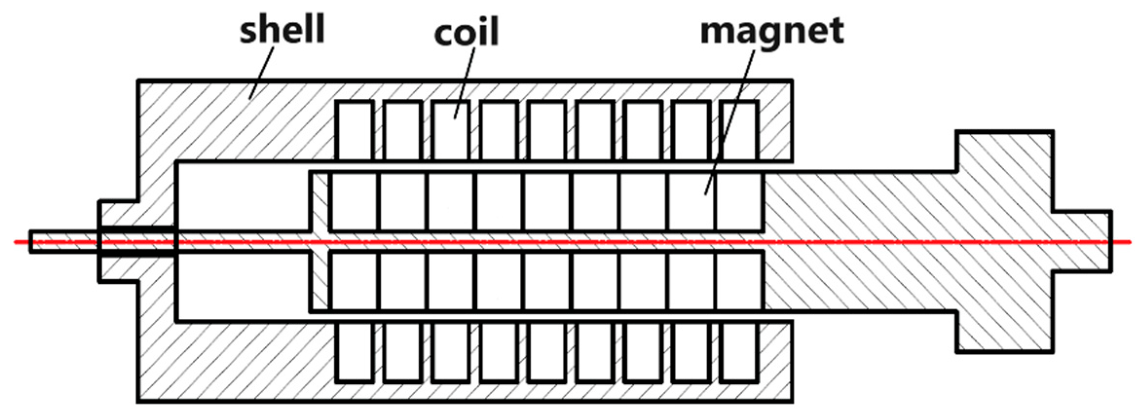
3.1. Design of the Coreless Magnetoelectric Transducer

The magnetoelectric transducer of the snake-like WEC is designed based on the linear generator. The diagram of the coreless magnetoelectric transducer is shown in Figure 2. The stator and rotor structures in the transducer are compact, and the permanent magnets and coil windings are tightly wound, which helps to convert the mechanical energy into electrical energy. Additionally, the iron core of the magnetoelectric transducer has been removed. Traditional magnetoelectric transducers contain magnets and iron cores inside, which inevitably attract each other and pose difficulties for the assembly of the transducer. This design can eliminate its own damping, reduce the gap between the magnet and the coil, and improve energy conversion efficiency, but the requirements for this magnet are relatively high. The coreless magnetoelectric transducer has a relatively simple structure and can operate continuously under complex working conditions. The shell of the coreless magnetoelectric transducer can be made of aluminum alloy, which solves the problem of the rusting of the shell and the iron core in seawater, making it easier to maintain compared to other transducer structures.
Ferrite magnets have the advantages of their low price, high cost-performance, excellent demagnetization resistance, and their lack of oxidation problems, but the comprehensive magnetic properties are poor. Alnico magnets have medium comprehensive magnetic properties and good oxidation and corrosion resistance. However, their coercive force is very low. Samarium cobalt magnets have medium comprehensive magnetic properties, their coercive force temperature coefficient is small, their Curie temperature is high, and they are able to oded, so they need to be plated during the production process, and they continue to replace other permanent magnets in many fields with high cost-performance. NdFeB permanent magnets have good comprehensive magnetic properties; however, they easily oxidize and corrode, so they need to be coated in the production process, and they are a cost-effective alternative to other permanent magnets in many fields. After making many comparisons and combining them with the practical application of the project, Neodymium magnet (NdFeB) N42 was selected as the permanent magnet.

3.2. Equivalent Magnetic Circuit Model of the Coreless Magnetoelectric Transducer

The main objective of this phase of the study was to optimize magnetoelectric transducers through modeling methods and obtain general rules in the optimization process. Evaluating the performance of magnetoelectric transducers is different from evaluating generators. This paper introduces the concept of maximum damping coefficient to evaluate the energy conversion capability of magnetoelectric transducers, which can also provide the theoretical basis for the control of WECs. In order to facilitate the modeling, it is necessary to assume that the magnetization curves of the magnetic materials are linear. Also, for ease of calculation and analysis, higher-order effects such as eddy currents and hysteresis are neglected.

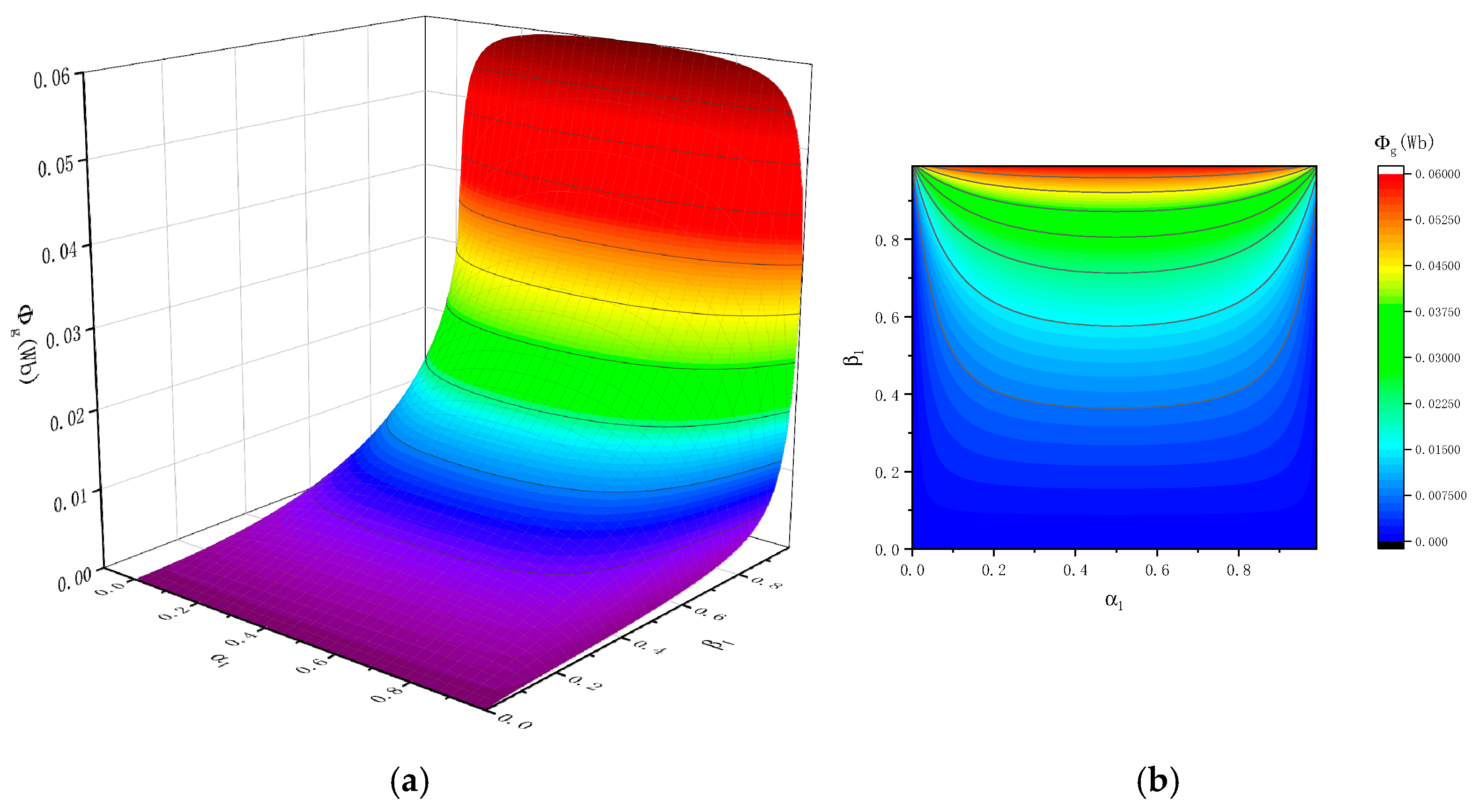
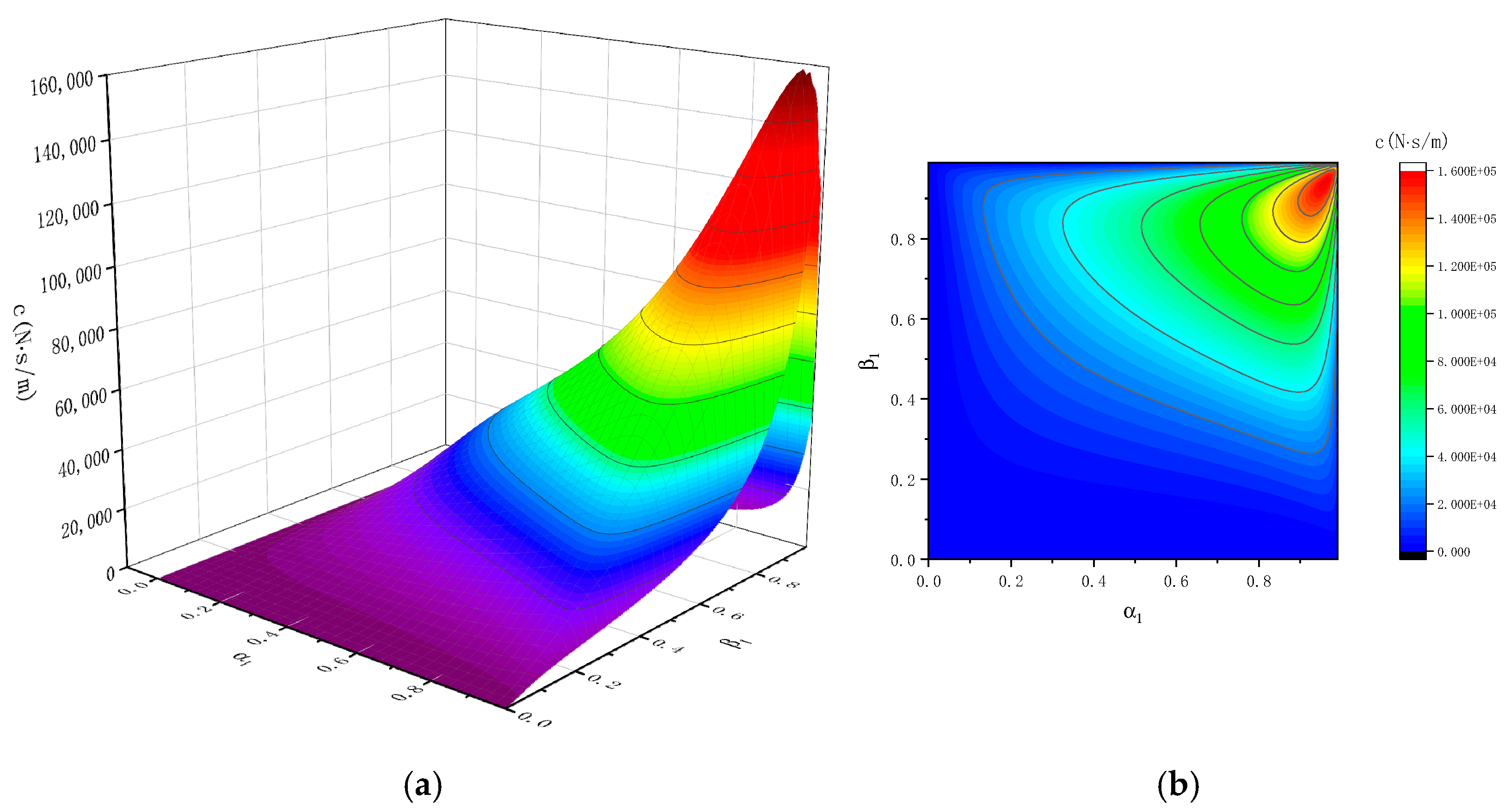
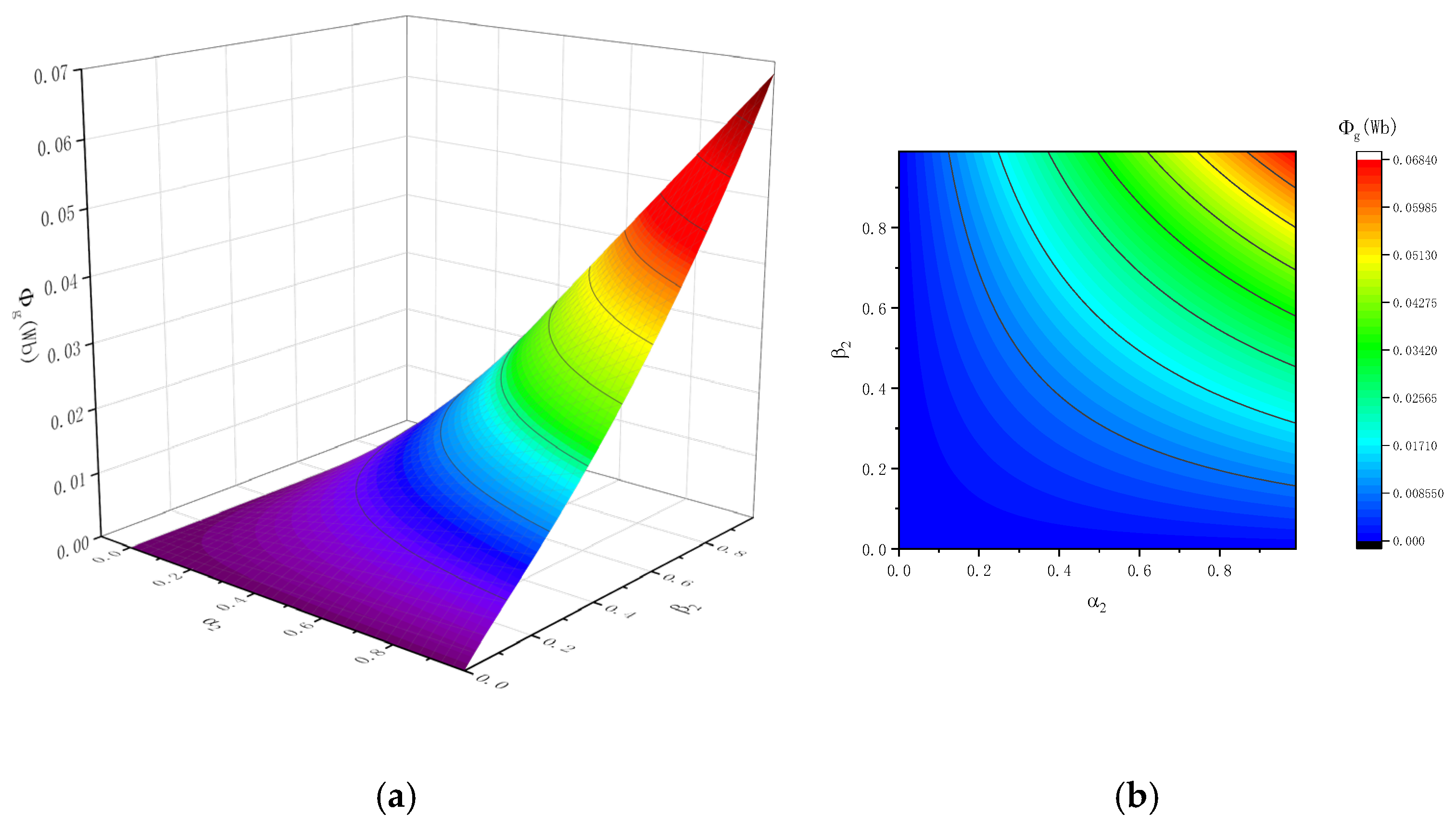
3.2.1. Equivalent Magnetic Circuit Model of the Coreless Magnetoelectric Transducer with Axial Permanent Magnets

Due to the cylindrical shape of the magnetoelectric transducer, we focus on discussing the half longitudinal section, as shown in Figure 3. In order to facilitate the establishment of its equivalent magnetic circuit model, the pole length of the magnet with yoke iron is τ, the thickness of the axial magnets is τma, the outer radius of the permanent magnets is rmo, the inner radius of the magnets is rmi, the outer radius of the coils is rco, and the inner radius of the coils is rci.
In the magnetic circuit analysis of the magnetoelectric transducer, one of the magnets was selected for analysis. Assuming the existence of a neutral plane for the magnet and the yoke iron, according to Kirchhoff’s second law of magnetic circuit:
H c τ m a = B r μ r μ 0 τ m a = R m + 2 R g Φ g
where Hc is the coercivity, Br is the remanence, μr is the relative permeability, μ0 is the vacuum permeability, and Φg is the magnetic flux of the air gap. Rm is the reluctance of the magnet, and Rg is the reluctance of the air gap.
The Rm and Rg can be expressed as:
R m = τ m a μ r μ 0 π r m o 2 r m o + r m i 2 2
R g = r c o r m o π μ 0 r c o + r m o τ τ m a 2
The magnetic flux of the air gap (Φg) is:
Φ g = B r τ m a μ r μ 0 R m + 2 R g = π B r τ m a τ m a r m o 2 r m o + r m i 2 2 + 4 μ r r c o r m o r c o + r m o τ τ m a
We define α1 as the thickness ratio of the axial permanent magnets and yoke iron:
α 1 = τ m a τ
We define β1 as the magnet-coil radial size ratio:
β 1 = r m o r m i r c o r m i
Assuming the pole length τ of the magnetization structure is 0.2 m, the inner radius rmi is 0.02 m, and the outer radius rco is 0.15 m, the Φg of the magnetoelectric transducer under different combinations of α1 and β1 can be obtained, as shown in Figure 4. Figure 4 shows that when α1 is constant, Φg will increase with the increase of β1. When β1 is constant, the maximum value of Φg is reached when α1 is 0.5.
The cylindrical surface area of the air gap in the magnetoelectric transducer with axial permanent magnets is:
S g = π 2 r c o + r m o τ τ m a
The structure of the transducer is compact, and assuming there is no leakage, the flux density of the air gap Bg can be expressed as:
B g = Φ g S g = 2 B r τ m a τ m a r c o + r m o τ τ m a r m o 2 r m o + r m i 2 2 + 4 μ r r c o r m o
The coil of the magnetoelectric transducer can reach the maximum damping coefficient c in the short-circuit state, and c can be calculated as:
c = 1 ρ Γ B g 2 d Γ = 2 r c o r c i S g B g 2 ρ
where Γ is the conductor volume and ρ is the resistivity of the coil wire metal. The material of the coil is generally copper and ρCu is 1.75 × 10⁻⁸ Ω·m.
The maximum damping coefficient c under different combinations of α1 and β1 conditions can be obtained, as shown in Figure 5. By comprehensively comparing the maximum damping coefficient c of the single coil of the magnetoelectric transducer, it can be found that when β1 remains constant, c will increase with the increase of α1, and then a turning point will appear when α1 is 0.9. Similarly, when α1 remains constant, c will increase with the increase of β1, and then a turning point will appear when β1 is 0.9. Therefore, by modeling and optimizing the transducer through an equivalent magnetic circuit model, it can be concluded that the maximum damping coefficient c of the coreless magnetoelectric transducer with axial permanent magnets is highest when α1 = 0.9 and β1 = 0.9.

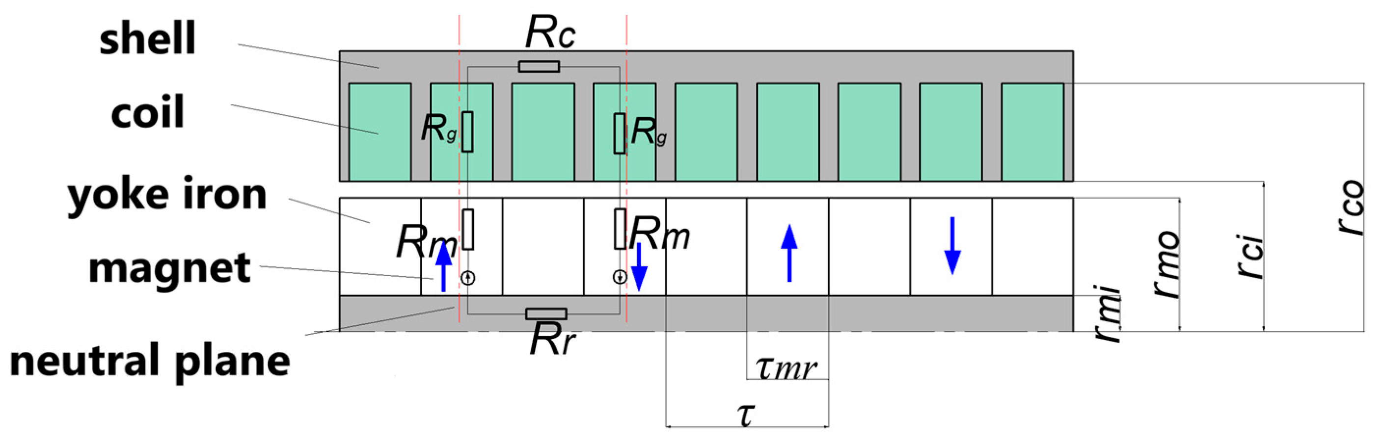
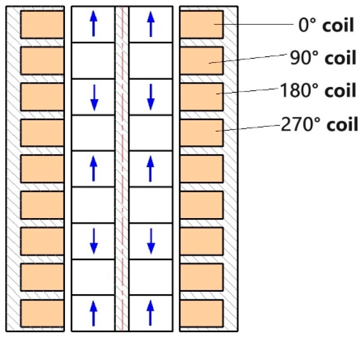
3.2.2. Equivalent Magnetic Circuit Model of the Coreless Magnetoelectric Transducer with Radial Permanent Magnets

Similar to the magnetoelectric transducer with axial permanent magnets, the magnetoelectric transducer with radial permanent magnets and its equivalent magnetic circuit are modelled as shown in Figure 6. The pole length of the magnet with yoke iron is τ and the thickness of the radial magnets is τmr.
The magnetic flux of the air gap (Φg) of the magnetoelectric transducer with radial permanent magnets is:
Φ g = π B r r m o r m i τ m r 2 r m o r m i r m o + r m i + 2 μ r r c o r m o r c o + r m o
We define α2 as the thickness ratio of the radial permanent magnets and yoke iron:
α 2 = τ m r τ
We define β2 as the magnet-coil radial size ratio:
β 2 = r m o r m i r c o r m i
Assuming the pole length τ of the magnetization structure is 0.2 m, the inner radius rmi is 0.02 m, and the outer radius rco is 0.15 m, the Φg of the magnetoelectric transducer under different combinations of α2 and β2 can be obtained, as shown in Figure 7. Figure 7 shows that Φg increases with the increase of α2 and β2. When α2 = 1 and β2 = 1, the value of Φg reaches its maximum.
The cylindrical surface area of the air gap in the magnetoelectric transducer with radial permanent magnets is:
S g = π r c o + β 2 r c o r m i + r m i α 2 τ 2
The flux density of the air gap is:
B g = Φ g S g = B r r m o r m i r m o r m i r c o + r m o r m o + r m i + μ r r c o r m o
According to Equation (9), the c of the magnetoelectric transducer with radial permanent magnets can be obtained as shown in Figure 8. It can be observed from Figure 8 that when β2 remains constant, c increases with the increase of α2 and reaches its maximum value when α2 is 1. When α2 remains constant, the maximum value of c appears when β2 is 0.65.

4. Results and Discussions

4.1. Simulation of the Coreless Magnetoelectric Transducer

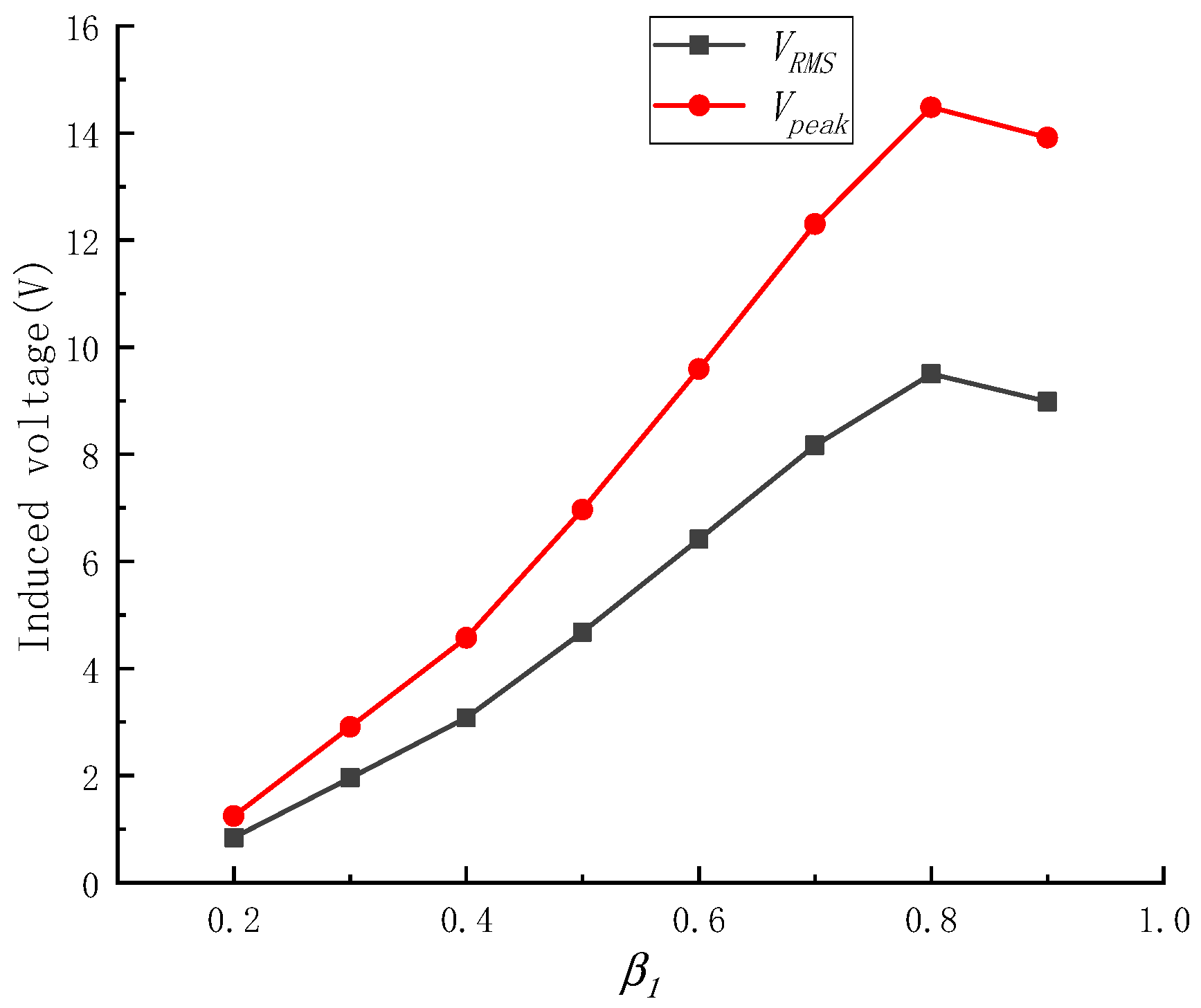
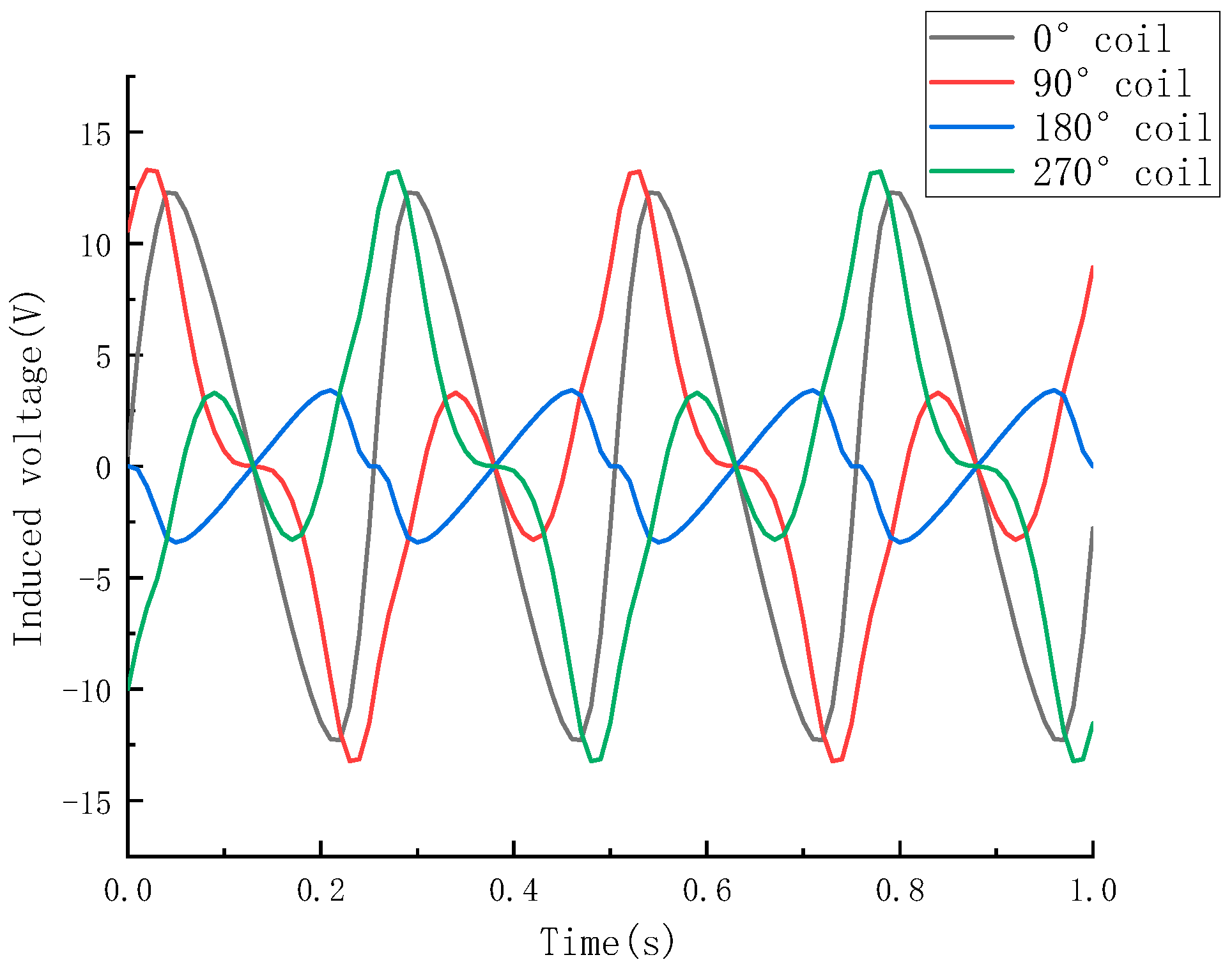
4.1.1. Simulation of the Coreless Magnetoelectric Transducer with Axial Permanent Magnets

As seen in Section 3.2, the external dimensions of the magnetoelectric transducer remain consistent. We established the finite element model of the coreless magnetoelectric transducer using COMSOL Multiphysics 5.3. To simplify the model, the 3D model of the magnetoelectric transducer was obtained by rotating the figure in Figure 9 around the z-axis. The arrows in Figure 9 represent the magnetic field distribution of the magnetoelectric transducer. In the simulation software, the size of the grid was set to 0.1 mm due to the smoother voltage profile obtained with this setting.
In this experiment, the coil was made of enameled wire with a diameter of 2 mm, so the number of turns of a single coil could be approximately expressed as:
N = π 2 3 S c S w = S c d 2
According to Equation (15), the number of turns of the coil could be calculated as shown in Table 1.
When modeling the coreless magnetoelectric transducer with axial permanent magnets under different α1 conditions, it was assumed that β1 = 0.6 and the relative velocity between the mover and the stator was 0.1 m/s. The simulated peak voltage value (Vpeak) and the effective voltage value (VRMS) are shown in Figure 10. Figure 10 shows that the Vpeak and the VRMS of a single coil vary with the condition of α1. The maximum voltage value was reached at α1 of 0.9, where the Vpeak was 9.59 V and the VRMS was 6.42 V.
Using the same method, assuming α1 = 0.9, the single-coil Vpeak and VRMS of the coreless magnetoelectric transducer with axial permanent magnets under different β1 conditions are shown in Figure 11. The maximum voltage value was reached at a β1 of 0.8, where the Vpeak was 14.48 V and the VRMS was 9.50 V.
We compared the results of the equivalent magnetic circuit model with the results of the finite element analysis. After optimizing the equivalent magnetic circuit model, we found that the α1 and β1 of the magnetoelectric transducer were 0.9 and 0.8, which is roughly consistent with the finite element analysis results, which showed that α1 and β1 were 0.8. The modeling results of the equivalent magnetic circuit model are good.
After comparison, we found that the results of the equivalent magnetic circuit model (α1 = 0.9, β1 = 0.9) were roughly consistent with the finite element analysis results (α1 = 0.9, β1 = 0.8), proving that the modeling results of the equivalent magnetic circuit model were effective.
Due to the fact that each permanent magnet array consists of four magnetic and iron rings, in order to maximize the output voltage of the magnetoelectric transducer during small movements, the coils were designed to correspond one-to-one with the magnet as shown in Figure 12. Each set of coils contains a 0°, 90°, 180°, and 270° coil. Among them, the magnitude of voltage in the 0° coil and the 180° coil was the same, but the direction was opposite. For the same reason, the magnitude of voltage in the 90° coil was the same as that of the 270 ° coil, but in opposite directions. Therefore, in subsequent analyses, 0° and 180° coils were set in opposite directions to form winding A, and 90° and 270° coils were set in opposite directions to form winding B. The open circuit voltage waveform of the two windings of the magnetoelectric transducer with axial permanent magnets is shown in Figure 13.

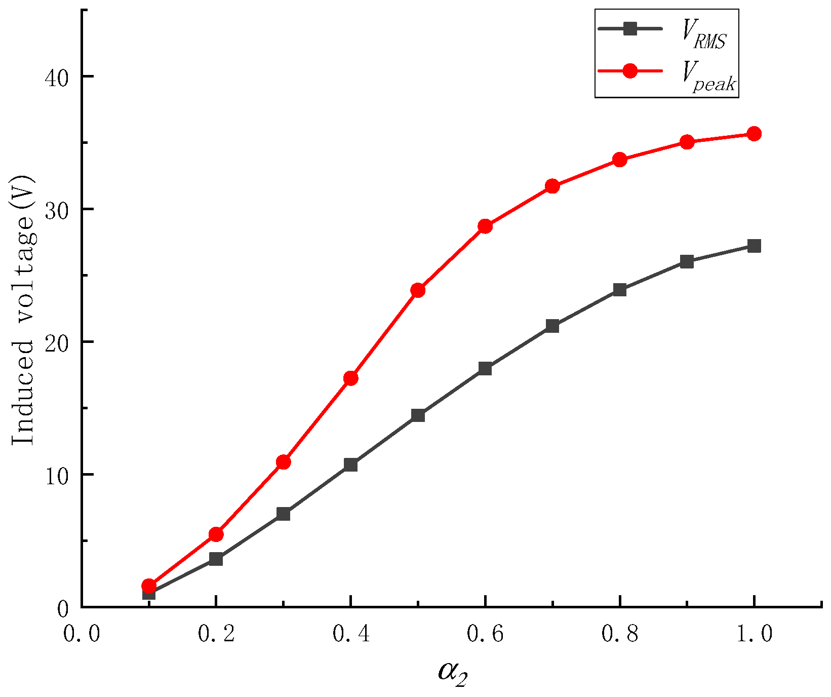
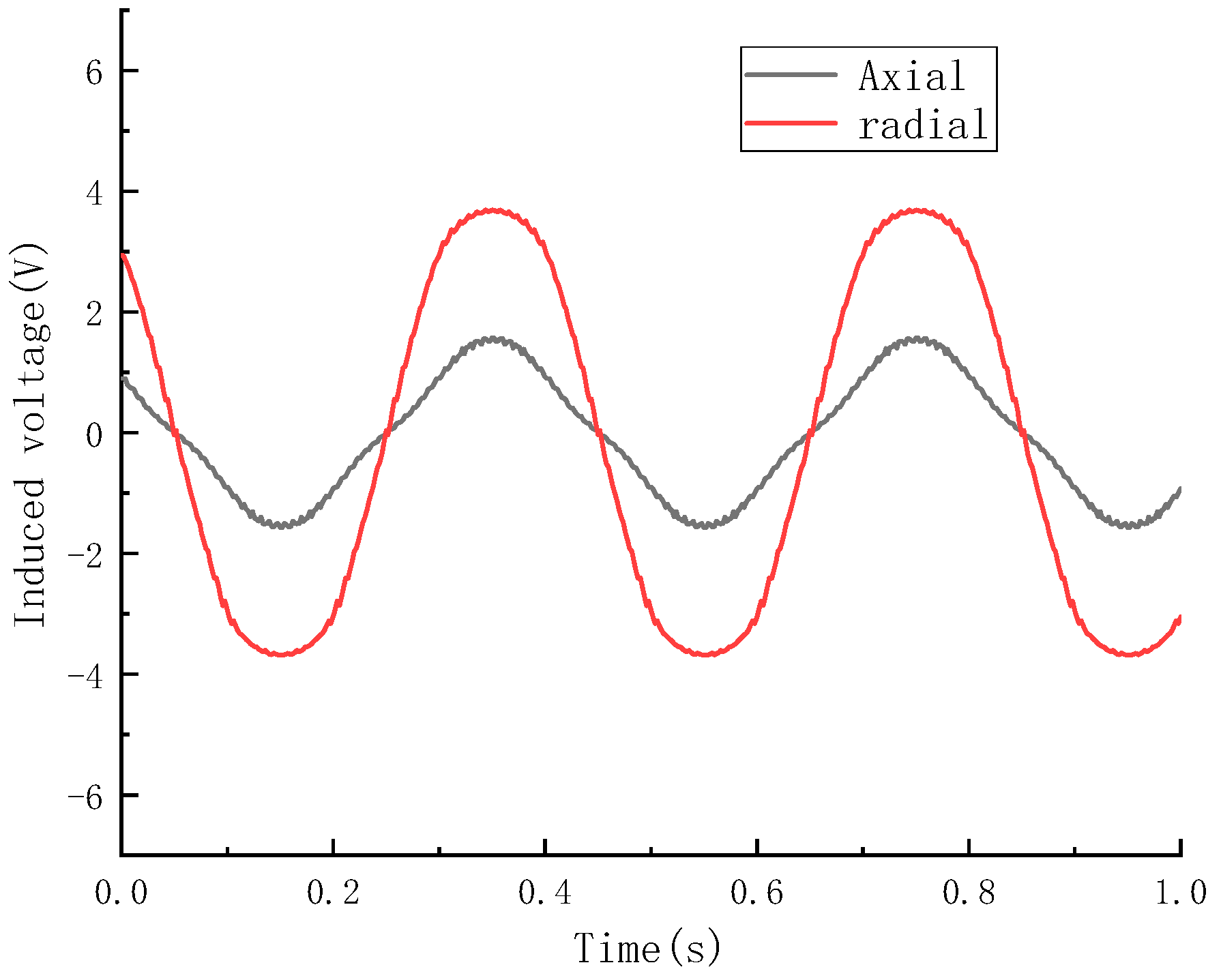
4.1.2. Simulation of the Coreless Magnetoelectric Transducer with Radial Permanent Magnets
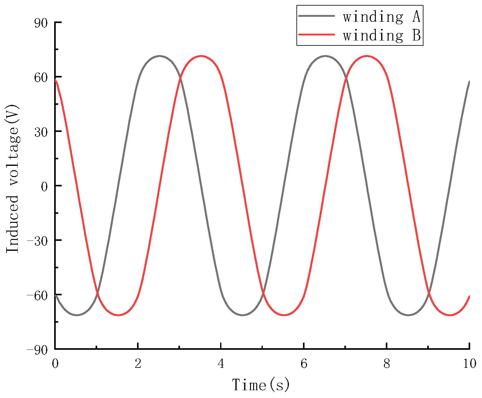
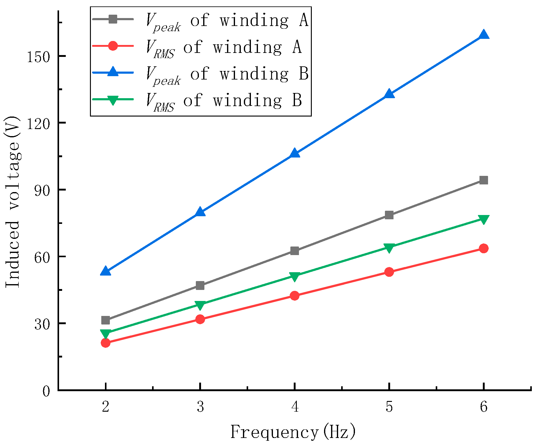
We conducted a finite element analysis of the coreless magnetoelectric transducer with radial permanent magnets using the same approach as described earlier. Assuming β2 = 0.6, finite element models of the magnetoelectric transducer for different α2 conditions were performed using COMSOL. The Vpeak and the VRMS under different α2 conditions are shown in Figure 14. Figure 14 shows that the maximum voltage value was reached at α2 of 1, where the Vpeak was 35.66 V and the VRMS was 27.23 V. The magnetic field distribution of the magnetoelectric transducer with radial permanent magnets is shown in Figure 15.
Assuming α2 = 1, the single-coil Vpeak and VRMS of the coreless magnetoelectric transducer with radial permanent magnets under different β2 conditions are shown in Figure 16. The maximum voltage value was reached at a β2 of 0.6. We found that the results of the equivalent magnetic circuit model (α2 = 1, β2 = 0.65) were roughly consistent with the finite element analysis results (α2 = 1, β2 = 0.6). Under these conditions, the open circuit voltage waveform of the two windings of the magnetoelectric transducer with radial permanent magnets is shown in Figure 17.

4.1.3. Comparison

Comparing the simulation results of the two types of coreless magnetoelectric transducers, it could be concluded that due to the different magnets, their internal structures are also different. The modeling results are shown in Table 2.
The table shows that the equivalent magnetic circuit model has good modeling results for both transducers. The comparison of the results reveals that the energy conversion ability of the coreless magnetoelectric transducer with radial permanent magnets is stronger than that of the other, and its open circuit voltage is higher. Therefore, in general, this transducer can be chosen as part of the snake-like WEC. However, it cannot be ignored that radial permanent magnets are expensive to produce, about ten times more than axial magnets, and their stability has yet to be proven. Additionally, radial magnets are made of multiple magnets spliced together, and the stability of their operation in the ocean has yet to be verified. Therefore, in situations where costs need to be kept under tight control and in areas where wave energy is not particularly abundant, coreless magnetoelectric transducers with axial magnets can be used.

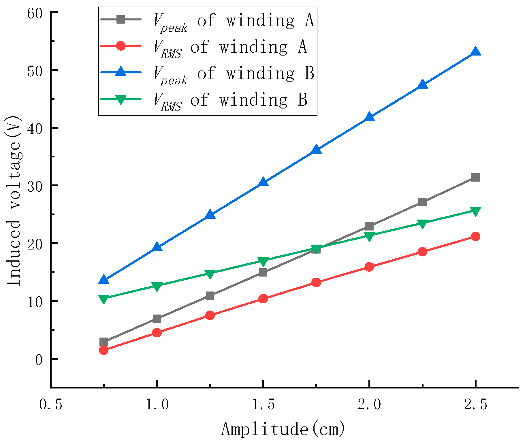
4.2. Experimental Study

In this phase of the study, we produced two prototypes of the transducer and tested them to verify the accuracy of the model. In order to test the performance of the prototypes, we customized a testing system for the prototypes, as shown in Figure 17. The test system consists of a vibration test table (Su Shi DL-300-40), an oscilloscope (Tectronic TDS 2012), an acceleration sensor, and the supporting structure of the prototypes. Due to the limitations of the testing site, the WEC cannot be directly produced for testing, and the prototypes of the transducer need to be scaled down proportionally. The prototype is shown in Figure 18.
Since the size of the prototype was reduced, the transducer needed to be re-modeled and optimized for the actual situation and dimensional conditions. The dimensions of the magnetoelectric transducers were determined by the previous calculations, as shown in Table 3. From the simulation results, it could be found that the values of α and β changed because of the reduced size of the prototype, but they were approximately the same as before the reduction. In this study, two prototypes were fabricated and tested, and the performance of these two prototypes was tested to compare their energy conversion capability, so the associated errors due to the reduction of the sample were not a concern of this study.
During the experiment, the mover of the prototype was fixed on the vibration table, and the motion speed of the vibration table was adjusted to a constant speed of 0.2 m/s. The speed was set to 0.2 m/s because the transducer normally operates at roughly 0.2 m/s, which makes it easy to compare with other transducers.
The single-coil-induced voltage of the prototypes is shown in Figure 19. Figure 19 shows that the waveform of the induced voltage of the prototype is basically consistent with the waveform of the induced voltage of the transducer in the simulation. The Vpeak of the single-coil-induced voltage of the prototype with axial permanent magnets was 2.78 V and the VRMS was 1.02 V. The Vpeak of the single-coil-induced voltage of the other prototype was 3.69 V and the VRMS was 1.57 V. These experimental results also matched the simulation results.
Since the motion trajectory of the transducer’s mover relative to the stator in WEC is generally a sine curve, the following analyses explored the effects of different amplitudes and frequencies on the output voltage of the transducer. We set the vibration frequency of the vibration table to 2 Hz and the amplitude to 25 mm and obtained the open circuit voltage waveforms of the four-phase coils in transducer prototypes, as shown in Figure 20 and Figure 21. These figures show that due to the different positions of the magnets corresponding to different coils, the voltage waveform of each coil was different.
The voltage waveforms and effective values output by winding A and winding B, which were composed of coils of different phases, were roughly the same.
The following tests were carried out on each of the two transducers to find out the relationship between the amplitude and frequency of the vibration table and the output voltage of the windings.

4.2.1. Prototype of the Coreless Magnetoelectric Transducer with Axial Permanent Magnets

Firstly, the prototype was tested at different vibration frequency conditions. The amplitude of the vibration table was set to 2.5 cm and the vibration frequencies were set to 2–6 Hz during the test. This is because the maximum amplitude of the vibration test system is 2.5 cm. The frequency was set to 2–6 hz, which covers the operating frequency of the transducer. The experimental results are shown in Figure 22. Figure 22 shows that as the frequency of the vibration table increased, the winding voltage of the transducer prototype also increased, and there was a linear relationship between the two. It could also be observed that although the peak values of the two windings were different, their effective values were close. When the vibration frequency was 6 Hz, the Vpeak of winding A was 29.74 V and its VRMS was 14.40 V, and the Vpeak of winding B was 20.96 V and its VRMS was 13.87 V.
Secondly, the prototype was tested at different vibration amplitude conditions to obtain the peak and effective values of the winding voltage. The frequency of the vibration table was set to 2 Hz and the amplitudes were set to 0.75–2.5 cm. The experimental results are shown in Figure 23. If the sine excitation of the vibration table is approximated as a uniform motion, the relative velocity between the stator and rotor of the transducer prototype can be approximated as 0.06 and 0.2 m/s, respectively. Figure 23 shows that as the amplitude of the vibration table increased, the winding voltage of the transducer prototype also increased. There is also a linear relationship between the two, which is consistent with the simulation results. It could also be observed that as the amplitude increased, the difference between the voltages of the two windings would narrow, and when the amplitude was large enough, the voltage of the two windings would become the same. When the vibration amplitude was 2.5 cm, the Vpeak of winding A was 9.94 V and its VRMS was 4.76 V, and the Vpeak of winding B was 7.18 V and its VRMS was 4.67 V.

4.2.2. Prototype of the Coreless Magnetoelectric Transducer with Radial Permanent Magnets

The method to test this prototype was almost the same as that of the previous prototype. Firstly, the amplitude of the vibration table was set to 2.5 cm and the vibration frequencies were set to 2–6 Hz during the test. The experimental results are shown in Figure 24. It could be seen that the relationship between winding voltage and vibration frequency was approximately the same for both prototypes. But it also could be seen that the output voltages of the prototype of the coreless magnetoelectric transducer with radial permanent magnets were much higher than those of the other prototype. When the vibration frequency was 6 Hz, the Vpeak of winding A was 94.18 V and its VRMS was 63.60 V, and the Vpeak of winding B was 159.22 V and its VRMS was 77.08 V.
The frequency of the vibration table was set to 2 Hz, and the amplitudes were set to 0.75–2.5 cm. The experimental results are shown in Figure 25. When the vibration amplitude was 2.5 cm, the Vpeak of winding A was 31.39 V and its VRMS was 21.20 V, and the Vpeak of winding B was 53.07 V and its VRMS was 25.69 V.
The winding voltages of the two prototypes at different frequencies are shown in Table 4. From the data in the table, it can be seen that, in general agreement with the modeling results and the simulation results, the energy conversion capability of the prototype with radial permanent magnets is stronger than that of the other prototype.
Zhang et al. [26,27] designed two tubular linear motors, and when the movable and stator of these two linear motors were operated at a relative speed of 0.4 m/s, the peak output voltages of the motors reached 45 V and 72 V, respectively. However, their prototype was larger and longer than the one in this study. The prototype with radial permanent magnets, under the movement conditions of 25 mm of amplitude and a frequency of 4 Hz, presented a peak voltage of the two coils of 62.79 V and 106.15 V, which shows that the coreless magnetoelectric transducer in the conversion is not weaker than the iron core motor, and the coreless magnetoelectric transducer has the advantages of its simple structure.
This also proves that the coreless design can be applied to the snake-like WEC, which is conducive to the popularization of the snake-like WEC. Compared to hydraulic devices, coreless magnetoelectric transducers have a simpler structure, are easier to maintain, have lower costs, can adapt to more harsh environments, and have better energy conversion capabilities. This study provides a new approach for the large-scale deployment of snake-like WECs.

5. Conclusions

This study provided an introduction to the snake-like WEC and designed a coreless magnetoelectric transducer for the snake-like WEC.
This type of transducer was designed for the actual conditions of the snake-like WEC, instead of directly using a linear motor. Due to the development of magnetic materials and their anti-corrosion technology, this magnetoelectric transducer eliminates the internal iron core in order to increase its internal volume. At the same time, this design reduces the damping and friction caused by the mutual attraction of magnets and cores and improves the efficiency of energy conversion.
Subsequently, equivalent magnetic circuit models of the magnetoelectric transducer with different magnet arrangements were established, and the magnetoelectric transducers were modelled and optimised using the model. By comparing the simulation test results and the model calculation results, it was found that the two results were consistent, which verified the accuracy of the equivalent magnetic circuit model.
Finally, two prototypes of transducers were made, and their energy conversion performance was tested by a vibration test system. When the amplitude of the vibration test system was set to 2.5 cm and the vibration frequency was set to 6 Hz, the VRMS of the two windings of the prototype of the coreless magnetoelectric transducer with axial permanent magnets could reach 14.40 V and 13.87 V, and the VRMS of the two windings of the prototype of coreless magnetoelectric transducer with radial permanent magnets could reach 63.60 V and 77.08 V.
The experimental results indicate that the design of this transducer is reasonable and can be applied to WECs. This transducer has beneficial performance and broad application prospects, providing a new approach to the development of wave energy generation technology. This also provides new ideas for the large-scale use of the snake-like WECs.

Author Contributions

Methodology, Y.Z.; software, W.D.; validation, S.L. and Z.H.; formal analysis, Q.S.; funding acquisition, Y.Z. and R.C. All authors have read and agreed to the published version of the manuscript.

Funding

This work was funded by the National Natural Science Foundation of China (grant No. 51675265), the Natural Science Foundation of Jiangsu Higher Education Institutions of China (grant No. 23KJB460005), and the Natural Science Foundation of Huaian (grant No. HAB202226).

Data Availability Statement

Data are contained within this article.

Acknowledgments

The authors would like to thank all reviewers for their helpful comments and suggestions regarding this paper.

Conflicts of Interest

The authors declare no conflicts of interest.

References

  1. Yu, M.; Cao, F.; Wei, Z.; Han, M.; Shi, H.; Chen, P.; Tian, H. Hydrodynamic performance and energy redistribution characteristics of wind–wave hybrid system based on different WEC microarrays. Ocean Eng. 2024, 306, 118090. [Google Scholar] [CrossRef]
  2. Zhao, L.; Zou, H.; Xie, X.; Guo, D.H.; Gao, Q.H.; Wu, Z.Y.; Yan, G.; Wei, K.X.; Zhang, W.M. Mechanical intelligent wave energy harvesting and self-powered marine environment monitoring. Nano Energy 2023, 108, 108222. [Google Scholar] [CrossRef]
  3. Cheng, Y.; Song, F.; Fu, L.; Dai, S.; Yuan, Z.; Incecik, A. Experimental investigation of a dual-pontoon WEC-type breakwater with a hydraulic-pneumatic complementary power take-off system. Energy 2024, 286, 129427. [Google Scholar] [CrossRef]
  4. Everett, J.; Sorokin, V.; Whittaker, C.; Aw, K. Numerical and experimental analysis of the power output performance of a point absorber WEC for nearshore wave conditions. Ocean Eng. 2024, 309, 118381. [Google Scholar] [CrossRef]
  5. Azam, A.; Ahmed, A.; Yi, M.; Zhang, Z.; Tan, X.; Ali, A.; Li, N. A self-stabilizing point absorber wave energy converter with a top-shaped buoy and non-linear power take-off for oceanographic applications. Ocean Eng. 2023, 288, 116018. [Google Scholar] [CrossRef]
  6. He, G.; Luan, Z.; Zhang, W.; He, R.; Liu, C.; Yang, K.; Yang, C.; Jing, P.; Zhang, Z. Review on research approaches for multi-point absorber wave energy converters. Renew. Energy 2023, 218, 119237. [Google Scholar] [CrossRef]
  7. Han, M.; Cao, F.; Shi, H.; Kou, H.; Gong, H.; Wang, C. Parametrical study on an array of point absorber wave energy converters. Ocean Eng. 2023, 272, 113857. [Google Scholar] [CrossRef]
  8. Ni, W.; Zhang, X.; Zhang, W.; Liang, S. Numerical investigation of adaptive damping control for raft-type wave energy converters. Renew. Energy 2021, 175, 520–531. [Google Scholar] [CrossRef]
  9. Liu, C.; Hu, M.; Zhao, Z.; Zeng, Y.; Gao, W.; Chen, J.; Yan, H.; Zhang, J.; Yang, Q.; Bao, G.; et al. Latching control of a raft-type wave energy converter with a hydraulic power take-off system. Ocean Eng. 2021, 236, 109512. [Google Scholar] [CrossRef]
  10. Opoku, F.; Uddin, M.; Atkinson, M. A review of computational methods for studying oscillating water columns–the Navier-Stokes based equation approach. Renew. Sustain. Energy Rev. 2023, 174, 113124. [Google Scholar] [CrossRef]
  11. Trivedi, K.; Santanu, K. Performance of a hybrid wave energy converter device consisting of a piezoelectric plate and oscillating water column device placed over an undulated seabed. Appl. Energy 2023, 333, 120627. [Google Scholar] [CrossRef]
  12. Xu, C.; Zuo, J.; He, Y.; Li, J. Characteristics of wave loading and viscous energy loss of a bottom-sitting U-OWC wave energy device: A validated numerical perspective. Energy 2024, 308, 132898. [Google Scholar] [CrossRef]
  13. He, F.; Jiang, H.; Lin, Y.; Pan, J.; Zhang, Y.; Huang, C. Multi-phase SPH-FDM and experimental investigations on the hydrodynamics of an oscillating water column wave energy device. Coast. Eng. 2024, 192, 104569. [Google Scholar] [CrossRef]
  14. Yazdi, H.; Ghafari, H.; Ghassemi, H.; He, G.; Karimirad, M. Wave power extraction by Multi-Salter’s duck WECs arrayed on the floating offshore wind turbine platform. Energy 2023, 278, 127930. [Google Scholar] [CrossRef]
  15. Su, H.; Qin, H.; Wen, Z.; Liang, H.; Jiang, H.; Mu, L. Optimization of latching control for duck wave energy converter based on deep reinforcement learning. Ocean. Eng. 2024, 309, 118531. [Google Scholar] [CrossRef]
  16. Jin, S.; Wang, D.; Hann, M.; Collins, K.; Conley, D.; Greaves, D. A designed two-body hinged raft wave energy converter: From experimental study to annual power prediction for the EMEC site using WEC-Sim. Ocean Eng. 2023, 267, 113286. [Google Scholar] [CrossRef]
  17. Abbasi, A.; Ghassemi, H. Numerical results of the dynamic response and capture factor of the two-raft-type WEC. Energy Convers. Manag. 2024, 303, 118176. [Google Scholar] [CrossRef]
  18. Zhao, C.; Han, M.; Johanning, L.; Shi, H. Multi-freedom effects on a raft-type wave energy convertor- hydrodynamic response and energy absorption. Ocean Eng. 2024, 305, 117964. [Google Scholar] [CrossRef]
  19. Chen, Y.; Zhang, H.; Zhou, X.; Guo, B.; Xu, D. Hybrid control strategy for efficiency enhancement of a raft-type wave energy converter. Energy 2024, 300, 131519. [Google Scholar] [CrossRef]
  20. Zhang, H.; Zhang, J.; Zhou, X.; Shi, Q.; Xu, D.; Sun, Z.; Lu, Y.; Wu, B. Robust performance improvement of a raft-type wave energy converter using a nonlinear stiffness mechanism. Int. J. Mech. Sci. 2021, 211, 106776. [Google Scholar] [CrossRef]
  21. Liu, C.; Hu, M.; Gao, W.; Chen, J.; Zeng, Y.; Wei, D.; Yang, Q.; Bao, G. A high-precise model for the hydraulic power take-off of a raft-type wave energy converter. Energy 2021, 215, 119107. [Google Scholar] [CrossRef]
  22. Molla, S.; Farrok, O.; Islam, M.; Xu, W. A systematic approach for designing a highly efficient linear electrical generator for harvesting oceanic wave energy. Renew. Energy 2023, 204, 152–165. [Google Scholar] [CrossRef]
  23. Curto, D.; Franzitta, V.; Guercio, A.; Miceli, R.; Nevoloso, C.; Raimondi, F.M.; Trapanese, M. An Experimental Comparison between an Ironless and a Traditional Permanent Magnet Linear Generator for Wave Energy Conversion. Energies 2022, 15, 2387. [Google Scholar] [CrossRef]
  24. Qiu, S.; Zhao, W.; Zhang, C.; Shek, J.K.; Wang, H. A Novel Structure of Tubular Staggered Transverse-Flux Permanent-Magnet Linear Generator for Wave Energy Conversion. IEEE Trans. Energy Convers. 2022, 37, 24–35. [Google Scholar] [CrossRef]
  25. Liu, C.; Chen, Y.; Dong, R.; Ye, B.-L. Optimization design of Tubular Permanent Magnet Linear Generator based on entropy model for wave energy conversion. Renew. Energy 2023, 216, 119087. [Google Scholar] [CrossRef]
  26. Zhang, J.; Yu, H.; Shi, Z. Analysis of a PM Linear Generator with Double Translators for Complementary Energy Generation Platform. Energies 2019, 12, 4606. [Google Scholar] [CrossRef]
  27. Zhang, J.; Yu, H.; Shi, Z. Design and Experiment Analysis of a Direct-Drive Wave Energy Converter with a Linear Generator. Energies 2018, 11, 735. [Google Scholar] [CrossRef]
Figure 1. Overall structure of the snake-like WEC.
Electronics 13 04092 g001
Figure 2. Diagram of the coreless magnetoelectric transducer.
Electronics 13 04092 g002
Figure 3. Coreless magnetoelectric transducer with axial permanent magnets.
Electronics 13 04092 g003
Figure 4. Magnetic flux of the air gap Φg under different combinations of α1 and β1 conditions: (a) three-dimensional coordinate system; (b) two-dimensional coordinate system.
Electronics 13 04092 g004
Figure 5. Maximum damping coefficient c under different combinations of α1 and β1 conditions: (a) three-dimensional coordinate system; (b) two-dimensional coordinate system.
Electronics 13 04092 g005
Figure 6. Coreless magnetoelectric transducer with radial permanent magnets.
Electronics 13 04092 g006
Figure 7. Magnetic flux of the air gap Φg under different combinations of α2 and β2 conditions: (a) three-dimensional coordinate system; (b) two-dimensional coordinate system.
Electronics 13 04092 g007
Figure 8. Maximum damping coefficient c under different combinations of α2 and β2 conditions: (a) three-dimensional coordinate system; (b) two-dimensional coordinate system.
Electronics 13 04092 g008
Figure 9. Magnetic field distribution of the magnetoelectric transducer with axial permanent magnets.
Electronics 13 04092 g009
Figure 10. Single-coil Vpeak and VRMS under different α1 conditions.
Electronics 13 04092 g010
Figure 11. Single-coil Vpeak and VRMS under different β1 conditions.
Electronics 13 04092 g011
Figure 12. Four-phase coils configuration of the magnetoelectric transducer.
Electronics 13 04092 g012
Figure 13. Winding voltage of the coreless magnetoelectric transducer with axial permanent magnets.
Electronics 13 04092 g013
Figure 14. Single-coil Vpeak and VRMS under different α2 conditions.
Electronics 13 04092 g014
Figure 15. Magnetic field distribution of the magnetoelectric transducer with radial permanent magnets.
Electronics 13 04092 g015
Figure 16. Single-coil Vpeak and VRMS under different β2 conditions.
Electronics 13 04092 g016
Figure 17. Winding voltage of the coreless magnetoelectric transducer with radial permanent magnets.
Electronics 13 04092 g017
Figure 18. Prototype and vibration test system.
Electronics 13 04092 g018
Figure 19. Single-coil-induced voltage of the prototypes.
Electronics 13 04092 g019
Figure 20. Induced voltage of the magnetoelectric transducer prototype with axial permanent magnets.
Electronics 13 04092 g020
Figure 21. Induced voltage of the magnetoelectric transducer prototype with radial permanent magnets.
Electronics 13 04092 g021
Figure 22. Winding voltage of the axial prototype under different vibration frequency conditions.
Electronics 13 04092 g022
Figure 23. Winding voltage of the axial prototype under different vibration amplitude conditions.
Electronics 13 04092 g023
Figure 24. Winding voltage of the radial prototype under different vibration frequency conditions.
Electronics 13 04092 g024
Figure 25. Winding voltage of the radial prototype under different vibration amplitude conditions.
Electronics 13 04092 g025
Table 1. Coil turns under different β1 conditions.
β10.10.20.30.40.50.60.70.80.9
rmo (m)0.0330.0460.0590.0720.0850.0980.1110.1240.137
N290025752250192516001275950625300
Table 2. Comparison of modeling results.
Modeling MethodAxialRadial
Equivalent magnetic circuit modelα0.91
β0.80.65
Simulationα0.81
β0.80.6
Vpeak9.5935.66
VRMS6.4227.23
Table 3. Dimensions of the prototype.
ParameterAxialRadial
rmi (cm)55
rmo (cm)3326
rci (cm)3427
rco (cm)4040
τ (cm)4040
τmr (cm) 40
τma (cm)36
N120260
Number of coils88
Table 4. Comparison of the two prototypes.
FrequencyAxialRadial
VRMS of
Winding A
VRMS of
Winding B
VRMS of
Winding A
VRMS of
Winding B
24.764.6521.1425.69
37.156.9531.8038.52
49.569.2642.3251.38
511.9911.5852.8964.21
614.3813.8563.5377.03
Disclaimer/Publisher’s Note: The statements, opinions and data contained in all publications are solely those of the individual author(s) and contributor(s) and not of MDPI and/or the editor(s). MDPI and/or the editor(s) disclaim responsibility for any injury to people or property resulting from any ideas, methods, instructions or products referred to in the content.

