1. Introduction
One of the foundational methods for manufacturing complex-shaped parts from difficult to machine materials is electrochemical machining (ECM). ECM is a highly specialized process that leverages the phenomenon of anodic dissolution to remove material from a workpiece.
During the ECM process, material from the workpiece is dissolved atom by atom. One of the significant advantages of ECM is the absence of tool wear. The working electrode (cathode) remains unaffected by the machining process because the material removal from the anode is counterbalanced by the release of hydrogen gas on the cathode’s surface. This hydrogen gas is efficiently removed by the flowing electrolyte, which also helps to flush away the dissolved material from the machining area.
ECM is widely utilized across various high-tech industries, including aerospace, aviation, automotive, and electromechanical sectors. The method is particularly favored for its ability to machine complex shapes with high precision, especially in materials that are otherwise difficult to machine using conventional methods. However, the accuracy of ECM is influenced by several interrelated factors, such as the geometry of the working electrode, the electrical and hydrodynamic machining parameters, the duration of machining, the electrochemical properties of the electrolyte, and the initial geometry of the workpiece surface [
1,
2,
3,
4,
5,
6,
7]. The cumulative accuracy in ECM can achieve tolerances within the range of 0.1 to 0.3 mm when hollowing complex shapes.
Despite ECM’s precision, parts manufactured using this method often require further refinement through grinding and polishing. These secondary processes are essential for achieving the final surface finish and dimensional accuracy, especially in components with intricate geometries such as aircraft engine blades. Traditionally, these tasks are performed manually by skilled workers who repeatedly check their progress using specially prepared measuring gauges. The inspection is carried out visually and through tactile feedback, a process that demands a high level of manual dexterity and experience.
However, manual grinding and polishing present several challenges. The work is tedious, monotonous, and requires a high degree of precision, making it increasingly difficult to find and train workers proficient in these tasks in the current labor market. Due to these challenges, there is a growing interest in automating and robotizing the grinding and polishing processes [
8,
9,
10].
Recent studies explored various approaches to automate these tasks. In some implementations, such as those described in articles [
8,
9], the process is carried out robotically. These studies utilize optical 3D scanners to measure the workpieces, but the time required for measurement is significantly increased due to the need for applying an anti-reflective agent to the surfaces being scanned. Another approach, detailed in article [
10], uses tactile sensors to measure the blade profile at three specific locations. However, this method lacks the capability to measure critical features, such as the radii of the leading and trailing edges, which are vital for ensuring the blade’s aerodynamic performance.
Further research, such as that presented in article [
11], delves into the process of robotic grinding of complex components, focusing on the performance, challenges, solutions, and practical applications of robotic systems in this context. Additionally, article [
12] introduces the concept of using industrial robots as a novel approach to manufacturing complex components. Compared to traditional multiaxis CNC machine tools, industrial robots offer advantages such as a larger workspace and lower costs, making them an attractive solution for machining large-sized parts with complex geometries.
Over the past two decades, research into robotic grinding of complex-shaped parts primarily concentrated on feasibility studies [
13,
14,
15], as well as the modeling and analysis of machining dynamics [
16,
17,
18]. Other key areas of investigation include optimizing the robot’s position [
19,
20,
21], calibrating the robot [
22,
23,
24,
25,
26,
27], planning the robot’s path [
28,
29,
30], controlling the removal of material allowances [
17,
31,
32,
33,
34,
35,
36], and implementing force control during the grinding process [
37,
38,
39,
40].
Moreover, the field saw significant advancements in measurement techniques for turbine blade profiles. Article [
41] provides a comprehensive review of the research and development of various measurement methods, including both conventional and advanced approaches. The authors discuss the principles of these measurement techniques, key technical challenges, and the characteristics of different methods.
In the realm of geometric and optical measurements, factors such as surface quality, color, measurement distance, and surface orientation significantly affect the accuracy of laser displacement sensors (LDS). These factors were extensively studied in works [
42,
43,
44,
45,
46], highlighting the impact of these variables on measurement accuracy. Noncontact measurement methods gained widespread adoption for inspecting geometric features thanks to their advantages, including stability, large measurement range, high accuracy, and speed. These methods are now commonly used in geometric inspection [
47], product quality control [
48,
49], and three-dimensional shape measurement [
50,
51]. However, traditional systems such as coordinate measuring machines (CMMs) often struggle with large, freeform surfaces [
52], prompting the development of alternative methods.
One such method, as proposed in article [
53], involves adaptive grinding for precision cast blades with geometric deviations. Precision cast blades are critical components in aircraft engines, and the accuracy of their machining directly impacts engine performance. Currently, the measurement of aircraft engine blades is predominantly carried out using CMMs, which allow for direct contact measurement of most blade features. However, the complex surfaces, chord widths, and high twists of blade profiles pose significant challenges for measurement accuracy. Article [
54] introduces a new method for obtaining over dimension data based on spatial scanning using blue light.
Given that aircraft engine blades are typical examples of thin-walled work pieces with low stiffness, special machining techniques are required to avoid deformation. Article [
55] presents a novel cantilever grinding process designed for high-precision machining of aircraft engine blades. In this process, only one end of the blade is fixed, leaving the other end free to eliminate deformation caused by excessive stiffening.
In reviewing the various approaches and solutions, it is evident that the grinding, polishing, and measurement of aircraft engine blades remain areas with significant room for improvement. For instance, reducing the time required to acquire geometric information, which is critical for selecting the appropriate process parameters, is a key area for development. Advances in automation, measurement technologies, and machining processes continue to push the boundaries of what is possible in the precision manufacturing of complex components, particularly in industries where accuracy and reliability are paramount.
The main objective of the presented article is to develop a robotic measuring and grinding control of aircraft engine blades with automatic feed speed selection. The selection of feed speed is the responsibility of the system with fuzzy logic implemented on the PLC controller, thanks to which employees were eliminated from tedious and repetitive activities.
2. Materials and Methods
Turbine machines are indispensable across various industries, including aviation, aerospace, automotive, and power generation, where their efficiency and reliability are paramount. One of the most critical components within these machines is the blade, which plays a vital role in the turbine’s overall performance. However, measuring the profile of a turbine blade is a highly challenging task due to the blade’s intricate and complex geometric shape, which often includes varying curves, edges, and angles that must be measured with high precision to ensure optimal performance.
Robotic Station Design
In the previous practice, grinding work was performed manually by an employee who had at his disposal a grinding disc and a number of testing gauges, on which he checked the correctness of the grinding operations carried out. In order to replace the employee and his manual activities, a robotic station consisting of a robot, a precise measuring system, and a decision system was proposed.
To address these challenges, advanced metrology tools are employed. In this case, the blade profile was meticulously measured using two KEYENCE LJ-X8080 laser profilometers (KEYENCE, Osaka, Japan). These profilometers are known for their high accuracy and ability to capture fine details, making them ideal for such demanding applications. The measurements were managed using the KEYENCE LJ-X8000 blade profile measurement management controller, a sophisticated system that enables the creation of complex and customizable measurement programs tailored to the specific needs of turbine blades (
Figure 1). This setup allows for precise control over the measurement process, ensuring that even the most subtle deviations in the blade’s profile are detected and corrected.
To further enhance the measurement process, the KEYENCE LJ-V7200 laser profilometer and the KEYENCE XG-X2800 controller were utilized to improve the repeatability and reliability of measurements. These devices work in conjunction with an ABB IRB 2400 industrial robot (ABB, Västerås, Sweden), which is tasked with securing the blade during measurements at various cross sections (
Figure 2). The robot’s role is crucial, as it ensures that the blade remains stable and correctly positioned throughout the measurement process, allowing for consistent and repeatable results. The integration of these technologies results in a highly automated and accurate measurement system that significantly reduces the margin for error.
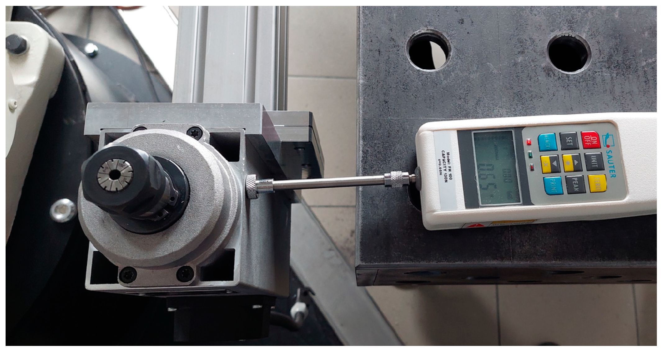
Additionally, to account for potential variations during the grinding process, a compensator featuring a deflection angle φ was designed. This compensator is equipped with two placed springs that serve a dual purpose: they maintain a consistent force 5 N (
Figure 3), which is essential for holding the blade securely without causing damage, and they compensate for tool wear over time. This design ensures that the grinding system remains reliable and accurate even as the tools undergo wear and tear, thereby prolonging the lifespan of the equipment and reducing maintenance needs. By integrating these advanced technologies, the process of grinding turbine blade profiles becomes not only more precise, but also more efficient, enabling industries to maintain high standards of quality and performance in their turbine machines.
The system described relies on advanced communication protocols and integrated measurement systems to achieve this. Specifically, the communication between the KEYENCE controllers and ABB’s PLC and robot controller (
Figure 4) is facilitated by the Profinet protocol, a widely used industrial network protocol that ensures real-time data exchange and high-speed communication between various devices in a manufacturing setup. The Profinet protocol is known for its robustness and reliability, making it an ideal choice for applications where precise control and data accuracy are paramount.
In the setup depicted in
Figure 4, the programmable logic controller (PLC) functions as the central management system, orchestrating the flow of information between different measurement systems and the robotic controller. This PLC is not just a simple controller; it is a sophisticated system that processes inputs from multiple sources and makes real-time decisions to ensure that the manufacturing process is carried out correctly.
The first measurement system involves a KEYENCE XG-X2800 controller working in tandem with a KEYENCE LJ-V7200 laser profilometer. This system’s primary role is to correct the robot’s repeat position when it holds the blade during the measurement process. This correction is critical because even minor deviations in the robot’s positioning can lead to significant errors in the manufacturing process, especially when working with components that require high precision, such as aircraft engine blades.
The second measurement system comprises a KEYENCE LJ-X8000 controller and two KEYENCE LJ-X8080 laser profilometers. This system is tasked with measuring the allowances on both the convex and concave sides of the blade profile at specific sections. The term “allowances” here refers to the material that is intended to be removed during the machining process. Accurate measurement of these allowances is essential to ensure that the blade is machined to the exact specifications required for optimal performance.
3. Results
The measuring system used in this setup is highly sophisticated, utilizing advanced KEYENCE laser profilometers and controllers to achieve the desired precision. After conducting numerous measurement tests, the most effective configuration was determined, which is to set the profilometer heads opposite each other, and the measurement zone is located between them. This strategic placement allows the system to simultaneously measure both the convex and concave sides of the blade, as well as the blade’s thickness at designated sections. This dual measurement capability is crucial for ensuring that the blade maintains its structural integrity and meets all specified dimensions throughout the machining process.
3.1. Measuring System
The blade is delivered into the measurement zone by an ABB IRB 2400 robot, which follows a set of preprogrammed sequences to ensure consistent and accurate placement. This robot is an essential part of the system, as it automates the process of moving the blade into position, reducing the potential for human error and increasing the overall efficiency of the operation.
To create the measurement program, a reference blade with nominal parameters was used. This reference blade serves as the standard against which all subsequent blades are measured. The profiles of this reference blade, held by the ABB robot in sections A-A, B-B, C-C, and D-D (
Figure 5), were stored in the controller’s memory. These stored profiles act as a benchmark, allowing the system to detect even the smallest deviations in the blades being measured and to make the necessary adjustments to ensure that each blade conforms to the required specifications (
Figure 6).
The measurement concept (
Figure 5 and
Figure 6) is central to the operation of the entire system. It illustrates how the blade is positioned within the measurement zone and how the profilometers capture data on both the convex and concave sides, as well as the thickness of the blade. This data are then compared to the stored profiles of the reference blade, enabling the system to calculate the deviations or allowances at each controlled location.
The importance of this measurement process cannot be overstated, as the tolerances involved are extremely tight. Depending on the measurement point, the required tolerance for the blade thickness is approximately ±0.1 mm. This means that the blade must be machined to within one tenth of a millimeter of the specified dimensions, a level of precision that is critical for components used in high-performance applications, such as aircraft engines.
The iterative grinding process aims to bring the blade as close as possible to the dimensions of the reference blade. However, a significant challenge in achieving this is the repeatability of the robot, which is approximately ±0.05 mm. This level of repeatability, while impressive, means that the robot can reintroduce the blade into the measurement zone with a slight variation each time. To address this, the KEYENCE XG-X2800 controller, in conjunction with the KEYENCE LJ-V7200 laser profiler, is used to correct the robot’s repeatability. This correction ensures that the blade is placed in exactly the same position during each measurement cycle, thereby reducing the potential for errors and improving the overall accuracy of the process. Without this correction, deviations would occur, such as excess material on the concave side and insufficient material on the convex side of the blade, or vice versa.
3.2. Selection of Process Parameters
Selecting the optimal process parameters is a critical step in the blade machining process. To achieve this, a solution based on fuzzy logic systems was proposed. Fuzzy logic is a form of multi-valued logic derived from fuzzy set theory to deal with reasoning that is approximate rather than fixed and exact. In this context, it allows for more flexible and adaptive decision making in the machining process, where the exact conditions can vary slightly from one instance to another.
The proposed solution was simulated using Matlab ‘Fuzzy Logic Toolbox’ (
Figure 7). The simulation involved a Mamdani-type fuzzy model, a fuzzy implication of type (MIN), and a sharpening method of type (CA). This model uses fuzzy inference to determine the relationship between the tool’s feed rate and the amount of material removed (referred to as the allowance). The fuzzy rule system was generated based on expert experience.
To accurately determine the allowance value, measurements were taken at twenty evenly spaced points across the surface. Six different feed rates, ranging from 3 to 18 mm/s, were employed in the process of constructing the fuzzy model. This fuzzy model is designed with three input variables denoted as x, y, and N and one output variable, which is the blade feed speed. The coordinates x and y represent the locations of the measurement points on the blade’s surface. Each input variable was partitioned into a specific number of fuzzy sets, ensuring a uniform division of the consideration space. These fuzzy sets were represented using triangular membership functions.
Specifically, the consideration space for the input signal x was divided into five distinct fuzzy sets, labeled from A1 to A5 (
Figure 8). These fuzzy sets represent different regions of the blade along one axis, allowing the system to categorize the position of measurement points on the blade.
The y signal corresponds to the segmentation of the blade into four distinct parts. These four fuzzy sets are labeled B1 to B4 (
Figure 9), and they help break down the blade into different sections for more accurate grinding. This allows the system to handle positional data in along the second axis, ensuring that each section of the blade is treated based on its specific geometry and grinding needs.
The N signal represents the collected allowance, which is the amount of material removed by the tool during the grinding process. The space for N is divided into six fuzzy sets ranging from 0 to 0.18 mm, labeled n1 to n6 (
Figure 10). n1 might represent minimal material removal (close to 0 mm), and n6 could represent the maximum amount of material removed (up to 0.18 mm). This division helps the system understand the current state of material removal, enabling it to adjust the grinding parameters accordingly.
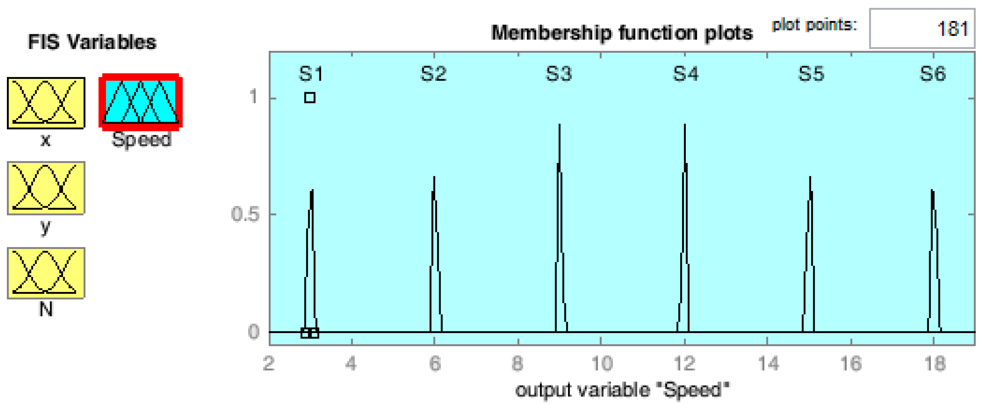
The output signal, which represents the blade feed speed is divided into six triangular fuzzy sets with central values at 3, 6, 9, 12, 15, and 18 mm/s (
Figure 11). Each fuzzy set defines a range of speeds for the grinding tool, with a tolerance of 0.5 mm/s to allow for slight variations in the actual tool speed.
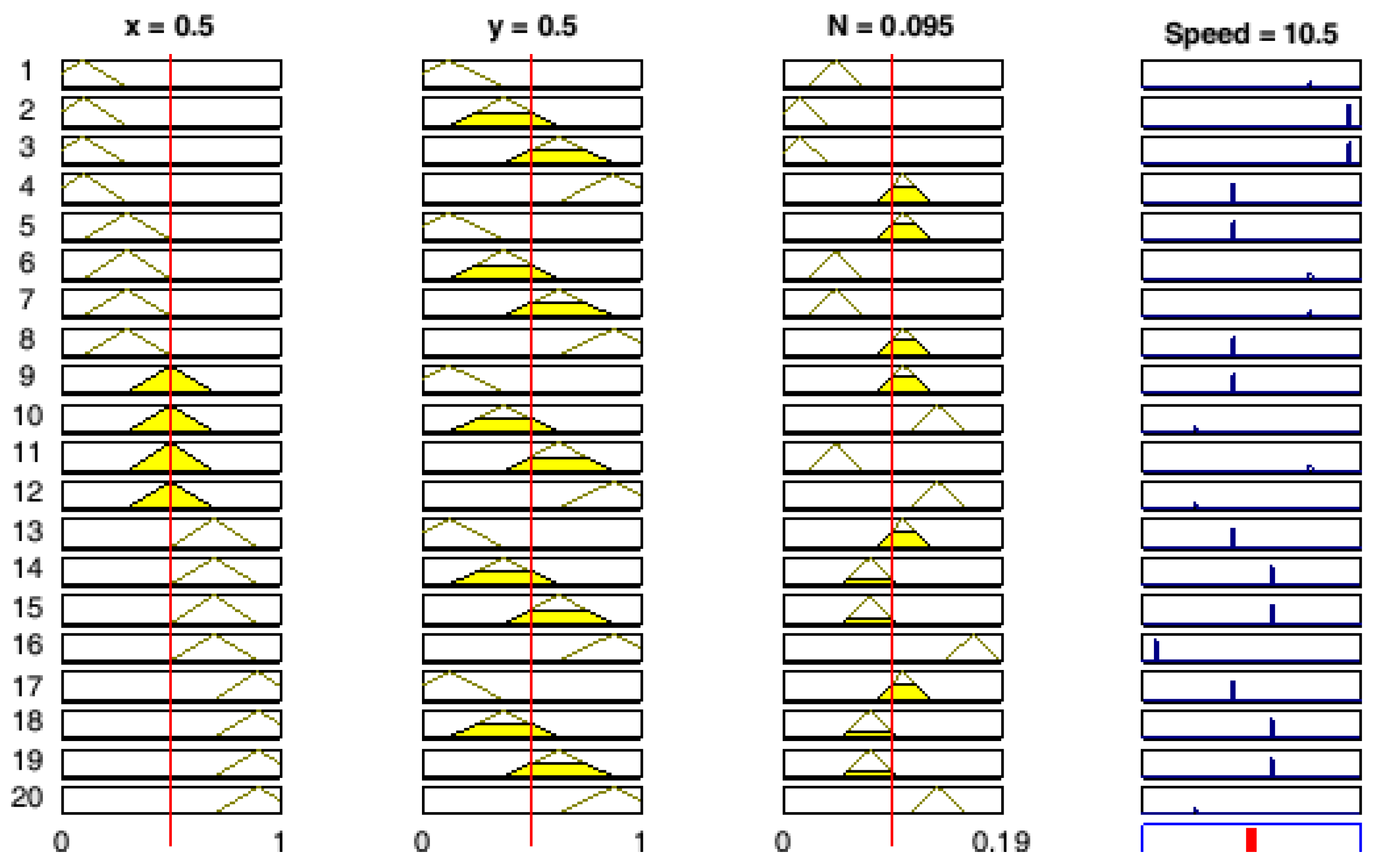
The graphical interpretation of the fuzzy rules is depicted in
Figure 12. Initially, precise values are inputted into the system, which then undergo a process of fuzzification, where these sharp values are transformed into fuzzy sets. This process involves calculating the degree of membership for each fuzzy set, denoted as Ai, Bj, and Nk.
Once fuzzification is complete, the next phase is fuzzy inference, where the system evaluates the degree to which each fuzzy rule is satisfied. In this context, the higher the degree to which a rule’s premise is fulfilled, the greater the membership value assigned to that rule.
In the fuzzy model described, each premise is composed of three simple premises connected by a logical conjunction, specifically the AND operator. This means that for a rule to be considered valid, all three conditions must be met simultaneously. After determining the degree of membership for each rule, the model performs inference. During this stage, the input membership degrees are used to compute the resulting membership function for the model’s output. This step generates the final output based on the aggregation of all the rule evaluations:
The rule base of the fuzzy model is defined by a set of rules, each of which provides a specific action or outcome based on the input conditions. For example, one rule might state: “If the measuring point is defined by the set A1 and B1, and the amount of collected allowance is
n2, then the blade feed speed should be 15 mm/s”. The rule base continues with similar rules, each describing different conditions and corresponding actions to guide the system’s output effectively:
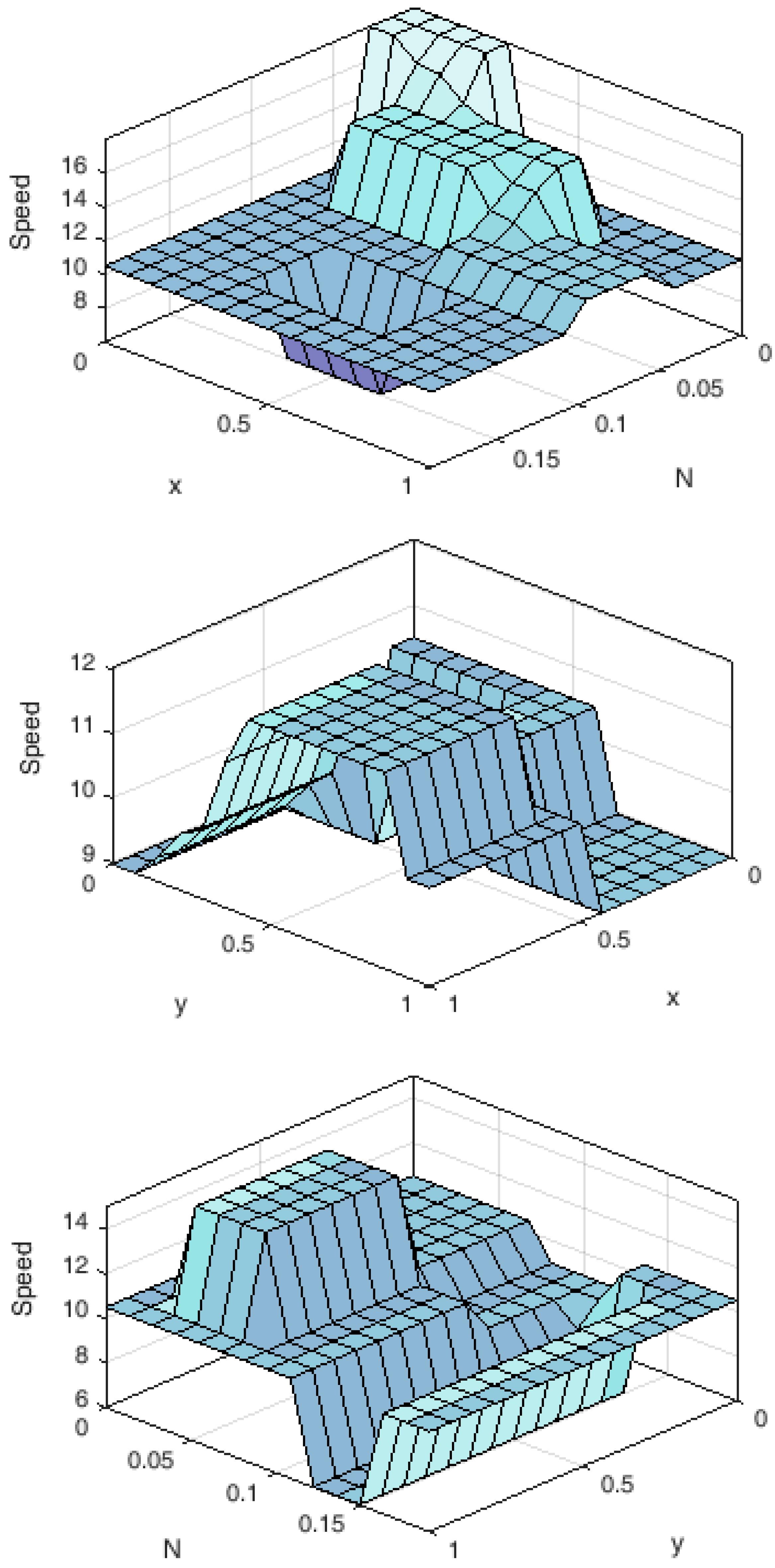
A surface representation of the fuzzy model was also generated (
Figure 13).
An intelligent controller utilizing fuzzy logic was designed to dynamically adjust the tool speed according to the detected material allowance. This method ensures that the blade grinding process remains within specified tolerances by continuously adapting to changes in material conditions. The implementation of this fuzzy logic-based control approach was achieved through the use of PLC Coder. By integrating fuzzy logic, the system enhances precision and reliability in the grinding process, leading to improved quality and performance of the blades.
4. Discussion
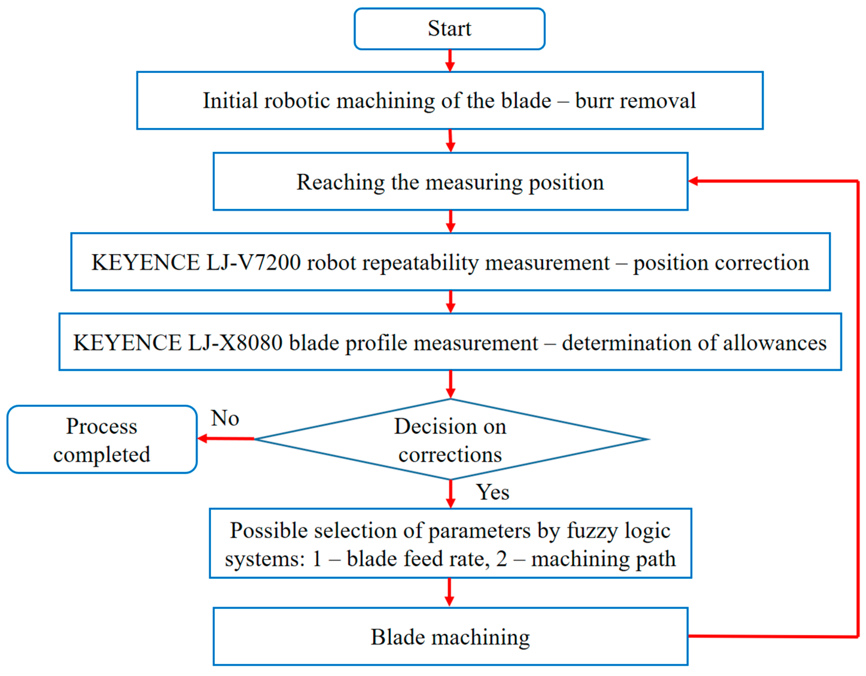
The iterative process algorithm for measuring and grinding an aircraft engine blade using a robotic system is outlined in
Figure 14. This algorithm describes each step in the process, from the initial blade measurement to the final verification of the blade’s conformity to exact specifications.
The process begins with the robot retrieving an aircraft engine blade from a parts magazine using a specially designed gripper. The design of this gripper is crucial, as it must securely hold the blade without damaging it. The blade has sharp edges from previous processes, so the blade is pre-treated with robotic deburring brushes. This pre-treatment is essential, as it removes any unwanted burrs or sharp edges, ensuring the blade is ready for accurate measurement and subsequent machining. Once the pre-treatment is completed, the robot carefully positions the blade at the measurement station. At this point, the blade is aligned with a reference blade profile stored within the system’s program. The alignment is crucial for ensuring that the blade is measured accurately in relation to the predetermined cross sections. Using precision sensors, the system measures the blade at multiple cross sections to determine the allowances—areas where the blade’s geometry deviates from the reference profile. These deviations are critical in identifying the regions where material needs to be removed or adjusted during the machining process. After the allowances are measured and analyzed, the system compares the actual measurements with the reference standards. If the blade already meets the required dimensions, the process is considered complete, and the blade moves to the final stage of verification. However, if deviations are detected, the system initiates corrective actions. In such cases, the system uses a fuzzy logic model to determine the appropriate process parameters for the grinding phase. The fuzzy logic model plays a pivotal role in determining the optimal blade feed speed, and the path the blade should follow during the machining process. This decision-making process ensures that the blade is ground precisely, removing the right amount of material from the necessary areas. Examples of different processing paths that the fuzzy logic system might select are illustrated in
Figure 15. These paths are designed to optimize the grinding process by minimizing material removal while achieving the desired blade shape. The system takes into account factors such as blade geometry, material properties, and the degree of deviation from the reference profile to select the most efficient path for machining.
Following the grinding process, the blade is remeasured to check for conformity. If the blade still does not meet the required tolerances, the system makes further adjustments and repeats the machining and measurement process. This iterative approach continues until the blade’s dimensions match the reference profile within the specified tolerances.
In order to make the proposed solution credible, the results of the blade before and after the machining process were presented. These results were obtained using the Atos Core 135 optical scanner. The proposed algorithm carried out three iterative processes of measurements and grinding and the result is presented in
Figure 16.
The iterative process, although time consuming, ensures a high level of precision and accuracy, which is vital in the aerospace industry where even minor deviations in blade geometry can have significant performance and safety implications. Through this iterative cycle of measurement, grinding, and remeasurement, each blade is machined to the highest standard of precision, ensuring it meets the stringent quality and dimensional requirements of the aerospace sector.
5. Conclusions
The study’s primary goal is to develop a robotic grinding process that adapts to the unique geometric parameters of each blade. This is achieved through the use of iterative measurements and precise control of the robot’s grinding movements, all while ensuring that the blade meets the desired reference profile.
Two laser-based measurement systems are employed to assess the blade’s geometry during the grinding process. These laser heads take precise measurements of the blade’s surface at various stages, allowing the system to continuously monitor the blade’s evolving shape. The iterative nature of the process means that after each round of grinding, the blade is remeasured to compare the current geometry against the reference profile. This allows for real-time adjustments to the grinding process, ensuring high accuracy. The robot’s repeatable ability to return to the same position with precision was adjusted relative to the primary measurement system. This ensures that the robot can perform consistent and accurate grinding operations based on the laser measurements, minimizing deviations that could lead to errors in the final blade shape. Adjusting the robot’s repeatability relative to the primary measurement system is critical because any misalignment between the robot’s movements and the measured blade position could result in over or under grinding, compromising the blade’s performance.
The blade is divided into predefined sections for measurement and grinding. This segmentation allows the system to handle each part of the blade individually, accounting for variations in geometry across different areas. By analyzing the blade in distinct sections, the robot can finetune the grinding process for each area, ensuring that the entire blade is shaped accurately to meet the reference profile. Allowances represent the difference between the current blade geometry and the reference profile, or the target shape that the blade should match. These allowances are measured in relation to the reference profile and provide the data needed to adjust the grinding process. The robotic system uses these allowances to determine how much material needs to be removed from specific sections of the blade. This process is essential for achieving the desired blade shape.
The fuzzy logic system plays a central role in controlling the grinding process by determining the feed rate, or the speed at which the grinding tool moves across the blade. The fuzzy model includes three input signals: x and y, representing the coordinates of measurement points on the blade’s surface, and N, representing the collected allowance (the amount of material to be removed). The output signal is the blade feed speed, which is adjusted based on the input signals. The fuzzy logic system uses triangular membership functions to handle the inherent uncertainties in the measurement and grinding processes, ensuring smooth transitions between different grinding speeds and maintaining precision throughout the operation.
The grinding process is iterative, meaning that it continues in cycles until the desired blade geometry is achieved. After each grinding pass, the blade is remeasured, and the system adjusts the blade feed speed and grinding parameters based on the updated measurements. This cycle of measurement and adjustment continues until the blade’s geometry matches the reference model, ensuring high precision and a final shape that meets the required specifications.
The study successfully designs a robotic grinding process that adapts to each blade’s unique geometry using iterative laser measurements. The fuzzy logic system is key in controlling the blade feed speed based on measurements, which guarantees the precision and efficiency of the grinding process. By continuously refining the process until the blade matches the reference profile, this approach ensures high accuracy, making it ideal for applications where blade geometry is critical.
Work is underway to apply this approach to the lower blade area (
Figure 16—gray). It requires profiled tools or pre-machining with hard tools, which is not so easy due to the profile, limited space, and variable radius.


