Article

An Efficient Reduction of Timer Interrupts for Model Checking of Embedded Assembly Programs

Department of Information Science, Kakuma-Campus, Kanazawa University, Kanazawa 920-1192, Japan
*
Authors to whom correspondence should be addressed.
These authors contributed equally to this work.
Electronics 2024, 13(2), 463; https://doi.org/10.3390/electronics13020463
Submission received: 4 October 2023 / Revised: 14 November 2023 / Accepted: 7 December 2023 / Published: 22 January 2024

Abstract

:
In verifying programs for embedded systems, it is essential to reduce the verification time because state explosion may occur during model checking. One solution is to reduce the number of interrupt handler executions. In particular, when periodic interrupts such as timer interrupts are incorporated, it is necessary to know the physical time. In this paper, we define a control flow automaton (CFA) that can handle time and propose an algorithm based on interrupt handler execution reduction (IHER). The proposed method reduces the number of interrupt executions, including timer interrupts. A case study verified the effectiveness of this algorithm.

1. Introduction

Embedded software is widely used in cell phones, TVs, and cars, and the complexity of both hardware and software has increased over time. Many tests are required for embedded systems because they are subject to many errors. For example, in the automotive industry, safety-critical automotive software requires high reliability, resiliency, and recovery. This affects its design, development, testing, and maintenance. In addition, the number of verifications required increases the time and cost consumption. Not only testing but also strict rules are needed. Formal methods are effective for this purpose. In this paper, we focus on model checking [1]. The model checker in the existing C language is hardware-independent, so it is intended for ANSI-C verification [2]. To verify an embedded system, it is necessary to construct a verification system that takes into account many hardware-dependent functions. In a program written in C, for some types of interrupt service routines (ISRs) the timing of the execution is unpredictable or hard to predict. This causes problems with the verification of the time constraints that embedded and safety-critical software usually feature. Since each state in which an instruction is executed represents a state of each block of the control flow graph (CFG) or CFA, the state explosion problem occurs. B. Schlich et al. developed an interrupt handling execution reduction (IHER) [3] algorithm to suppress the generation of these interrupts. IHER is an algorithm that prevents the interrupt handler (IH) from processing interrupts that occur at specific locations in the program. The core idea is to reduce the number of executions with no dependencies [3]. We will explain the concept of a ’dependency’ in Section 3. If there is a dependency, the execution is allowed to occur, but if there is no dependency, it is not allowed to occur. In B. Schlich’s study, although he used timers in the experiments, there was no mention of periodic timer interrupts. However, timer interrupts are often used in the construction of embedded systems. Therefore, the introduction of the concept of time can contribute to reducing not only simple event interrupts but also periodic interrupts, also called timer interrupts. In this paper, in order to reduce timer interrupts, we define a timed CFA that can handle time, and propose timed IHER.

2. Related Works

In this section, we explain the context of this research in terms of timed models and interrupt processing methods for reducing timer interrupts based on related research.
B. Schlich studied a new method for verifying the assembly code of model checking software for microcontrollers [4]. The simulator based on static analysis constructs a state space, abstracts time, handles non-determinism, and over-approximates the behavior exhibited by the actual microcontroller. On the other hand, our previous paper developed a model checker that uses static and dynamic analysis, such as undefined values [5]. This paper and reference [4] adopt the following different approaches. In the reference, when the model checker requests a successor to a state it has not yet generated, the state space generates the successor on the fly using the simulator. In this paper, the verification system completes the state transition system and passes it to the simulator. This article generates the entire CFG upfront. The latter is better [4], and we will achieve it in the future.
B. Schlich et al. studied IHER to reduce the number of interrupt handler executions [3]. B. Schlich et al. also studied various abstraction techniques based on static program analysis [6]. In this paper, we extend this IHER.
S. Yamane and et al. conducted a study using IHER to enable verification via SMT solvers [7] together with an Assembly Code Block (ACB) [8]. We focus on timer interrupts and do not use SMT solvers for verification.
M. Kuo et al. [9] calculated the worst-case response time (WCRT) using reachability to analyze the assembly code. However, the model was different from that in our study: M. Kuo et al. generated a TCCFG (timed concurrent control flow graph) by static analysis from each assembly code, whereas we verify microcontrollers that run on a single thread and perform model checking.
W. Yajun [10] defined a timed Kripke structure and verified its real-time nature. A timed Kripke structure is a non-deterministic finite automaton but it is not appropriate for our study because its model does not hold the instruction element of the program. We have to control a model by the value of the program counter, and the edges should hold the instruction.
R. Alur and D. L. Dill studied timed automata [11]. A timed automaton, an extension of a finite-state automaton, is a model that describes a system by both discrete events and a continuous time lapse according to state transitions. On the other hand, in this study, we develop a timed CFA for the execution time of an assembly program. The object of our study is different from timed automata. The proposed structure deals with discrete time, and we use the execution time of each instruction of the assembly program in each state.
Our previous study [12] reduced timer interrupts to include real-time performance. This study differs in that it does not consider real-time performance but defines the algorithm more concretely and conducts experiments using multiple timer interrupts in a case study.
Recently, L. Lihao et al. proposed an efficient verification of low-level embedded C software with interrupts based on partial-order coding and symbolic execution [13]. On the other hand, this paper verifies an assembly program with an algorithm that also reduces timer interrupts based on the reducing the number of interrupt handlers by IHER; if the method of L. Liang et al. is adopted, nested interrupts can be handled effectively in this paper.

3. IHER

IHER is a method developed by B.Schlich et al. to block the execution of IHs as much as possible. It is an abstraction technique based on partial order reduction [14]. If there is no dependency between the IH and the main program, the IH’s execution is reduced by blocking the IH. The core idea of dependency is that one instruction influences another.
For example, when an assembly instruction of the IH and the main program read/write in the same memory location, the overall processing behavior of the program may change according to whether the interrupt is blocked or not. This technique was developed to execute the IH only when there are such behavior changes. IHER consists of the following four steps:
  • Detect dependencies between IHs.
    Step 1 is performed when two or more IHs exist. i , j IH depend on each other if any of the following conditions are true (access here means both writing and reading):
    • One IH enables or disables the other IH;
    • One IH writes to a memory location accessed by the other IH;
    • One IH writes to the memory location used in an atomic proposition (AP).
    Examples of APs include a variable being equal to a certain value. An IH that manipulates the memory location of an AP manipulates the core of the program. It is therefore necessarily associated with all IHs. In other words, only one IH is mentioned, and if one IH writes the memory location used by the AP, then all IHs are dependent on each other.
  • Detect dependencies between program locations and IHs.
    Step 2 shows the conditions under which two labels, the e x e c u t i o n i label and the b a r r i e r i label, are attached to locations to detect dependencies between the program and the IH. An e x e c u t i o n i label allows the execution of an IH after the execution of the program instruction. On the other hand, the label b a r r i e r i denotes that there exists a dependency between that program location and an IH, and therefore this IH needs to be executed before the instruction at that location is executed. In determining the label, we assume that program location k is a direct predecessor of program location l. Let program location k be a direct predecessor of program location l. Formally, for each i I H , l is labeled with e x e c u t i o n i if one of the following conditions is satisfied:
    • k enables or disables i;
    • k writes a memory location that i accessed;
    • k writes a memory location that is used in an AP.
    Also, for each i IH, a program location l is labeled with b a r r i e r i if one of the following conditions is satisfied.
    • i writes a memory location that l accesses;
    • l enables or disables i;
    • l writes a memory location that i accesses;
    • l writes a memory location that is used in an AP.
  • Refine results.
    Step 3 performs refinement on the e x e c u t i o n i label. Each e x e c u t i o n i label is moved until one of the following conditions is satisfied.
    • A program location labeled with b a r r i e r i is reached;
    • A loop entry is found;
    • A loop exit is found.
  • Label blocking locations.
    In the last step, all program node positions are labeled IH. At this point, i IH, and we assign a b l o c k i n g i label to any location without an e x e c u t i o n i label.
IHER can reduce the number of program locations where an interrupt handler (IH) may execute. In this paper, we use IHER to reduce the state space. The paper by B. Schlich proved that the model checking of CTL*-X is valid even though IHER reduces the number of program locations where the execution of an interrupt handler (IH) must be considered. Here, CTL*-X is defined as prohibiting the next time operator X in the CTL* formulas [15]. In this paper, since safety is verified for the assembly code using a subclass of CTL*-X, the verification is valid even if the IHER reduces the location of the assembly program.

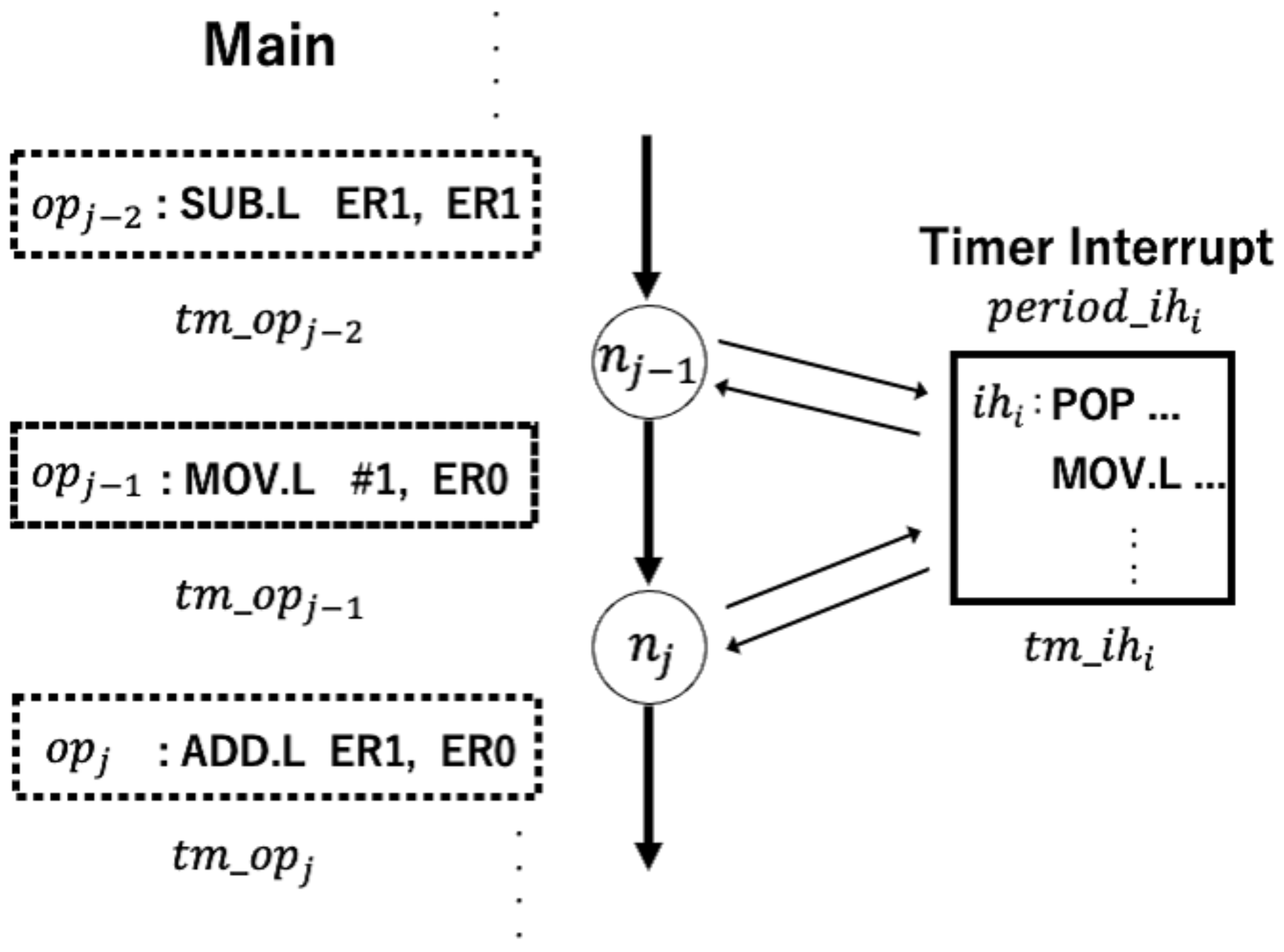
4. Formal Model of an Assembly Program

In this paper, the assembly program is applied to a CFA (control flow automaton) [16] because an IH can occur at every assembly instruction. In Shlich’s study [3], IHER was explained using a CFG [17,18], which is different from a CFA. Nodes in a CFA are program locations, and directed edges between nodes are instructions that are executed when a control moves from the source to the destination. In this paper, since time must be calculated when dealing with timer interrupts in the static analysis, we use the execution time of instructions to calculate the time. Therefore, we define a timed CFA, which extends the CFA and introduces the concept of time. While Toth et al.’s TCFA represented real number time, our timed CFA represents natural number time to handle program execution time [19]. We deal with exact program execution times, while Ermedahl et al. dealt with worst-case and best-case response times [20]. The paper by G. Hou et al. treated interrupts as randomly occurring [21]. Our paper covers all possible interruptions.
The timed CFA of the assembly program is defined as N = ( L , l 0 , O , I , , T ) , where:
-
L is a set of program locations;
-
l 0 L, and l 0 is the initial location of the program;
-
O is a finite set of instructions in the main program (non-interrupt);
-
I is a finite set of executions of interrupt handlers;
-
T indicates execution times such as the OT and IT of each instruction in O and I at each program location;
-
→⊆ L × O × O T × I × I T × L is the set of transition relations.
The “execution time of each instruction in O and I” refers to a single natural number. Also, it is a point in time after program execution begins. There is an O and I within the same transition, with both O and I executed in the transition.
We consider only the fact that the execution time of the interrupt handler has to be constant. We represent branching based on data from the timed CFA with branched structures.
In addition, each node is shown as follows: n j , where n j = ( l j , o p j , t m _ o p j , i h i , t m _ i h i , l j + 1 ) . The assumption is that i is the number of interrupts and j is the number of nodes. l j is the current location of the timed CFA, o p j is the instruction of the program, t m _ o p j is the execution time of the instruction in the program, i h i is the interrupt handler, t m _ i h i is the execution time of the interrupt handler executions, and l j + 1 is the next location of the timed CFA.
An example of the timed CFA is shown in Figure 1. The right side of the figure represents a timer interrupt, and p e r i o d _ i h i represents the timer period. The time can be accurately calculated by having each node hold the execution time of the instruction. Instructions are microcontroller instructions, such as SUB.L and MOV.L, and are associated with transitions.

5. Proposed Method of Timed IHER

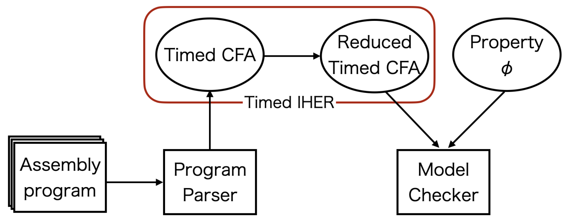
5.1. Verification System

This subsection describes the verification system used in this paper (Figure 2). As a premise, this study used the assembly code corresponding to the H8/3687F microcontroller [22] manufactured by Electronics Corporation (Tokyo, Japan) as the verification target and conducted implementation and experiments. The details are explained in the experimental section. First, the assembly code was subjected to lexical analysis and syntax analysis by a lexer and parser, respectively. We used JFlex v1.9.1 (created by Scott Hudson affiliated with CMU in USA) [23] and BYACC/J v1.15 (created by Florian Weimer affiliated with University Stuttgart in Deutschland) [24] in Java v17 to develop the lexer and parser. Next, the timed CFA was constructed from the memory map and the parsed code. Then, a static analysis called timed IHER, the proposed method, was performed to output a timed CFA with reduced interrupt executable locations. The timed CFA was then input into the model checker along with the verification properties to confirm that the state space could be reduced.

5.2. Algorithm

The timed IHER algorithm is described in Algorithm 1. The central idea is to suppress execution at the node of occurrence by strictly calculating the execution time not only for interrupts due to events but also for timer interrupts.
In step 1, the dependencies between interrupts are detected. This is achieved under the same conditions as in existing research [3]. If the timer interrupt is ready to be executed, it must be executed in the same way as the dependent interrupt.
Algorithm 1 Timed IHER
Require: Timed CFA
Ensure: Reduced Timed CFA
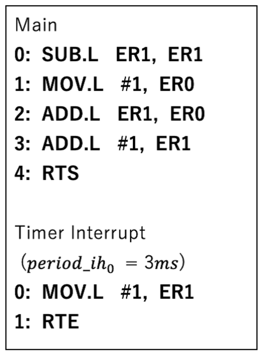
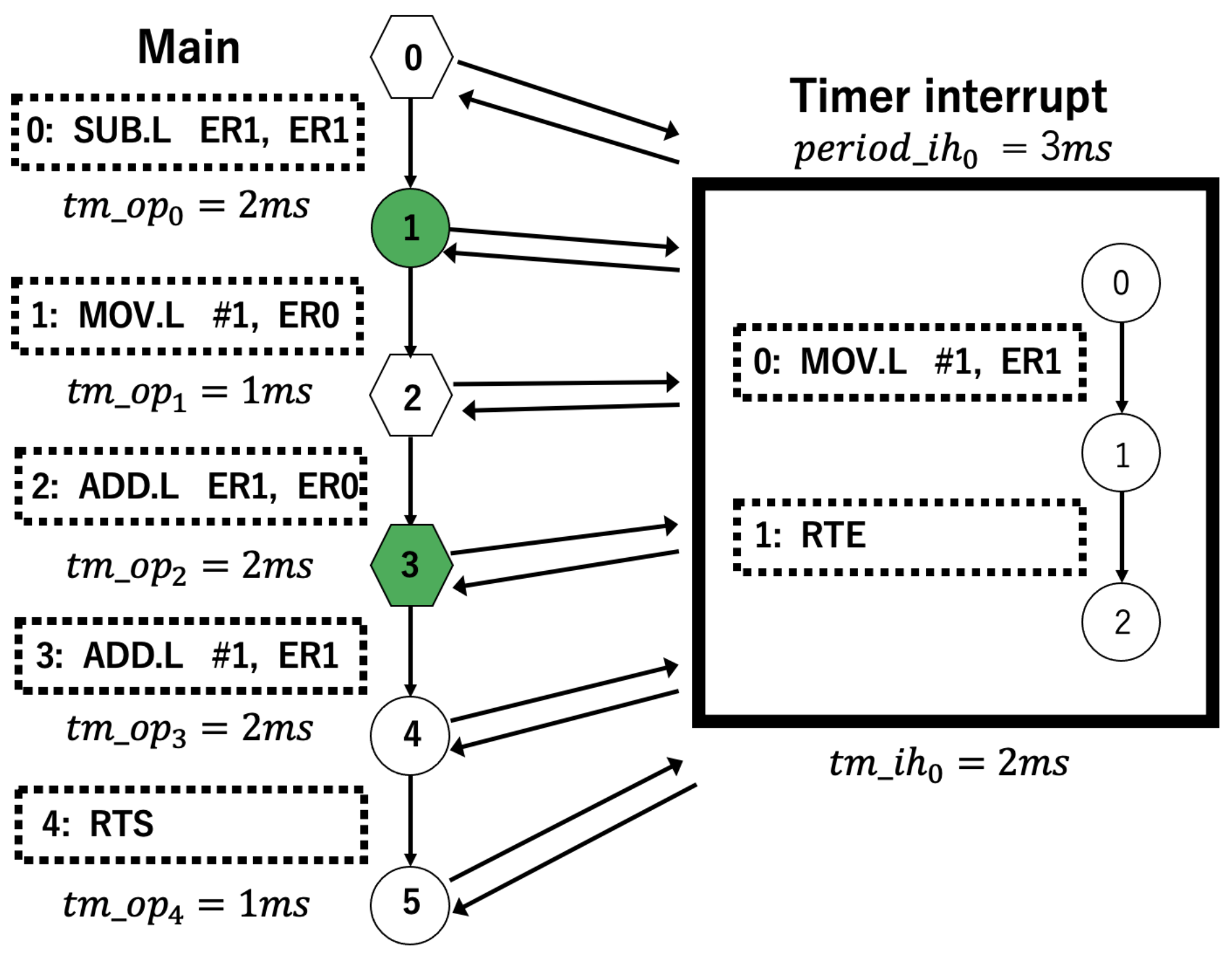
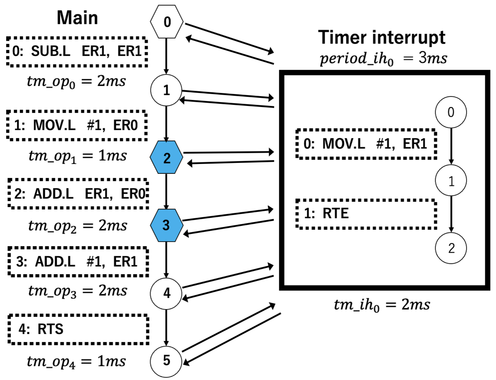
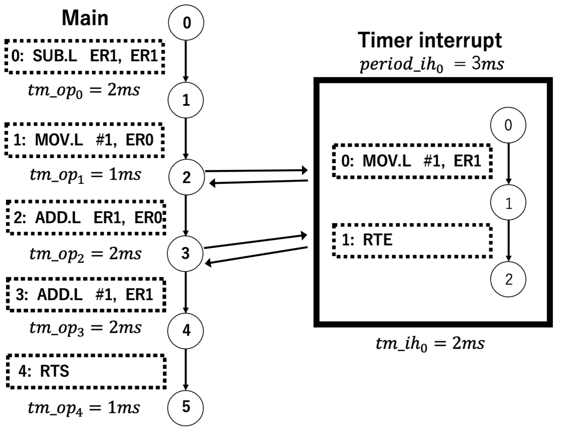
  1:
n j = ( l j , o p j , t m _ o p j , i h i , t m _ i h i , l j + 1 )
  2:
ε ( n j ) // the conditions for e x e c u t i o n i in step 2 of IHER
  3:
ψ ( n j ) // the conditions for b a r r i e r i in step 2 of IHER
  4:
p e r i o d _ i h i // the timer period of each timer interrupt
  5:
L ( n j ) // sets of labels at the node
  6:
p r e _ t i m e [ j ] [ i ] // the timer value at p r e _ t i m e r _ e x e c u t i o n i
  7:
T M i // the total instruction execution time
  8:
x // the node number after transition in step 3
  9:
// step 1
10:
Detect dependencies between i h i
11:
// step 2
12:
for  o p j of n j  do
13:
for  i h i interrupts do
14:
  if  i h i is timer interrupts then
15:
   if  p e r i o d _ i h i T M i && ε ( n j 1 ) == true then
16:
     L ( n j ) := L ( n j ) t i m e r _ e x e c u t i o n i
17:
     i . T M i += t m _ i h i
18:
     T M i %= p e r i o d _ i h i
19:
   else if  p e r i o d _ i h i > T M i && ε ( n j 1 ) == true then
20:
     L ( n j ) := L ( n j ) p r e _ t i m e r _ e x e c u t i o n i
21:
     p r e _ t i m e [ j ] [ i ] = T M i
22:
     T M i -= p e r i o d _ i h i
23:
   end if
24:
   if  ψ ( n j ) == true then
25:
     L ( n j ) := L ( n j ) t i m e r _ b a r r i e r i
26:
   end if
27:
  else
28:
   if  ε ( n j 1 ) == true then
29:
     L ( n j ) := L ( n j ) e x e c u t i o n i
30:
     i . T M i += t m _ i h i
31:
   end if
32:
   if  ψ ( n j ) == true then
33:
     L ( n j ) := L ( n j ) b a r r i e r i
34:
   end if
35:
  end if
36:
end for
37:
i . T M i += t m _ o p j
38:
end for
39:
// step 3
40:
for  o p j of n j  do
41:
for  i h i interrupts do
42:
  if  t i m e r _ e x e c u t i o n i L ( n j ) then
43:
   Transition to a node with a t i m e r _ b a r r i e r i
   loop entry or loop exit
44:
    L ( n x ) := L ( n x ) t i m e r _ e x e c u t i o n i
45:
  else if  p r e _ t i m e r _ e x e c u t i o n i L ( n j ) then
46:
   Transition to a node with a t i m e r _ b a r r i e r i
   loop entry or loop exit
47:
    p r e _ t i m e [ j ] [ i ] += total time of passed nodes
48:
   if  p e r i o d _ i h i p r e _ t i m e [ j ] [ i ]  then
49:
     L ( n x ) := L ( n x ) t i m e r _ e x e c u t i o n i
50:
    for all j such that x j  do
51:
      i . p r e _ t i m e [ j ] [ i ] += t m _ i h i
52:
    end for
53:
   else
54:
     L ( n x ) := L ( n x ) b l o c k i n g i
55:
   end if
56:
  end if
57:
  if  e x e c u t i o n i L ( n j )  then
58:
   Transition to a node with a b a r r i e r i
   loop entry or loop exit
59:
    L ( n x ) := L ( n x ) e x e c u t i o n i
60:
  end if
61:
end for
62:
 //step 4
63:
for  n j  do
64:
  if ( t i m e r _ e x e c u t i o n i || e x e c u t i o n i ) L ( n j )  then
65:
    L ( n j ) := L ( n j ) b l o c k i n g i
66:
  end if
67:
end for
68:
end for
In step 2, the execution time is calculated and the label is determined. For this purpose, the labels are determined for each interrupt in order of execution priority, and the cases are divided into timer interrupts and other interrupts. In the latter case, the conventional e x e c u t i o n i and b a r r i e r i labels are used. In the former case, it is first determined whether the total instruction execution time T M i exceeds p e r i o d _ i h i , which is the timer period. Then, if the same conditions as for the e x e c u t i o n i label are satisfied, the t i m e r _ e x e c u t i o n i label is applied to the node, the execution time of the interrupt process is added to all T M i , and T M i is assigned through division by p e r i o d _ i h i . If T M i does not exceed p e r i o d _ i h i , the current timer time is stored in p r e _ t i m e [ j ] [ i ] for use in step 3, T M i is assigned by subtracting p e r i o d _ i h i , and the label p r e _ t i m e r _ e x e c u t i o n i is applied. Also, if the same conditions for the b a r r i e r i label are satisfied, then the node should be labeled t i m e r _ b a r r i e r i . Finally, the instruction time of the main program of the current node is added, and the next node is checked.
In step 3, refinements are made to the t i m e r _ e x e c u t i o n i and e x e c u t i o n i labels. The t i m e r _ e x e c u t i o n i label is moved until reaching the t i m e r _ b a r r i e r i label, i.e., the entrance or exit of the loop. The e x e c u t i o n i label is moved until reaching the b a r r i e r i label, i.e., the entrance or exit of the loop. If one of the following is satisfied, we label the node with t i m e r _ e x e c u t i o n i or e x e c u t i o n i , and x is the node number after the transition. On the other hand, in the case of the p r e _ t i m e r _ e x e c u t i o n i label, we add the execution time of the instruction of the node that has passed to p r e _ t i m e [ j ] [ i ] , including the instruction of the interrupt when it reaches a node satisfying the same conditions as the t i m e r _ e x e c u t i o n i label in the transition. If this p r e _ t i m e [ j ] [ i ] exceeds p e r i o d _ i h i , the label t i m e r _ b a r r i e r i is applied, and we add the execution time of the interrupt to p r e _ t i m e [ j ] [ i ] after the transitioned node destination. In other words, even when the timer period has not elapsed in step 2, if it has elapsed at the destination, the execution of the timer interrupt is permitted. We can accurately calculate the time by adding the execution time to the timer of the p r e _ t i m e r _ e x e c u t i o n i label and the other timer interrupt after the node following the transition, to the extent that we do not add them in step 2.
In step 4, the label b l o c k i n g i is applied to block interrupts at node positions other than those where the labels e x e c u t i o n i or t i m e r _ e x e c u t i o n i are not applied. This is the algorithm of the proposed method.
The reason for the subtraction at line 24 is to distinguish p r e _ t i m e r _ e x e c u t i o n i from the t i m e r _ e x e c u t i o n i label and to prevent execution even though permission to execute has not been granted. For example, if both nodes before and after the p r e _ t i m e r _ e x e c u t i o n i label are converted to the t i m e r _ e x e c u t i o n i label in step 3, and the node is actually executed, the timer at the later node may not overflow.

5.3. Example

For a better understanding of the algorithm, we will present a simple example.
We apply timed IHER to the simple code written in Figure 3. To simplify the time, we include one timer interrupt with a period of 3 ms and set the execution time of each instruction as shown in Figure 4. The p r e _ t i m e r _ e x e c u t i o n 0 label is green, the t i m e r _ e x e c u t i o n 0 label is blue, and the t i m e r _ b a r r i e r 0 label is hexagonal.
First, we perform labeling in step 2. At n 0 , the condition of t i m e r _ b a r r i e r i is satisfied. At n 1 , since T M 0 is 2 ms, it is less than the period, and the condition of p r e _ t i m e r _ e x e c u t i o n i is satisfied. Then, after T M 0 is assigned to p r e _ t i m e [ 1 ] [ 0 ] , p e r i o d _ i h 0 is subtracted from T M 0 . At n 2 , the condition of t i m e r _ b a r r i e r i is satisfied, and T M 0 is 0 ms. At n 3 , T M 0 is 2 ms, so the condition of p r e _ t i m e r _ e x e c u t i o n i is satisfied as with n 1 . Then, after assigning T M 0 to p r e _ t i m e [ 3 ] [ 0 ] , p e r i o d _ i h 0 is subtracted from T M 0 . The condition for t i m e r _ b a r r i e r 0 is also satisfied, so this label is applied. Since n 4 and n 5 do not satisfy any of the conditions, step 2 follows the scheme presented in Figure 4.
Next, we perform refinement in step 3. First, p r e _ t i m e r _ e x e c u t i o n 0 of n 1 is transitioned to n 2 and labeled t i m e r _ b a r r i e r 0 . At this time, the 1 ms of the M O V instruction is added to the 2 ms stored in p r e _ t i m e [ 1 ] [ 0 ] , resulting in 3 ms, which is equal to the 3 ms of the timer period, allowing the execution. Therefore, n 2 is labeled t i m e r _ e x e c u t i o n 0 . The execution time of the timer interrupt must be added to p r e _ t i m e [ j ] [ i ] after n 2 . Thus, since the 2 ms of the timer interrupt is added to the 2 ms stored in p r e _ t i m e [ 3 ] [ 0 ] to obtain 4 ms, and n 3 is labeled t i m e r _ b a r r i e r 0 , the label t i m e r _ e x e c u t i o n 0 is applied. Step 3 is shown in Figure 5.
Finally, in step 4, the execution of the timer interrupt is suppressed by labeling with b l o c k i n g 0 the nodes that are not labeled with t i m e r _ e x e c u t i o n 0 . The result is shown in Figure 6. The b l o c k i n g 0 label is applied to multiple locations (0, 1, 4, and 5) with no interruptions.

5.4. Computational Analysis and Partial Correctness of Algorithm 1

5.4.1. Computational Analysis of Algorithm 1

The computational analysis of our proposed algorithm is presented below:
  • Step 1.
    Let | i h i | be the number of locations in the interrupt handler i h i , i = 1 , , m . The time complexity is O ( | i h 1 | × × | i h m | ) .
  • Step 2:
    j is the number of nodes, and | o p j | is the number of instructions in n j . Also, | I n t e r r u p t s | is the number of interrupts. The time complexity is O ( j × | o p | | × | I n t e r r u p t s | ) .
  • Step 3:
    The time complexity is O ( j × | o p j | × | I n t e r r u p t s | ) .
  • Step 4:
    The time complexity is O ( j × | o p j | ) .
From step 1 to step 4, the total time complexity is O ( | i h 1 | × × | i h m | + j × | o p j | × | I n t e r r u p t s | ) .

5.4.2. Partial Correctness of Algorithm 1

The partial correctness of our proposed algorithm is presented below.
We justify our algorithm in terms of the following two aspects:
  • The correctness of the theory of timed IHER.
    We establish the correctness of our timed IHER by showing that the original timed CFA G and the reduced timed CFA G r e d u c e d are equivalent. According to the reference [3], we can show the correctness of the time interrupt reduction by defining the semantics of a timed CFA using a labeled transition system. Only a summary of the correctness is given below. We define the labeled transition system T ( G ) of a timed CFA G and the labeled transition system T ( G r e d u c e d ) of a reduced timed CFA G r e d u c e d by timed IHER. We can establish the correctness of our timed IHER by showing that the original timed CFA G and the reduced timed CFA G r e d u c e d are equivalent. More concretely, we can show that the original timed CFA G and the reduced timed CFA G r e d u c e d are related by divergence-sensitive stutter bisimulation [15,25].
  • The correctness of the algorithm of timed IHER.
    We show that the reduced timed CFA G r e d u c e d resulting from timed IHER is correctly constructed by our algorithm. The fundamental idea of Schlich’s IHER is to reduce the number of normal IH executions by blocking normal HIs at program locations where there is no dependency between certain normal HIs and the program [3]. Also, the fundamental idea of our proposed timed IHER is to reduce the number of timer IH executions by blocking timer HIs at program locations where there is no dependency between certain timer HIs and the program. In order to realize timed IHER, we deal with the execution time of the program. For reasons of space limitation, this section will focus on the key points such as step 2 and step 3 of the algorithm:
    a
    Step 2.
    The execution time is calculated and the label is determined. First, in order to calculate the execution time, the outermost loop denoted by “FOR o p j of n j ” adds up the execution times of the instructions. Next, the inner loop denoted by “FOR i h i interrupts” depends on whether timer interrupts or normal interrupts are used as follows:
    a-1
    Timer interrupts.
    If the same conditions as for the e x e c u t i o n i label are satisfied, the t i m e r _ e x e c u t i o n i label is applied to the node, the execution time of the interrupt process is added to all T M i , and T M i is assigned through division by p e r i o d _ i h i . If T M i does not exceed p e r i o d _ i h i , the current timer time is stored in p r e _ t i m e [ j ] [ i ] for use in step 3, T M i is assigned by subtracting p e r i o d _ i h i , and the label p r e _ t i m e r _ e x e c u t i o n i is applied. Also, if the same conditions for the b a r r i e r i label are satisfied, then the node should be labeled t i m e r _ b a r r i e r i .
    a-2
    Normal interrupts. We label locations with e x e c u t i o n i and b a r r i e r i according to [3].
    b
    Step 3.
    The outermost loop denoted by “FOR o p j of n j ” refines the t i m e r _ e x e c u t i o n i and e x e c u t i o n i labels. The t i m e r _ e x e c u t i o n i label is moved until reaching the t i m e r _ b a r r i e r i label, i.e., the entrance or exit of the loop. The e x e c u t i o n i label is moved until reaching the b a r r i e r i label, i.e., the entrance or exit of the loop.
    c
    Step 4.
    As locations without e x e c u t i o n i or t i m e r _ e x e c u t i o n i labels do not affect the execution and can be reduced, the label b l o c k i n g i is applied to block interrupts at these locations.

6. Experiment

We developed our own model checker. We performed our validation in the environment shown in Table 1.
In this experiment, the assembly code for the Renesas Electronics H8/3687F microcontroller [22] was used as the verification target, and implementation and experiments were conducted. All general-purpose registers were 16 bits wide, and 16 registers ( E 0 E 7 and R 0 R 7 ) were installed. When general-purpose registers were used as data registers, they could be accessed as 8-, 16-, or 32-bit registers. When 32-bit registers were accessed, E and R were integrated and handled as ER registers, of which ER7 functioned as the stack pointer ( S P ). On the other hand, the control register consisted of one 24-bit-wide program counter register ( P C ) and one 8-bit-wide condition code register ( C C R ). The total address space for the program and data area was 64 Kbytes.
We examined three cases. In each case, we conducted experiments for several combinations of the number of timer interrupts (TIs) and software interrupts (SIs). Case 1 was used for transfer by the serial communication interface (SCI3) with two timer interrupts. Case 2 used two LEDs. Two timer interrupts were used, the first to light one LED at a prime number and the second to light the other LED at an even number, adding 1 every 0.5 s until the number rose from 0 to 10. Case 3 was a PID control program. One timer interrupt acquired the sensor value and set a new target current value when a timer overflow occurred. When the other timer overflowed, the timer interrupt performed PID control for a fixed cycle based on the current target value and the measured current value and output the value to the motor. All three cases were implemented in e-nuvo WHEEL [26], and the verification property was A G ¬ e r r o r . e-nuvo WHEEL is a microcomputer-controlled robot. The reference language was Japanese. Only a manual in Japanese exists.
Table 2 shows the required memory, execution time, and state space reduction rate for cases 1 through 3. The required memory was computed by an activity monitor. We confirmed a reduction of about 90% for case 1 and case 3 and a reduction of about 60% for case 2, but the reduction rate and execution time varied greatly depending on the number of programs and interrupts.

7. Conclusions

In this paper, we proposed a formal model and algorithm based on IHER that can reduce timer interrupts. Twelve thousand lines of Java code were used to develop the entire system, including model building and model checking, and its effectiveness was demonstrated. However, the system does not strictly take into account priority and multiple interrupts and is limited to verification when the program is executed in a certain position. Also, the optimal refinement of timers when loops exist in the program is unknown. Therefore, the handling of loops, including strict timer understanding, must be studied. Currently, we are considering algorithms that can further reduce the number of states and aiming to expand the scope of applications for the proposed method.
Since the current version is a prototype, we will develop a fully fledged system and conduct more experiments in the future.

Author Contributions

Conceptualization, S.Y.; methodology, S.Y. and T.K.; software, T.K. and Y.W.; validation, S.Y., T.K. and Y.W.; formal analysis, T.K. and Y.W.; investigation, S.Y.; resources, S.Y.; data curation, T.K.; writing—original draft preparation, T.K. and Y.W.; writing—review and editing, S.Y.; visualization, S.Y.; supervision, S.Y.; project administration, S.Y.; funding acquisition, S.Y. All authors have agreed to the final version of the manuscript.

Funding

This research was funded by JSPS KAKENHI Grant Number 21K11824.

Data Availability Statement

Data are available upon request from authors.

Conflicts of Interest

The authors declare no conflict of interest.

References

  1. Clarke, E.M.; Grumberg, O.; Peled, D. Model Checking; The MIT Press: Cambridge, MA, USA, 1999. [Google Scholar]
  2. Schlich, B.; Kowalewski, S. Model checking C source code for embedded systems. Int. J. Softw. Tools Technol. Transf. 2009, 11, 187–202. [Google Scholar] [CrossRef]
  3. Schlich, B.; Thomas, N.; Brauer, J.; Brutschy, L. Reduction of interrupt handler executions for model checking embedded software. In Proceedings of the Haifa Verification Conference, Haifa, Israel, 19–22 October 2009; Springer: Berlin/Heidelberg, Germany, 2009; pp. 5–20. [Google Scholar]
  4. Schlich, B. Model Checking of Software for Microcontrollers. ACM Trans. Embed. Comput. Syst. 2010, 9, 1–27. [Google Scholar] [CrossRef]
  5. Yamane, S.; Konoshita, R.; Kato, T. Model checking of embedded assembly program based on simulation. IEICE Trans. Inf. Syst. 2017, 100, 1819–1826. [Google Scholar] [CrossRef]
  6. Schlich, B.; Brauer, J.; Kowalewski, S. Application of static analyses for state-space reduction to the microcontroller binary code. Sci. Comput. Program 2011, 76, 100–118. [Google Scholar] [CrossRef]
  7. Armando, A.; Mantovani, J.; Platania, L. Bounded model checking of software using SMT solvers instead of SAT solvers. Int. J. Softw. Tools Technol. Transf. 2009, 11, 69–83. [Google Scholar] [CrossRef]
  8. Yamane, S.; Kobashi, J.; Uemura, K. Verification Method of Safety Properties of Embedded Assembly Program by Combining SMT-Based Bounded Model Checking and Reduction of Interrupt Handler Executions. Electronics 2020, 9, 1060. [Google Scholar] [CrossRef]
  9. Kuo, M.; Sinha, M.; Roop, P. Efficient WCRT analysis of synchronous programs using reachability. In Proceedings of the 48th Design Automation Conference (DAC ’11), San Diego, CA, USA, 5–10 June 2011; Association for Computing Machinery: New York, NY, USA, 2011; pp. 480–485. [Google Scholar]
  10. Wu, Y.; Yamane, S. Model Checking of Real-Time Properties for Embedded Assembly Program Using Real-Time Temporal Logic RTCTL and Its Application to Real Microcontroller Software. IEICE Trans. Inf. Syst. 2020, 103, 800–812. [Google Scholar] [CrossRef]
  11. Alur, R.; Dill, D. The theory of timed automata. In Proceedings of the Real-Time: Theory in Practice: REX Workshop Mook, 1991 Proceedings, Mook, The Netherlands, 3–7 June 1991; Springer: Berlin/Heidelberg, Germany, 1992. [Google Scholar]
  12. Kiriyama, T.; Wu, Y.; Yamane, S. Reduction of Timer Interrupts for Embedded Assembly Programs Based on Reduction of Interrupt Handler Executions. In Proceedings of the 2021 IEEE 10th Global Conference on Consumer Electronics (GCCE), Kyoto, Japan, 12–15 October 2021; IEEE: Piscataway, NJ, USA, 2021; pp. 464–466. [Google Scholar]
  13. Liang, L.; Melham, T.; Kroening, D.; Schrammel, P. Tautschnig, M. Effective Verification for Low-Level Software with Competing Interrupts. ACM Trans. Embed. Comput. Syst. 2018, 17, 36:1–36:26. [Google Scholar] [CrossRef]
  14. Peled, D. Ten years of partial order reduction. In Proceedings of the CAV 1998, LNCS, Vancouver, BC, Canada, 28 June–2 July 1998; Hu, A.J., Vardi, M.Y., Eds.; Springer: Berlin/Heidelberg, Germany, 1998; Volume 1427, pp. 17–28. [Google Scholar]
  15. Browne, M.C.; Clarke, E.M.; Grumberg, O. Characterizing Finite Kripke Structures in Propositional Temporal Logic. Theor. Comput. Sci. 1988, 59, 115–131. [Google Scholar] [CrossRef]
  16. Beyer, D.; Henzinger, T.A.; Jhala, R.; Majumdar, R. The software model checker blast. Int. J. Softw. Tools Technol. Transf. 2007, 9, 505–525. [Google Scholar] [CrossRef]
  17. Muchnick, S. Advanced Compiler Design and Implementation; Morgan Kaufmann Publishers Inc.: Burlington, MA, USA, 1997. [Google Scholar]
  18. Aho, A.V.; Sethi, R.; Ullman, J.D. Compilers: Principles, Techniques and Tools, 2nd ed.; Pearson: London, UK, 2006. [Google Scholar]
  19. Toth, T.; Majzik, I. Formal Modeling of Real-Time Systems with Data Processing. In Proceedings of the 23rd PhD Mini-Symposium; Pataki, B., Ed.; Budapest University of Technology and Economics: Budapest, Hungary, 2016; pp. 46–49. [Google Scholar]
  20. Ermedahl, A.; Engblom, J. Execution Time Analysis for Embedded Real-Time Systems. In Handbook of Real-Time and Embedded Systems; CRC Press: Boca Raton, FL, USA, 2007. [Google Scholar]
  21. Hou, G.; Kong, W.; Zhou, K.; Wang, J.; Cao, X.; Fukuda, A. Analysis of Interrupt Behavior Based on Probabilistic Model Checking. In Proceedings of the 2018 7th International Congress on Advanced Applied Informatics (IIAI-AAI), Yonago, Japan, 8–13 July 2018; pp. 86–91. [Google Scholar]
  22. Corporation, R.E. Renesas Electronics, Renesas Electronics Corporation (Online). Available online: http://japan.renesas.com/ (accessed on 12 October 2019).
  23. JFlex—The Fast Scanner Generator for Java. 2015. Available online: http://jflex.de/ (accessed on 11 March 2023).
  24. BYACC/J Java Extension. 2013. Available online: http://byaccj.sourceforge.net/ (accessed on 3 September 2022).
  25. van Glabbeek, R.; Weijland, W. Branching time and abstraction in bisimulation semantics. J. ACM 1996, 43, 555–600. [Google Scholar] [CrossRef]
  26. ZMP Inc. Nuvo R WHEEL. 2010. Available online: https://robot.watch.impress.co.jp/cda/news/2006/07/12/81.html (accessed on 3 September 2022).
Figure 1. An example of the timed CFA for an assembly code.
Electronics 13 00463 g001
Figure 2. Verification system.
Electronics 13 00463 g002
Figure 3. Test code.
Electronics 13 00463 g003
Figure 4. After step 2.
Electronics 13 00463 g004
Figure 5. After step 3.
Electronics 13 00463 g005
Figure 6. After step 4.
Electronics 13 00463 g006
Table 1. Environment of experiment.
OSmacOS Monterey 12.4
CPUIntel(R) Core(TM) i5-8257U CPU @ 1.40 GHz
Memory8 GB
Java11.0.4
Program12,000 lines
Table 2. The number of states stored by the verification.
CaseTISIWithoutWithout Reduction
TimedTimedTimedTimed
IHERIHERIHERIHER
(Required(Execution(Required(Execution
Memory (kb))Time ( μ s))Memory (kb))Time ( μ s))
120117,4481889.67134997.294%
21158,7472125.880491075.295%
21120,260304.38624280.457%
2026,324253.810,52013160%
3202,160,67745,032.7204,43325,032.791%
212,528,55052,042573,20232,051.377%
Disclaimer/Publisher’s Note: The statements, opinions and data contained in all publications are solely those of the individual author(s) and contributor(s) and not of MDPI and/or the editor(s). MDPI and/or the editor(s) disclaim responsibility for any injury to people or property resulting from any ideas, methods, instructions or products referred to in the content.

