Article

Adaptive Control of Unmanned Aerial Vehicles with Varying Payload and Full Parametric Uncertainties

1
Applied Research Center for Metrology, Standards and Testing, Research Institute, King Fahd University of Petroleum and Minerals, Dhahran 31261, Saudi Arabia
2
School of Engineering, University of Manchester, Manchester M13 9PL, UK
3
Engineering Department, Lancaster University, Bailrigg, Lancaster LA1 4YW, UK
*
Author to whom correspondence should be addressed.
Electronics 2024, 13(2), 347; https://doi.org/10.3390/electronics13020347
Submission received: 17 September 2023 / Revised: 29 December 2023 / Accepted: 5 January 2024 / Published: 14 January 2024
(This article belongs to the Special Issue Path Planning and Control for Robotics)

Abstract

:
This article investigates an adaptive tracking control problem for a six degrees of freedom (6-DOF) nonlinear quadrotor unmanned aerial vehicle (UAV) with a variable payload mass. The changing payload introduces time-varying parametric uncertainties into the dynamical model, rendering a static control strategy no longer effective. To handle this issue, two adaptive schemes are developed to maintain the uncertainties in the translational and rotational dynamics. Initially, a virtual proportional derivative (PD) is designed to stabilize the horizontal position; however, due to an unknown and time-varying mass, an adaptive controller is proposed to generate the total thrust of the UAV. Furthermore, an adaptive controller is designed for the rotational dynamics, to handle parametric uncertainties, such as inertia and external disturbance parameters. In both schemes, a standard adaptive scheme using the certainty equivalence principle is extended and designed. A stability analysis was conducted with rigorous analytical proofs to show the performance of our proposed controllers, and simulations were implemented to assess the performance against other existing methods. Tracking fitness and total control efforts were calculated and compared with closed-loop adaptive tracking control (CLATC) and adaptive sliding mode control (ASMC). The results indicated that the proposed design better maintained UAV stability.

1. Introduction

1.1. Literature Review

In recent years, many research and development projects have been conducted utilizing autonomous and semi-autonomous systems in extreme environments. More specifically, UAVs have been used to assist humans in many fields for hazardous or time-consuming missions such as volcano monitoring, geographical photography, radiation mapping, nuclear decommissioning, precision agriculture, and other creative industries [1,2,3]. From the viewpoint of control engineers, applications of autonomous UAVs operated as single or multiple agents in a particular connected network environment are one of the most attractive research topics [4]. In [5], the control problems of an unmanned aerial system for both single and multiple UAVs were formulated as a cyber-physical system, and various control approaches and their design challenges were reviewed. As a result, numerous control strategies have been investigated and implemented to enhance UAV performance, particularly in challenging applications.
A quadrotor-type UAV is a small flying robot actuated and propelled by four individual rotors on an X-shaped frame arrangement. These four rotors are used to control six highly-coupled states—three orthogonal translational states, and three orientation states. In this situation, a quadrotor (herein referred to as just a ‘UAV’) is an under-actuated system, as it has only four individual rotors to control six positional degrees of freedom.
One of the challenging issues in developing a controller for a fully autonomous UAV is to enable operation over its full flight envelope, encompassing nonlinear dynamic behavior. In an idealized case, all parameters would be known and all states measured, allowing full-feedback linearization control design methods to be used [6,7]. In many real applications, however, all states cannot be directly measured and parameters are not always fully defined to apply these strategies, hence output-only feedback approaches are often used [8].
The control problem is further complicated for a UAV with a variable payload. This situation causes parameters such as the mass and inertia of the entire UAV system to vary with time. It might not be possible to fully quantify the range of variation in advance, hence any controller design must be robust to unexpected changes in system properties, in addition to rejecting normal external state disturbances, such as wind gusts. In general, there are two prominent approaches to dealing with this issue—robust control and adaptive control.
A robust control approach is to design a feedback controller that treats the nonlinear and time-varying properties as uncertainties. A controller is proposed that can guarantee the stability of a closed-loop system within a range of these uncertainties. A disadvantage of this method is that the bound of uncertainty is required as prior information when designing the controller. Such bounded uncertainty robust control designs have been applied for both single UAV cases [9,10,11], and for multiple collaborative settings [12,13]. Sliding mode control (SMC) is one of the most popular robust control approaches, with implementations applied to UAVs in various settings [14,15]. One of the common issues in SMC is the existence of ‘chattering’ on the sliding surface, which can degrade the performance of the controller. Some methods were proposed to reduce this chattering issue [16,17]. It is worth noting that the above results were developed for UAVs with partially unknown parameters. Another research direction for designing an effective nonlinear SMC for UAVs considers a ’finite-time’ design using fractional-order controllers. For example, in [18] a finite-time adaptive super-twisting sliding mode controller was designed for fast convergence of the attitude and altitude control of a quadrotor UAV. In addition, a fractional-order integrator with a feedback derivative scheme was designed in [19] to control each state of a quadrotor system.
The second major approach is adaptive control. This approach is very useful when considering system dynamics with unknown parameters. The certainty equivalence principle is a common idea used to develop an adaptive approach, whereby nonlinear effects containing unknown parameters are canceled by estimating the unknown part. The estimated parameter can be generated using an adaptation law derived from a Lyapunov-like function [5].
Model reference adaptive control (MRAC) is a popular scheme used to estimate the unknown parameters of nonlinear dynamics [20]. A reference model is used as a state predictor and continuously compared to the measured states to estimate unknown parameters. Some interesting results using adaptive control method can be found in [21,22,23] under single agent settings, and in [24,25,26,27] under collaborative settings in a connected network environment.
Another typical adaptive method for handling the unknown parameter is the intelligent computation approach. For example, a genetic algorithm was developed for a robot manipulator [28], and a neural network was trained to handle the unknown parameter in [10] for a single agent setting, and in [29,30] for collaborative settings. More recent intelligent computation approaches for UAVs have used reinforcement learning techniques and algorithms [31]. Such methods, especially implemented for onboard and online estimation, however, have two limitations. The first is that tracking control is not asymptotically achieved but includes residual error caused by the mismatch of the actual value of the nonlinear term containing the unknown parameter and its approximation. The second issue is that the intelligent computation method has high algorithmic complexity, consequently requiring a computational power not often associated with embedded UAV flight control systems.
Further to dynamic uncertainties and external disturbances, another challenge in controlling drones is satisfying the practical constraints existing during flight time. For example, in dynamic environments, avoiding time-varying obstacles in real-time imposes a large computational burden on either the control or navigation algorithms, depending on how the problem is formulated [32]. Detecting objects in real time usually needs advanced sensors such as LiDAR and ultrasonic, integrating the data collected from these sensors with path planning algorithms. Based on this information, the path planning algorithm decides potential waypoints to include during its path generation. Sensor measurement noise and the ability of the drone to follow the waypoints add some level of uncertainty to the generated trajectories. This is in addition to the uncertainties generated by wind gusts. Therefore, designing a closed-loop control system that can enhance the maneuverability of the quad and track the trajectories designed by the planner in real time is of crucial importance. Although the current controller can reject the effect of external disturbances and uncertainties effectively, it does not perform well when the drone moves close to its dynamic boundaries or singularities. Some control-theory-based techniques such as MPC have been introduced with respect to these design constraints; however, they are limited to linear systems, without effective consideration of uncertainties and external disturbances [32].

1.2. Research Gap and Motivation

To avoid the issues of implementing intelligent adaptive techniques for computing constrained UAV robotic platforms, two adaptive tracking controllers were recently developed by extending classic adaptive control techniques [33,34]. Although the proposed algorithms in [33,34] could accurately estimate the unknown inertia parameters of the UAV in real time with low computational complexity and a low control effort, it was assumed that the mass of the UAV was a known parameter. Nevertheless, in many practical UAV systems, the mass and inertial parameters of the system are time-varying and unknown, due to constant changes in the payload. Therefore, the main motivation behind this study was to extend this previous work by assuming that both the mass and inertia parameters of the vehicle are unknown and piece-wise constant for the feedback control design. Since these unknown parameters appear in the control input structure, as well as both translational and attitude dynamics as a separate nonlinear term, the system is in the class of an unknown control gain. Moreover, the control problem is further complicated due to the presence of external disturbances with unknown magnitude. Therefore, in the current study, unlike in previous works, it is assumed that all parameters of the UAV and external disturbances are fully unknown to the feedback controller.

1.3. Contribution and Paper Structure

This paper introduces a novel robust adaptive approach based on a 6 DOF dynamic model of a quadrotor, incorporating both kinematics and dynamics. Unlike other techniques proposed in the literature, the method assumes that all parameters of the robot are not only unknown but also subject to time-varying changes, characterized by piece-wise constant variations. Moreover, compared to the classical adaptive techniques, external disturbances with unknown amplitude are introduced into the attitude dynamic. The adaptive tracking controller proposed for the inner loop, unlike the adaptive sliding mode techniques proposed in the literature, has no chattering issues and is energy efficient at the same time, avoiding large control efforts. As a result, the main contribution of this paper is to design two adaptive tracking control schemes for both the translational and attitude dynamics of a nonlinear quadrotor with full parametric uncertainties and subject to time-varying disturbances with unknown amplitude. This required a stability analysis of both the inner and outer loops of the designed control system. Following the literature review, it can be inferred that one of the main limitations of the current design is the lack of direct consideration of the robot and environmental constraints in the design process. For example, the UAV singularities, the actuators’ saturation, and environmental obstacles could be all important factors in designing an effective control system for future work.
This paper is structured as follows: Section 2 presents a dynamical model of the UAV. The tracking control design along with a stability analysis of both the translational and attitude dynamics of the UAV is developed in Section 3. Section 4 demonstrates the effectiveness of the proposed design through a series of numerical analyses and simulation results. Finally, Section 5 provides a summary of the paper and offers insights into potential avenues for future research.

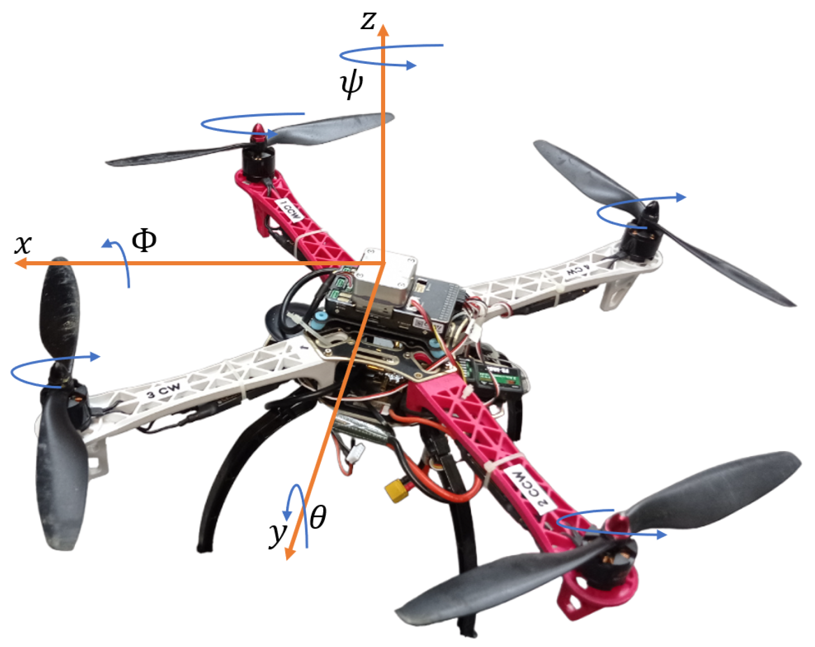
2. Dynamic Model of a UAV

Consider a 6-DOF dynamic model of a quadrotor UAV represented by translational dynamics (1) and rotational dynamics (2) [33]
η ¨ 1 = g z e + J 1 ( η 2 ) z e u m ,
ν ˙ 2 = I M 1 ( ( ν 2 × I M ν 2 ) + τ ) ,
where g and m are gravitational acceleration and mass, respectively. Vector η 1 = x y z is the inertial position of the quadrotor composed of forward (x), lateral (y), and vertical (z) motions. Moreover, ν 2 = p q r is the body frame angular velocity. We assume the UAV has four control inputs, where u is the translational thrust force in the body vertical direction and τ = τ p τ q τ r are the torques acting around the body rotational axes. Matrix I M = diag I x I y I z is an inertia matrix and z e = 0 0 1 is the unitary vector in the z direction. Although this study considers the quadrotor kinematics in the design, for simplicity of derivation, the attitude controller is designed in the local coordinate system and assumes zero cross-inertial terms. It is assumed that the position of the quadrotor can be measured using a set of external cameras configured as a positioning system. If this is not a feasible approach, however, SLAM-based technique can be used to estimate the quadrotor states.
The states of the UAV are represented as
η = η 1 η 2 , ν = ν 1 ν 2 ,
where η 1 = x y z is the inertial position of the quadrotor composed of forward (x), lateral (y), and vertical (z) motions; η 2 = ϕ θ ψ is the attitude represented by three Euler angles, roll ( ϕ ), pitch ( θ ), and yaw ( ψ ), also relative to the inertial frame; ν 1 = u v w is the body frame linear velocity; and ν 2 = p q r is the body frame angular velocity. There is tight coupling between the body and inertial frames expressed by the following transformations (3) and (4),
η ˙ 1 = J 1 ( η 2 ) ν 1
η ˙ 2 = J 2 ( η 2 ) ν 2
where the rotation matrices are expanded as
J 1 ( η 2 ) = cos θ cos ψ sin ϕ sin θ cos ψ cos ϕ sin ψ cos ϕ sin θ cos ψ + sin ϕ sin ψ cos θ sin ψ sin ϕ sin θ sin ψ + cos ϕ cos ψ cos ϕ sin θ sin ψ sin ϕ cos ψ sin θ sin ϕ cos θ cos ϕ cos θ J 2 ( η 2 ) = 1 sin ϕ tan θ cos ϕ tan θ 0 cos ϕ sin ϕ 0 sin ϕ cos θ cos ϕ cos θ .
Both ϕ and θ are constrained between π 2 and π 2 . Therefore, cos ϕ and cos θ are always non-zero. The coordinate frames are depicted in Figure 1. This UAV exhibits symmetry with respect to both the x and y axes, indicating that the center of gravity is located at the center of the UAV.
For a position stabilizing controller, the six inertial states, η , must be controlled with the set of four inputs ( u , τ p , τ q , τ r ) ; hence, this system is classically considered as under-actuated. In this study, the UAV is considered to have a variable payload mass. As a result, the total mass and inertial parameters of the system model will also vary. The mass of the UAV is assumed to be a piecewise function with unknown magnitude for the feedback control design.
For convenience, we can rewrite the attitude dynamic in (2) with an additional external disturbance in the linearly parameterized form as
ν ˙ 2 = w 1 f ( ν 2 ) + w 2 ζ + w 3 τ ,
where
w 1 = diag I y I z I x I z I x I y I x I y I z w 3 = I M 1 f ( ν 2 ) = q r p r p q T .
Within (5), w 2 ζ ( t ) is a time-varying external disturbance acting on the body frame, where w 2 is an unknown diagonal magnitude matrix and ζ ( t ) is a known function. This is fully defined during the simulation setup (37). The inertia I x ( t ) , I y ( t ) , and I z ( t ) parameters are also piecewise constant functions linked to the changing payload mass or position. Other unknown parameters, i.e., w 1 and w 3 are defined according to (6) and f ( ν 2 ) is a known function.

3. Proposed Control Design

The challenge being addressed is to design a stabilizing control system for the under-actuated and tightly coupled translational and attitude inertial states of a UAV. All parameters in the dynamic model are considered to be unknown time-varying parametric. We propose a nested control strategy for trajectory tracking of the quadrotor states. A virtual PD controller combined with an adaptive scheme is proposed to handle the translational position tracking the unknown time-varying mass in the outer loop. An adaptive control scheme is proposed to control the attitude dynamic in the presence of uncertain inertia and external disturbance parameters on the inner loop. The classical adaptive control approach using the certainty equivalence principle is extended to handle the multiple uncertainties. In this scheme, stability can be guaranteed even if the estimated parameters do not converge on the actual value.

3.1. Translational Control Design

The tracking controller for the translational dynamic can be designed by first defining the tracking error of the system as
η ˜ 1 = η 1 η 1 d ,
where η ˜ 1 and η 1 d are the error vector position and the desired vector position, respectively. The double integrator dynamics of (7) can then be written as
η ˜ ¨ 1 = K D η ˜ ˙ 1 K P η ˜ 1 .
By selecting K P and K D to be positive definite matrices, the system dynamics Equation (8) satisfies the Routh–Hurwitz stability criterion by having lim t η ˜ 1 ( t ) = 0 . The dynamics in Equation (8) can be expanded as
η ¨ 1 = η ¨ 1 d K D ( η ˙ 1 η ˙ 1 d ) K P ( η 1 η 1 d ) .
We define a virtual control input U = η ¨ 1 = U 1 U 2 U 3 T . Rearranging (1), we can generate
u m z e = J 1 1 ( η 2 ) ( U + g z e ) .
By expanding (10), we have
U 1 cos θ cos ψ + U 2 cos θ sin ψ ( U 3 + g ) sin θ = 0 ,
U 1 ( sin ϕ sin θ cos ψ cos ϕ sin ψ ) + U 2 ( sin ϕ sin θ sin ψ + cos ϕ cos ψ ) + ( U 3 + g ) sin ϕ cos θ = 0 ,
U 1 ( cos ϕ sin θ cos ψ + sin ϕ sin ψ ) + U 2 ( cos ϕ sin θ sin ψ sin ϕ cos ψ ) + ( U 3 + g ) cos ϕ cos θ = u m .
With the assumption that cos θ 0 , we can generate the pitch rotation from (11) as
θ = arctan U 1 cos ψ + U 2 sin ψ U 3 + g .
Squaring both sides of (10) yields
( u m z e ) T ( u m z e ) = ( J 1 1 ( η 2 ) ( U + g z e ) ) T ( J 1 1 ( η 2 ) ( U + g z e ) ) = ( U + g z e ) T ( U + g z e ) .
As a result
u m = U 1 2 + U 2 2 + ( U 3 + g ) 2
From (12) and (13), we have
u m sin ϕ = U 1 sin ψ U 2 cos ψ
By substituting (16) to (17), the roll rotation can be derived as rotation as
ϕ = arcsin ( U 1 sin ψ U 2 cos ψ U 1 2 + U 2 2 + ( U 3 + g ) 2 ) .
By following a similar method, we can compute
ϕ d = arcsin ( U 1 sin ψ d U 2 cos ψ d U 1 2 + U 2 2 + ( U 3 + g ) 2 ) θ d = arctan U 1 cos ψ d + U 2 sin ψ d U 3 + g ) ,
where ϕ d and θ d , and u d are the desired ϕ and θ , respectively.
From (1), we have
z ¨ = g + m 1 cos ϕ cos θ u .
The tracking dynamics error of z can be written as
e ¨ z d = g + m 1 cos ϕ cos θ u z ¨ d ,
where z d is the desired trajectory of z and e z d = z z d .
Let us denote ϵ 1 = e z d and ϵ 2 = e ˙ z d , then we can rewrite (21) as
ϵ ˙ = A ϵ ϵ + g e + g 1 + g 2 m 1 u
where
ϵ = ϵ 1 ϵ 2 , A ξ = 0 1 0 0 , g e = 0 z ¨ d g 1 = 0 g , g 2 = 0 cos ϕ cos θ .
The tracking control of translational dynamics is deemed to be successful if
lim t ϵ = 0 .
To achieve the objective stated in Equation (23), an adaptive scheme is designed as presented in Theorem 1.
Theorem 1
(Translational controller). Consider the translational dynamics of z (20). The tracking control is asymptotically achieved by proposing the following controller:
u = k a ϵ 1 k b ϵ 2 + m ^ ( cos ϕ cos θ ) 1 ( g + z ¨ d ) ,
where m ^ is generated using the following adaptation law:
m ^ ˙ = γ ϵ ϵ T P m ( g e + g 1 ) ,
for some positive constants γ ϵ > 0 , k a , and k b such that A m = 0 1 m 1 k a m 1 k b is Hurwitz and
P m A m + A m T P m = Q < 0 ,
where P m R 3 × 3 is the solution of a Lyapunov function.
Proof. 
The dynamics error of the closed-loop system (22) under the controller (24) can be written as
ϵ ˙ = A m ϵ + ( 1 m 1 m ^ ) ( g e + g 1 ) .
The mass of a UAV is always a positive integer. Then, it is easy to see that A m is Hurwitz for any positive k a and k b .
The Lyapunov function of (26) is selected to be
V ϵ , m ˜ = ϵ T P m ϵ + m ˜ 2 m γ ϵ ,
where m ˜ = m ^ m .
The time-derivative of the Lyapunov function (27) can be calculated as follows:
V ˙ ϵ , m ˜ = ϵ T P m ϵ ˙ + ϵ ˙ T P m ϵ + 2 m ^ ˙ m ˜ m γ ϵ = ϵ T P m ( A m ϵ + ( 1 m 1 m ^ ) ( g e + g 1 ) ) + ( A m ϵ + ( 1 m 1 m ^ ) ( g e + g 1 ) ) T P m ϵ + 2 m ^ ˙ m ˜ m γ ϵ = ϵ T ( P m A m + A m T P m ) ϵ + 2 ( 1 m 1 ( m ˜ + m ) ) ϵ T P m ( g e + g 1 ) + 2 m ^ ˙ m ˜ m γ ϵ = ϵ T Q ϵ 2 m 1 m ˜ ϵ T P m ( g e + g 1 ) + 2 m ^ ˙ m ˜ m γ ϵ = e ξ T Q e ξ .
From (25) and (26), we can see that ϵ and m ˜ are bounded. The second time-derivative of (27) is computed to show the convergence of the tracking dynamics error to zero as follows:
V ¨ ϵ , m ˜ = 2 ϵ T Q ϵ ˙ .
It follows from (26) that ϵ is uniformly bounded, and hence V ¨ ϵ , m ˜ is bounded. This implies that V ξ ˙ ( e ξ , m ˜ ) is uniformly continuous. Using Barbalat’s Lemma, ϵ converges to zero as t .This implies lim t z ( t ) z d ( t ) = 0 . The proof is thus completed. □

3.2. Attitude Control Design

In this section, the main contribution of this paper is explained. The presence of uncertain parameters in the attitude dynamics presents a challenging control problem. To solve this issue, an adaptive tracking control is extended to handle fully unknown parameters.
We define the desired trajectory as ν 2 d = p d q d r d T . The trajectory error can be calculated using e ν 2 = ν 2 ν 2 d . Therefore, the tracking dynamics error can be written as
e ˙ ν 2 = w 1 f ( ν 2 ) + w 2 ζ + w 3 τ ν ˙ 2 d .
The main objective of the tracking control is
lim t e ν 2 ( t ) = 0 .
We also denote the following structures of the system model:
E = diag ( e ν 2 ) , F ( ν 2 ) = diag ( f ( ν 2 ) ) Z = diag ( ζ ) , ν ˙ ̲ 2 d = diag ( ν ˙ 2 d ) .
The unknown matrices of w 1 , w 2 , and w 3 are estimated using w ^ 1 , w ^ 2 , and w ^ 3 , respectively, where w ˜ 1 = w ^ 1 w 1 , w ˜ 2 = w ^ 2 w 2 , and w ˜ 3 = w ^ 3 w 3 1 .
Theorem 2
(Rotational controller). Consider the attitude dynamic Equation (5). The objective of tracking control (31) is achieved by proposing the following controller:
τ = w ^ 3 K e ν 2 + w ^ 1 f ( ν 2 ) + w ^ 2 ζ ν ˙ 2 d ,
where w ^ 1 , w ^ 2 , and w ^ 3 are updated using the following adaptation laws
w ^ ˙ 1 = Γ 1 F ( ν 2 ) E , w ^ ˙ 2 = Γ 2 Z E , w ^ ˙ 3 = Γ 3 E ( K E + w ^ 1 F ( ν 2 ) + w ^ 2 Z ν ˙ ̲ 2 d ) ,
for some selection of positive definite Γ 1 , Γ 2 , Γ 3 , and K.
Proof. 
The dynamics error of a closed-loop system using Equations (5), (32) and (33) can be written as
e ˙ ν 2 = w 1 f ( ν 2 ) + w 2 ζ ν ˙ 2 d w 3 w ^ 3 ( K e + w ^ 1 f ( ν 2 ) + w ^ 2 ζ ν ˙ 2 d ) = w 1 f ( ν 2 ) + w 2 ζ ν ˙ 2 d w 3 ( w ˜ 3 + w 3 1 ) K e ν 2 + w ^ 1 f ( ν 2 ) + w ^ 2 ζ ν ˙ 2 d = K e ν 2 w ˜ 1 f ( ν 2 ) w ˜ 2 ζ w 3 w ˜ 3 K e ν 2 + w ^ 1 f ( ν 2 ) + w ^ 2 ζ ν ˙ 2 d .
We select the Lyapunov function for Equation (34) to be
V e ν 2 , w ˜ 1 , w ˜ 2 , w ˜ 3 = 1 2 e ν 2 T e ν 2 + tr 1 2 Γ 1 1 w ˜ 1 2 + 1 2 Γ 2 1 w ˜ 2 2 + 1 2 Γ 3 1 w 3 w ˜ 3 2 .
The time-derivative of (35) can generated by performing the following direct calculation:
V ˙ e ν 2 , w ˜ 1 , w ˜ 2 , w ˜ 3 = e ν 2 T e ˙ ν 2 + tr Γ 1 1 w ˜ 1 w ^ ˙ 1 + Γ 2 1 w ˜ 2 w ^ ˙ 2 + Γ 3 1 w 3 w ˜ 3 w ^ ˙ 3 = e ν 2 T K e ν 2 w ˜ 1 f ( ν 2 ) w ˜ 2 ζ w 3 w ˜ 3 K e ν 2 + w ^ 1 f ( ν 2 ) + w ^ 2 ζ ν ˙ 2 d + tr Γ 1 1 w ˜ 1 w ^ ˙ 1 + Γ 2 1 w ˜ 2 w ^ ˙ 2 + Γ 3 1 w 3 w ˜ 3 w ^ ˙ 3 = e ν 2 T K e ν 2 + e ν 2 T w ˜ 1 f ( ν 2 ) w ˜ 2 ζ w 3 w ˜ 3 K e ν 2 + w ^ 1 f ( ν 2 ) + w ^ 2 ζ ν ˙ 2 d + tr Γ 1 1 w ˜ 1 w ^ ˙ 1 + Γ 2 1 w ˜ 2 w ^ ˙ 2 + Γ 3 1 w 3 w ˜ 3 w ^ ˙ 3 = e ν 2 T K e ν 2 + tr ( Γ 1 1 w ˜ 1 w ^ ˙ 1 + Γ 2 1 w ˜ 2 w ^ ˙ 2 + Γ 3 1 w 3 w ˜ 3 w ^ ˙ 3 w ˜ 1 F ( ν 2 ) E w ˜ 2 Z E w 3 w ˜ 3 E K E + w ^ 1 F ( ν 2 ) + w ^ 2 Z ν ˙ ̲ 2 d e ν 2 T K e ν 2 .
From (33) and (34), we can see that e ν 2 , w ˜ 1 , w ˜ 2 , and w ˜ 3 are bounded. To show that the tracking error e ν 2 is driven asymptotically to zero, we calculate the second time-derivative of the Lyapunov function V e ν 2 , w ˜ 1 , w ˜ 2 , w ˜ 3 as
V ¨ e ν 2 , w ˜ 1 , w ˜ 2 , w ˜ 3 2 e ν 2 T K e ˙ ν 2 .
It is shown from (34) that e ν 2 is uniformly bounded, and hence V ¨ e ν 2 , w ˜ 1 , w ˜ 2 , w ˜ 3 is bounded. This implies that V ˙ e ν 2 , w ˜ 1 , w ˜ 2 , w ˜ 3 is uniformly continuous. Using Barbalat’s Lemma, lim t e ν 2 ( t ) = 0 . This completes the proof. □
It can be observed from the above formulation that the convergence of the estimation error of w ˜ 1 , w ˜ 2 and w ˜ 3 fully relies on e ν 2 ( t ) . The values of tr ( w ^ ˙ 1 T w ˜ 1 ) , tr ( w ^ ˙ 2 T w ˜ 2 ) and tr ( w ^ ˙ 3 T w ˜ 3 ) are not always negative; hence, the adaptation law (33) will always update itself, even it reaches the actual value of the unknown parameter. Conversely, updating will cease if e ν 2 ( t ) converges to zero. This means tracking control is asymptotically achieved, and even estimated parameters do not converge to the actual values.

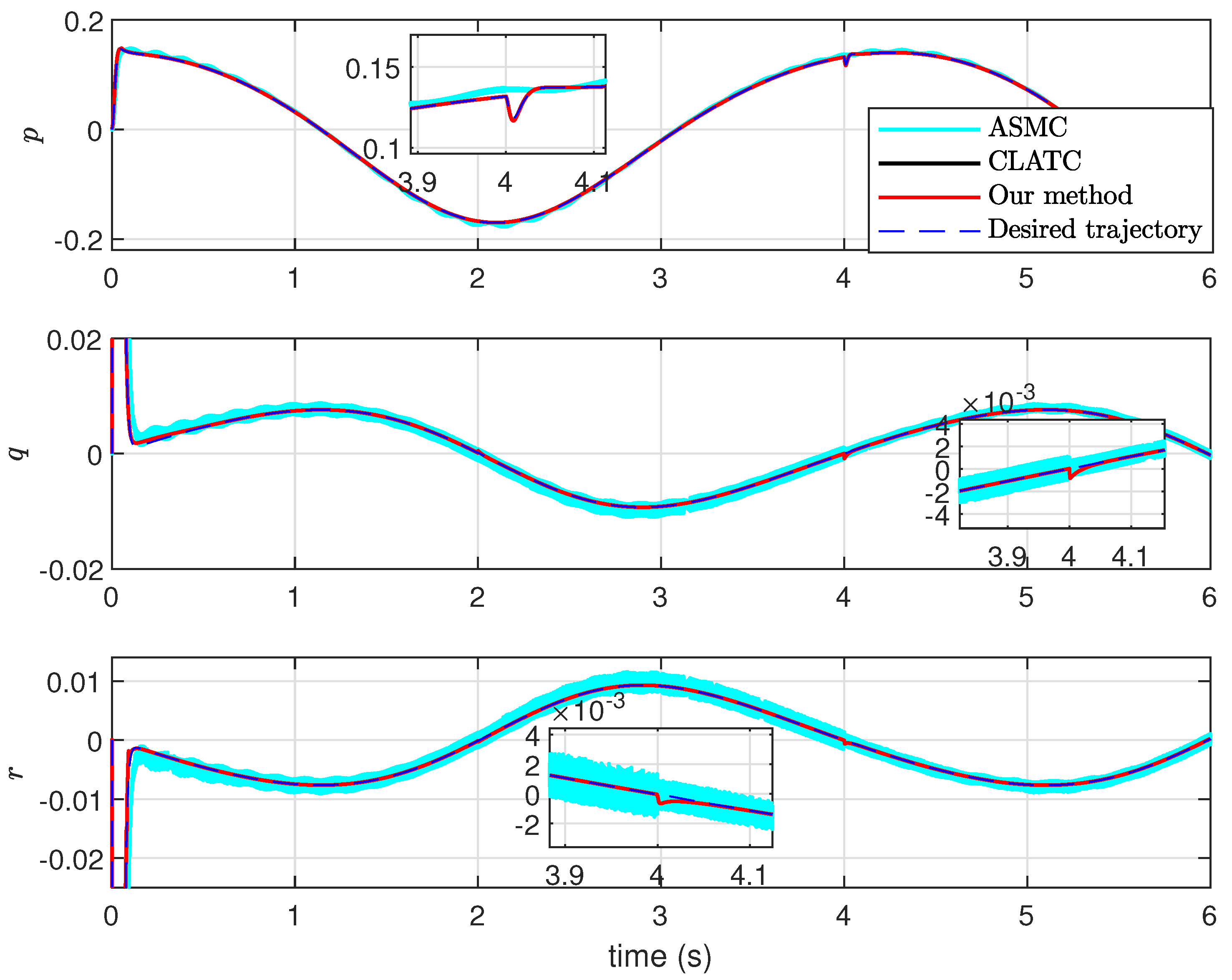
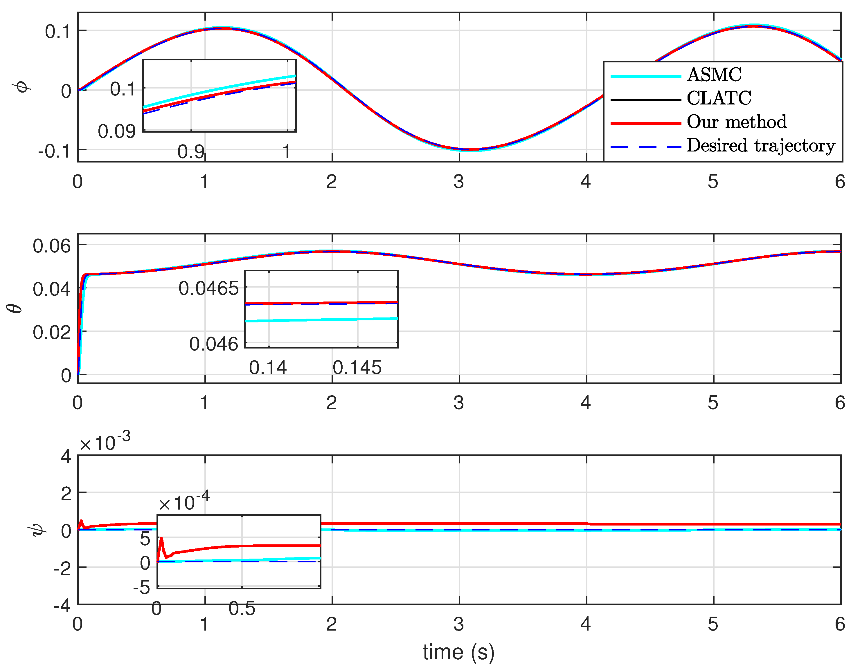
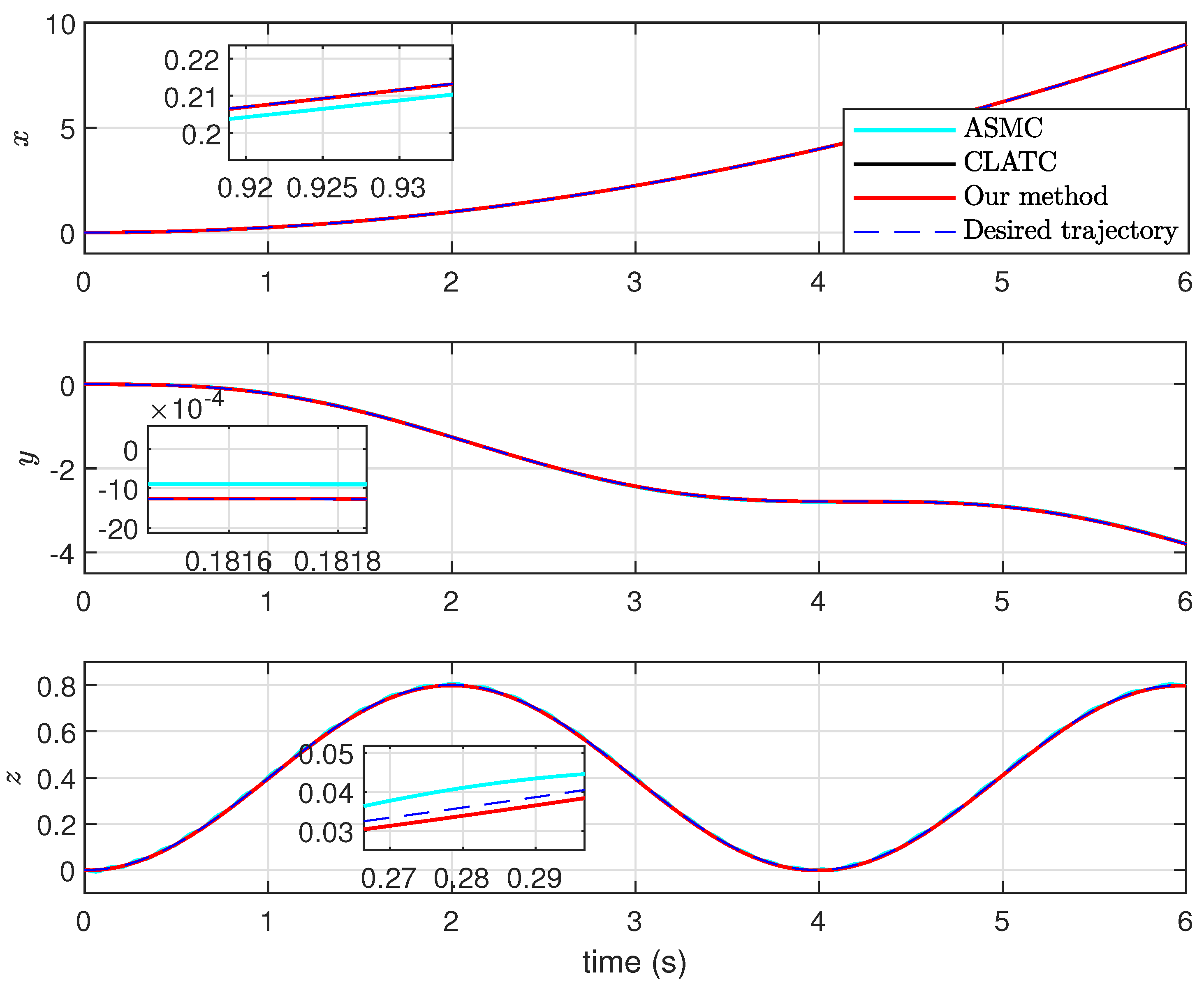
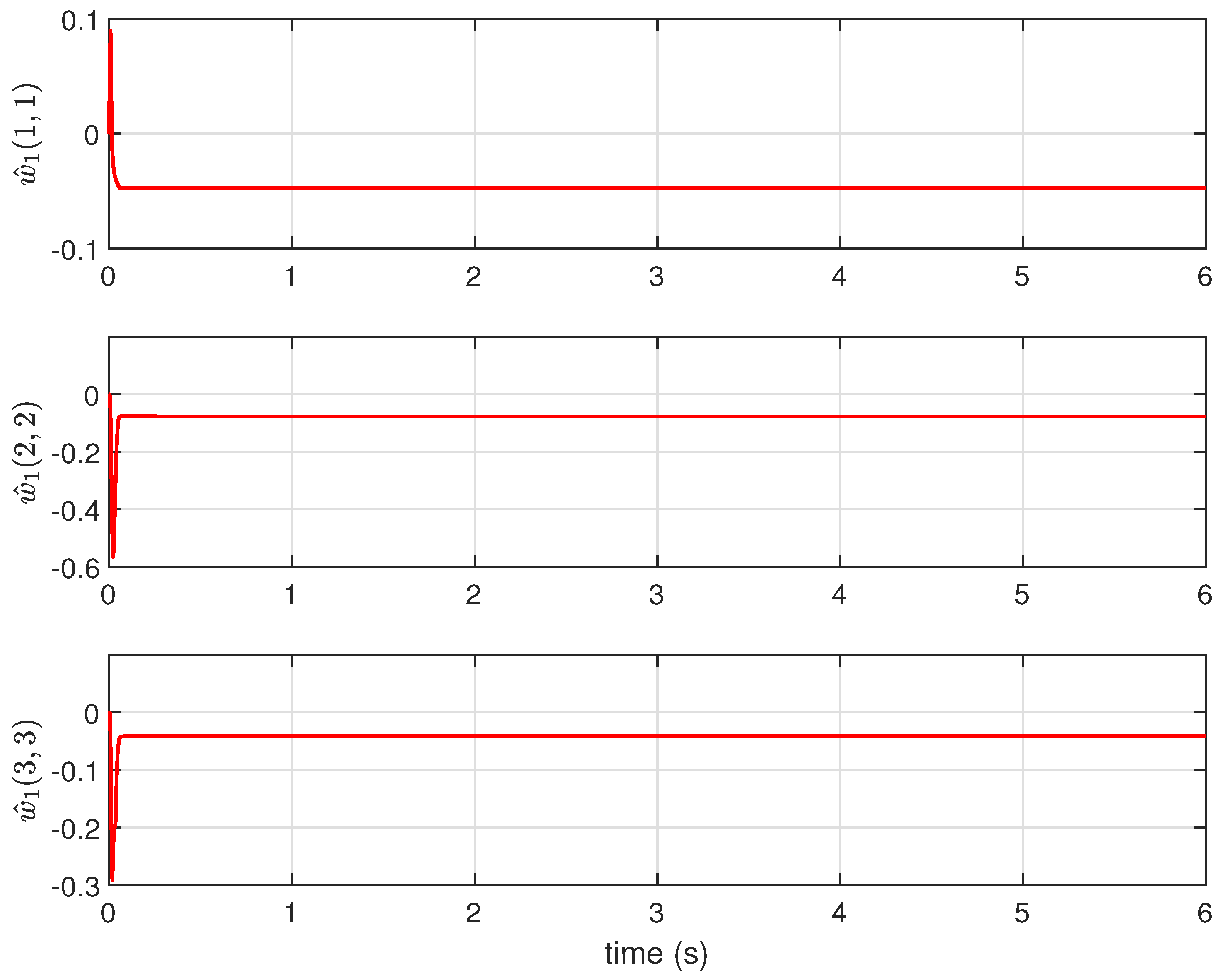
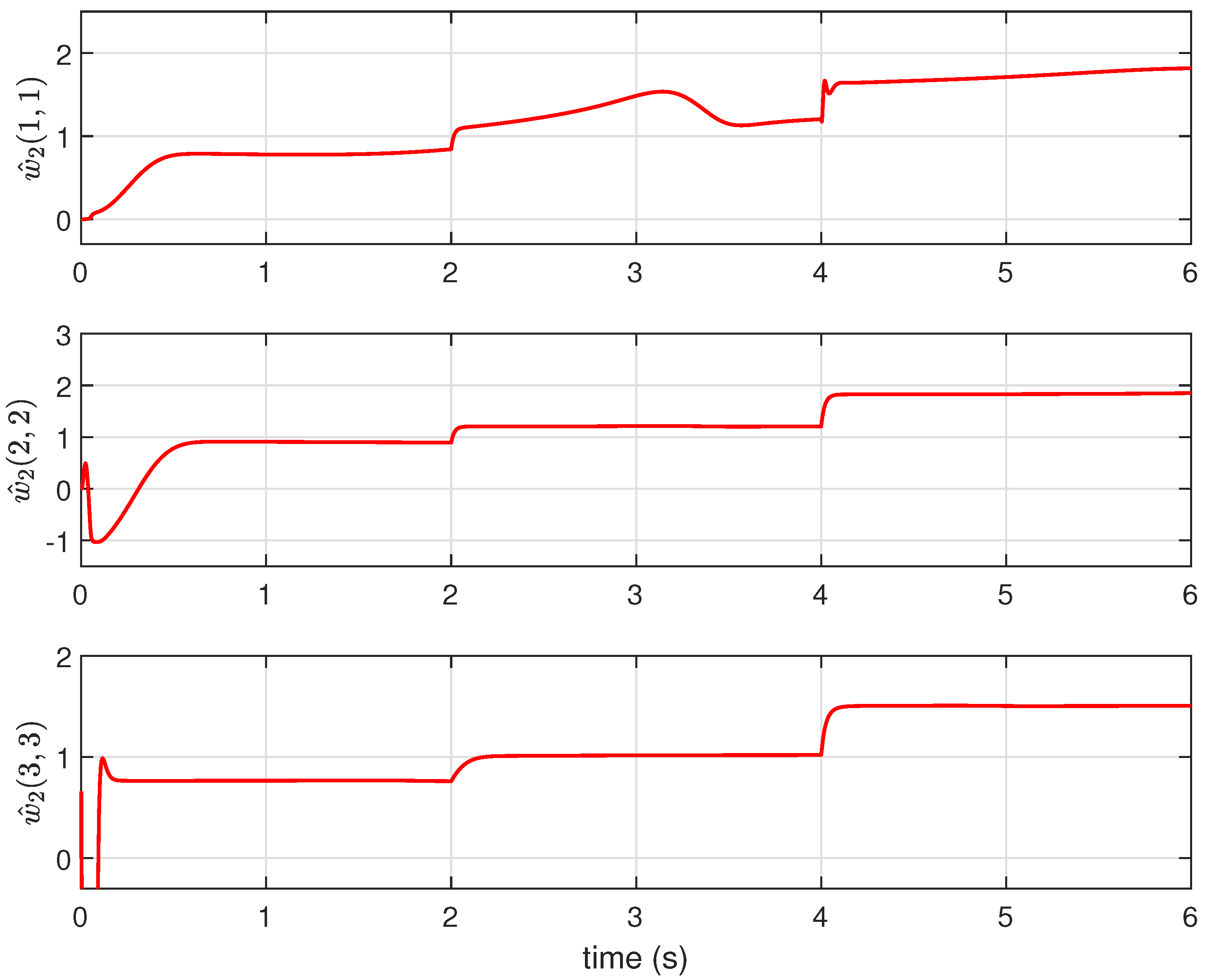
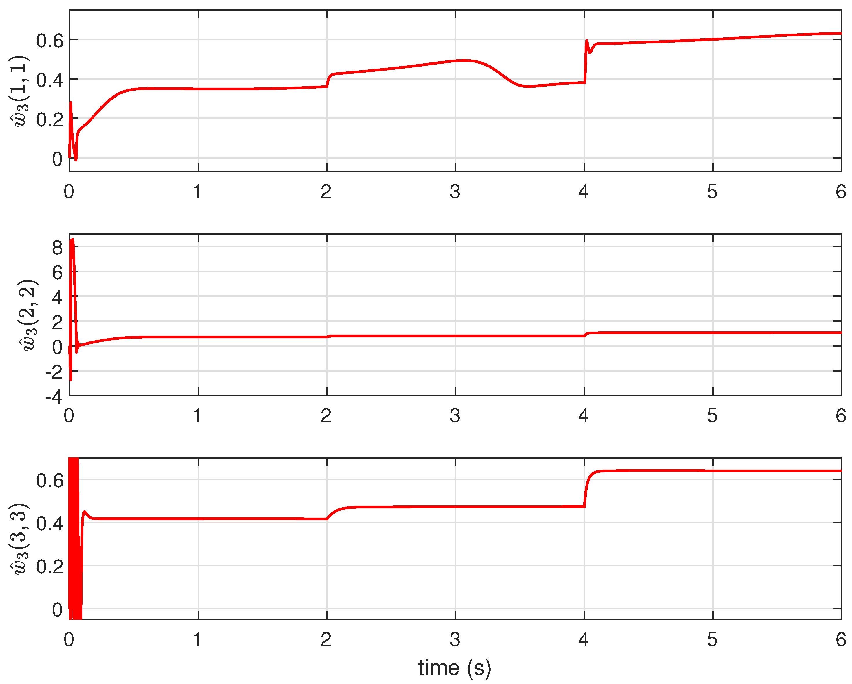
4. Simulation Results

The proposed strategy of a combined PD and adaptive control was assessed against other control design methods (closed-loop adaptive tracking control (CLATC) and adaptive sliding mode control (ASMC)) using a numerical simulation based upon a small UAV with initial parameters as listed in Table 1.
The gains of the PD controller were set as K P = K D = 500 I 3 , where I 3 R 3 × 3 was an identity matrix, thereby decoupling the control into parallel SISO systems. The adaptive scheme for transnational dynamics was designed according to Theorem 1 with the gains selected as follows:
k a = 500 , k b = 500 , γ ϵ = 100 , P m = I 2 .
The gains of the rotational motion control, designed according to Theorem 2, were selected to be
K = 1000 I 3 , Γ 1 = 10 4 I 3 , Γ 2 = 5 × 10 4 I 3 , Γ 3 = 10 4 I 3 .
The ‘unknown’ external disturbance was defined by
w 2 = diag ( 0.2 0.4 0.1 ) , ζ = sin ( t ) sin ( t ) cos ( t ) T ,
where the matrix w 2 was a piecewise constant function with elements increasing by 50 % every two seconds. To represent the UAV picking up a payload, all inertia parameters and mass were increased 50 % via a step function at t = 4 s.
To evaluate the effectiveness of the proposed schemes and compare the results with previous works, we used (1)–(4) for numerical analysis of the system states. This included x, y, and z as the states of the outer loop, and roll ( ϕ ), pitch ( θ ), and yaw ( ψ ), and their derivatives in the body frame (p, q, r). The controller was designed and simulated using Equations (24) and (32) for the altitude and attitude control, respectively. It was assumed that the UAV was starting with zero initial conditions for all states, which was interpreted as a static position and level orientation. All simulations were conducted in MATLAB/Simulink (2021b) environments with a small fixed step size of 2 × 10 5 s.
A variety of state trajectory and parameter adaptation results are illustrated in Figure 2, Figure 3, Figure 4, Figure 5, Figure 6, Figure 7, Figure 8, Figure 9, Figure 10 and Figure 11. Each simulation was run for 6 s, which was sufficient to allow settling of transients. The adaptive controller was able to drive all states of the UAV to follow the desired trajectory plot, as depicted in Figure 7. To compare the performance of our controller, we implemented two comparable methods, CLATC [34] and ASMC [35], under the same simulation setup and implementation framework.
The translation motion (Figure 4) showed accurate tracking, with results comparable to the other methods. The mass transition at t = 4 s showed very little disturbance because, as can be seen in Figure 5, the thrust control input u rapidly adapted to a new flight equilibrium, within 0.02 s. Comparing the control input trajectories, the new method was similar to CLATC and avoided the high-frequency oscillatory nature of ASMC. Although there were high-frequency and high-magnitude control values during the initial control adaptation phase 0 < t < 0.1 s, the transient control inputs during the later step-wise changes in disturbance and mass were small and likely to be a more realistically achievable actuation demand.
The tracking performance of all states is visualized in Figure 6 and Figure 7. Similarly to the control demands, there was a very large transient behavior during the initial adaptation phase. The transnational z errors indicated the stability of the new control scheme, but steady-state errors were manifested and increased in magnitude at the change in mass at t = 4 s.
Figure 8, Figure 9, Figure 10 and Figure 11 show the time progression of the adaptive control law states in (25) and (33). There were distinct transitions as the adaptation laws updated their values in response to the changing uncertain parameters. In most segments of the simulation, the state appeared to converge to steady values, but note that, as stated in Section 3, the tracking control stability was guaranteed, even if the internal state of adaptation laws did not converge to the actual value of the unknown parameter.
To quantitatively compare and assess the performance of the various controllers, we computed the fitness of the UAV motions using the formula:
fitness of ι ( % ) = 100 1 ι d ι ι E ( ι ) ,
where ι represents each state of the dynamic model of the UAV (with payload) and ι d is the desired trajectory. The mean value of ( ι ) over a defined time segment is denoted by E ( ι ) .
The fitness of the steady-state trajectories calculated from t = 2 s to t = 6 s can be seen in Table 2. The simulation results showed that our proposed control had a better performance in maintaining UAV motions with fully unknown parameters. It is worth noting that some chattering issues became apparent when employing ASMC, particularly during the initial settling phase, as depicted in Figure 2. This common issue is a well-known limitation of SMC methods, where abrupt control inputs can lead to oscillations and instability.
Furthermore, CLATC approach had a notable weakness in addressing time-varying mass, as discussed in [34]. This is because CLATC relies on an initial fixed mass value rather than estimating the mass through an adaptive law. Consequently, if the initial mass estimate substantially deviates from the actual mass, the performance of the translational controller may suffer. Additionally, CLATC lacks an adaptive control component to effectively handle external disturbances, further highlighting its limitations in addressing real-world scenarios where disturbances are prevalent.
An additional comparison metric was based on the total control efforts, as can be seen in Table 3. The control efforts were calculated as the time integral of the square of the control signals. Our method reduced the total control efforts to maintain UAV motions when compared to the other methods. The total thrust effort for CLATC was less than our method, which can be attributed to the insufficient control input used to handle the time-varying mass. This is why CLATC had the worst performance in controlling the translational motions compared to ASMC and our proposed controller.

5. Conclusions and Directions for Future Work

This article presents a new adaptive tracking control strategy for a 6-DOF of quadrotor type UAV with fully uncertain mass and inertial parameters. The inertial position tracking control was designed using a classical PD method and augmented with an additional adaptive controller designed to compute the total thrust for tracking control design, to robustly handle the presence of unknown time-varying mass caused by changes in the UAV payload. The tracking control problem for rotational motions was solved with a proposed new adaptive scheme. A rigorous stability analysis proved the proposed method can robustly control a UAV with fully unknown parameters along a tracking trajectory. The performance of the controller was demonstrated with several simulations and compared against other methods, with similar performance observed. One direction for future work is extending the proposed control design to more general time-varying unknown parameters, i.e., mass and inertia parameters. As a result, we need to generalize the current asymptotic stability proof for a more general time-varying payload UAV. In addition, considering more constraints in the design such as actuator saturation and obstacles would enhance the performance of the designed algorithm. Another future work could include expanding this design framework for multiple UAVs and validation via experimental applications. The communication between neighboring UAVs in this case would couple the effect of uncertainties through the Laplacian graph, which adds another layer of complexity to the whole problem.

Author Contributions

I.H.I.: Formal analysis, writing—original draft preparation, conceptualization, methodology, software, validation, visualization; K.W.: writing—review and editing; and A.M.: Conceptualization, project administration, funding acquisition, supervision, writing—review and editing. All authors have read and agreed to the published version of the manuscript.

Funding

This work was supported by the Engineering and Physical Sciences Research Council (EPSRC), grant number EP/R02572X/1, and National Centre for Nuclear Robotics.

Data Availability Statement

The article presents all essential data.

Acknowledgments

The authors are grateful for the support of the National Nuclear Laboratory (NNL) and the Nuclear Decommissioning Authority (NDA).

Conflicts of Interest

The authors declare no conflict of interest.

References

  1. James, M.R.; Carr, B.; D’Arcy, F.; Diefenbach, A.; Dietterich, H.; Fornaciai, A.; Lev, E.; Liu, E.; Pieri, D.; Rodgers, M.; et al. Volcanological applications of unoccupied aircraft systems (UAS): Developments, strategies, and future challenges. Volcanica 2020, 3, 67–114. [Google Scholar] [CrossRef]
  2. Radoglou-Grammatikis, P.; Sarigiannidis, P.; Lagkas, T.; Moscholios, I. A compilation of UAV applications for precision agriculture. Comput. Netw. 2020, 172, 107148. [Google Scholar] [CrossRef]
  3. Santamarina-Campos, V.; Segarra-Oña, M. Drones and the Creative Industry: Innovative Strategies for European SMEs; Springer Nature: Cham, Switzerland, 2018. [Google Scholar]
  4. Um, J.S. Drones as Cyber-Physical Systems; Springer: Singapore, 2019. [Google Scholar]
  5. Montazeri, A.; Can, A.; Imran, I.H. Unmanned Aerial Systems: Autonomy, Cognition and Control. In Unmanned Aerial Systems: Theoretical Foundation and Applications; Elsevier: Amsterdam, The Netherlands, 2020. [Google Scholar]
  6. Voos, H. Nonlinear control of a quadrotor micro-UAV using feedback-linearization. In Proceedings of the 2009 IEEE International Conference on Mechatronics, Malaga, Spain, 14–17 April 2009; pp. 1–6. [Google Scholar]
  7. Zhou, Q.L.; Zhang, Y.; Rabbath, C.A.; Theilliol, D. Design of feedback linearization control and reconfigurable control allocation with application to a quadrotor UAV. In Proceedings of the 2010 Conference on Control and Fault-Tolerant Systems (SysTol), Nice, France, 6–8 October 2010; pp. 371–376. [Google Scholar]
  8. Nemati, H.; Montazeri, A. Output Feedback Sliding Mode Control of Quadcopter Using IMU Navigation. In Proceedings of the 2019 IEEE International Conference on Mechatronics (ICM), Ilmenau, Germany, 18–20 March 2019; Volume 1, pp. 634–639. [Google Scholar]
  9. Huang, J.; Chen, Z. A general framework for tackling the output regulation problem. IEEE Trans. Autom. Control 2004, 49, 2203–2218. [Google Scholar] [CrossRef]
  10. Lewis, F.L.; Dawson, D.M.; Abdallah, C.T. Robot Manipulator Control: Theory and Practice; CRC Press: Boca Raton, FL, USA, 2003. [Google Scholar]
  11. Chen, Z. A novel adaptive control approach for nonlinearly parameterized systems. Int. J. Adapt. Control Signal Process. 2015, 29, 81–98. [Google Scholar] [CrossRef]
  12. Burrell, T.; West, C.; Monk, S.D.; Montezeri, A.; Taylor, C.J. Towards a cooperative robotic system for autonomous pipe cutting in nuclear decommissioning. In Proceedings of the 2018 UKACC 12th International Conference on Control (CONTROL), Sheffield, UK, 5–7 September 2018; pp. 283–288. [Google Scholar]
  13. Chen, X.; Chen, Z. Robust perturbed output regulation and synchronization of nonlinear heterogeneous multiagents. IEEE Trans. Cybern. 2016, 46, 3111–3122. [Google Scholar] [CrossRef] [PubMed]
  14. Li, S.; Wang, Y.; Tan, J.; Zheng, Y. Adaptive RBFNNs/integral sliding mode control for a quadrotor aircraft. Neurocomputing 2016, 216, 126–134. [Google Scholar] [CrossRef]
  15. Imran, I.H.; Montazeri, A. Distributed Robust Synchronization Control of Multiple Heterogeneous Quadcopters with An Active Virtual Leader. IFAC-PapersOnLine 2022, 55, 2659–2664. [Google Scholar] [CrossRef]
  16. Nemati, H.; Montazeri, A. Analysis and design of a multi-channel time-varying sliding mode controller and its application in unmanned aerial vehicles. IFAC-PapersOnLine 2018, 51, 244–249. [Google Scholar] [CrossRef]
  17. Eltayeb, A.; Rahmat, M.F.A.; Basri, M.A.M.; Eltoum, M.M.; El-Ferik, S. An improved design of an adaptive sliding mode controller for chattering attenuation and trajectory tracking of the quadcopter UAV. IEEE Access 2020, 8, 205968–205979. [Google Scholar] [CrossRef]
  18. Ghadiri, H.; Emami, M.; Khodadadi, H. Adaptive super-twisting non-singular terminal sliding mode control for tracking of quadrotor with bounded disturbances. Aerosp. Sci. Technol. 2021, 112, 106616. [Google Scholar] [CrossRef]
  19. Shankaran, V.P.; Azid, S.I.; Mehta, U.; Fagiolini, A. Improved Performance in Quadrotor Trajectory Tracking Using MIMO PIλ-D Control. IEEE Access 2022, 10, 110646–110660. [Google Scholar] [CrossRef]
  20. Narendra, K.S.; Annaswamy, A.M. Stable Adaptive Systems; Prentice Hall: Englewood Cliffs, NJ, USA, 1989. [Google Scholar]
  21. Anderson, B.D. Failures of adaptive control theory and their resolution. Commun. Inf. Syst. 2005, 5, 1–20. [Google Scholar] [CrossRef]
  22. Astolfi, A.; Karagiannis, D.; Ortega, R. Nonlinear and Adaptive Control with Applications; Springer Science & Business Media: London, UK, 2007. [Google Scholar]
  23. Hovakimyan, N.; Cao, C. L1 Adaptive Control Theory: Guaranteed Robustness with Fast Adaptation; SIAM-Society for Industrial and Applied Mathematics: Philadelphia, PA, USA, 2010; Volume 21. [Google Scholar]
  24. Lewis, F.L.; Zhang, H.; Hengster-Movric, K.; Das, A. Cooperative Control of Multi-Agent Systems: Optimal and Adaptive Design Approaches; Springer Science & Business Media: Berlin/Heidelberg, Germany, 2013. [Google Scholar]
  25. Liu, Y.; Jia, Y. Adaptive leader-following consensus control of multi-agent systems using model reference adaptive control approach. IET Control Theory Appl. 2012, 6, 2002–2008. [Google Scholar] [CrossRef]
  26. Qian, Y.Y.; Liu, L.; Feng, G. Distributed event-triggered adaptive control for consensus of linear multi-agent systems with external disturbances. IEEE Trans. Cybern. 2018, 50, 2197–2208. [Google Scholar] [CrossRef]
  27. Peng, Z.; Wang, D.; Zhang, H.; Sun, G.; Wang, H. Distributed model reference adaptive control for cooperative tracking of uncertain dynamical multi-agent systems. IET Control Theory Appl. 2013, 7, 1079–1087. [Google Scholar] [CrossRef]
  28. Ayala, H.V.H.; dos Santos Coelho, L. Tuning of PID controller based on a multiobjective genetic algorithm applied to a robotic manipulator. Expert Syst. Appl. 2012, 39, 8968–8974. [Google Scholar] [CrossRef]
  29. Das, A.; Lewis, F. Distributed adaptive control for synchronization of unknown nonlinear networked systems. Automatica 2010, 46, 2014–2021. [Google Scholar] [CrossRef]
  30. Das, A.; Lewis, F. Cooperative adaptive control for synchronization of second-order systems with unknown nonlinearites. Int. J. Robust Nonlinear Control 2011, 21, 1509–1524. [Google Scholar] [CrossRef]
  31. Elhaki, O.; Shojaei, K. A novel model-free robust saturated reinforcement learning-based controller for quadrotors guaranteeing prescribed transient and steady state performance. Aerosp. Sci. Technol. 2021, 119, 107128. [Google Scholar] [CrossRef]
  32. Gugan, G.; Haque, A. Path Planning for Autonomous Drones: Challenges and Future Directions. Drones 2023, 7, 169. [Google Scholar] [CrossRef]
  33. Imran, I.H.; Montazeri, A. An adaptive scheme to estimate unknown parameters of an unmanned aerial vehicle. In Proceedings of the 2020 International Conference Nonlinearity, Information and Robotics (NIR), Innopolis, Russia, 3–6 December 2020; pp. 1–6. [Google Scholar]
  34. Imran, I.H.; Stolkin, R.; Montazeri, A. Adaptive closed-loop identification and tracking control of an aerial vehicle with unknown inertia parameters. IFAC-PapersOnLine 2021, 54, 785–790. [Google Scholar] [CrossRef]
  35. Huang, T.; Huang, D.; Wang, Z.; Shah, A. Robust tracking control of a quadrotor UAV based on adaptive sliding mode controller. Complexity 2019, 2019, 7931632. [Google Scholar] [CrossRef]
Figure 1. Earth and body-fixed reference frame of the UAV.
Electronics 13 00347 g001
Figure 2. The time profile of p, q and r. Note the very small disturbance to the rotational rates when the mass of the vehicle changed at t = 4 . The large initial transient was due to the adaptive parameters converging.
Electronics 13 00347 g002
Figure 3. The time profile of ϕ , θ , and ψ . Since the disturbance profile comprises sinusoids acting symmetrically on the attitude rates, this manifested as a change in attitude.
Electronics 13 00347 g003
Figure 4. Profile of x, y, and z translational states. Due to the very rapid adaptation of all three control design strategies, there was a negligible effect on position.
Electronics 13 00347 g004
Figure 5. Time profile of the control inputs u and τ . After the initial transient, the proposed method produced a smooth signal similar to the CLATC methods, but with lower total control effort during the piecewise step changes in the disturbance and mass.
Electronics 13 00347 g005
Figure 6. Profile of the tracking error trajectories of positional and rotational states. A steady state offset was manifested in the vertical z position.
Electronics 13 00347 g006
Figure 7. Profile of x, y, and z in 3D showing the desired trajectory.
Electronics 13 00347 g007
Figure 8. Although the estimated mass m ^ was initially unknown, it quickly converged to near the correct values of 2.33 kg (Table 1 and 3.5 kg after the 50% increase).
Electronics 13 00347 g008
Figure 9. Profile of w ^ 1 .
Electronics 13 00347 g009
Figure 10. Profile of w ^ 2 .
Electronics 13 00347 g010
Figure 11. Profile of w ^ 3 .
Electronics 13 00347 g011
Table 1. The parameters of the quadcopter.
Parameter NameNotationValue
Massm2.33 kg
Gravity accelerationg9.8 m/s 2
Inertia of x-axis I x 0.16 kg·m 2
Inertia of y-axis I y 0.16 kg·m 2
Inertia of z-axis I z 0.32 kg·m 2
Table 2. The fitness of translational and attitude states of the UAV.
VariableCLATCASMCOur Method
p 99.2716 % 97.2657 % 99.9223 %
q 90.4057 % 90.3576 % 99.2270 %
r 92.9030 % 89.5838 % 99.3781 %
ϕ 98.8907 % 97.5545 % 98.5617 %
θ 99.8651 % 99.6649 % 99.9276 %
x 99.9659 % 99.9725 % 99.9973 %
y 99.9450 % 99.6831 % 99.9962 %
z 93.2952 % 99.3774 % 99.4648 %
average 96.8178 % 96.6824 % 99.5594 %
Table 3. The torque efforts of the controller.
VariableCLATCASMCOur Method
total effort of u 55.7138 2.4230 × 10 3 106.9775
total effort of τ p 17.2888 2.4419 × 10 5 9.8360
total effort of τ q 8.1215 × 10 3 4.9736 × 10 5 7.7383 × 10 3
total effort of τ r 1.1879 × 10 4 1.6565 × 10 5 1.4615 × 10 4
Disclaimer/Publisher’s Note: The statements, opinions and data contained in all publications are solely those of the individual author(s) and contributor(s) and not of MDPI and/or the editor(s). MDPI and/or the editor(s) disclaim responsibility for any injury to people or property resulting from any ideas, methods, instructions or products referred to in the content.

