Abstract
The growing demand for communication technology capable of providing high transmission rates in maritime environments has led to the exploration of the very high frequency (VHF) data exchange system (VDES) as a promising solution. The VDES, the integration of an automatic identification system (AIS), application-specific messaging (ASM), and VHF data exchange (VDE), offers improved transmission rates and stable connections compared with existing technologies. Although the VDES supports high transmission rates through various modulation and coding scheme (MCS) technologies, it lacks a standardized mechanism for controlling MCS parameters and relies on user algorithms for operation. In this paper, we introduce the maritime auto-rate fall-back (mARF) technology, designed to effectively address the challenges of maritime communication scenarios using the MCS framework provided by the VDES. mARF technology incorporates fast drop-out and recovery mechanisms to swiftly adapt to changing MCS types in the presence of deep nulls, a common occurrence in maritime communication environments. These adaptive thresholds for fast drop-out and recovery operations are dynamically learned using historical communication data. Through extensive simulations, we demonstrate the effectiveness of mARF in enhancing the MCS control capabilities of the VDES. Our results show a significant performance improvement of 18% compared to the existing model, validating the potential of mARF in optimizing maritime communication channels and supporting a high transmission rate.
1. Introduction
With the proliferation of Internet-of-Things (IoT) technology, there has been increasing demand for technologies that support communication connectivity in the maritime sector. In particular, the activation of maritime communication is essential for autonomous navigation, intelligent vessel, vessel tracking, and maritime information entertainment systems [1,2,3]. Various attempts have been made to address this issue using wireless communication. Traditional maritime communication relies on automatic identification system (AIS) technology to exchange navigational information [4]. However, the AIS has several limitations as it operates unidirectionally, making it difficult to confirm whether the receiving vessel has received the information. In addition, it is not mandatory for small ships to have AIS equipment, resulting in frequent communication gaps. Furthermore, the AIS must always be powered on, but it can be turned off, making it difficult to detect the location of a vessel. Moreover, the range for receiving signals from coastal infrastructure is limited to approximately 50 km, and the low transmission speed imposes constraints on applications beyond vessel positioning.
To overcome these limitations, various efforts have been made to leverage existing cellular mobile communication or Wi-Fi technologies for maritime communication. For example, Anwar et al. proposed maritime communication using LTE to provide coastal users with wide coverage and high data transmission rates [5]. Xu applied 5G technology to maritime communication to support higher data rates [6]. By contrast, Lopes et al. proposed maritime communication that achieved a communication range of 7 km at 1 Mbps using 802.11n-based Wi-Fi technology [7]. Campos et al. utilized the TV white space (TVWS) spectrum at 700 MHz to propose cost-effective and wide-bandwidth communication between ships and coastal infrastructure, while Teixeira et al. suggested long-range communication technology of up to 100 km using the TV spectrum [8,9]. However, these efforts have primarily applied existing cellular and WLAN technologies to the maritime communication environment and still have limitations regarding their widespread adoption in real maritime communication scenarios.
The VHF data exchange system (VDES) is a standard technology developed for next-generation maritime communication [10]. Through an amendment to the Safety of Life at Sea (SOLAS) convention, the International Maritime Organization (IMO) has mandated the incorporation of VDES technology for all passenger vessels, vessels over 300 tons engaged in international voyages, and vessels over 500 tons not engaged in international voyages. The VDES integrates an AIS, application-specific messaging (ASM), VHF data exchange—terrestrial (VDE-TER), and VHF data exchange—satellite (VDE-SAT), offering support for various applications compared to existing maritime communication technologies. It also supports link adaptation (LA) to achieve high-throughput link speeds, and the physical layer supported for link adaptation in the VDES has been presented in several studies [11,12]. However, while the VDES defines multiple modulation and coding scheme (MCS) technologies for LA operation, it does not provide definitions for algorithms on how to utilize these MCS technologies for LA operation. Additionally, there have been attempts to optimize link adaptation in the mmWave and Ka bands by expanding the frequency range. Representatively, Cao, Yuwen et al. and Echigo, Haruhi et al. tried to analyze signal quality using deep learning technology in the mmWave spectrum [13,14]. Also, Rinaldo, De Gaudenzi attempted to optimize channel capacity through MCS control in a satellite communications link [15,16,17]. Moreover, there is prominent research focused on enhancing channel capacity through the use of emerging technologies, including reconfigurable intelligent surfaces (RISs) technology and the optimization of orthogonal time–frequency space (OTFS) modulation for RISs [18]. However, there is still a lack of link adaptation techniques that can be used in the VDES, a maritime communication standard. In particular, despite the spread of the VDES through IMO regulations and the expansion of applications requiring high throughput using the VDES, there is a lack of research on link adaptation that optimizes VDES performance for the maritime communication environment.
In this study, we propose a new LA technique for optimizing throughput in a maritime communication environment using the VDES, referred to as the maritime auto-rate fall-back (mARF) technique. The mARF technique adapts MCS techniques based on communication success history, considering the characteristics of maritime communication environments. The proposed mARF supports fast recovery and a fast drop-out scheme, significantly enhances the channel utility, and achieves nearly 18% better performance than the existing LA technique. The remainder of this paper is organized as follows: Section 2 provides an explanation of the VDES and the maritime communication environment; Section 3 presents the proposed mARF technique; Section 4 offers performance evaluations; and Section 5 concludes the paper.
2. VDES and Maritime Wireless Channel
2.1. VHF Data Exchange System
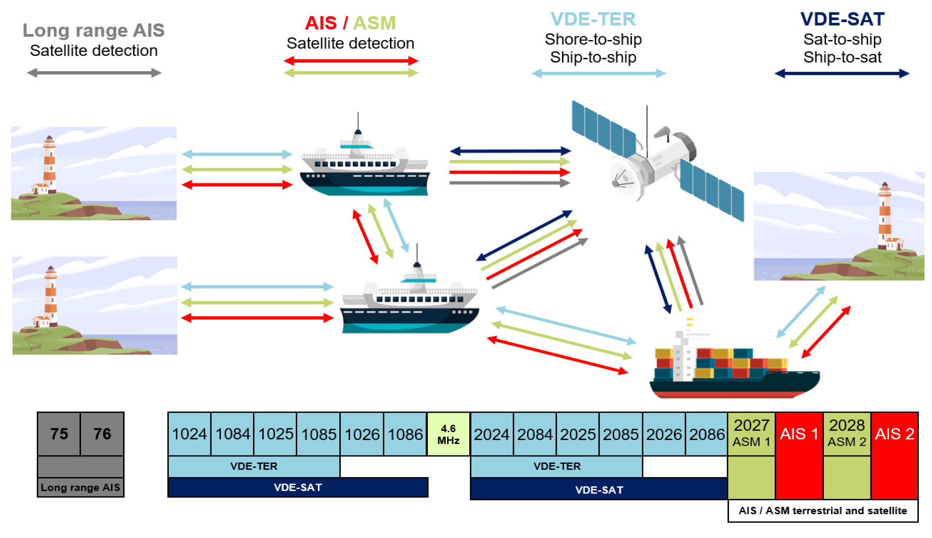
The VDES contains four sub-systems: AIS, ASM, VDE-TER, and VDE-SAT. Each system has an identified purpose, and is designed based on its target applications. The AIS provides broadcasting communication for the vessel position, course, and speed to avoid collisions. The AIS has the highest priority in the VDES, and other subsystems are meticulously structured to prevent adverse impacts on the AIS operation. The ASM offers robust message delivery reliability and comprehensive message acknowledgement support, including satellite up-link capability. Two dedicated 25 kHz simplex channels are allocated for both existing and defined automatic systems for maritime safety, outlined by the International Association of Marine Aids to Navigation and Lighthouse Authorities (IALA) and the IMO. The VDE-TER encompasses a 100 kHz duplex channel designed to accommodate data exchange needs that require a greater capacity than that provided by the ASM.
Figure 1 depicts a VDES functions and the frequency use case [19]. In Figure 1, the numbers 75, 76, 1024, etc., on the x-axis represent channel numbers in the VDES, and there is a 4.6 MHz gap between channels 1086 and 2024. The vessels can fully harness the potential of this duplex channel when communicating with coastal stations. VDE-SAT incorporates a satellite designed to facilitate bidirectional communication in high seas and remote areas where shore station coverage is lacking. The VDES concept was originally proposed to address emerging indications of overload of the VHF data link (VDL) of the AIS and simultaneously enable wider seamless data exchange for e-navigation, potentially supporting the modernization of the global maritime distress and safety system (GMDSS). The VDES can support the increasing communication requirements identified through the development of e-navigation, as documented in the e-navigation strategic implementation plan (SIP) IMO MSC.1/Circ.1595 [20]. E-navigation aims to enhance pier navigation and related services for safety and security at sea and to protect the marine environment. E-navigation seeks to enhance maritime safety by simplifying and harmonizing information. Additionally, e-navigation seeks to facilitate and increase the efficiency of maritime trade and transport by improving information exchange. The VDES concept recognizes the parallel work being carried out related to maritime services in the context of e-navigation, formerly known as the maritime service portfolio (MSP).
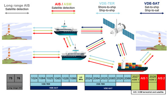
Figure 1.
VDES functions and frequency use case.
2.2. Maritime Wireless Channel
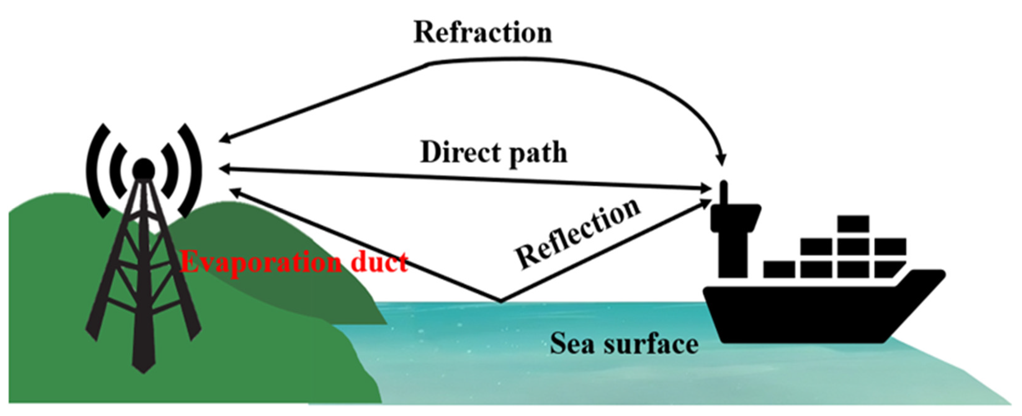
As a traditional logarithmic path loss model for wireless communication such as LTE, Wi-Fi cannot represent the local oscillations owing to the rays reflected from the sea surface and extra refraction owing to the evaporation duct in the maritime wireless channel. As shown in Figure 2, RF propagation in the maritime environment is affected by various factors, such as antenna height changes due to waves and effects from evaporation ducts. Therefore, several studies have been conducted on wireless channel models for over-the-sea communication [21,22,23,24,25]. YH Lee et al. focused on the evaporation duct phenomenon, which occurs owing to variations in humidity across the air–sea boundary. Moreover, channel modeling was performed in such an environment; special attention was paid to refraction caused by a possible evaporation duct as well as direct rays and sea surface-reflected rays [21]. K. S. Zaidi et al. established the statistical distribution of path loss based on varying distances from those in the literature, proposed a 2-P probability distribution model, and proved that it fits well in marine communication channel modeling [25]. J. Wang et al. proposed a practically usable deterministic path loss model, demonstrating its ability to sufficiently simulate the maritime wireless channel environment [26,27]. In this study, we utilize the two-ray path loss and three-ray path loss models proposed and validated in [26,27], which are expressed in Equations (1)–(3).
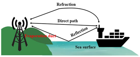
Figure 2.
RF propagation in the maritime environment.
In Equation (1), and denote the heights of the transmitter and receiver antennas, respectively. Moreover, indicates the wavelength of the carrier signal, and indicates the distance between the transmitter and receiver.
In Equation (2), denotes the height of the effective evaporation duct, and ∅ is calculated as follows:
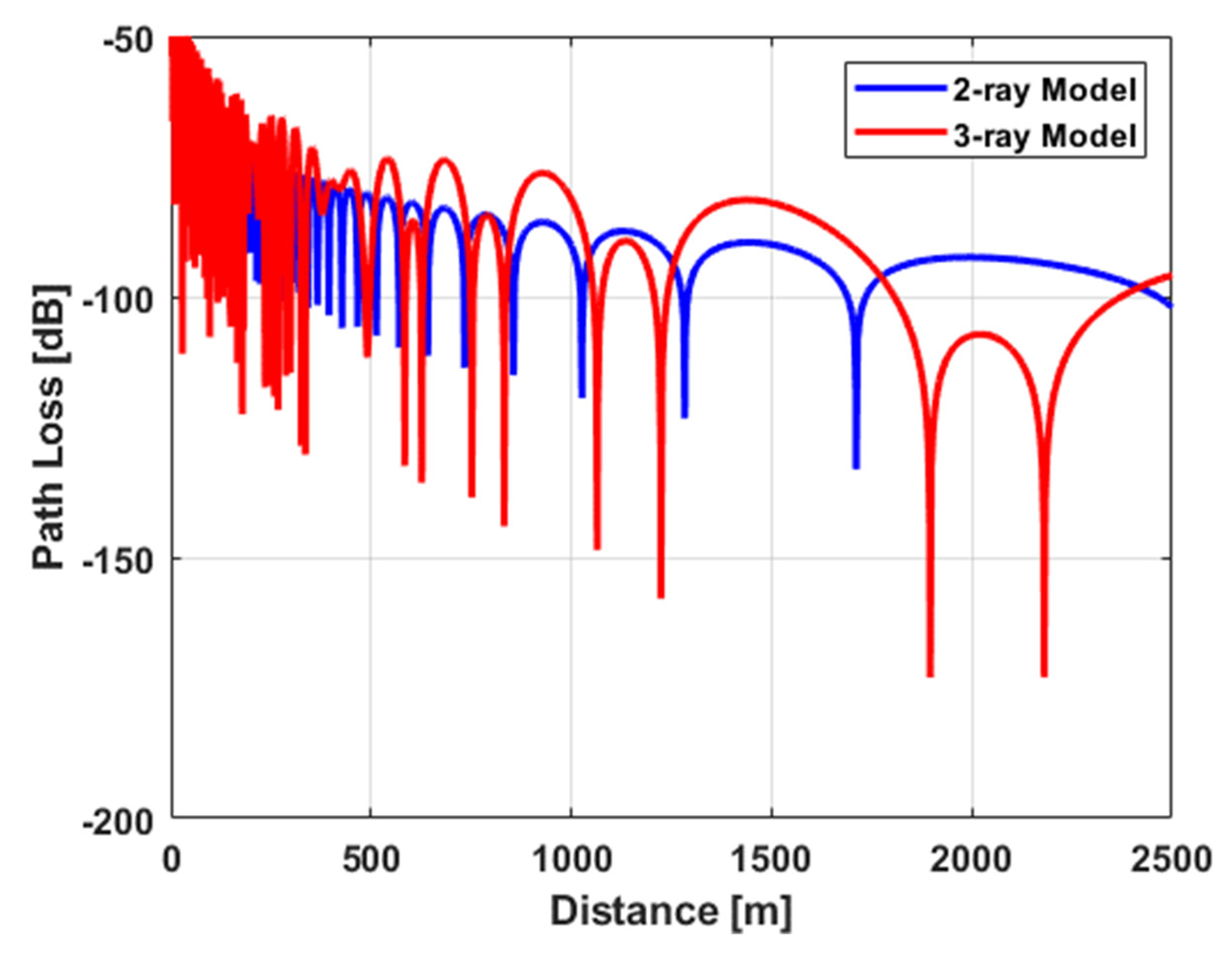
Figure 3 illustrates the signal path loss as a function of distance, utilizing both the two-ray and three-ray models, and allows us to observe the phenomenon of a deep null (sudden signal drop).
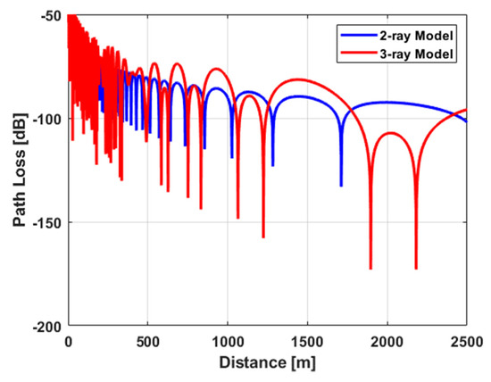
Figure 3.
Two-ray and three-ray signal path loss characteristics in marine wireless channel.
3. New Link Adaption Technique in Maritime Environment
3.1. Link Adaptation
The VDES provides additional support for adaptive modulation and coding (AMC) techniques. In addition, the LA technique involves the selection of appropriate modulation and coding rates based on the prevailing channel conditions using AMC algorithms. For instance, communication errors will occur in scenarios where a ship is located a considerable distance from the coastline and consequently experiences weakened signal reception from a coastal station. When communication errors occur, the LA technique in the VDES should change the AMC profile to guarantee reliable communication. However, if a ship is close to a coastal station, the AMC profile must be changed to increase channel efficiency. In other words, proper selection of the AMC profile in the LA technique is crucial for increasing channel efficiency based on appropriate channel estimation.
The LA technique should be operated based on appropriate channel estimation. Therefore, a channel estimation technology that can represent the channel conditions under which the LA technique operates is vital. The representative channel estimation method for the LA technique utilizes a channel reference metric, such as the received signal strength indicator (RSSI) [28]. However, it cannot accurately predict the channel capacity for imminent transmission in maritime communication environments. This is because the maritime communication environment, unlike the general land communication environment, is a channel environment in which periodic RSSI detection is difficult, and special phenomena (deep nulls) occur. Figure 3 shows the modeling of the maritime communication channel environment based on the distance. As shown in Figure 3, the signal is attenuated with distance, but it can be observed that the signal is rapidly lowered owing to rays reflected from the sea surface and extra reactions by the evaporation duct. In other words, in a situation where signal attenuation occurs rapidly, it is difficult to acquire the RSSI in a short period; therefore, a new LA technique is needed.
3.2. Maritime Auto-Rate Fall-Back
Two approaches to LA techniques can be used to adjust the MCS: the auto-rate fall-back (ARF) technique, which adjusts the MCS profile based on the historical communication success record, and the receiver-based auto-rate (RBAR) technique, which measures the actual received signal strength to adjust the MCS profile [28,29]. The RBAR technique has an advantage over ARF in that it determines the MCS profile based on the actual received signal strength, providing a more accurate channel condition-based MCS profile decision. However, it incurs overheads because it involves measuring the signal strength of the MCS profile for each communication instance. Additionally, it has limitations, as it may inaccurately interpret channel conditions owing to momentary fading phenomena that occur during signal measurements. Therefore, in environments such as maritime communication, where continuous communication is not maintained and deep nulls are present, utilizing the ARF based on historical communication records may be a more efficient approach.
The existing ARF technique considers the current channel condition to be excellent if ACK signals for the transmitted data are received within the timeout period; otherwise, it is assumed that the channel condition is not excellent. In other words, when acknowledgments of multiple data transmissions are received, the channel condition is deemed to be sufficiently excellent, prompting a change in the MCS profile. However, existing ARF techniques are designed for terrestrial communication; therefore, they are ineffective in maritime environments. In maritime communication, which is characterized by significant signal distortion, particularly deep null path loss, as opposed to terrestrial wireless communication, it is imperative to introduce an optimized LA technique. Thus, we propose a new ARF technique capable of addressing deep nulls, called the mARF technique.
The mARF technique was applied to the VDE-TER in the VDES, and the MCS profiles used in the VDES-TER are listed in Table 1. As indicated in Table 1, the VDE-TER provides nine different MCS profiles, and each profile is identified through the link configuration ID. In addition, each MCS technique has a different packet error rate (PER), and an appropriate link configuration ID must be set based on the channel situation. The PER for each link configuration ID is defined as follows.
where denotes the symbol length and denotes the symbol error rate, which is determined by the modulation and coding rates. Table 2 describes the SER function as modulation scheme.

Table 1.
VDE-TER configuration parameters.

Table 2.
SER function as modulation scheme.
Consequently, we can derive the throughput using
where indicates the symbol rate; indicates the number of bits in each modulation symbol; indicates the channel coding efficiency; indicates the total data length of each packet; and indicates the data overhead, such as the header packet of each packet [30,31].
One critical consideration for the design of mARF is the occurrence of a phenomenon known as “deep null” in maritime communication channels, where signal attenuation occurs rapidly, and then, suddenly disappears. In other words, a technique that can address the deep null phenomenon is required. When experiencing a deep null, there is sharp signal attenuation; therefore, the most reliable communication technique must be used. Thus, mARF first determines that communication errors occur because of signal attenuation caused by the deep null phenomenon, not by data collision. Consequently, even if a single communication error occurs, mARF performs a fast drop-out operation. For example, when a communication error occurs once in link ID 19, it immediately switches to the lowest MCS profile—link ID 13—to ensure stable communication. The mARF technique increases the MCS profile as the channel conditions improve to enhance the channel utilization. As described earlier, communication situations deteriorate rapidly in maritime communication channels because of the deep null phenomenon; however, paradoxically, they can also improve dramatically. Thus, when using the most reliable MCS profile for communication and observing n consecutive successful communications, the algorithm switches to the next profile for high-throughput communication. In addition, after achieving consecutive successful communications in the current MCS profile, it changes to the next higher MCS profile. We define the process of increasing the MCS profile as fast recovery. Algorithm 1 shows the pseudocode of the algorithm used in mARF to direct the rate of increase in the transmitter rate with fast recovery.
| Algorithm 1. Pseudocode for MCS adaptation procedure in mARF. |
| MCSnext:= MCScurrent; MCShigh:= the MCS type higher than MCScurrent; MCSlow:= the lowest MCS type among MCS profile; MCSthr:= MCStype3 attempt_success:= 0; while (MCSnext:= MCScurrent || attempt_success == 0) { if (xmit_success(MCSnext) == 0) then MCSnext:= MCSlow /rate decreasing attempt by fast drop-out/ else { attempt_success:= attempt_success + 1; if (attempt_success ≥ n) then { MCSnext:= MCShigh /rate increasing attempt by fast recovery/ break; }} if (MCSnext == MCSthr) then attempt_success:= attempt_success/2; else attempt_success:= attempt_success; } |
In addition, n, which is an MCS-changing counter, can be adaptively updated based on previous communication history. When updated adaptively, it can be updated through the weight relationship between the previous n values, as shown in Equation (6):
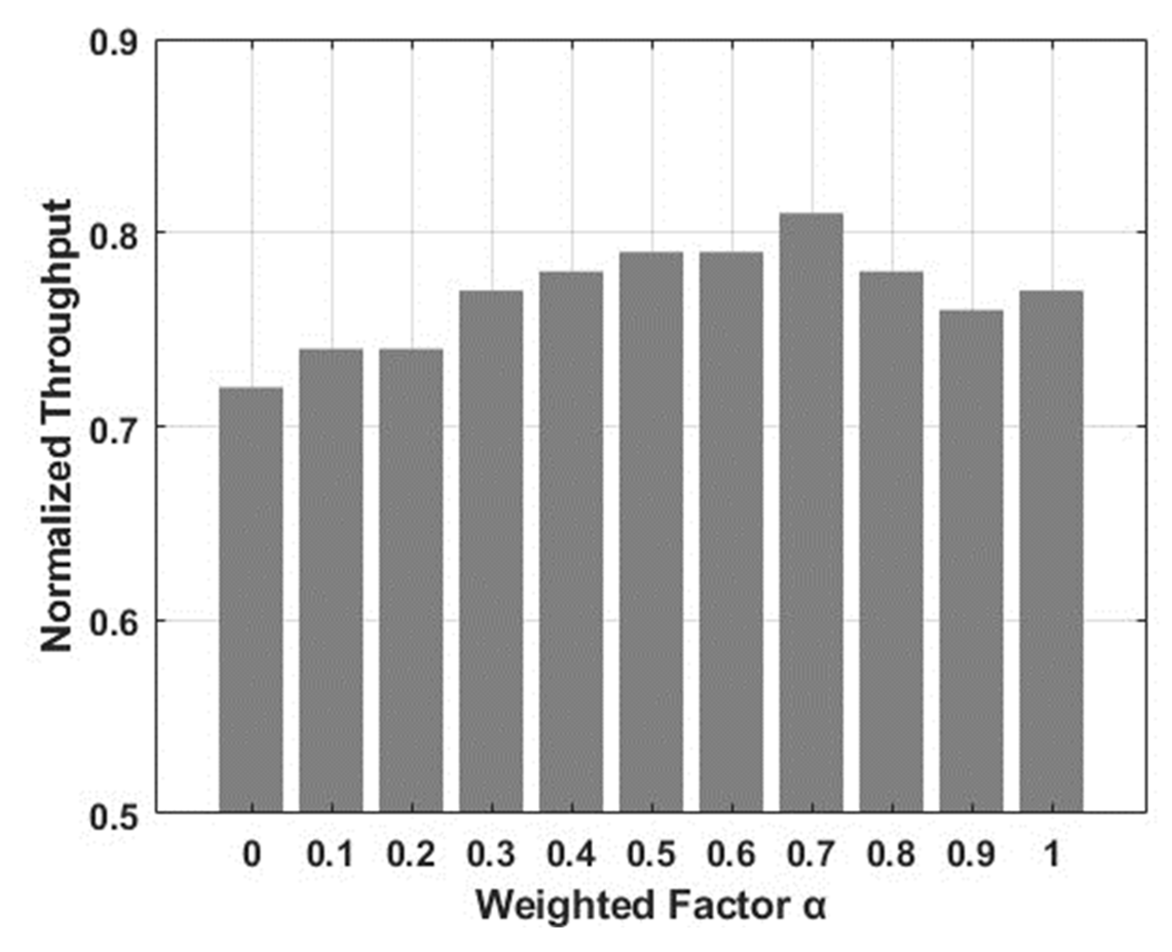
where is a weighted factor and ranges between 0 and 1. To determine the value, we performed the simulation by changing from 0 to 1 in 0.1 increments, and confirmed that giving 70% weight to the immediately previous value had the best performance. Thus, the mARF technique uses a default value of 0.7. Additionally, the value can be changed by the user. In addition, the mARF technique determines the MCS profile based on existing communication history and adjusts the MCS change threshold, so it is very efficient as it can greatly reduce the computational complexity for MCS change in systems such as the VDES with a limited number of usable MCS profiles.
4. Performance Evaluation
In this section, we evaluate the mARF technique for various maritime channels. For this purpose, we developed a VDE-TER simulator using MATLAB and implemented mARF and existing ARF techniques. The existing ARF technique was used to increase the MCS profile when communication was successful 10 times and to lower the MCS profile when communication failed 2 times continuously. The PHY layer parameters for the VDE-TER, which were employed in constructing the simulator, are listed in Table 3.

Table 3.
Simulation parameters for VDE-TER.
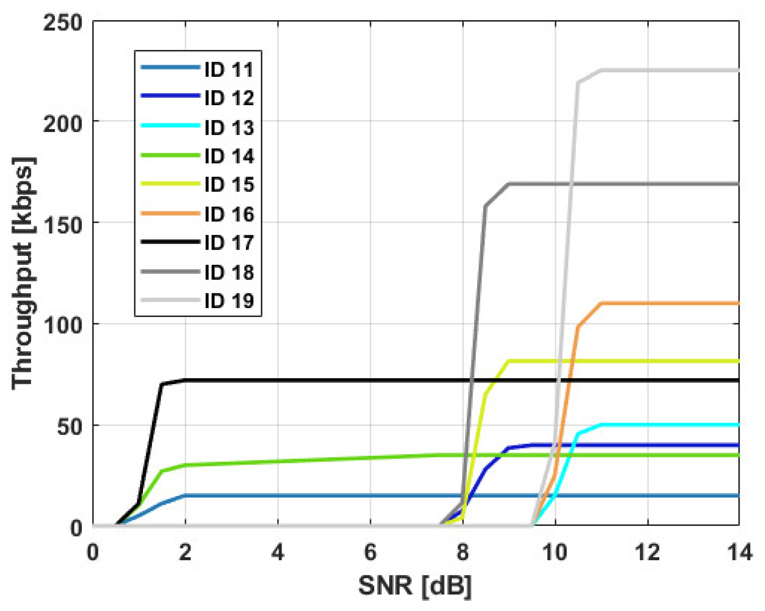
First, we simulated the performance of the VDE-TER system while changing the physical layer parameters to verify the performance of the VDE-TER in an ideal environment which is the AWGN case without a deep null phenomenon. Figure 4 shows the system throughput of the VDE-TER. As shown in Figure 4, it can be verified that a higher throughput can be obtained using higher ID numbers in the channel environment, primarily because higher ID numbers have a higher channel bandwidth (BW), FEC rate, and modulation degree. It is confirmed that the optimal ID number depends on the channel environment represented by the SNR. That is, when using a BW fixed at 100 kHz, it can be confirmed that IDs 17, 18, and 19 must be changed based on the signal-to-noise ratio (SNR).
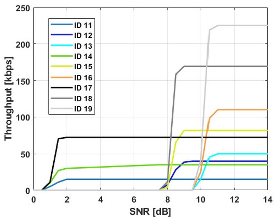
Figure 4.
VDE-TER throughput vs. SNR.
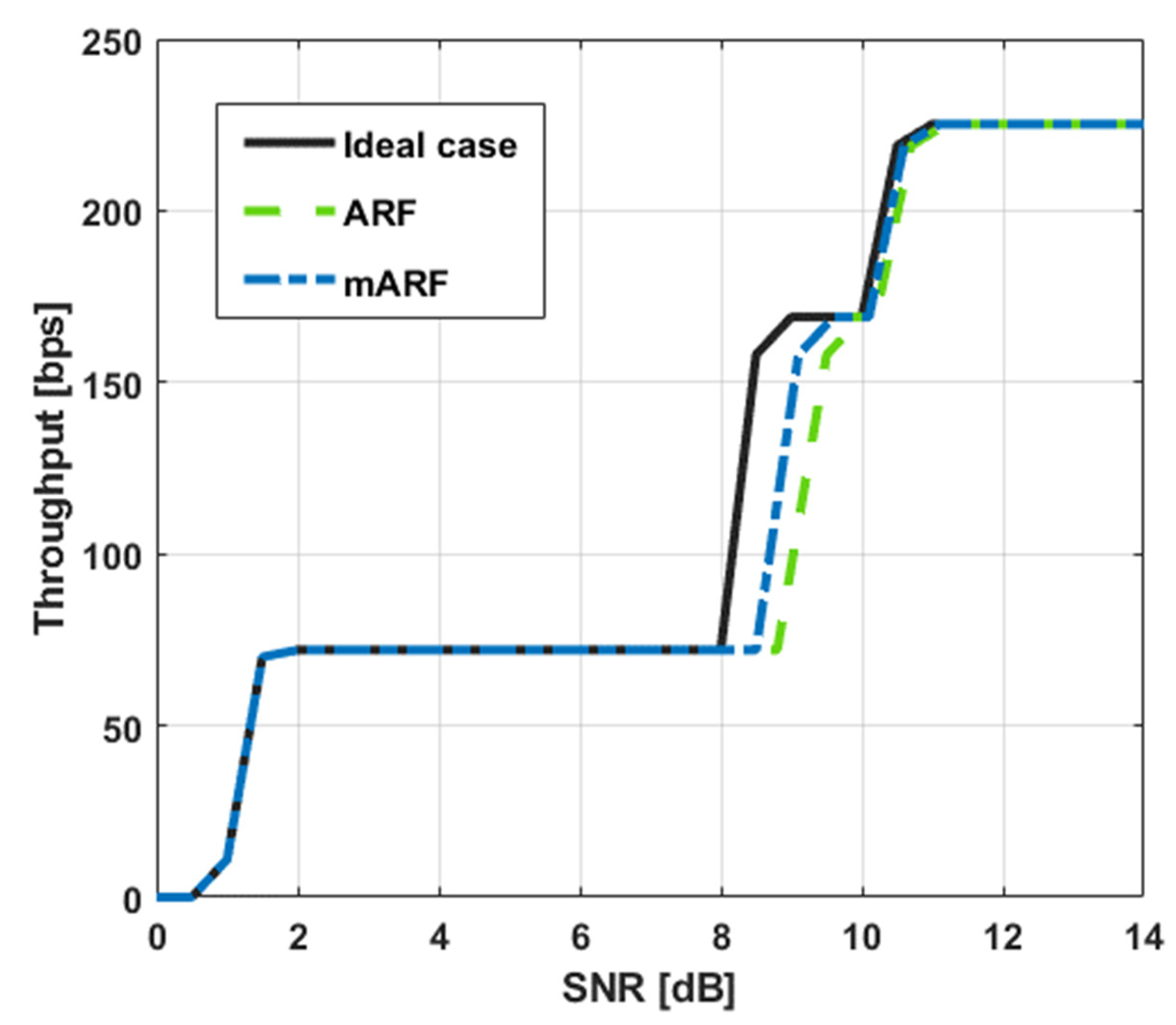
For comparison under identical conditions, we evaluated mARF performance in an environment in which the bandwidth was fixed at 100 kHz. At this time, to apply the phenomenon of rapid signal attenuation in the maritime environment, the random deterioration phenomenon of SNR was applied in the performance evaluation based on Equations (1)–(3). First, a performance evaluation was performed in a two-ray channel model environment, and the throughputs of the ideal case, traditional ARF, and mARF were evaluated. As shown in Figure 5, it can be confirmed that mARF has a performance closer to the ideal case than ARF, even when a deep null phenomenon occurs that results in a rapid SNR change.
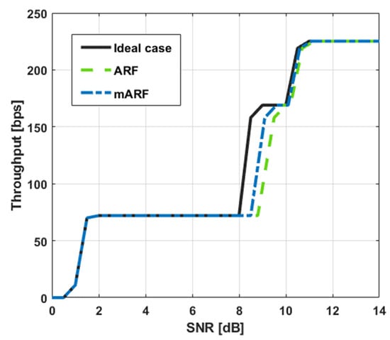
Figure 5.
Comparison of throughputs in two-ray channel model.
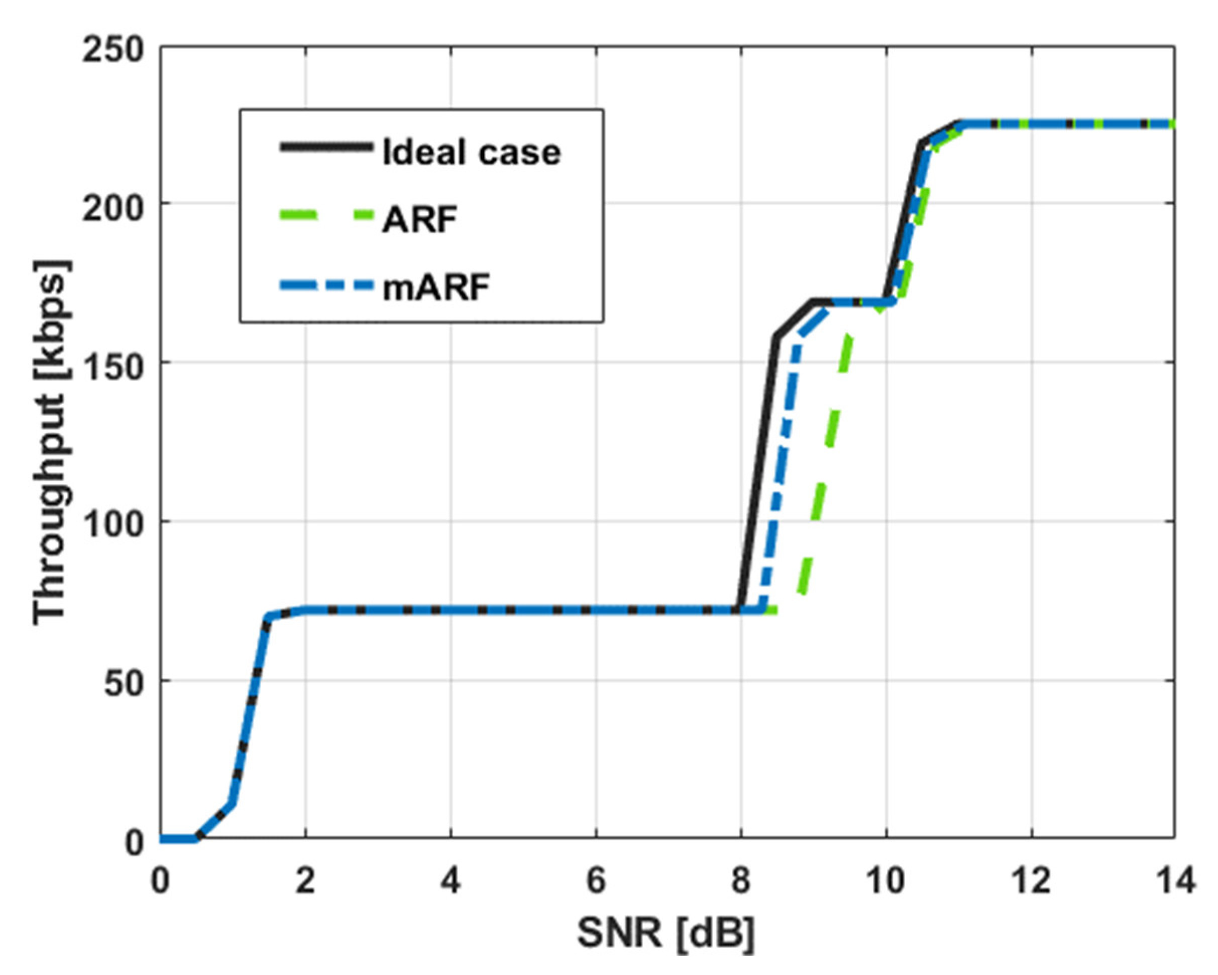
Figure 6 shows the results that represent the throughput of the ideal case and the techniques compared with the SNR in a three-ray channel environment. As shown in Figure 6, mARF follows the channel capacity in response to the channel capacity of the ideal case, and it can be confirmed that it has a performance close to that of the ideal case, even if a deep null phenomenon occurs and rapid signal attenuation occurs. However, it can be confirmed that the ARF experiences a deterioration of approximately 1 dB or more compared with the ideal case owing to the deep null phenomenon.
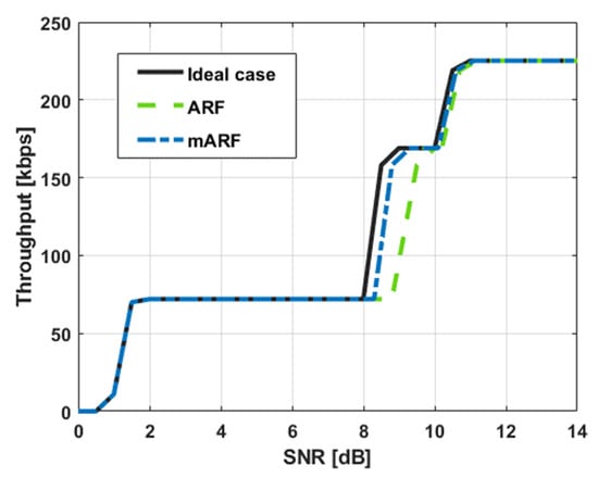
Figure 6.
Comparison of throughput in three-ray channel model.
We also optimized the performance of mARF by dynamically adjusting the threshold instead of using a fixed MCS profile change threshold. To achieve this, simulations were conducted to assess the performance of mARF by incrementally increasing the α value, which determines the MCS-changing counter, from 0 to 1 in intervals of 0.1. The simulation results, as depicted in Figure 7, confirmed that the optimal performance was achieved when α had a value of 0.7. As a result, the default value for α was set to 0.7.
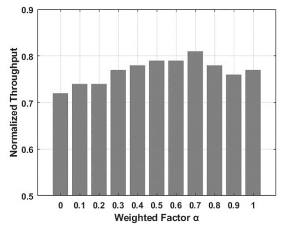
Figure 7.
Comparison of normalized throughput as a weighted factor.
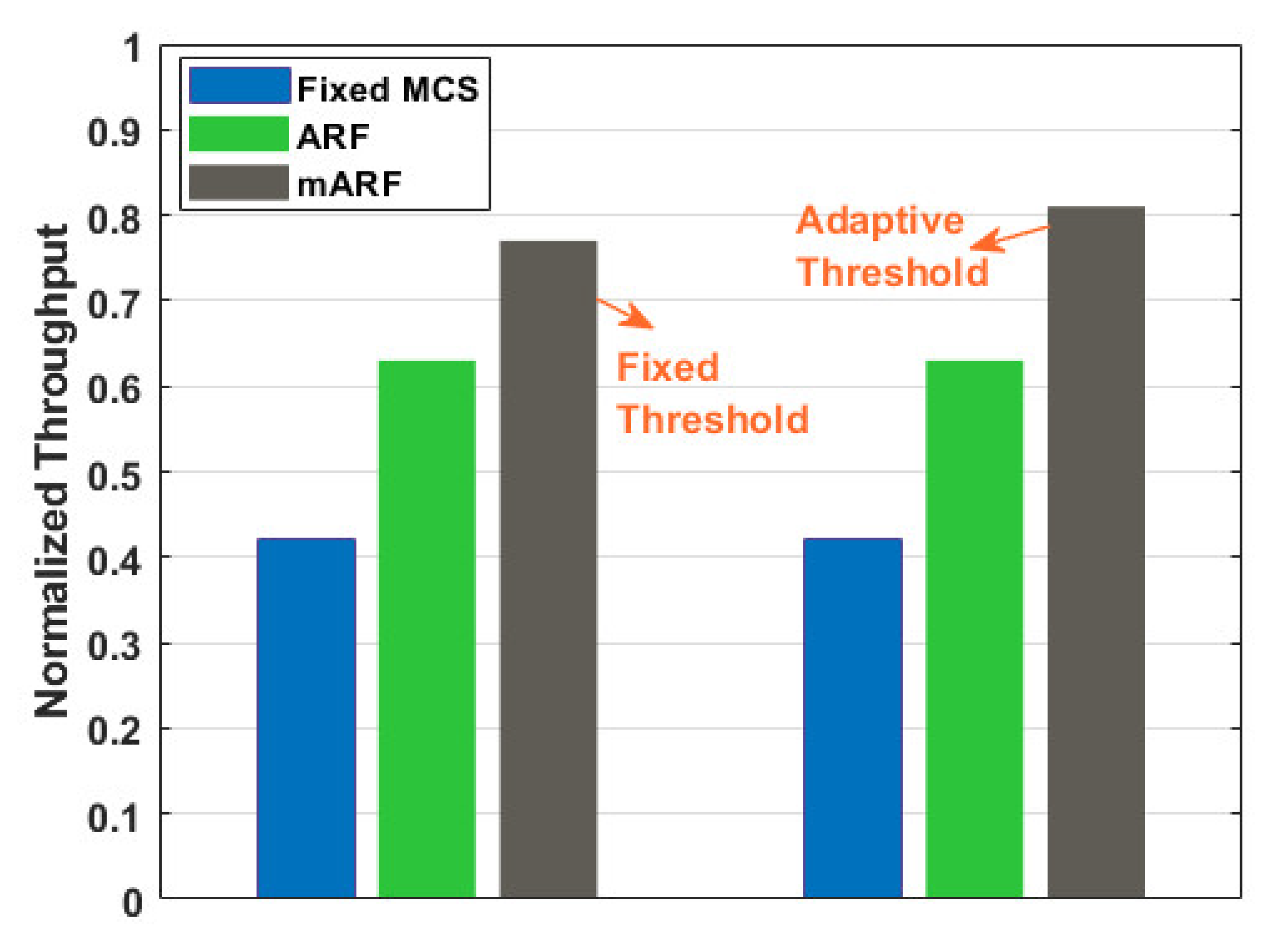
Finally, we simulated the average throughput of the fixed MCS case, traditional ARF techniques, and mARF, as shown in Figure 8. We confirmed that, on average, the mARF technique improves the performance by 14% compared to the traditional ARF technique because the mARF technique can respond appropriately to the maritime environment. In addition, we proved that the mARF technique can enhance VDE-TER performance: when the mARF technique is applied with an adaptive threshold. The mARF technique with an adaptive threshold can increase the throughput by 18% compared with the traditional ARF technique.
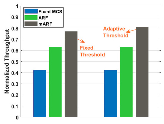
Figure 8.
Normalized throughput comparison between mARF and existing technique.
5. Conclusions
Communication technology in the maritime domain has seen slower evolution than terrestrial communication. However, the advent of various marine applications has triggered a growing need for communication that can ensure stability and high transmission rates in marine environments. In this paper, we introduce the mARF technique, which is designed to enhance transmission rates while maintaining reliable communication by effectively addressing the challenges of the marine communication environment. The mARF technique handles the deep null phenomenon, which is a prevalent problem in marine communication, through the implementation of fast drop-out and fast recovery mechanisms. Furthermore, we demonstrate that the threshold for a fast recovery operation can be dynamically updated by leveraging existing communication success records. Through simulations, we provide empirical evidence of the ability of this technique to efficiently regulate transmission rates to meet the demands of marine communication environments. However, mARF has a limitation whereby the communication history is not updated when the VDES enters sleep status and does not transmit data. mARF operates based on previous communication history, which is not representative of the current channel state in VDES sleep status. To address these limitations, the mARF technique can be combined with intelligent algorithms in the future. The proposed mARF technology is not only implementable and operational within a real VDES, but also possesses the potential for expansion into an intelligent algorithm. This algorithm can collaborate with the VDES internal scheduler to control the transmission cycles by considering data transmission delays, thereby further enhancing its adaptability to real-world maritime communication scenarios. Additionally, innovative technologies such as stacked intelligent metasurface (SIM)-aided communications will also be applied to maritime communications in the future. When technologies such as SIM are applied in the future, research on channel capacity optimization in the maritime environment is essential and needs to be conducted.
Author Contributions
W.S. devised the basic concept of the proposed scheme; B.K. performed implementation of the simulation code; E.-J.K. validated the results; D.K. supervised the whole procedure related to this paper. All authors have read and agreed to the published version of the manuscript.
Funding
This research was supported by a grant from the Republic of Korea National R&D Project, “Development of VDES for shipborne mobile station with satellite and base station with net-work management”, funded by the Ministry of Oceans and Fisheries (RS-2023-00256110).
Data Availability Statement
Data are contained within the article.
Conflicts of Interest
The authors declare no conflicts of interest.
References
- Wei, T.; Feng, W.; Chen, Y.; Wang, C.X.; Ge, N.; Lu, J. Hybrid satellite-terrestrial communication networks for the maritime Internet of Things: Key technologies, opportunities, and challenges. IEEE Internet Things J. 2021, 8, 8910–8934. [Google Scholar] [CrossRef]
- Zolich, A.; Palma, D.; Kansanen, K.; Fjørtoft, K.; Sousa, J.; Johansson, K.H.; Johansen, T.A. Survey on communication and networks for autonomous marine systems. J. Intell. Robot. Syst. 2019, 95, 789–813. [Google Scholar] [CrossRef]
- Aslam, S.; Michaelides, M.P.; Herodotou, H. Internet of ships: A survey on architectures, emerging applications, and challenges. IEEE Internet Things J. 2020, 7, 9714–9727. [Google Scholar] [CrossRef]
- ITU-R. Automatic Identification System VHF Data Link Loading; ITU-R M. 2287-0; ITU: Geneva, Switzerland, 2014. [Google Scholar]
- Anwar, S.M.; Goron, E.; Toutain, Y.; Péronne, J.P.; Héthuin, S. LTE terminal for maritime applications. In Proceedings of the 2013 Military Communications and Information Systems Conference, Saint-Malo, France, 7–9 October 2013; IEEE: Piscataway, NJ, USA, 2013; pp. 1–4. [Google Scholar]
- Xu, Y. Quality of service provisions for maritime communications based on cellular networks. IEEE Access 2017, 5, 23881–23890. [Google Scholar] [CrossRef]
- Lopes, M.J.; Teixeira, F.; Mamede, J.B.; Campos, R. Wi-Fi broadband maritime communications using 5.8 GHz band. In Proceedings of the 2014 Underwater Communications and Networking (UComms), Sestri Levante, Italy, 3–5 September 2014; IEEE: Piscataway, NJ, USA, 2014; pp. 1–5. [Google Scholar] [CrossRef]
- Campos, R.; Oliveira, T.; Cruz, N.; Matos, A.; Almeida, J.M. BLUECOM+: Cost-effective broadband communications at remote ocean areas. In Proceedings of the OCEANS 2016-Shanghai, Shanghai, China, 10–13 April 2016; IEEE: Piscataway, NJ, USA, 2016; pp. 1–6. [Google Scholar] [CrossRef]
- Teixeira, F.B.; Oliveira, T.; Lopes, M.; Ruela, J.; Campos, R.; Ricardo, M. Tethered balloons and TV white spaces: A solution for real-time marine data transfer at remote ocean areas. In Proceedings of the 2016 IEEE Third Underwater Communications and Networking Conference (UComms), Lerici, Italy, 30 August–1 September 2016; IEEE: Piscataway, NJ, USA, 2016; pp. 1–5. [Google Scholar] [CrossRef]
- International Telecommunication Union. Technical Characteristic for a VHF Data Exchange System in the VHF Maritime Mobile Band; Recommendation ITU-R M.2092-0+; ITU: Geneva, Switzerland, 2015. [Google Scholar]
- Molina, N.; Cabrera, F.; Araña, V.; Tichavska, M. An overview about the physical layer of the vhf data exchange system (vdes). In Computer Aided Systems Theory—EUROCAST 2019; EUROCAST 2019; Lecture Notes in Computer Science; Moreno-Díaz, R., Pichler, F., Quesada-Arencibia, A., Eds.; Springer: Cham, Switzerland, 2019. [Google Scholar]
- Lázaro, F.; Raulefs, R.; Wang, W.; Clazzer, F.; Plass, S. VHF Data Exchange System (VDES): An enabling technology for maritime communications. CEAS Space J. 2019, 11, 55–63. [Google Scholar] [CrossRef]
- Cao, Y.; Ohtsuki, T.; Maghsudi, S.; Quek, T.Q. Deep Learning and Image Super-Resolution-Guided Beam and Power Allocation for mmWave Networks. IEEE Trans. Veh. Technol. 2023, 72, 15080–15085. [Google Scholar] [CrossRef]
- Echigo, H.; Cao, Y.; Bouazizi, M.; Ohtsuki, T. A deep learning-based low overhead beam selection in mmWave communications. IEEE Trans. Veh. Technol. 2021, 70, 682–691. [Google Scholar] [CrossRef]
- Rinaldo, R.; Gaudenzi, R.D. Capacity Analysis and System Optimization for the Forward Link of Multi-Beam Satellite Broadband Systems Exploiting Adaptive Coding and Modulation. Int. J. Satell. Commun. Netw. 2004, 22, 401–423. [Google Scholar] [CrossRef]
- Rinaldo, R.; Gaudenzi, R.D. Capacity Analysis and System Optimization for the Reverse Link of Multi-Beam Satellite Broadband Systems Exploiting Adaptive Coding and Modulation. Int. J. Satell. Commun. Netw. 2004, 22, 425–448. [Google Scholar] [CrossRef]
- Cioni, S.; De Gaudenzi, R.; Rinaldo, R. Channel Estimation and Physical Layer Adaptation Techniques for Satellite Networks Exploiting Adaptive Coding and Modulation. Int. J. Satell. Commun. Netw. 2008, 26, 157–188. [Google Scholar] [CrossRef]
- Xu, C.; Xiang, L.; An, J.; Dong, C.; Sugiura, S.; Maunder, R.G.; Yang, L.L.; Hanzo, L. OTFS-aided RIS-assisted SAGIN systems outperform their OFDM counterparts in doubly selective high-Doppler scenarios. IEEE Internet Things J. 2022, 10, 682–703. [Google Scholar] [CrossRef]
- IALA Guideline G1117: VHF Data Exchange System (VDES) Overview Edition 3.0. Available online: https://www.iala-aism.org/product/g1117/ (accessed on 1 December 2023).
- MSC. 1/Circ.1595—E-Navigation Strategy Implementation Plan—Update 1; IMO: London, UK, 2018. [Google Scholar]
- Lee, Y.H.; Meng, Y.S. Key considerations in the modeling of tropical maritime microwave attenuations. Int. J. Antennas Propag. 2015, 2015, 246793. [Google Scholar] [CrossRef]
- Maliatsos, K.; Loulis, P.; Chronopoulos, M.; Constantinou, P.; Dallas, P.; Ikonomou, M. Measurements and wideband channel characterization for over-the-sea propagation. In Proceedings of the 2006 IEEE International Conference on Wireless and Mobile Computing, Networking and Communications, Montreal, QC, Canada, 19–21 June 2006; IEEE: Piscataway, NJ, USA, 2006; pp. 237–244. [Google Scholar] [CrossRef]
- Timmins, I.; O’Young, S. Marine Communications Channel Modeling Using the Finite-Difference Time Domain Method. IEEE Transaction. Veh. Technol. 2008, 58, 2626–2637. [Google Scholar] [CrossRef]
- Yang, K.; Roste, T.; Ekman, T. Experimental multipath delay profile of mobile radio channels over sea at 2 GHz. In Proceedings of the 2012 Loughborough Antennas and Propagations Conference, Loughborough, UK, 12–13 November 2012; pp. 1–4. [Google Scholar] [CrossRef]
- Zaidi, K.S.; Jeoti, V.; Drieberg, M.; Awang, A.; Iqbal, A. Fading characteristics in evaporation duct: Fade margin for a wireless link in the South China Sea. IEEE Access 2018, 6, 11038–11045. [Google Scholar] [CrossRef]
- Wang, J.; Zhou, H.; Li, Y.; Sun, Q.; Wu, Y.; Jin, S.; Quek, T.Q.; Xu, C. Wireless channel models for maritime communications. IEEE Access 2018, 6, 68070–68088. [Google Scholar] [CrossRef]
- Meng, Y.S.; Lee, Y.H. Measurements and characterizations of air-to-ground channel over sea surface at C-band with low airborne altitudes. IEEE Trans. Veh. Technol. 2011, 60, 1943–1948. [Google Scholar] [CrossRef]
- Holland, G.; Vaidya, N.; Bahl, P. A rate-adaptive MAC protocol for multi-hop wireless networks. In Proceedings of the 7th Annual International Conference on Mobile Computing and Networking, Association for Computing Machinery, New York, NY, USA, 16 July 2001; pp. 236–251. [Google Scholar] [CrossRef]
- Kamerman, A.; Monteban, L. WaveLAN®-II: A high-performance wireless LAN for the unlicensed band. Bell Labs Tech. J. 1997, 2, 118–133. [Google Scholar] [CrossRef]
- Tse, D.; Viswanath, P. Fundamentals of Wireless Communication; Cambridge University Press: Cambridge, UK, 2005. [Google Scholar] [CrossRef]
- Goldsmith, A. Wireless Communications; Cambridge University Press: Cambridge, UK, 2005. [Google Scholar] [CrossRef]
Disclaimer/Publisher’s Note: The statements, opinions and data contained in all publications are solely those of the individual author(s) and contributor(s) and not of MDPI and/or the editor(s). MDPI and/or the editor(s) disclaim responsibility for any injury to people or property resulting from any ideas, methods, instructions or products referred to in the content. |
© 2024 by the authors. Licensee MDPI, Basel, Switzerland. This article is an open access article distributed under the terms and conditions of the Creative Commons Attribution (CC BY) license (https://creativecommons.org/licenses/by/4.0/).

