Abstract
To solve the problem of the oscillation stability of direct-driven wind-powered grid-connected systems with a low-voltage crossing control, a method of oscillation stability analysis for these systems, based on interactive energy, is proposed in this paper. Firstly, a dynamic energy model of a direct-driven wind-powered grid-connected system is established, considering a low-voltage traverse control. Secondly, the energy is divided into four parts—the line parameter energy, current inner loop energy, PLL energy, and current inner loop–PLL interaction energy—and the conduction path of the energy during a low-voltage crossing is described. On this basis, the aperiodic components of each energy path are analyzed, the stability level of the system is quantified, the influence of the different control parameters on the interactive energy dissipation is deduced, the key interactive control links affecting the stability of the system are screened, and the influence rules of the parameters are expounded. Finally, a direct-driven wind-powered grid-connected system model is built on the Rt-lab platform, and it is verified by a simulation test. The results show that the interaction energy generated by the interaction of the current inner loop and phase-locked loop is a key factor affecting the stability of the direct-driven wind-powered grid-connected system. The simulation test parameters of the control group were adjusted as the current inner loop’s proportion parameter increased from 1.32 to 5.28, the current inner loop’s integral parameter increased from 4.48 to 6.42, the PLL’s proportion parameter decreased from 9.45 to 6.3, and the PLL’s integral parameter decreased from 50.25 to 40.2. Both the theoretical and experimental results show that increasing the current inner loop’s integral and proportion parameters can improve the stability level of the direct-driven wind-powered grid-connected system; reducing the phase-locked loop’s proportion and integral parameters can also improve the stability level of the grid-connected system.
1. Introduction
In recent years, with the high proportion of wind power connected to the power grid, the problem of broadband oscillation stability caused by the interaction of the multiple control links of power electronic converters has become prominent. In particular, when the control strategy of wind turbines is switched, it is easy to introduce a new interactive path of control links, change the damping characteristics of the system, cause system oscillation divergence, and threaten the safe and stable operation of the power system. Therefore, it is of great significance to study the oscillation instability mechanism of grid-connected wind power systems after switching control strategies and its key influencing factors for rapidly blocking system oscillation and ensuring power grid security. This paper mainly takes the low-voltage control scenario of direct-driven wind turbines during the fault period as an example to explore the key factors affecting the oscillation stability of the system after the switch of the control strategy and provides an oscillation suppression scheme for parameter adjustment.
At present, impedance analysis, eigenvalue analysis, and the energy function method are used to analyze the oscillation stability of wind power grid-connected systems. The impedance analysis method mainly constructs the impedance model of the grid-connected system and analyzes the system stability by using the Nyquist criterion. In the literature, some authors [1,2] have established an impedance network of direct-driven wind-powered grid-connected systems, analyzed the key nodes and branches that affect the stability of the system, and considered the idea that heavy-duty transmission lines are the key factors affecting the oscillation. In view of the scenario of direct-driven wind power connected to a weak power grid, refs. [3,4] analyzed the influence of a grid-side converter on the stability of the grid-connected system of direct-drive fans and believed that the control parameters of the grid-side converter have an important impact on the stability of the grid-connected system. The eigenvalue analysis method mainly establishes the state–space model of the grid-connected system and judges the stability of the system according to the eigenequation and the latent root. The authors of [5,6] focused on analyzing the influence of the PLL parameters on the stability of grid-connected systems in scenarios where direct-driven wind power is connected to weak power grids with heavy loads. It is believed that the PLL parameters are not conducive to direct-drive grid-connected systems with heavy loads in weak power grids, and the weaker the connections between the power grids and the more loads, the more obvious the PLL effect. On the basis of the above studies, the authors of [7,8] considered the influence of control delay and virtual control, respectively, on the stability of a wind power grid-connected system; they believed that there was a cross effect between the phase-locked loop and the current inner loop and they put forward the idea of reasonably adjusting the controller parameters to improve the stability of the grid-connected system. The energy function method mainly establishes the energy model of the grid-connected system and analyzes the stability of the grid-connected system by using the Lyapunov direct method theory. The authors of [9] analyzed the influence of virtual synchronous control on the stability of a wind power grid-connected system from the perspective of interactive energy, considered that the virtual synchronous control link and the coupling link between the virtual synchronous control and active power control were the main factors affecting the stability of the grid-connected system, and proposed the additional energy branch oscillation suppression strategy. On the basis of the above studies, the authors of [10,11] further studied the influence of power coupling on the stability of the system, considered that power coupling could be used as the transmission path of the oscillation energy, and proposed a nonlinear elastic coupling control strategy. Although the impedance analysis method can directly obtain the corresponding system impedance values at different frequencies, it mainly focuses on the complex impedance characteristics of the system, often ignores the time-domain behavior and dynamic process of the system, and cannot accurately indicate the stability level of the system in the time domain. The key to eigenvalue analysis is to solve the eigenvalue of the state–space equation, which is often difficult to solve for a nonlinear time-varying system. Compared with the above two methods of oscillation stability analysis, the energy function method has strong adaptability to nonlinear links and can reveal the interaction mechanism of all the links [12], which can be widely used in online real-time computing scenarios. Based on the above research methods, the existing research mainly focuses on an analysis of the oscillation stability of a wind power-connected AC system under the steady-state scenario, without considering the influence of control strategy switching and control links on the stability of the wind power grid-connected system during the fault period.
This article is structured as follows. Section 2 establishes the dynamic energy model of a grid-connected direct-driven wind power system with low-voltage crossing control. The energy is separated into four categories: line energy, phase-locked loop energy, current inner loop energy, and current inner loop–phase-locked loop interaction energy. Section 3 examines the aperiodic components of each energy path, quantifies the grid-connected system’s stability level, identifies the main control links that have an impact on the system’s stability, reveals the influence law of the control links on the system’s stability, and suggests an oscillation suppression scheme for parameter modification. Section 4 builds a grid-connected, direct-driven wind power system model using the MATLAB R2021b/Simulink 64 bit simulation platform to confirm that the theoretical analysis is accurate. Finally, Section 5 concludes this article. We exhibit the structure of this research as a graph, as seen in Figure 1, for demonstration.
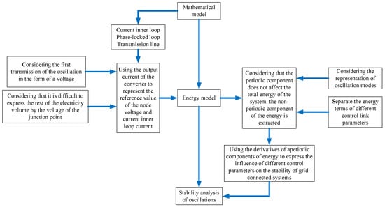
Figure 1.
Flowchart of study on the oscillation stability of direct-driven wind-powered grid-connected system.
2. Dynamic Energy Model of Direct-Driven Wind-Powered Grid-Connected System during Low-Voltage Crossing
There are many inducing factors for direct-driven wind turbines with LVRT. In this paper, the most common three-phase short-circuit fault through transition resistance is taken as an example to analyze. The control framework of a typical grid-connected direct-drive wind power system is depicted in Figure 2.
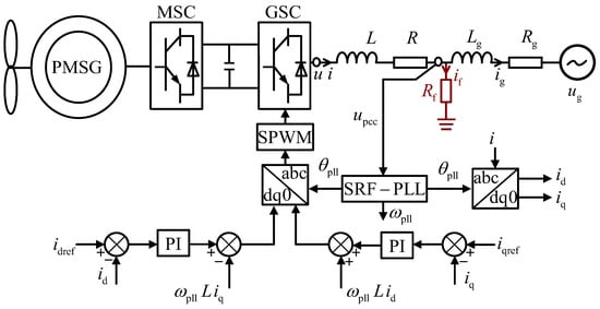
Figure 2.
Structure diagram of a grid-connected system of direct-drive wind power during LVRT.
In Figure 2, and are the line impedance from the converter port of the direct-driven wind turbine to the junction point. and are the line impedance from the junction point to the power grid. The short-circuit fault of the three-phase transition resistance occurs at the junction point, and the transition resistance is and the short-circuit current is . and are the output angular frequency and phase angle of the PLL, respectively; and are the feedforward compensation terms of the current inner loop. , , , , and represent the converter port voltage, output current, junction voltage, grid-connected current, and grid voltage of direct-driven wind turbines, respectively. Subscript d and q correspond to the electrical volume in the rotating coordinate system of d-q, and subscript “ref” is the command value of the corresponding electrical volume.
2.1. Mathematical Model of Direct-Drive Wind-Powered Grid-Connected System during Low-Voltage Crossing
A direct-drive wind turbine’s control link primarily consists of a current inner loop and a phase-locked loop. The three-phase synchronous PLL’s mathematical model is represented by the following expression:
where and are the proportional coefficient and integral coefficient of the phase-locked loop PI controller, respectively, and is the synchronous angular velocity.
The mathematical model of the current inner loop can be expressed as:
where and are the proportions and integral coefficients under the control of PI of the inner loop of the current, respectively.
The current inner loop command value is stated as follows when the direct-driven wind-powered grid-connected system is operating steadily:
where and are the proportional coefficient and integral coefficient of the voltage outer ring, respectively, and and are the command values of the DC voltage and the actual value of DC voltage, respectively.
When the junction voltage drops to 0.2 times the rated voltage, the low-voltage crossing control is put in, and the command value of the current inner loop changes from the command value of stable operation to:
where is the reactive current support coefficient, is the rated voltage of the junction point, and is the rated current of the grid-side converter.
According to Kirchhoff’s current law, the KCL equation at the junction point is derived, and the expression after Park transformation is as follows:
Similarly, the relation expression of junction voltage, transition resistance, and short circuit current is as follows:
By connecting Equations (5) and (6), the expression between the grid-connected current and the output current of the direct-drive fan is derived as follows:
where represents the time, is the time when the fault occurs, and the expressions of coefficients is . Below are the expressions for and .
Similarly, the expression between the junction voltage and the output current of direct-driven wind turbines is derived as follows:
According to Equation (6), the d-axis component of the output current of the direct-drive wind turbine can be expressed as follows:
Equations (7) and (9) can be substituted into Equations (10) to obtain:
where “” represents the variation of the corresponding electrical quantity, and subscript “0” represents the steady-state quantity of the corresponding electrical quantity before failure. The expression of the coefficient is as follows:
The inverse solution (11) gives:
The expression of the d- and q-axis components of the voltage at the junction point is obtained by linearizing Equation (7), as follows:
where the expressions of and are as follows:
Equation (9) is linearized and substituted into Equation (4) to derive the expression of the command value of the current inner loop as follows:
where the expressions of , , , and are as follows:
2.2. Dynamic Energy Model of Direct-Drive Fan during Low-Voltage Crossing
The authors of [13] proposed a dynamic energy modeling method based on the current equation of bus nodes. The energy function of the direct-driven wind-powered grid-connected system shown in Figure 2 can be expressed as:
where is the system admittance matrix, is the bus voltage column vector, and is the column vectors of injected current at the generator node and load node, respectively. Take the generator part of the system energy, expand it in the time domain, and express the electrical volume as the instantaneous value to obtain the dynamic energy of the port of the direct-driven wind turbine in the coordinate system :
Each control link of the direct-drive wind turbine is based on the time domain rotating coordinate system. By replacing the voltage and current in Equation (19) with the time domain component in the rotating coordinate system, the energy function in the time domain can be obtained as follows:
Equations (1) and (2) are substituted into Equation (20) to obtain the dynamic energy model of the direct-driven wind turbine during the low-voltage crossing:
To facilitate the analysis of the influence of control parameters and system stability level, the instantaneous quantity of voltage and current in Equation (21) is expressed as the sum of steady-state quantity and variable quantity, that is, ; it is speculated that, when the low-voltage traverse control is applied at time , the expression for the total energy variation of direct-driven wind turbines is as follows:
It can be seen from Equation (22) that energy is related to the change of voltage and current. To further analyze the energy expression, Equations (13), (14) and (16) are substituted into Equation (22), and it is considered that the value accumulated at the moment of axial junction voltage is equal to , while the voltage at the moment of the junction point changes instantaneously. Therefore, is used as a substitute to represent the instantaneous change of the voltage of the axis junction point, and the rest of the sudden change of electricity consumption is also replaced; the expression of the change of the total energy of the final direct-driven wind turbine is as follows:
where is the line parameter energy, is the current inner loop energy, is the phase-locked loop energy, and is the current inner loop–phase-locked loop interaction energy. See Appendix A for specific expressions.
3. Analysis of System Stability after Low-Voltage Traverse Control Switching
3.1. Dynamic Energy Stability Analysis Criterion
Lyapunov stability theory points out that, for a dynamic system, if the total energy of the system is (, where is the system state quantity), and the change rate with time is always negative, then the total energy of the system continues to decrease, which can indicate that the system is stable, and vice versa.
When the system oscillates, the change of voltage and current is considered as the oscillation [14], which is expressed as:
where and are, respectively, the oscillation amplitude of the junction point d and the q-axis; and are, respectively, the initial phase Angle of the junction point d and the q-axis oscillation; and are, respectively, the oscillation amplitude of the wind field current d and the q-axis oscillation; and are, respectively, the initial phase angle of the wind field current d and the q-axis oscillation. indicates the oscillation attenuation coefficient.
By substituting the oscillation quantity expression into Equation (23), the total energy expression of direct-driven wind turbines contains periodic energy terms and non-periodic energy terms. In a period, the periodic energy term has almost no effect on the increase or decrease in the total energy, which can be ignored [15]. The impact of the aperiodic energy term on the stability level of the grid-connected direct-driven wind power system is described by its derivative term. The expression is as follows:
where is the aperiodic derivative term of the energy of the inner loop of the current, is the aperiodic derivative term of the energy of the phase-locked loop, and is the aperiodic derivative term of the interaction energy of the inner loop of the current and the phase-locked loop. is used to represent the aperiodic derivative term of each energy. According to Lyapunov stability theory, if is used, it means that the corresponding energy has a positive damping effect on the stability of the grid-connected system, which is conducive to the system maintaining stability. The larger is, the faster the oscillation convergence will be, and the more stable system will be. indicates that the corresponding energy has a negative damping effect on the stability of the grid-connected system and aggravates the system instability. The greater the value of , the faster the oscillation divergence and the higher the risk of system instability.
3.2. Influence of Energy Interaction Path on the Stability of Direct-Driven Wind Power Grid-Connected System
3.2.1. The Influence of Current Inner Loop Energy on the Oscillation Stability of the System
The expression of the aperiodic derivative term of the inner loop energy of the current is as follows:
Extract the energy term corresponding to the parameters in Equation (26):
According to Formula (12), , since the direct-drive fan as a whole is perceptual, . As shown in Equation (27), the influence of the parameter on the total energy of the direct-drive wind field depends on the positive and negative properties of and . According to the amplitude–phase characteristic analysis method, there are and in the wide-frequency state range. See Appendix B for detailed derivation. According to the above analysis, it can be seen that ; according to the dynamic energy stability criterion, the increase in the current inner loop ratio parameter can reduce the instability risk of the grid-connected system, and is conducive to the stability of the direct-driven wind-powered grid-connected system. The influence of the parameter on the stability of grid-connected systems can also be analyzed. To sum up, increasing the proportional parameters and integral parameters of the current inner loop is conducive to the stability of the direct-driven wind-powered grid-connected system.
3.2.2. The Influence of PLL Energy on the Oscillation Stability of the System
The expression of the aperiodic derivative term of the PLL energy is:
We extract the energy term corresponding to the parameter in Equation (28):
As shown in Equation (29), the influence of the parameter on the total energy of direct-driven wind turbines depends on the positive and negative properties . Using the amplitude–phase characteristic analysis method, it can be seen that, in the wide-frequency state range, there is , which is derived in Appendix B in detail. According to the above analysis, it can be seen that ; according to the dynamic energy stability criterion, the increase in the PLL ratio parameter will increase the instability risk of the grid-connected system, which is not conducive to the stability of the grid-connected system of the direct-drive wind field. The influence of the parameter on the stability of grid-connected systems can also be analyzed. To sum up, increasing the proportional parameters and integral parameters of PLL will aggravate the instability risk of the direct-driven wind-powered grid-connected system.
3.2.3. The Influence of the Current Inner Loop and Phase-Locked Loop Interaction Energy on the Oscillation Stability of the System
The expression of the aperiodic derivative term of the current inner loop–PLL interaction energy is as follows:
We extract the energy term corresponding to the parameter in Equation (30):
According to Equation (31), the influence of parameters on the total energy of direct-driven wind turbines is jointly determined by the positive and negative properties of the three parts , , and . Since there is a coefficient in , is very small at steady state, and and are derived. So, the positive and negative properties are mainly determined by . The positivity of depends on the positivity of and , and since is very close to 0, only the positivity of is analyzed. By the method of amplitude–phase characteristic analysis, it can be seen that, in the range of wide-frequency states, there are , which are derived in detail in Appendix B. According to the above analysis, it can be seen that , according to the dynamic energy stability criterion, the increase in the coupling parameters of the current inner loop ratio parameter and the phase-locked loop ratio parameter will increase the instability risk of the grid-connected system, which is not conducive to the stability of the grid-connected system of the direct-drive wind field. The influence of parameters , , and on the stability of grid-connected system can also be analyzed. The instability risk of a direct-driven wind-powered grid-connected system will be exacerbated by increasing the current inner loop proportion–PLL ratio parameter and the current inner loop integral–PLL integral parameter; conversely, the instability risk will be decreased by increasing the current inner loop integral–PLL ratio parameter and the current inner loop integral–PLL integral parameter. Combined with the aperiodic energy term of each energy, the aperiodic energy term of the current inner loop–PLL interaction energy contains 4 multiplicative terms of the amplitude of electric gas oscillation, and the aperiodic energy term of the current inner loop energy and the aperiodic energy term of the PLL energy contain 2 multiplicative terms of electric gas oscillation amplitude; , are derived. Therefore, the increase and decrease trend of the total energy of the direct-driven wind-powered grid-connected system is mainly determined by .
4. Simulation Analysis
4.1. Test System
To verify the correctness of the dynamic energy model of direct-driven wind turbines during the low-voltage crossing period mentioned in this paper, a direct-driven wind-powered grid-connected system, as shown in Figure 2, was built on the Rt-lab simulation platform. Under different working conditions of the system, the accuracy of the dynamic energy model was first verified. Secondly, the actual simulation diagram of real-time simulation analysis is used to verify the correctness of the analysis conclusion. The simulation scenario is as follows: when the connecting point of the direct-driven wind-powered grid-connected system is at , the three-phase ground fault occurs through the transition resistance , and then the low-voltage crossing control is put in.
4.2. Dynamic Energy Model Verification of Direct-Driven Wind-Powered Grid-Connected System
Simulation examples under two working conditions of oscillation convergence and oscillation divergence are set, and the control parameter values are shown in Table 1.

Table 1.
Values of control parameters under different working conditions.
During the LVRT, the change trajectories of the junction voltage, the output current of the direct-driven wind turbine, and the total energy variation of the direct-driven wind turbine under two conditions of oscillation convergence and oscillation divergence are shown in Figure 3, Figure 4 and Figure 5.

Figure 3.
The voltage curve of the junction points under conditions of oscillation convergence. (a) Voltage of junction point under oscillatory convergence condition; (b) voltage of junction point under oscillating divergence condition.

Figure 4.
The output current of PMSG under different working conditions. (a) The output current of PMSG under oscillation convergence condition; (b) the output current of PMSG under oscillating divergence condition.

Figure 5.
Change trajectory under different working conditions. (a) The changing trajectory under the condition of oscillation convergence; (b) the changing trajectory under the oscillatory divergence condition.
Firstly, the correctness of the dynamic energy model under the condition of oscillation convergence is verified. As shown in Figure 3a and Figure 4a, after the low-voltage crossing control is put into operation, the voltage of the parallel node and the output current of the direct-drive wind turbine initially fluctuate greatly, and then oscillate and converge. It can be seen from Figure 5a that the trajectory of total energy variation of direct-driven wind turbines decreases rapidly under the condition of oscillation convergence. Therefore, the dynamic energy model can reflect the stability level of grid-connected systems under the condition of oscillation convergence. Similarly, as shown in Figure 3b and Figure 4b, the junction voltage and output current of the direct-driven wind turbine generator oscillate and diverge after low-voltage crossing control is applied. Combined with Figure 5b, it can be seen that the energy of the direct-driven wind turbine generator gradually increases under the condition of diverging oscillation, so the dynamic energy model can reflect the stability level of the grid-connected system under the condition of diverging oscillation. In summary, the dynamic energy model of the direct-drive wind turbine is correct and can reflect the stability level of the grid-connected system.
4.3. Energy Path Verification of Direct-Driven Wind-Powered Grid-Connected System
The energy derivatives and changing trends of aperiodic energies of the current inner loop, phase-locked loop, and current inner loop–phase-locked loop interaction are shown in Figure 6 and Figure 7.
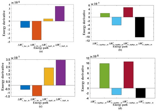
Figure 6.
The derivative of the energy of , , and under different working conditions. (a) The energy derivatives of , , , and under oscillatory convergence conditions; (b) the energy derivatives of , , , and under the oscillatory divergence condition; (c) the energy derivatives of , , , and under oscillatory convergence conditions; (d) the energy derivative of , , , and under the oscillatory divergence condition.
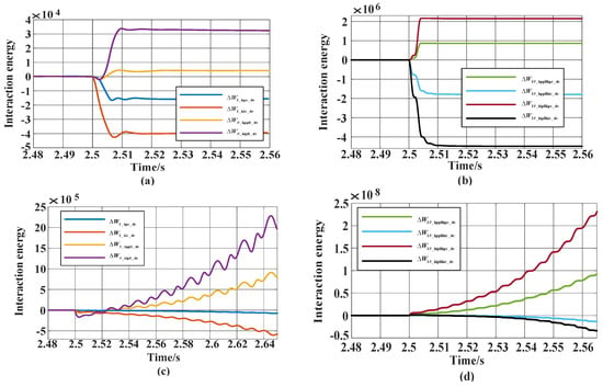
Figure 7.
Change trajectories of , , and under different working conditions. (a) Trajectories of , , , and under oscillatory convergence condition; (b) trajectories of , , , and under the oscillatory convergence condition; (c) the trajectories of , , , and under the oscillatory divergence condition; (d) the trajectories of , , , and under the oscillatory divergence condition.
As shown in Figure 6 and Figure 7, the non-periodic energies in the inner current loops of and show a decreasing trend, regardless of the oscillatory convergence condition or the oscillatory divergence condition, which helps to reduce the total energy of direct-driven wind turbines and is conducive to the stability of the grid connection system. The non-periodic energies of PLL energies and show increasing trends, helping to increase the total energy of direct-driven wind turbines, which is not conducive to the stability of grid-connected systems. The current inner loop–phase-locked loop interaction aperiodic energies and show a decreasing trend, helping to reduce the total energy of direct-driven wind turbines, conducive to the stability of the grid-connected system; and show an increasing trend, helping to increase the total energy of direct-driven wind turbines is not conducive to the stability of the grid-connected system. By comparing Figure 6a with Figure 6c, we can see that the aperiodic energy derivatives of the current inner loop and PLL under the oscillating divergence condition are larger than those under the oscillating convergence condition. Similarly, the aperiodic energy derivatives of the current inner loop and PLL interaction are also found by comparing Figure 6b with Figure 6d. Therefore, the absolute value of the energy derivative can be used to characterize the influence of the energy interaction path on the stability of the grid-connected system. By further comparing Figure 6c with Figure 6d, it can be seen that , ; therefore, it can be determined that the key factor affecting the stability of the grid-connected system is the interaction energy of the current inner loop and phase-locked loop, and the interaction link of the current inner loop and phase-locked loop is the key link affecting the stability of the grid-connected system. In summary, the simulation analysis is consistent with the above analysis of the influence of the stability of the direct-driven wind-powered grid-connected system, which verifies the effectiveness of the stability analysis method proposed in this paper.
4.4. Control Parameter Influence Analysis Validation
As indicated in Table 2, several combinations of control parameters are specified. Figure 8 displays the variation trend of the direct-drive wind turbine output current and the junction voltage under various combinations.

Table 2.
Values for different combinations of control parameters.
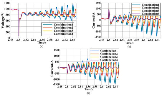
Figure 8.
Variation trajectories of electrical volume under different combinations. (a) The voltage of junction points under different combinations; (b) d-axis component of PMSG output current under different combinations; (c) q-axis component of PMSG output current under different combinations.
As shown in Figure 8, these four combinations cover the range from the divergence to the convergence of the oscillations. By comparing the change trajectory of combination 1 and combination 2 in Figure 8, it can be seen that increasing the current loop integral parameter from 4.84 to 6.42 is conducive to the oscillation stability of the direct-driven wind-powered grid-connected system. Comparing combination 2 and combination 3, it can be seen that the oscillation stability of the grid-connected system is improved by reducing the proportion parameter from 9.45 to 6.3 and the integral parameter from 50.25 to 40.2 in the PLL control parameters. Comparing combination 3 and combination 4, it can be seen that increasing the current loop ratio parameter from 1.32 to 5.25 is conducive to the oscillation stability of the grid-connected system, which is consistent with the above stability analysis conclusion.
5. Conclusions
Aiming to resolve the oscillation stability problem of direct-driven wind-powered grid-connected systems during LVRT, an energy function method is proposed to analyze the oscillation stability of direct-driven wind-powered grid-connected systems based on interactive energy. The main conclusions are as follows:
- The dynamic energy model of a direct-driven wind-powered grid-connected system with low-voltage crossing control is derived. The energy includes line parameter energy, current inner loop energy, phase-locked loop energy, and current inner loop–phase-locked loop interaction energy.
- The primary element influencing a direct-driven wind-powered grid-connected system’s stability level is the current inner loop–PLL interaction. The direct-driven wind-powered grid-connected systems are more stable when there is a current inner loop integration–PLL interaction and a current inner loop integration–PLL proportional interaction. The grid-connected systems’ stability is not supported by the existing inner loop proportional–PLL integral interaction or inner loop proportional–PLL proportional interaction.
- The simulation test parameters of the control group were adjusted as follows: the current inner loop proportion parameter increased from 1.32 to 5.28, the current inner loop integral parameter increased from 4.48 to 6.42, the PLL proportion parameter decreased from 9.45 to 6.3, and the PLL integral parameter decreased from 50.25 to 40.2. Both theoretical and experimental results show that increasing the current inner loop integral and proportion parameters can improve the stability level of the direct-driven wind-powered grid-connected system, and reducing the phase-locked loop proportion and integral parameters can also improve the stability level of the grid-connected system.
The time effect of the oscillation from the junction point to the converter in the form of voltage and electricity—when the oscillation is excited due to a fault at the junction point, and then to the output current and voltage of the converter—is ignored in this paper’s construction of an energy model that is capable of characterizing the oscillation modes. Therefore, our future research work will take into account the influence of the time effect of the oscillation transfer on the oscillation stability of the grid-connected system; additionally, we aim to put forward a model of an active damping technology to suppress the oscillation, given that this is the key link that affects the stability of the grid-connected system.
Author Contributions
Conceptualization, B.R. and C.W.; methodology, B.R., C.W. and Q.L.; validation, B.R., X.Z. and D.W.; writing—original draft preparation, B.R. and Y.H. All authors have read and agreed to the published version of the manuscript.
Funding
This research was funded by the Natural Science Foundation of Jiangsu Province, grant number No. BK20210057.
Data Availability Statement
We confirm that this work is original and has not been published elsewhere, nor is it currently under consideration for publication elsewhere, and we have no conflicts of interest to disclose.
Acknowledgments
Thanks to the support of the Natural Science Foundation of Jiangsu Province.
Conflicts of Interest
All Authors are employed by Company Jiangsu Electric Power Test Research Institute Co., Ltd. and Company State Grid Jiangsu Electric Power Company Ltd. The authors declare that the research was conducted in the absence of any commercial or financial relationships that could be construed as a potential conflict of interest.
Nomenclature
| PMSG | permanent-magnet synchronous generator |
| SPWM | sine pulse width modulation |
| SRF-PLL | synchronous reference frame phase-locked loop |
| the output current of the converter | |
| the port voltage of the converter | |
| grid connection voltage of PMSG | |
| grid connection current of PMSG | |
| fault current at the junction point | |
| voltage at the junction point | |
| line resistance on converter side | |
| line inductance on converter side | |
| line resistance on the power grid side | |
| line inductance on the grid side | |
| transition resistance | |
| phase angle of the PLL output | |
| the angular frequency of the PLL output | |
| synchronous angular frequency | |
| proportional parameters of the inner loop of the current | |
| integral parameters of the inner loop of the current | |
| proportional parameters of PLL | |
| integral parameters of PLL | |
| Subscripts | |
| perturbation of a variable | |
| synchronously rotate the d,q axis | |
| 0 | initial value |
| ref | reference value |
Appendix A
Appendix B
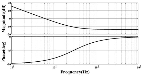
Figure A1.
Amplitude–phase characteristic curve of .
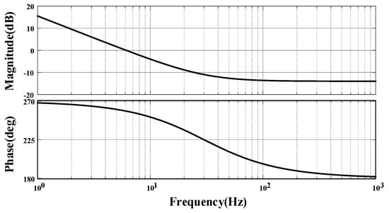
Figure A2.
Amplitude–phase characteristic curve of .
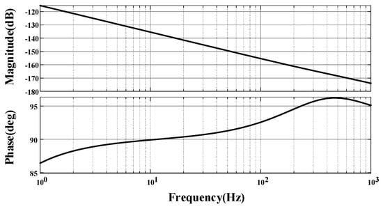
Figure A3.
Amplitude–phase characteristic curve of .
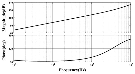
Figure A4.
Amplitude–phase characteristic curve of .
Since , , , , we can obtain .
References
- Zou, X.; Du, X.; Tai, H.-M. Two-Variable Admittance Model for D-PMSG-Based Wind Turbine and Stability Criterion Based on Magnitude and Phase Contour Plot. IEEE Trans. Power Electron. 2020, 35, 1484–1498. [Google Scholar] [CrossRef]
- Zhan, Y.; Chen, W.; Xie, X. Frequency domain mode analysis of sub-synchronous oscillation in grid-connected wind power systems. Autom. Electr. Power Syst. 2020, 44, 90–97. [Google Scholar]
- Liu, B.; Li, Z.; Dong, X.; Samson, S.Y.; Chen, X.; Oo, A.M.; Lian, X.; Shan, Z.; Liu, X. Impedance Modeling and Controllers Shaping Effect Analysis of PMSG Wind Turbines. IEEE J. Emerg. Sel. Top. Power Electron. 2021, 9, 1465–1478. [Google Scholar] [CrossRef]
- Liu, B.; Li, Z.; Zhang, X.; Dong, X.; Liu, X. Impedance-Based Analysis of Control Interactions in Weak-Grid-Tied PMSG Wind Turbines. IEEE J. Emerg. Sel. Top. Circuits Syst. 2021, 11, 90–98. [Google Scholar] [CrossRef]
- Du, W.; Dong, W.; Wang, H. Small-Signal Stability Limit of a Grid-Connected PMSG Wind Farm Dominated by the Dynamics of PLLs. IEEE Trans. Power Syst. 2020, 35, 2093–2107. [Google Scholar] [CrossRef]
- Du, W.; Wang, Y.; Wang, Y.; Wang, H.F.; Xiao, X. Analytical Examination of Oscillatory Stability of a Grid-Connected PMSG Wind Farm Based on the Block Diagram Model. IEEE Trans. Power Syst. 2021, 36, 5670–5683. [Google Scholar] [CrossRef]
- Liu, F.; Li, Y.; He, G.; Li, G.; Liu, S.; Small, W.L. Signal Modeling and Stable Operation Strategy Analysis of direct-drive wind power grid-connected Converter in Extremely Weak Current Network. Electr. Power Autom. Equip. 2022, 42, 167–173. [Google Scholar]
- Wang, D.; Sun, H.; Huang, B.; Han, Y.; Mao, Y.; Zhu, T. Stability Analysis of Voltage Source Direct Drive Wind Turbine Connected to the Grid Based on Virtual Synchronous Control. High Volt. Technol. 2022, 48, 3282–3294. [Google Scholar]
- Shen, Y.; Ma, J.; Li, P.; Huo, Q.; Sun, S.; Huang, Y.; Zhao, S. Subsynchronous Oscillation suppression Strategy of Virtual synchronous doubly-fed Fan with Additional energy branch. Autom. Electr. Power Syst. 2022, 46, 83–93. [Google Scholar]
- Liu, H.; Zhang, X.; Li, Y.; Fu, Y.; Qin, L. Virtual Axis Control and Transient Energy Transfer for Double-fed Wind Turbine. In Proceedings of the CSEE, Sanya, China, 25–27 February 2022; Volume 42, pp. 7007–7019. [Google Scholar]
- Zhang, X.; Huang, Y.; Fu, Y. Analysis of transient Energy Transfer and Oscillation Characteristics of doubly-fed wind Turbine under Nonlinear Elastic Coupling. Trans. China Electrotech. Soc. 2024, 39, 1–19. [Google Scholar]
- Liu, C.; Han, J.; Shang, L.; Dong, X.; Xie, X. Modeling and Quantitative Analysis of wide-frequency oscillation mechanism of new energy Transmission System from the perspective of energy. Power Grid Technol. 2023, 47, 3980–3993. [Google Scholar]
- Ma, J.; Xu, H.; Li, X. Transient Stability Mechanism of direct-drive grid-connected Wind Power System under Strong Interaction. In Proceedings of the CSEE, Shanghai, China, 27–29 February 2024; pp. 1–13. [Google Scholar]
- Jia, K.; Liu, Q.; Yang, B.; Hou, L.; Fang, Y.; Bi, T. Fault Transient Current Analysis of Inverter with PLL Dynamic Characteristics. Power Grid Technol. 2021, 45, 4242–4251. [Google Scholar]
- Ma, J.; Gu, Y.; Shen, Y.; Zhou, Y.; Cheng, P. Stability Analysis of Power Grid Connected with Direct-Drive Wind Farm Containing Virtual Inertia Based on Integrated Dissipation Energy Model. IEEE Trans. Sustain. Energy 2021, 12, 2378–2392. [Google Scholar] [CrossRef]
Disclaimer/Publisher’s Note: The statements, opinions and data contained in all publications are solely those of the individual author(s) and contributor(s) and not of MDPI and/or the editor(s). MDPI and/or the editor(s) disclaim responsibility for any injury to people or property resulting from any ideas, methods, instructions or products referred to in the content. |
© 2024 by the authors. Licensee MDPI, Basel, Switzerland. This article is an open access article distributed under the terms and conditions of the Creative Commons Attribution (CC BY) license (https://creativecommons.org/licenses/by/4.0/).