Abstract
Bioinspired approaches tend to mimic some biological functions for the purpose of creating more efficient and robust systems. These can be implemented in both software and hardware designs. A neuromorphic software part can include, for example, Spiking Neural Networks (SNNs) or event-based representations. Regarding the hardware part, we can find different sensory systems, such as Dynamic Vision Sensors, touch sensors, and actuators, which are linked together through specific interface boards. To run real-time SNN models, specialised hardware such as SpiNNaker, Loihi, and TrueNorth have been implemented. However, neuromorphic computing is still in development, and neuromorphic platforms are still not easily accessible to researchers. In addition, for Neuromorphic Robotics, we often need specially designed and fabricated PCBs for communication with peripheral components and sensors. Therefore, we developed an all-in-one neuromorphic system that emulates neuromorphic computing by running a Virtual Machine on a conventional low-power CPU. The Virtual Machine includes Python and Brian2 simulation packages, which allow the running of SNNs, emulating neuromorphic hardware. An additional, significant advantage of using conventional hardware such as Raspberry Pi in comparison to purpose-built neuromorphic hardware is that we can utilise the built-in physical input–output (GPIO) and USB ports to directly communicate with sensors. As a proof of concept platform, a robotic goalkeeper has been implemented, using a Raspberry Pi 5 board and SNN model in Brian2. All the sensors, namely DVS128, with an infrared module as the touch sensor and Futaba S9257 as the actuator, were linked to a Raspberry Pi 5 board. We show that it is possible to simulate SNNs on a conventional low-power CPU running real-time tasks for low-latency and low-power robotic applications. Furthermore, the system excels in the goalkeeper task, achieving an overall accuracy of 84% across various environmental conditions while maintaining a maximum power consumption of 20 W. Additionally, it reaches 88% accuracy in the online controlled setup and 80% in the offline setup, marking an improvement over previous results. This work demonstrates that the combination of a conventional low-power CPU running a Virtual Machine with only selected software is a viable competitor to neuromorphic computing hardware for robotic applications.
1. Introduction
In the last few years, Artificial Intelligence (AI) has exponentially increased in everyday usage. However, each model typically requires a huge amount of resources, requiring sometimes an energy consumption of thousands of MWh for the training phase and of hundreds of MWh for the running phase [1]. Although Artificial Neural Network (ANN) models are inspired by the brain, they are far from the operational efficiency of the human brain. In fact, the human brain consumes no more than 20 W of power [2] to perform all kinds of complicated tasks compared to the classic AI systems that can require megawatts of energy. Similarly, robotic applications benefit greatly from the neuromorphic paradigm in terms of low-power and low-latency operations [3]. This aspect has stimulated some university labs and companies to build so-called neuromorphic hardware, which is able to mimic biological behaviors in the operational principles of the hardware. Regarding bioinspired robotics, there are many different realizations related to the sensing, computing, and execution of mechanical actions, which are developed for solving tasks such as obstacle avoidance [4,5], object tracking [4,6], playing games such as rock–paper–scissors [7], mimicking biological behavior [8], and similar tasks. Regarding the computing platforms, both conventional and neuromorphic hardware have been implemented. For example, conventional platforms such as microcontrollers [9,10], FPGAs [5], LEGO [11], laptops [12] and cloud computing have been reported. Regarding neuromorphic computing hardware [13], devices such as SpiNNaker [14], Loihi [15], and TrueNorth [16] are available, as well as custom-built platforms such as those that utilise memristive [17] or spintronic devices [18], but not all of them have been used in the context of robotic applications [19]. Robotic platforms also require sensory inputs and actuators. Some platforms utilise conventional sensing devices such as ultrasound [4], LED photodiodes, tactile [20] sensors, etc. However, neuromorphic sensory devices have been developed as well, such as Dynamic Vision Sensors (DVSs or silicon retina), silicon cochlea, etc. [21]. A DVS is a camera that produces signals based on light intensity changes and avoids unnecessary data generation [22].
Models for processing information and decision making for neuromorphic robotics typically rely on the ANN paradigm, such as Spiking Neural Networks (SNNs) [3,23]. SNNs encode the information into asynchronously generated spikes, transmitted between the neurons of the network through synapses, replicating the natural behaviour of the brain. This aspect implicitly includes the time component (in the spike order), which is used for solving various dynamic tasks evolving in time, e.g., object tracking or obstacle avoidance.
Once the robot hardware and the neural network are set up, the difficult task of training the robot to learn the desired task or behaviour begins. Regarding learning algorithms for SNNs deployed on robotic platforms, several approaches have been proposed, such as Spike-Time-Dependent Plasticity (STDP), Reward- or Reinforcement-Based STDP (such as R-STDP [24]), fast-weight STDP [12], Conditioning [11], and Dopamine-Modulated STDP [4,20]. STDP, in combination with lateral inhibition, is typically used for unsupervised learning [25,26]; however, for supervised learning, a reward signal is needed. Alternatively, for supervised learning, a well-known backpropagation algorithm could be used, but it is adapted for SNNs such as in SpikeProp [27]. However, traditional learning algorithms are still a challenge when implemented for robotic applications.
The possibility of physically simulating the behaviour of biological systems leads to two main advantages: the implementation of brain-inspired low-power intelligent systems and the investigation of the brain’s operation via simulations. With these motivations, and with the awareness that dedicated neuromorphic hardware is not always readily available to those who wish to experiment with it—and even when available, the connectivity to external devices could be complicated—we investigated how to enable running real-time robotic applications based on SNNs using conventional low-power hardware.
For this purpose, we propose a neuromorphic robotic system that uses the Brian2 simulation platform, which runs on a low-power convectional CPU, specifically Raspberry Pi, in combination with a DVS camera, touch sensor, and a digital motor. The key novelty is to combine and implement two readily available and easy-to-use elements in a robotic setup: (i) Brian2 software for designing and running SNNs and (ii) a Raspberry Pi board for executing the SNN code and communication with external devices. Crucially, Brian2 has been proven to be able to cope with real-time input [28].
There are Operating Systems (OSs) that are purpose-built for neuromorphic hardware (such as SpiNNaker, Loihi, and TrueNorth) and that could be optimised for the partitioning and mapping of SNNs [29]. However, another approach (used in this work) is to rely on a conventional OS deployed on a microprocessor and simulation programming in common programming language (Python, C++, Java and so on) running on a PC.
As an experimental demonstrator, we implement a robot goalkeeper based on a DVS128 camera, working as an eye sensor, a Futaba S9257 actuator, working as an arm, and an infrared sensor, working as a touch sensor. All these devices are connected to a Raspberry Pi 5 board [30], using USB and GPIO connections; see Figure 1. On this low-power processor, we run an SNN model on a Virtual Machine, communicating with the sensors to predict the final goalkeeper position. The main purpose of this work is to demonstrate that we can use a conventional CPU in combination with a Virtual Machine for robotics applications as a replacement for a purpose-built neuromorphic hardware.
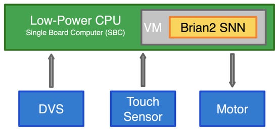
Figure 1.
The block diagram of the proposed neuromorphic robotic system, consisting of neuromorphic hardware units (DVS), a touch sensor and digital motor, linked to a low-power Single Board Computer (SBC). A Virtual Machine (VM) runs on the SBC and hosts a Brian2 instance. This configuration allows for running Spiking Neural Networks (SNNs), which process the sensory inputs and make decisions that are passed to the executive (e.g., motor) units.
The paper is organised as follows. In Section 2, we describe the methodology of our work, explaining how the sensors are connected to a Raspberry Pi 5 board, both physically and logically. In Section 3, we report our results, measuring the accuracy in predicting the correct goalkeeper position, the power consumption of the whole system and the reaction time for real-time evaluation. Finally, in Section 4, we compare our results with those of previously implemented systems addressing similar tasks.
2. Materials and Methods
In this section, we present our neuromorphic robotic platform and the communication between components. We begin by explaining the physical links between the devices, and then we describe the software side, including input preprocessing, SNN model simulation and synchronisation mechanisms.
2.1. General Concept of Conventional CPU as Neuromorphic Hardware
The general idea of turning a conventional low-power CPU into neuromorphic hardware resides on the need to have an affordable and easily accessible alternative to SNN hardware, which was combined with dedicated, purpose-built interface boards (needed to connect sensors). Our proposed system aims to abstract the neuromorphic computational hardware by using a Virtual Machine (VM) on an existing host operating system, leveraging the physical connections of a low-power Single Board Computer (SBC). The use of a SBC simplifies the connectivity of external hardware like vision and hearing sensors and actuators, exploiting the onboard connections provided by the SBC. Figure 1 shows our general concept, where the green box represents the low-power SBC that runs the VM. The external devices are presented with the blue boxes. On the SBC, a Virtual Machine hosts a Python and Brian2 [28] instance, which is running the SNN model and performs all the communication tasks at a logic level. All the device drivers are also included in the VM.
Some previous examples where neuromorphic devices have been successfully emulated by a combination of conventional devices and software exist. For example, there was the behavioural emulation of event-based vision sensor, where an inexpensive high frame-rate USB camera was used to emulate an activity-driven vision sensor [31].
2.2. System Specification
To demonstrate the feasibility of our proposed concept, we have built a demonstrator system, which has as its task to observe an incoming object and try to intercept it, as illustrated in Figure 2. Our demonstrator system is based on the Raspberry Pi 5 SBC that mounts the Broadcom BCM2712 quad-core Arm Cortex A76 processor running at 2.4 GHz with 8 GB of RAM [30]. The DVS128 [32] camera is directly connected to the SBC through a USB connection. The communication is managed by the native libcaer [33] driver that allows us to decode the AER packets coming from the DVS and facilitates the configuration of different aspects such as noise reduction and packet batch size. The advantage of using a USB connection lies in the flexibility of swapping or adding sensors by simply selecting the appropriate driver without changing the system structure. The DVS data is pre-processed by the Control Unit (frequency conversion) and is then sent to the SNN model. The Infrared sensor (IR), which acts as a touch sensor, and the Servo actuator (the motor unit) are directly connected to the SBC’s GPIO ports. Native GPIO libraries manage the data communication between the physical devices and the virtual components. At a higher level, the Core Unit represents the main elaboration unit of our system, which is responsible for integrating the sensors with the predictive SNN model.

Figure 2.
The Neuromorphic Robotic Goalkeeper platform developed in this work. (Left-Bottom): The goal, the goalkeeper and incoming balls which are representing the tasks for the robot. (Left-Top): The DVS camera and how the camera represents the visual scene. (Right): Data flow from the DVS input to the goalkeeper positioning. All hardware elements on the Raspberry Pi are grouped together in the green box, and the software parts are grouped together in the blue box (Virtual Machine). Brian2 runs the SNN simulation (yellow box) that returns the predicted position for the goalkeeper, which sets the final goalkeeper position, driving the digital servo motor. The touch sensor signal is received by the Virtual MCU and sent to the Control Unit, which passes it to the SNN (e.g., as a reward signal).
Following the data flow in Figure 2, the input data from the DVS are collected by the Control Unit (CU) using the PyAer wrapper python library, pre-processed and then converted into frequencies. The processed data are stored in a shared memory, making it accessible to the Decision Unit (DU) where the model is running. At this stage, the manager units operate at a high level in a VM using different threads to optimise the process parallelisation. For this reason, the option of using a shared memory for transmitting input data is crucial, especially with a high frequency transmitting rate of the DVS, operating on the order of microseconds. The DU hosts an instance of the Brian2 framework, which facilitates the simulation of a Spiking Neural Network on a common CPU with a high level of abstraction from the mathematical model. Since real-time prediction is essential for robotic applications, it is necessary to synchronise real time with emulation time in order to strike an optimal balance to achieve short simulations with minimal delay. To prevent data loss due to delays, the input data are converted into the frequency domain, representing it as the spike rate for a Poisson Generator input object. The output from the simulation is periodically monitored by combining monitors and Network Operations. This approach allows for immediate result retrieval and compensates for execution delays, thereby eliminating the need to wait for the simulation to complete. Finally, direct socket communication with the Virtual Microcontroller Unit (MCU) is used to set the final position of the arm.
The events from the touch sensor are intended for reinforcement learning in the SNN model; although not utilized in this work, they will be incorporated in a future SNN model that includes a reward signal for learning. More detailed time sequence diagrams, illustrating the interactions between the hardware and software components, along with further explanations, can be found in Appendix A.
2.3. Control Unit
The Control Unit is the central logic component responsible for managing all incoming and outgoing signals between the physical devices (see Figure 2). Input data from the DVS camera are interpreted by the PyAer [34] library, which leverages the libcaer driver installed on the host OS. This driver decodes the Address Event Representation (AER) packets generated by the DVS camera. These packets are produced when a pixel detects a change in light intensity, capturing only the relevant information. This approach contrasts with traditional cameras that capture entire images at specific time intervals, including redundant background details. The event data are transmitted in batches of packets, each including a time stamp as well as the -coordinates of the spiking pixel, the type of event (on/off), and the noise flag. During the pre-processing phase, the data are cleaned of noise and converted into frequencies, which are then sent to the SNN. Converting the data into the frequency domain reduces the number of spikes sent to the network while preserving critical changes in information. As already mentioned, each unit runs on a separate thread to enhance speed and avoid blocking operations. There are two communication techniques used to interface with other units. For the Decision Unit, which runs the SNN model, two shared memories are used for input (ISM) and output (OSM) communication. The Control Unit writes new available data into the ISM, while the Decision Unit has read-only privileges. Simultaneously, the results from the Decision Unit are written into the OSM, which the Controller Unit reads, enabling real-time bidirectional communication. The communication with the MCU Unit is handled via a client/server connection. The touch Controller reads the IR state, from the MCU Unit, and writes it into the ISM. Similarly, the Motor Controller reads data from the OSM and sends a request to the MCU Unit to set the final arm position.
2.4. Virtual MCU
The Virtual MCU is responsible for receiving feedback from the IR sensor and setting the servo motor position. The communication with physical devices is performed through the gpiozero [35] library and the Raspberry Pi GPIO23 and PWM0 GPIO18 ports, which are used for IR and Servo, respectively (Table 1, see also Appendix B, Figure A3). As mentioned earlier, this unit operates independently and hosts a local web server, using the Python Flask [36] framework to set and receive data. This design choice helps prevent blocking operations caused by delays in setting and positioning the servo motor. To avoid servo jittering, due to there being a continuous PWM setting, the servo communication is paused after the angle information is sent. This operation is not executed immediately after setting the angle but requires some delay time to wait for the complete PWM transmission. This delay has been set to 100 ms, which is also the maximum time required for the servo motor to mechanically reach its final position.

Table 1.
Raspberry Pi 5 SBC link with others components. Hardware scheme is shown in Figure A3.
2.5. Decision Unit
In the Decision Unit, a Brian2 framework instance hosts the SNN model which receives pre-processed input data and predicts the final goalkeeper position. The use of Brian in real time has been demonstrated previously, in [28], where C++ code was directly included in the model to communicate with hardware in a compiled version. However, in our approach, we employ a slightly different method that focuses on running units independently and parallelising processes while maintaining high-level programming approach. A typical data flow for DVS input and positioning is shown in Figure 3.

Figure 3.
Synchronisation timeline. The timeline shows the model synchronisation for real-time application. The RT line represents the real time in batches of 50 ms. The DVS data are continuously read by the Control Unit each 500 μs, forwarding it to the SNN model every 1 ms. The SNN model simulation runs in a time window of 50 ms, allowing to synchronise the next run using a computed delay. The output is read every 1 ms and used to set the goalkeeper position, which requires a mechanical positioning time of up to 100 ms.
The crucial aspect of executing an SNN for real-time application is the need to align the simulation time with the actual time, as shown in Figure 3. This is made possible by setting specific parameters configurations to keep a good simulation detail but still running in a real or sub-real time (simulation time is faster than real time). To control the time alignment, executions are performed in steps of 50 ms, checking the time delta at each execution. The computed delta time difference is then used as waiting time before running the next simulation step. Since the input events from the DVS are recorded and converted into frequencies, this delta time is compensated and used in the next simulation step without losing a significant amount of information. It is necessary to take into account that for real-time applications, it is not acceptable to wait for 50 ms before injecting new data into the model and reading resulting data, even in the frequency domain. To overcome this lack of information, Brian2 network operations are used to inject input data and read output spikes during the simulation with a period of 1 ms. This technique reduces the data delay to 1 ms for both input and output communication. Network operations serve as the entry and exit points for the model; at each step, the Shared Memory Input (SMI) is accessed to read new frequencies, which are then set in the first layer of the SNN. A Brian monitor object is used to capture the resulting spikes in the output layer, which are subsequently written as frequencies in the Shared Memory Output (SMO). This approach ensures that the system operates with minimal latency, preserving the integrity of real-time processing.
SNN Models
For the purpose of running a real-time SNN simulation on low-power CPU, we propose two SNN models that include input neurons, synapses and output neurons. These networks are shown in Appendix C. The first model (Figure A4a) is a simple model consisting of an input layer with eight neurons linked in a 1-to-1 way to eight output neurons. Each of these eight input neurons has a spike frequency which represents the spike count from a block of 16 (along x-axis) × 128 (along y-axis) pixels. The second model (Figure A4b) consists of 128 input neurons connected to eight output neurons. In this case, the input neurons are not grouped in blocks of 16; instead, each block is 1 × 128 pixels. The purpose of the second model is to test the hardware performance on a larger network. In both models, the input layer is a Poisson Generator group that receives the spiking rate from the Control Unit. The output layer has the same characteristics in both models and is composed of eight conductance-based (COBA) Leaky Integrate-and-Fire (LIF) neurons, which represent the final arm positions. The following system of differential equations describes the output neurons membrane voltage (v) behavior in time:
where is the membrane resting potential, is the reversal potential, is the synaptic conductance, and is the membrane time constant. The synaptic conductance is also decaying by the rate. When the membrane potential reaches the threshold value (), a spike is generated by the neuron, and the membrane potential is reset to the reset value (), where it stays for a refractory period (). There is no learning rule in these models; so the only information transmitted to the output layer is an event changing the conductance of the post-synaptic neuron when a pre-synaptic neuron spikes. We use an on_pre event to model this in Brian. The model parameters are shown in Table 2.

Table 2.
Default SNN parameters for the simulation.
2.6. Software Stack
The software stack developed for our neuromorphic computing and robotic applications is presented in Figure 4. It consists of four abstraction levels, L1 to L4 from the bottom to the top layer, respectively. The L1 layer represents the Hardware layer, which includes the Raspberry Pi 5 SBC along with the sensors (DVS128 and IR) and servo motor. At level L2, the Operating System hosts all the necessary services and libraries to enable the communication with the L1 level. The middle layer (L3) is composed of the drivers that allow the top layers to send and receive data. Just below the top layer (L4), the Python VM is responsible for running all the virtual units that rely on four frameworks (PyAer, Brian2, Flask, Gpiozero).
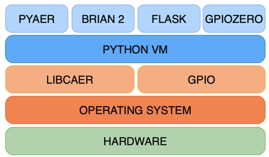
Figure 4.
System stack representing the different abstraction levels. From the bottom, level 1 is the hardware level, composed by the SBC, DVS, sensors and actuator. At level 2, the Operating System (Linux) runs on the hardware and hosts all services and virtual units. At level 3, we find the two main drivers, libcaer and gpio, enabling the communication with the hardware level. At the high level, L4, the Virtual Machine contains and runs all the three units, which are supported by the PyAer and Brian2 frameworks for the prediction and by the gpiozero and Flask frameworks for the positioning.
3. Results
The proposed system, described above, has been designed to replicate the goalkeeper task on low-power SBC, allowing it to be powered by a small battery pack for mobility purposes. To evaluate the system performance’s different metrics, latency, accuracy, resources consumption and power consumption have been measured. In this section, we report the results of our tests for the real-time application of our system.
3.1. Latency
The prediction task latency in our system consists of the cumulative time required to receive the input signal, pre-process it, transfer it to the SNN, calculate the prediction of the goalkeeper position, communicate that information to the servo motor, and use the motor to move the arm to its final position. As mentioned in [32], the DVS camera produces events each microsecond and needs an extra 1 μs to communicate it via the serial port. Since we run the model in time steps of 1 ms, we set the transmission rate from the DVS to 500 μs like in our previous realisations of the system [6,10], leaving enough time for the pre-processing step. As a consequence, we cannot consider latency time for receiving data from the DVS and elaborate it in the Control Unit for longer than 1 ms. The system then immediately forwards the input to the SNN model, which runs the simulations in 50 ms batches. At this point, the Network Operation object injects the received input at 1 ms time steps, with the response delay depending on the volume of incoming data. Additionally, while input is being injected, the output monitor continuously looks for output spikes, which are immediately forwarded. When the input is sufficient to trigger a spike in the output neurons, the minimum delay for the model answer is 1 ms for input and 1 ms for output. Considering negligible time for memory access and code execution, the computation latency time is about 3 ms. The remaining delay is attributed to the arm positioning (75 ms for 60° positioning + 1 ms for receiving instructions with the HTTP protocol), resulting in a maximum delay of 154 ms (optimised to 100 ms with position reset).
3.2. Resources Consumption
To measure the system performance, we ran the system on a 5 V battery pack (capacity 12,500 mAh) and executed an independent script to record the CPU power usage, consumption and temperature, memory consumption, and battery power consumption. The recording was conducted over 70 min, leaving the system idle for the first 5 min, followed by 1 h of model execution, and then 5 min of cooling down; see Figure 5. The CPU drew a current of 4–7 A (average about 6 A) during the execution (CPU voltage of 1.2 V)—see panel (a). The CPU usage percentage immediately jumped to the maximum level and remained above 80% for the entire execution time—panel (b). The CPU temperature stabilised between 60 and 65 °C—panel (c). However, looking at the steps before and after the execution (idle and cooling down), the CPU ran at 2.2 A on average, meaning that the model consumes 3.8 A on average (i.e., 4.56 W at 1.2 V). For a complete system consumption, we measured the battery level change in percentage (panel (b)—red line). As we can see, the battery level linearly decreased to about 2/3 of its capacity after 1 h running, corresponding to an overall consumption rate of about 20 W (4 A at 5 V). The main memory (RAM) usage when all units were running ranged from 750 to 800 MB during the 1 h execution. However, during the idle phases (the first and last 5 min), the system memory usage was around 520 MB before the execution and 550 MB afterward. This indicates that the model initially consumed approximately 200 MB of memory, which increased by only 50 MB after 1 h of operation.
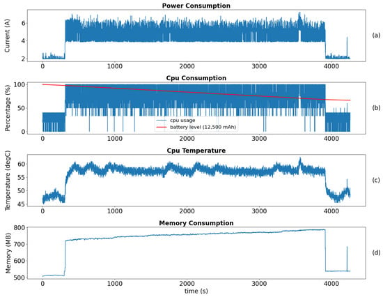
Figure 5.
Consumption of the resources during one hour of simulation, using batteries as the power source. (a) CPU power consumption (expressed as current drawn from the battery). (b) CPU usage during the simulation (the red line represents the battery level, for a battery of 12,500 mAh). (c) CPU temperature. (d) Memory utilisation of the model.
3.3. Accuracy
The accuracy of our system is the ability to predict the correct ball trajectory and stop the ball. In the online scenario, the DVS camera is placed 30 cm above the goal, with a 20 degree negative tilt, aimed at the space in front of the goal; see Figure 6. The accuracy was measured counting the number of the blocked balls over 100 launches from 1 m distance with random speed and direction. To improve accuracy, when the decision is made, the system resets an inactivity timer that is used to replace the goalkeeper to the middle position. This simulates the goalkeeper behaviour of optimising the future intervention for intercepting the ball, reducing the arm positioning time to 75 ms. In case a new ball is coming before the timer expires, the predicted position is directly used to set the arm.
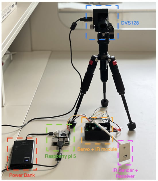
Figure 6.
System configuration: Raspberry Pi 5 SBC (green box) powered by a USB-c power bank with 12,500 mAh capacity (red box), the servo motor with the IR module (orange box), the goalkeeper touch sensor terminal (purple box) and the iniVation DVS128 camera (blue box).
Apart from demonstrating the overall functionality of the system in real time, we also tested the system on a controlled simulated environment. In this (offline) scenario, the input consists of a ball image moving on a screen (instead of a real ball on the table) allowing us to accurately control the ball speed, directions, colour and the background. The rest of the system remains unchanged. The DVS camera is positioned in front of the screen and centered to the simulated Field of View (FOV) to capture the onscreen ball. For the reward signal (touch sensor), the Virtual MCU was replaced with an additional web service that communicates with the balls’ generator software, providing us with accurate information about the ball’s endpoint. This setup allows us to automatically calculate accuracy by validating predictions made before each ball reaches the end of the FOV with an additional maximum delay of 100 ms for arm positioning.
For this offline scenario, we tested the system under different background/target colors and two types of trajectories: (i) in lane, i.e., when the ball direction is precisely within the width of the goalkeeper’s pre-defined position (there are eight of theses positions in our experiment, each covers about 10°) and (ii) random straight trajectories. The results are shown in Appendix D, and there is a summary in Table 3. In the online scenario (i.e., with the real ball), we reached an overall accuracy of 80% of correctly predicted goalkeeper’s positions (SNN128)—a similar accuracy as with the ball moving on a screen from a random position. A confusion matrix result is shown in Figure A5 of Appendix D.

Table 3.
Mean accuracy for different trajectories types and overall accuracy.
We note here that we have used a very simple SNN algorithm, since the aim of this initial work was to develop a proof-of-principle platform for our robotic system, and various optimisation and performance enhancement steps can be implemented later.
4. Discussion
In this work, we focused on the implementation of a neuromorphic robotic platform on a Single Board Computer running an SNN simulation. We configured a Raspberry Pi 5 board with 8 GB of RAM, running a Linux Ubuntu 23 OS. The main advantage of using the Raspberry Pi 5 SBC lies in the possibility of linking all the external components (DVS, servo and IR) to the provided USB and GPIO connection ports, resulting in a simple and compact system. This contrasts with previous projects like [10], where multiple boards and devices were connected using a custom-built PCB. Furthermore, the integration of a USB-C port for powering the board allows the use of compact powerbanks running at the exact voltage without the necessity for level shifters and power regulator chips.
In Table 4, we compare our system with several robotic platforms. First, we compare it with a neuromorphic robotic platform, which utilises a SpiNNaker board for running an SNN as well as a custom-built PCB with needed electronic components, which were designed for a similar task [10] (named here spiNNaLink). Analysing the power consumption, our system consumes about 20 W in an unoptimised state. Unoptimised state means here with full installation of the system, WiFi on, no power safe mode, system services on. That is about three times more that the spiNNaLink system. The positioning time is practically the same as that of spiNNaLink and in line with the other projects. The achieved accuracy depends on the model running on the board, but it is comparable to previous results. For the SNN, we chose to implement a more selective model with a COBA equation to filter the incoming signal and to have a more accurate prediction. With a simple model that ignores capacitance, all the signals would be forwarded to the output, leaving the decision to a simple counting of the output neurons spikes.

Table 4.
Comparisonof our SBC SNN system with neuromorphic robotic platforms.
4.1. Advantages
The proposed system is a combination of neuromorphic hardware, sensors, actuators and a Spiking Neural Network simulator, running on a low-power Single Board Computer (SBC). The choice of using an SBC to link all the external devices and to run the SNN model leads to several advantages. On the hardware side, the possibility of exploiting the native SBC connections increases the compatibility of external devices, avoiding the implementation of custom solutions and protocols. In fact, neuromorphic hardware like DVS cameras often rely on USB connections using their own driver, which are optimised to guarantee the maximum speed and robustness. In addition, the possibility to link sensors and actuators directly to the GPIO pins of the board avoids the implementation of custom interface boards, significantly reducing the transmission latency (no custom protocols are needed). Moreover, no level shifters or power regulators are necessary for the communications of external devices working with different voltages, resulting in a more compact and portable solution.
On the software side, our solution is based on the synchronisation of internal microservices that are driven by the predictive model in real time. Classical ANN and CNN models have been used before to solve similar, or more complicated, tasks utilising a more powerful and energy-demanding hardware like GPUs. In our system, we leverage the Brian2 framework for the simulation of an SNN model that is able to work in real time. Brian2 provides full control and customisation of the neural network model and avoids data loss due to dropping spikes, which are usually present in dedicated neuromorphic hardware. An SNN model, compared to CNN, is better adapted to cope with elaborate event-based inputs. It avoids loss of data that can be present in CNN models (due to a frame-based approach implicit in the model), also resulting in a slower prediction, which is otherwise crucial in real-time applications.
Our approach has a strong scalability. On the hardware side, it only depends on the number of available communication ports on the board. Diverse types of sensors can be added to the system, giving the opportunity to explore sensory fusion. On the software side, the scalability of the SNN, in terms of the number of neurons and synapses, is highly flexible because all simulations are conducted in software. In our case, there are no hardware constraints on the SNN (apart from the speed of execution) in contrast to neuromorphic computing, where the scalability of the network often depends on the scalability of the hardware as the network needs to be mapped directly to the available hardware. Finally, RaspiSNN works as a modular edge computer, allowing the development of a cluster of SBCs to improve the computational power and connectivity if needed.
4.2. Limitations
Despite the results described above, several limitations should be highlighted. Firstly, the real time performance of the model is affected by the SNN’s model complexity and structure. A smaller time-step increases the computation detail over time, affecting the delay inner simulations steps that can lead to overtime of the simulation against the real time. In this work, the minimum time-step that guarantees real-time synchronisation is ms. Additionally, the number of neurons and synapses, and their differential equation model, impacts the complexity and the computation time.
Second, the DVS input is susceptible to environmental conditions. Although the DVS is generally a robust vision system, factors such as artificial lighting, shadows, table background, and ball color can introduce noise, which may affect accuracy. One way to address this would be by integrating filters in the SNN model, to automatically adjust the neurons threshold based on noise, although this will influence the real-time execution.
5. Conclusions
The aim of this work was to develop a neuromorphic robotic system using conventional low-power CPU capable of running an SNN. The Raspberry Pi 5 Single Board Computer was used as the low-power platform to host a hardware connection and high-level logic. Three virtual components, namely the Control Unit (CU), Decision Unit (DU) and Virtual MCU (vMCU) operate concurrently, which are hosted by the Ubuntu OS. The CU manages input data from the external sensors (DVS and IR sensors) and relays decision instructions from the DU to the vMCU. The DU is responsible for predicting the arm position with a Brian2 instance running to simulate the SNN model in real time using external inputs. The results show that the system successfully runs an SNN model in real time with synchronization mechanisms, maintaining power consumption around 20W, which is consistent with similar neuromorphic robotic platforms (Table 4). Additionally, the system’s overall accuracy outperforms our previous work (spiNNaLink), achieving 80% accuracy in offline scenarios and 88% in online scenarios.
To enhance the system’s capabilities, future work will involve testing more complex SNN models with additional layers and learning rules. A self-learning SNN model that includes feedback signals from the infrared sensor is currently under investigation. To address latency issues, the current bottleneck is the servo speed, which could be improved by using a faster motor. Lastly, optimisation of the system to further reduce power and resource consumption will be considered.
Author Contributions
Conceptualisation, N.R. and K.N.; methodology, N.R. and K.N.; software, N.R.; validation, N.R., T.M. and K.N.; writing—original draft preparation, N.R. and K.N.; writing—review and editing, N.R., T.M. and K.N.; visualisation, N.R.; supervision, T.M. and K.N. All authors have read and agreed to the published version of the manuscript.
Funding
This research was funded by the Vice-Chancellor’s Scholarship from the University of West London (N.R.).
Data Availability Statement
Additional resources and instructions are publicly accessible on a Github repository: https://github.com/russonicola/RaspiSNN (accessed on 8 August 2024).
Conflicts of Interest
The authors declare no conflicts of interest.
Abbreviations
The following abbreviations are used in this manuscript:
| AER | Address Event Representation |
| AI | Artificial Intelligence |
| ANN | Artificial Neural Network |
| CNN | Convolutional Neural Network |
| COBA | Conductance-Based (model) |
| CPU | Central Processing Unit |
| CU | Control Unit |
| DC | Direct Current |
| DU | Decision Unit |
| DVS | Dynamic Vision Sensor |
| GHz | Gigahertz |
| GPIO | General Purpose Input/Output |
| IR | Infrared |
| ISM | Input Shared Memory |
| LIF | Leaky Integrate-and-Fire (model) |
| MCU | Microcontroller Unit |
| MW | Megawatt |
| OS | Operating System |
| OSM | Output Shared Memory |
| PCB | Printed Circuit Board |
| PWM | Pulse-Width Modulation |
| RAM | Random Access Memory |
| SBC | Single Board Computer |
| SNN | Spiking Neural Network |
| STDP | Spike-Timing-Dependent Plasticity |
| USB | Universal Serial Bus |
| VM | Virtual Machine |
| W | Watt |
Appendix A
Here, we describe the two main algorithms responsible for the Input/Output signal control (Control Unit Algorithm) and for the Spiking Neural Network simulation (Decision Unit Algorithm). In addition, a comparison between the two units’ flow is shown in a block diagram and in a sequence diagram.
Appendix A.1. Control Unit Algorithm
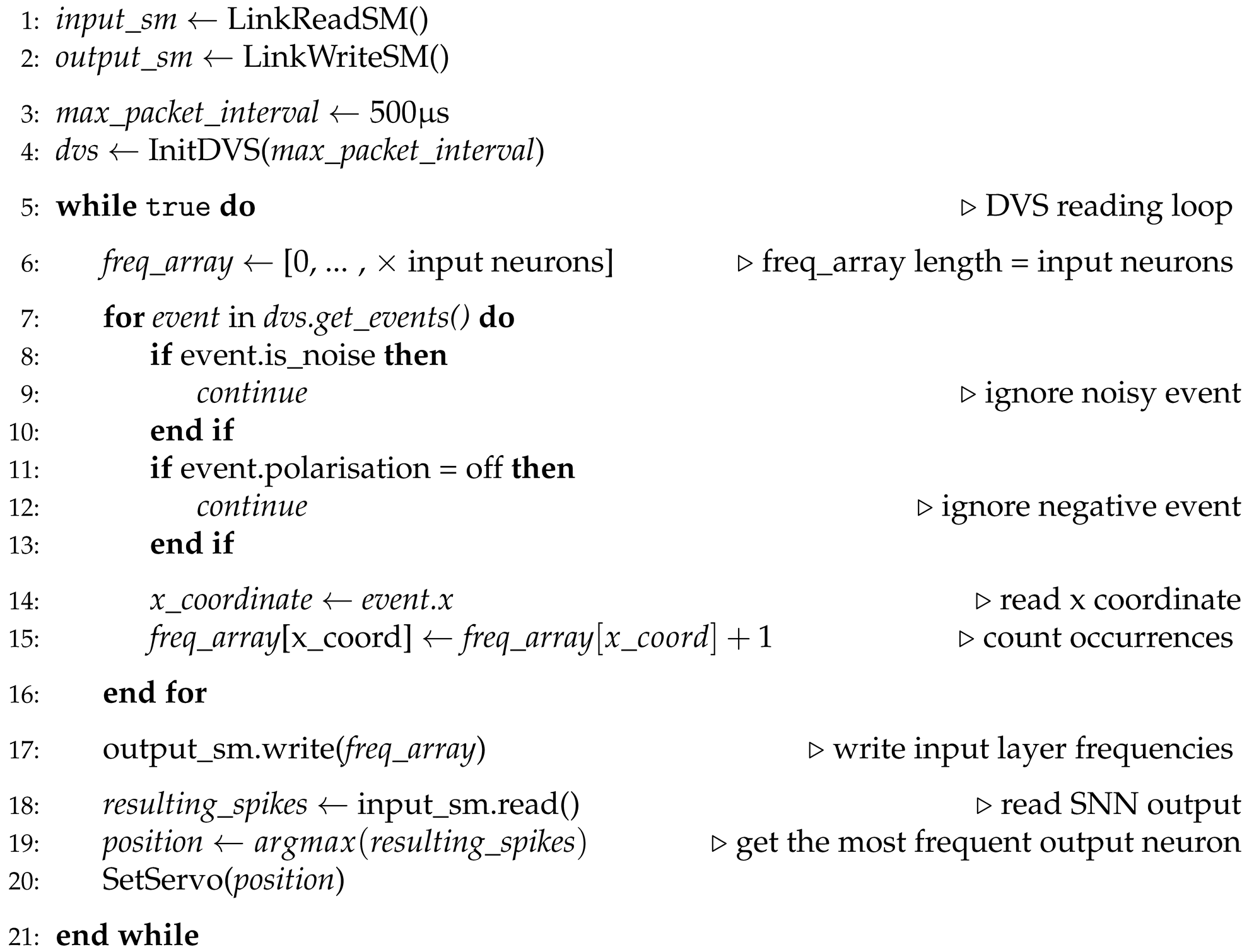
In the proposed system, the Control Unit (Algorithm A1) is responsible for the communication between the hardware components (DVS, actuator, sensors) and the Decision Unit. The main role of this unit is to read the DVS input (line 7) and forward it to the Decision Unit (line 17). The input is retrieved each 500 s, and it is converted into frequencies. Simultaneously, the Control Unit reads the output shared by the Decision Unit (line 18), which is used to set the servo position (line 20).
| Algorithm A1 Control Unit algorithm |
 |
Appendix A.2. Decision Unit Algorithm
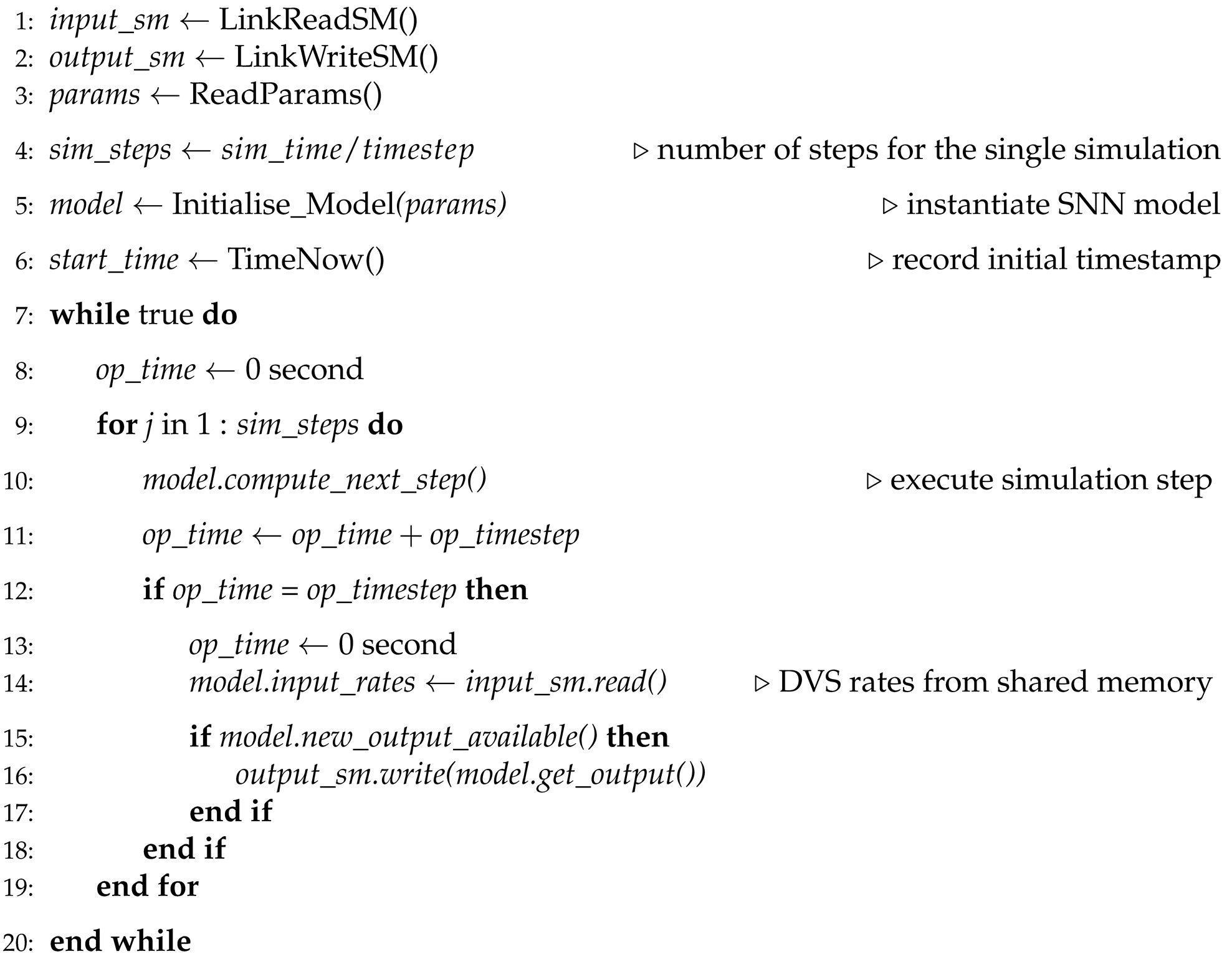
This unit that is responsible for running the Spiking Neural Network model is the Decision Unit (Algorithm A2). Like in the Control Unit, data are shared via two channels’ shared memory, line 14 for the input coming from the CU, and line 16 for the output decision. Each simulation step is executed inside the loop (block 9–19) that includes internally the Network Operation function (block 12–17). The purpose of the Network Operation function is to periodically check for available input/output data to share with the Control Unit.
| Algorithm A2 Decision Unit Algorithm |
 |
Appendix A.3
To better understand how the Control Unit (CU) and the Decision Unit (DU) interact, we present a block diagram with input, output and operations (Figure A1). In the diagram, it is possible to see how the shared input memory is written by the CU and read by the DU, and, in the same way, the shared output memory is written by the DU and read by the CU (yellow parallelogram blocks linked with dashed arrows).
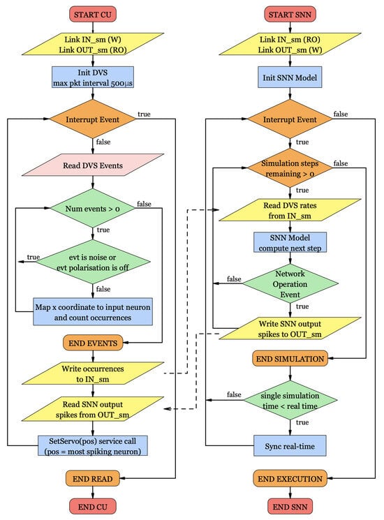
Figure A1.
Block diagram showing the Control Unit and Decision Unit algorithms’ flow and their interaction. The yellow parallelograms represent the in and out shared memory areas where the two units transmit data. The Control Unit has write privileges for the Input memory, where the DVS events are written, and a read-only access to the Output memory, where it reads the predicted position. The Decision Unit can access the Input memory to read the input from the DVS, while it can write the results in the Output memory.
Appendix A.4
A typical flow sequence of data flowing from the DVS to the final position to set is shown in the sequence diagram in Figure A2. The green and blue boxes represent the hardware and software components, respectively. Input from the DVS is buffered for 500 μs and sent in blocks to the Control Unit, which pre-processes and writes it in the Input shared memory. The Decision Unit reads periodically with the Network Operation function the data from the Input memory and forwards it to the SNN, setting the neurons’ rates. When the output from the SNN is available, the Decision Unit writes it in the Output shared memory. At this point, the Control Unit reads the available output from the Output shared memory and uses it to call the set_servo function in the Virtual MCU, which then sets the final arm position.
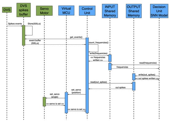
Figure A2.
Sequence diagram for the signal and data flow presented in Figure A1.
Appendix B
Here, we show the hardware wiring schematic of the proposed system (Figure A3). The Futaba S9257 pulse data pin is wired to the GPIO12 of the Raspberry Pi board. The Infrared module data are wired to the GPIO16. Both the servo and IR module are powered with a 5 V DC current. The DVS camera is connected to a USB port. The whole system is powered with a 5 V power bank linked to the Raspberry Pi USB-C port.
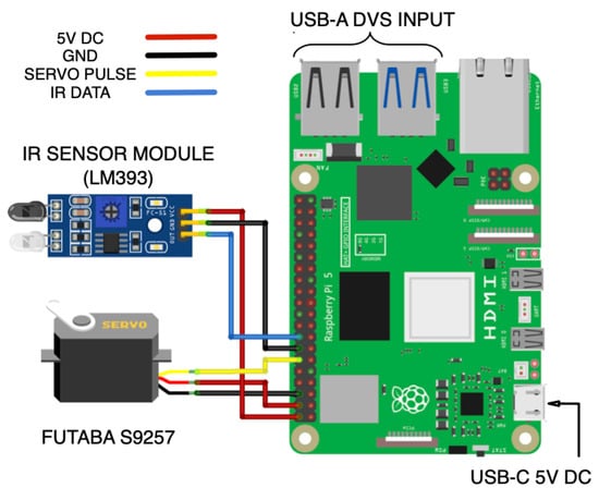
Figure A3.
Schematic of the implemented system.
Appendix C
For the purpose of demonstrating the robotic system that we have developed in this paper, we use two simple SNNs, which are both shown in Figure A4. We note here that they only serve a proof-of-concept purpose, and more elaborate, reinforcement learning networks will be developed in future work.
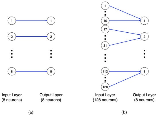
Figure A4.
SNN architecture for the two presented models. On the left (a), a simple (proof-of-concept) model consisting of 8 input neurons and 8 output neurons, linked with 1-to-1 synapses. On the right (b), a more complex model that takes as input all the 128× column pixels of the DVS, which is composed of 128 input neurons and 8 output neurons. The input layer is linked to each of the 8 output neurons in groups of 16 input neurons.
Appendix D
In this section, detailed experimental results are reported.

Table A1.
Mean accuracy for the robotic system controlled by two SNN models (SNN128 and SNN8) run on a laptop and Raspberry pi for different environment conditions (i.e., the background and ball colour) and ball speeds (which were set to four values: 0.5, 1, 2 and 4 m/s).
Table A1.
Mean accuracy for the robotic system controlled by two SNN models (SNN128 and SNN8) run on a laptop and Raspberry pi for different environment conditions (i.e., the background and ball colour) and ball speeds (which were set to four values: 0.5, 1, 2 and 4 m/s).
| Model | Background | Ball | Speed (m/s) | Accuracy Labtop | Accuracy RaspiSNN |
|---|---|---|---|---|---|
| SNN128 | black | white | 0.5 | 0.775 | 0.775 |
| SNN128 | black | white | 1.0 | 0.85 | 0.775 |
| SNN128 | black | white | 2.0 | 0.8125 | 0.7625 |
| SNN128 | black | white | 4.0 | 0.875 | 0.8 |
| SNN128 | white | black | 0.5 | 0.8 | 0.7625 |
| SNN128 | white | black | 1.0 | 0.875 | 0.8 |
| SNN128 | white | black | 2.0 | 0.8625 | 0.825 |
| SNN128 | white | black | 4.0 | 0.7625 | 0.7 |
| SNN8 | black | white | 0.5 | 0.775 | 0.85 |
| SNN8 | black | white | 1.0 | 0.7875 | 0.7375 |
| SNN8 | black | white | 2.0 | 0.825 | 0.8125 |
| SNN8 | black | white | 4.0 | 0.85 | 0.7625 |
| SNN8 | white | black | 0.5 | 0.75 | 0.775 |
| SNN8 | white | black | 1.0 | 0.875 | 0.8875 |
| SNN8 | white | black | 2.0 | 0.7625 | 0.825 |
| SNN8 | white | black | 4.0 | 0.725 | 0.75 |
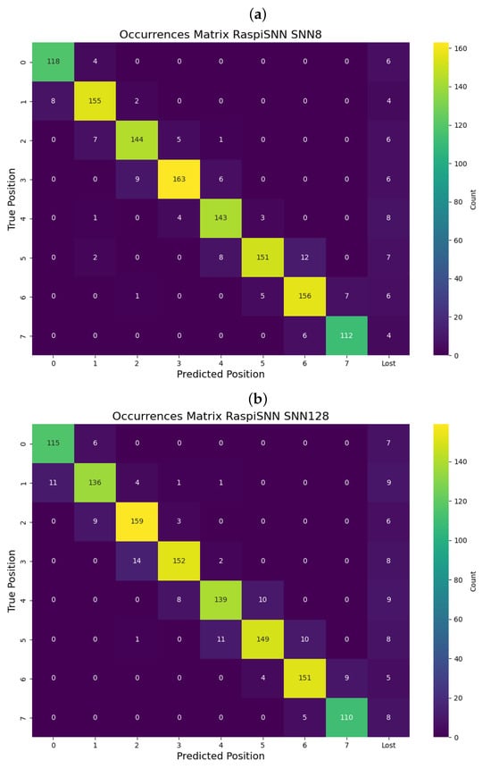
Figure A5.
Confusion matrix for predicted goalkeeper’s position vs. actual ball position for (a) SNN8 and (b) SNN128. There is an additional column which shows rare events when the network did not respond to the visual input, and the goalkeeper was not moved.
References
- Patterson, D.; Gonzalez, J.; Hölzle, U.; Le, Q.; Liang, C.; Munguia, L.-M.; Rothchild, D.; So, D.; Texier, M.; Dean, J. The Carbon Footprint of Machine Learning Training Will Plateau, Then Shrink. Computer 2022, 55, 18–28. [Google Scholar] [CrossRef]
- Balasubramanian, V. Brain Power. Proc. Natl. Acad. Sci. USA 2021, 118, e2107022118. [Google Scholar] [CrossRef] [PubMed]
- Bing, Z.; Meschede, C.; Röhrbein, F.; Huang, K.; Knoll, A.C. A Survey of Robotics Control Based on Learning-Inspired Spiking Neural Networks. Front. Neurorobot. 2018, 12, 35. [Google Scholar] [CrossRef]
- Liu, J.; Lu, H.; Luo, Y.; Yang, S. Spiking neural network-based multi-task autonomous learning for mobile robots. Eng. Appl. Artif. Intell. 2021, 104, 104362. [Google Scholar] [CrossRef]
- Liu, J.; Hua, Y.; Yang, R.; Luo, Y.; Lu, H.; Wang, Y.; Yang, S.; Ding, X. Bio-Inspired Autonomous Learning Algorithm with Application to Mobile Robot Obstacle Avoidance. Front. Neurosci. 2022, 16, 905596. [Google Scholar] [CrossRef]
- Russo, N.; Huang, H.; Nikolic, K. Live Demonstration: Neuromorphic Robot Goalie Controlled by Spiking Neural Network. In Proceedings of the 2022 IEEE Biomedical Circuits and Systems Conference (BioCAS), Taipei, Taiwan, 13–15 October 2022; p. 249. [Google Scholar]
- Deng, X.; Weirich, S.; Katzschmann, R.; Delbruck, T. A Rapid and Robust Tendon-Driven Robotic Hand for Human-Robot Interactions Playing Rock-Paper-Scissors. In Proceedings of the IEEE RO-MAN 2024, Pasadena, CA, USA, 26–30 August 2024. [Google Scholar]
- Clawson, T.S.; Ferrari, S.; Fuller, S.B.; Wood, R.J. Spiking Neural Network (SNN) Control of a Flapping Insect-Scale Robot. In Proceedings of the 2016 IEEE 55th Conference on Decision and Control (CDC), Las Vegas, NV, USA, 12–14 December 2016; pp. 3381–3388. [Google Scholar]
- Cheng, R.; Mirza, K.B.; Nikolic, K. Neuromorphic robotic platform with visual input, processor and actuator, based on spiking neural networks. Appl. Syst. Innov. 2020, 3, 28. [Google Scholar] [CrossRef]
- Russo, N.; Huang, H.; Donati, E.; Madsen, T.; Nikolic, K. An Interface Platform for Robotic Neuromorphic Systems. Chips 2023, 2, 20–30. [Google Scholar] [CrossRef]
- Lobov, S.A.; Mikhaylov, A.N.; Shamshin, M.; Makarov, V.A.; Kazantsev, V.B. Spatial Properties of STDP in a Self-Learning Spiking Neural Network Enable Controlling a Mobile Robot. Front. Neurosci. 2020, 14, 88. [Google Scholar] [CrossRef] [PubMed]
- O’Connor, P.; Neil, D.; Liu, S.-C.; Delbruck, T.; Pfeiffer, M. Real-Time Classification and Sensor Fusion with a Spiking Deep Belief Network. Front. Neurosci. 2013, 7, 178. [Google Scholar] [CrossRef]
- Ivanov, D.; Chezhegov, A.; Kiselev, M.; Grunin, A.; Larionov, D. Neuromorphic artificial intelligence systems. Front. Neurosci. 2022, 16, 959626. [Google Scholar] [CrossRef]
- Furber, S.B.; Galluppi, F.; Temple, S.; Plana, L.A. The SpiNNaker Project. Proc. IEEE 2014, 102, 652–665. [Google Scholar] [CrossRef]
- Davies, M.; Srinivasa, N.; Lin, T.-H.; Chinya, G.; Cao, Y.; Choday, S.H.; Dimou, G.; Joshi, P.; Imam, N.; Jain, S.; et al. Loihi: A Neuromorphic Manycore Processor with On-Chip Learning. IEEE Micro 2018, 38, 82–99. [Google Scholar] [CrossRef]
- Akopyan, F.; Sawada, J.; Cassidy, A.; Alvarez-Icaza, R.; Arthur, J.; Merolla, P.; Imam, N.; Nakamura, Y.; Datta, P.; Nam, G.-J.; et al. TrueNorth: Design and Tool Flow of a 65 mW 1 Million Neuron Programmable Neurosynaptic Chip. IEEE Trans. Comput.-Aided Des. Integr. Circuits Syst. 2015, 34, 1537–1557. [Google Scholar] [CrossRef]
- Linares-Barranco, B.; Serrano-Gotarredona, T.; Camuñas-Mesa, L.A.; Perez-Carrasco, J.A.; Zamarreño-Ramos, C.; Masquelier, T. On Spike-Timing-Dependent-Plasticity, Memristive Devices, and Building a Self-Learning Visual Cortex. Front. Neurosci. 2011, 5, 26. [Google Scholar] [CrossRef]
- Basu, A.; Acharya, J.; Karnik, T.; Liu, H.; Li, H.; Seo, J.-S.; Son, C. Low-Power, Adaptive Neuromorphic Systems: Recent Progress and Future Directions. IEEE J. Emerg. Sel. Top. Circuits Syst. 2018, 8, 6. [Google Scholar] [CrossRef]
- Natale, L.; Bartolozzi, C.; Nori, F.; Sandini, G.; Metta, G. iCub. arXiv 2021, arXiv:2105.02313. [Google Scholar]
- Chou, T.-S.; Bucci, L.D.; Krichmar, J.L. Learning touch preferences with a tactile robot using dopamine modulated stdp in a model of insular cortex. Front. Neurorobot. 2015, 9, 6. [Google Scholar] [CrossRef]
- Liu, S.-C.; Delbruck, T. Neuromorphic sensory systems. Curr. Opin. Neurobiol. 2010, 20, 1–8. [Google Scholar] [CrossRef]
- Baby, S.A.; Vinod, B.; Chinni, C.; Mitra, K. Dynamic Vision Sensors for Human Activity Recognition. In Proceedings of the 2017 4th IAPR Asian Conference on Pattern Recognition (ACPR), Nanjing, China, 26–29 November 2017. [Google Scholar] [CrossRef]
- Maass, W. Networks of Spiking Neurons: The Third Generation of Neural Network Models. Neural Netw. 1997, 10, 1659–1671. [Google Scholar] [CrossRef]
- Juarez-Lora, A.; Ponce-Ponce, V.H.; Sossa, H.; Rubio-Espino, E. R-STDP Spiking Neural Network Architecture for Motion Control on a Changing Friction Joint Robotic Arm. Front. Neurorobot. 2022, 16, 904017. [Google Scholar] [CrossRef]
- Diehl, P.; Cook, M. Unsupervised Learning of Digit Recognition Using Spike-Timing-Dependent Plasticity. Front. Comput. Neurosci. 2015, 9, 99. [Google Scholar] [CrossRef] [PubMed]
- Russo, N.; Yuzhong, W.; Madsen, T.; Nikolic, K. Pattern Recognition Spiking Neural Network for Classification of Chinese Characters. In Proceedings of the ESANN 2023 Proceedings, European Symposium on Artificial Neural Networks, Computational Intelligence and Machine Learning, Bruges, Belgium, 4–6 October 2023. [Google Scholar] [CrossRef]
- Bohté, S.M.; Kok, J.N.; Poutré, H.L. SpikeProp: Backpropagation for Networks of Spiking Neurons. In Proceedings of the ESANN 2000 Proceedings, European Symposium on Artificial Neural Networks, Computational Intelligence and Machine Learning, Bruges, Belgium, 26–28 April 2000; Volume 48, pp. 419–424. [Google Scholar]
- Stimberg, M.; Brette, R.; Goodman, D.F. Brian 2, an Intuitive and Efficient Neural Simulator. eLife 2019, 8, e47314. [Google Scholar] [CrossRef] [PubMed]
- Xue, J.; Xie, L.; Chen, F.; Wu, L.; Tian, Q.; Zhou, Y.; Ying, R.; Liu, P. EdgeMap: An Optimized Mapping Toolchain for Spiking Neural Network in Edge Computing. Sensors 2023, 23, 6548. [Google Scholar] [CrossRef] [PubMed]
- Raspberry Pi 5 Single Board Computer. Available online: https://www.raspberrypi.com/5 (accessed on 3 February 2024).
- Katz, M.L.; Nikolic, K.; Delbruck, T. Live Demonstration: Behavioural Emulation of Event-Based Vision Sensors. In Proceedings of the 2012 IEEE International Symposium on Circuits and Systems, Seoul, Republic of Korea, 20–23 May 2012; pp. 736–740. [Google Scholar]
- Lichtsteiner, P.; Posch, C.; Delbruck, T. A 128 × 128 120 dB 15 Latency Asynchronous Temporal Contrast Vision Sensor. IEEE J. Solid-State Circuits 2008, 43, 566–576. [Google Scholar] [CrossRef]
- iniVation, AG. Libcaer Documentation. Available online: https://libcaer.inivation.com (accessed on 5 February 2024).
- Yue, D. PyAer Documentation. GitHub. Available online: https://github.com/duguyue100/pyaer (accessed on 14 March 2024).
- Raspberry Pi Foundation. GPIO Zero Documentation. Available online: https://gpiozero.readthedocs.io (accessed on 19 March 2024).
- Grinberg, M. Flask Web Development: Developing Web Applications with Python; O’Reilly Media: Sebastopol, CA, USA, 2018. [Google Scholar]
- Huang, X.; Li, Z.; Xiang, Y.; Ni, Y.; Chi, Y.; Li, Y.; Yang, L.; Peng, X.B.; Sreenath, K. Creating a Dynamic Quadrupedal Robotic Goalkeeper with Reinforcement Learning. In Proceedings of the 2023 IEEE/RSJ International Conference on Intelligent Robots and Systems (IROS), Detroit, MI, USA, 1–5 October 2023. [Google Scholar] [CrossRef]
- Katz, B.; Carlo, J.D.; Kim, S. Mini Cheetah: A Platform for Pushing the Limits of Dynamic Quadruped Control. In Proceedings of the 2019 International Conference on Robotics and Automation (ICRA), Montreal, QC, Canada, 20–24 May 2019; pp. 6295–6301. [Google Scholar]
- Wise, M.; Ferguson, M.; King, D.; Diehr, E.; Dymesich, D. Fetch and Freight: Standard Platforms for Service Robot Applications. In Proceedings of the Workshop on Autonomous Mobile Service Robots, New York, NY, USA, 9–15 July 2016; Available online: https://docs.fetchrobotics.com/FetchAndFreight2016.pdf (accessed on 21 August 2024).
Disclaimer/Publisher’s Note: The statements, opinions and data contained in all publications are solely those of the individual author(s) and contributor(s) and not of MDPI and/or the editor(s). MDPI and/or the editor(s) disclaim responsibility for any injury to people or property resulting from any ideas, methods, instructions or products referred to in the content. |
© 2024 by the authors. Licensee MDPI, Basel, Switzerland. This article is an open access article distributed under the terms and conditions of the Creative Commons Attribution (CC BY) license (https://creativecommons.org/licenses/by/4.0/).