
A Shared-Road-Rights Driving Strategy Based on Resolution Guidance for Right-of-Way Conflicts

Abstract
1. Introduction
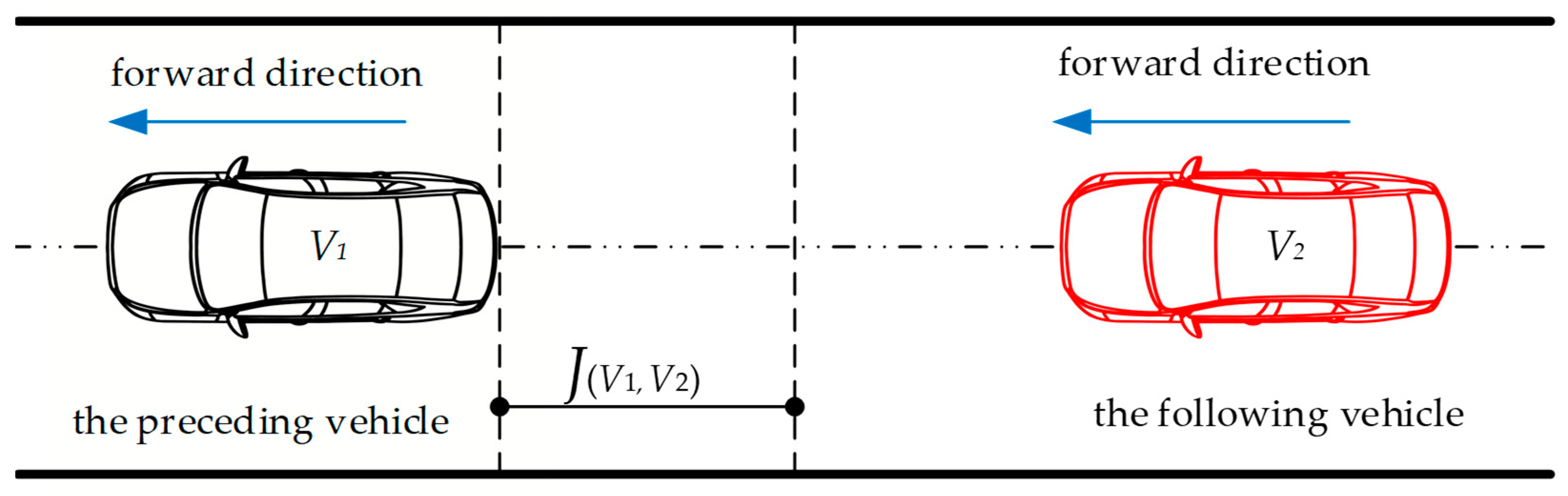
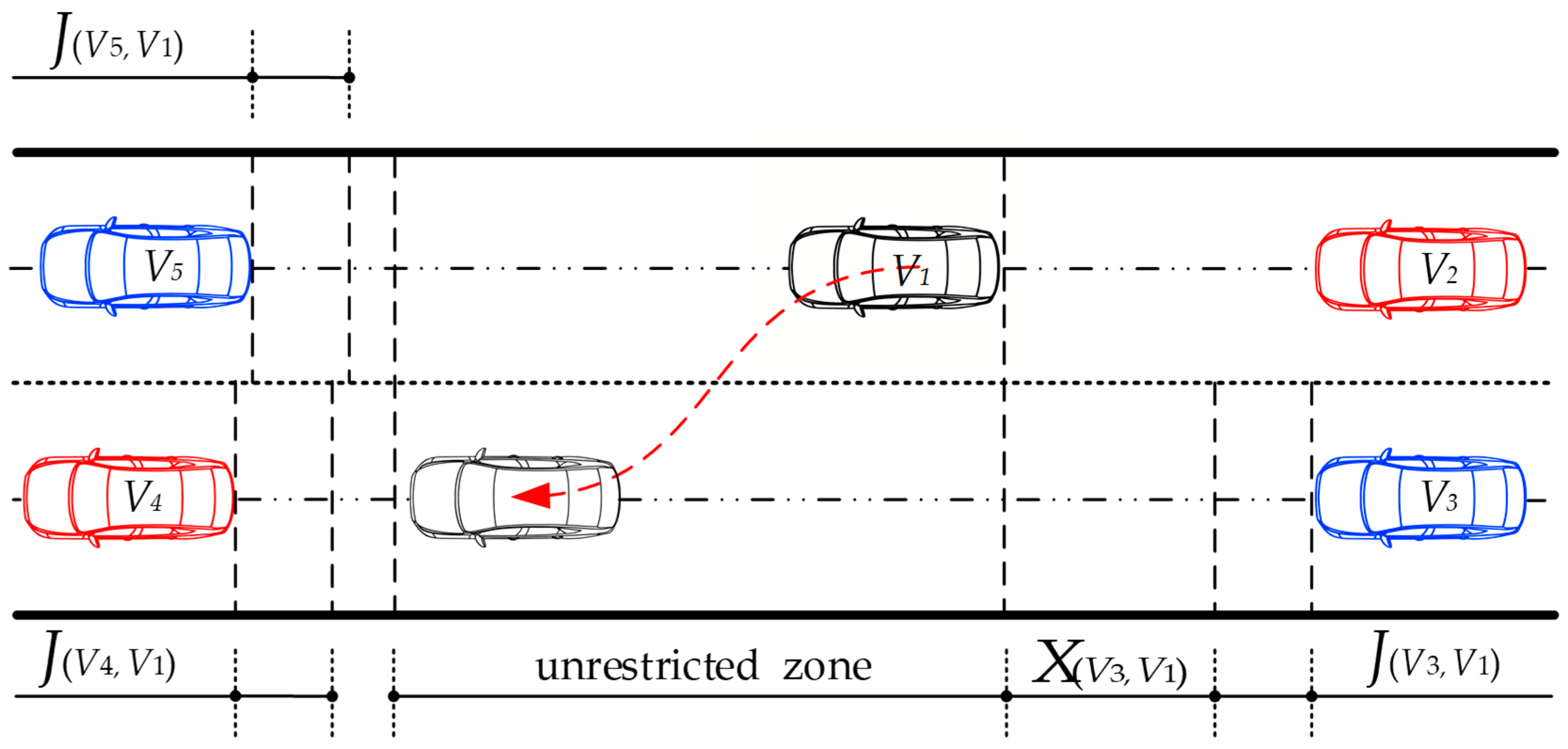
2. The Description of Road Rights in Traffic Scenarios
3. Design of Driving Strategy
3.1. Two Frameworks
- The frameworks are only applicable to lane-changing scenarios in the same direction, and no interference from other traffic participants during AVs driving;
- AVs enable the perception of other vehicles or obstacles, including speed, acceleration, distance, etc.;
- In traffic scenarios, only one vehicle can exist in the same place on a lane.
3.2. Driving Strategy Applied to Transportation Scenarios
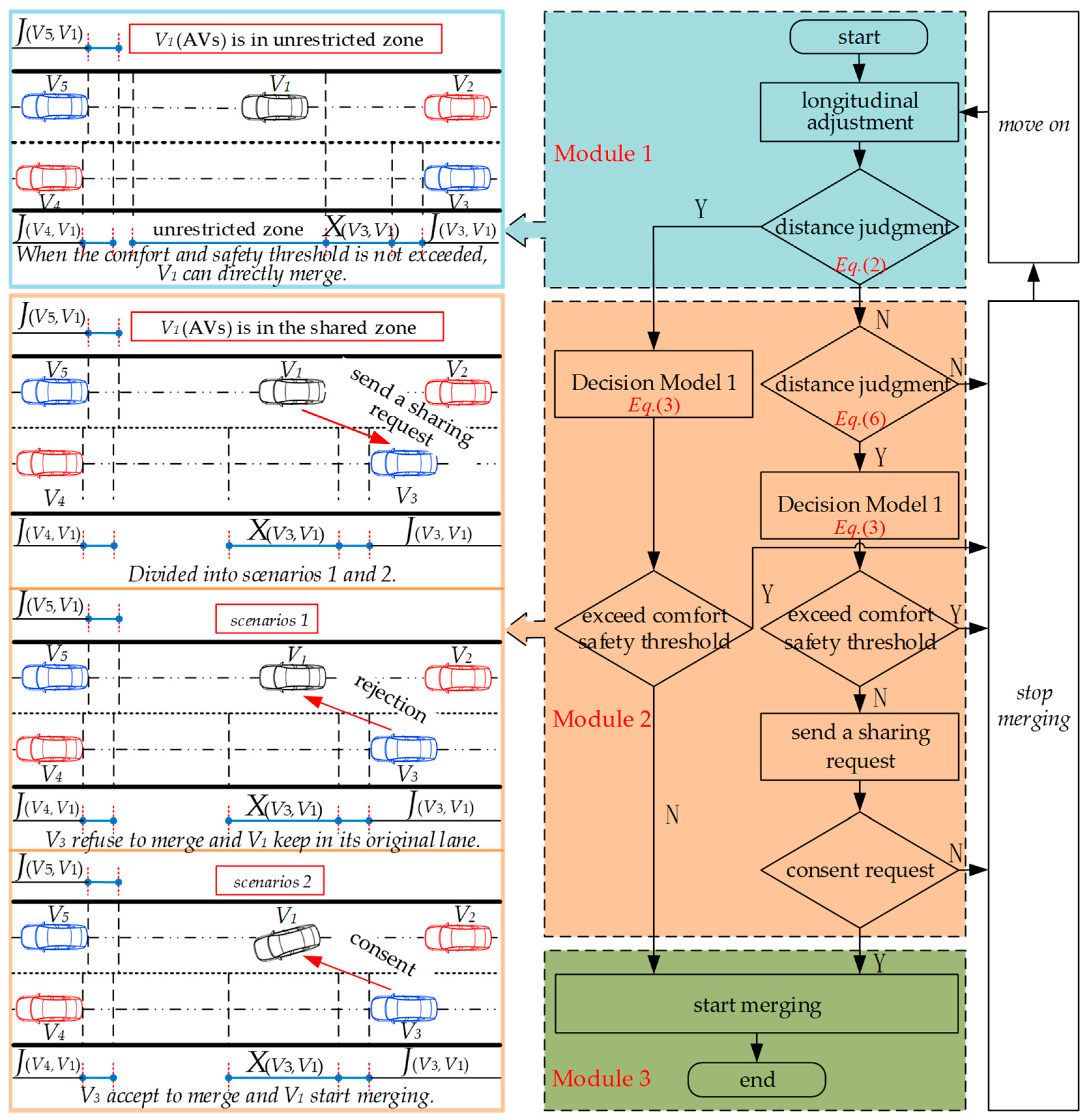
3.2.1. AVs Can Merge Directly without Sending a Sharing Request
- A comfort and safety threshold is previously based on the comfort level;
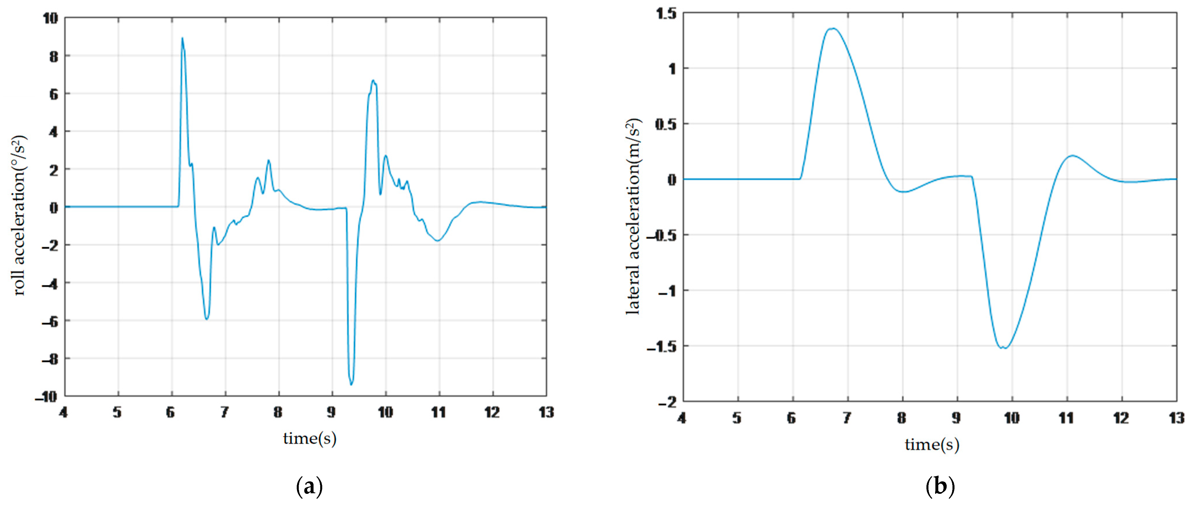
- AVs use the vehicle dynamics model to input the current vehicle speed and distance from the target position to obtain the roll acceleration and lateral acceleration generated during lane changing. It is worth noting that, at this moment, the AVs have not changed lanes;
- AVs use Decision Model 1 to obtain the variance of lane changing by taking roll acceleration and lateral acceleration as inputs. If the variance does not exceed the pre-set comfort and safety threshold, the AVs can change lanes now.
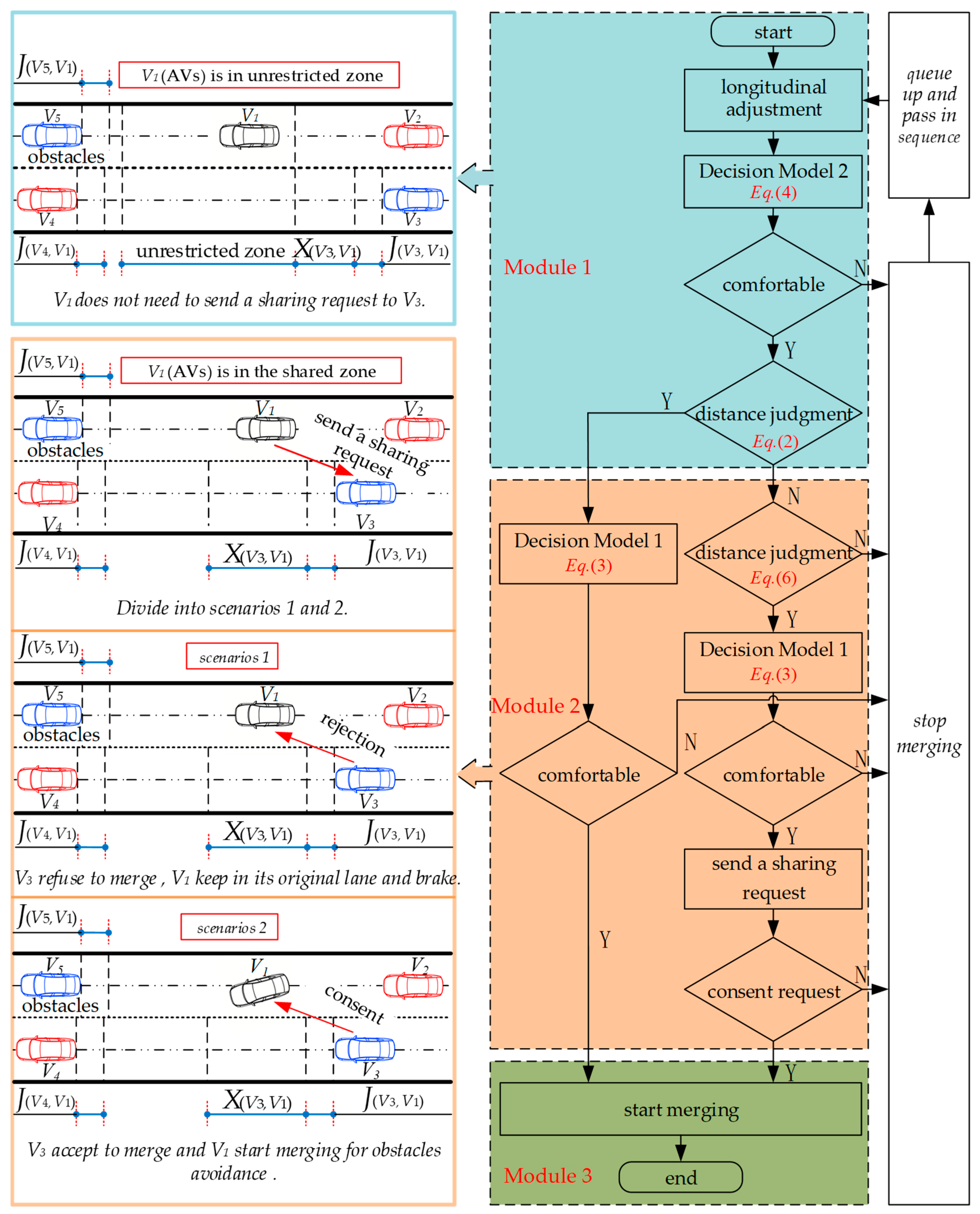
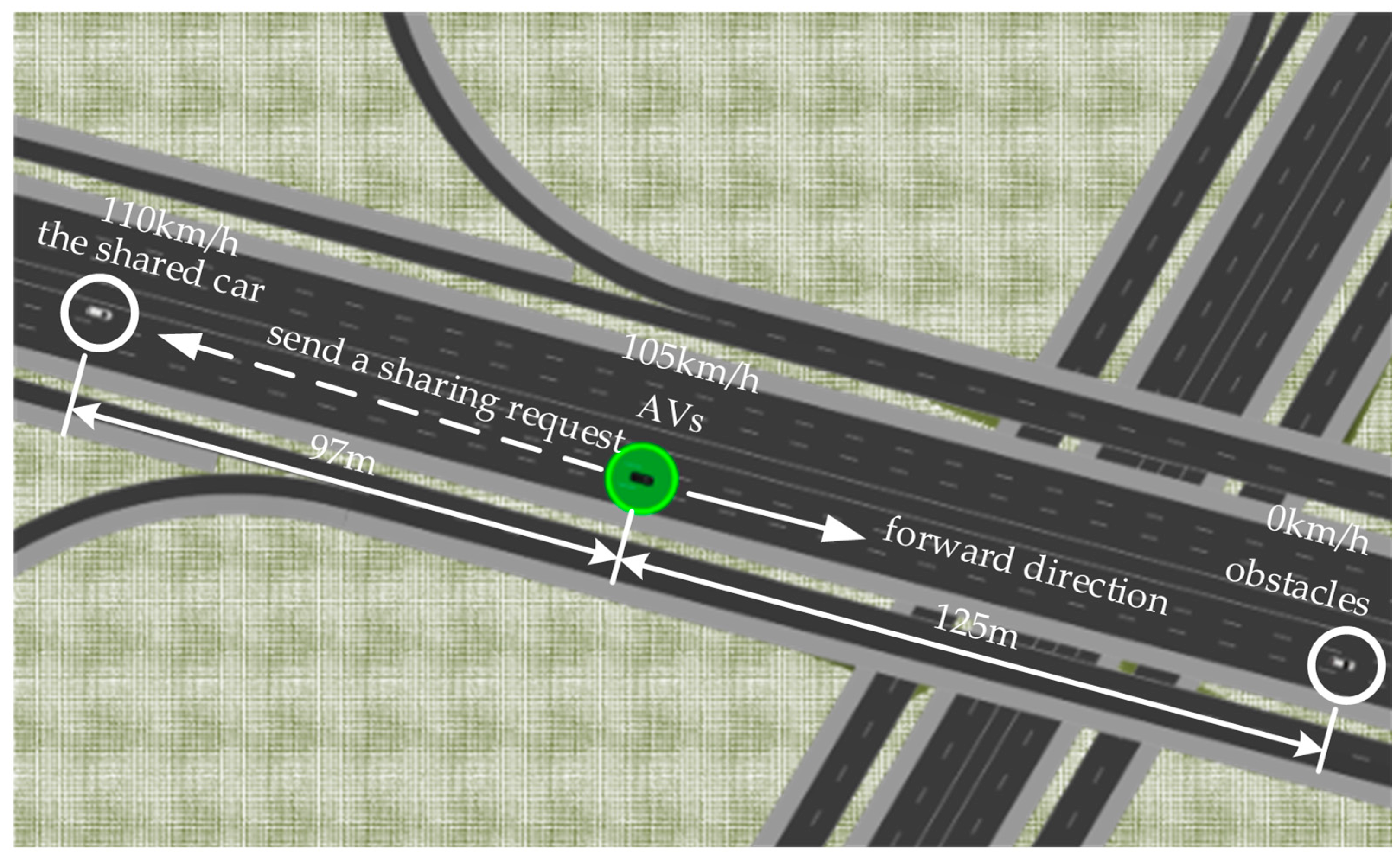
- After identifying obstacles, AVs determine deceleration or steering through Decision Model 2. If AVs want to change lanes to the left and avoid obstacles at this moment, but cannot do so yet, the AVs need to be further evaluated through Decision Model 1;
- AVs use the vehicle dynamics model to input the current vehicle speed and distance from the obstacles to obtain the roll acceleration and lateral acceleration generated during lane changing. AVs obtain the pitch acceleration and longitudinal acceleration generated during braking through Equation (5). It is worth noting that, at this moment, the AVs have not changed lanes or braked;
- AVs obtain the variance of braking and the variance of left lane changing through Decision Model 1, respectively. If the variance of left lane changing to the left is smaller than the variance of braking at this moment, the AVs will perform lane changing to the left to avoid obstacles.
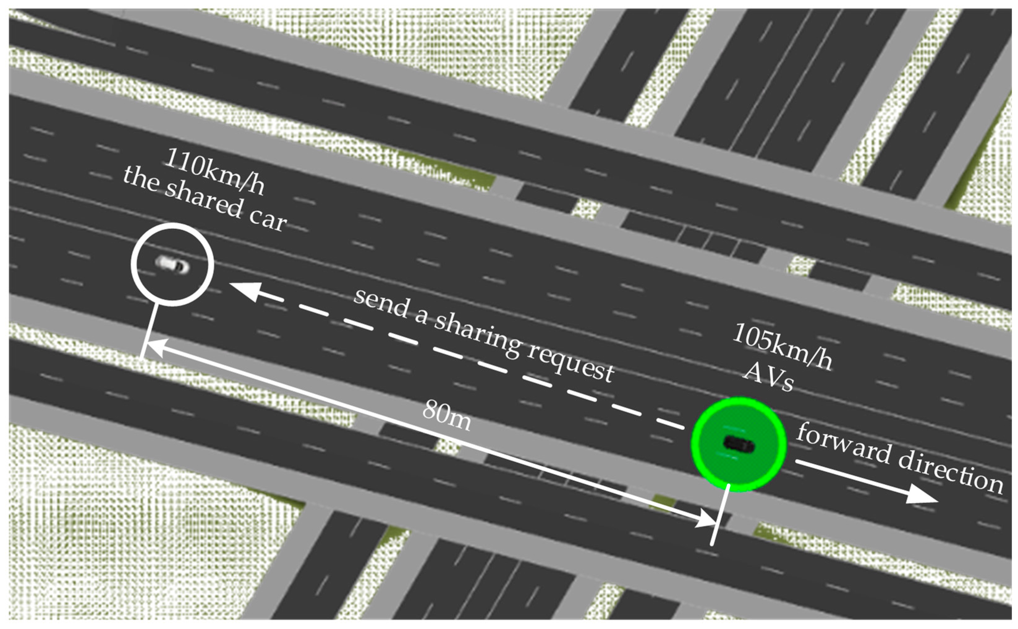
3.2.2. AVs Need to Request Sharing of Merging
- A comfort and safety threshold is preset based on the comfort level;
- AVs use the vehicle dynamics model to input the current vehicle speed and distance from the target position to obtain the roll acceleration and lateral acceleration generated during lane changing. It is worth noting that, at this moment, the AVs have not changed lanes;
- AVs use Decision Model 1 to obtain the variance of lane changing by taking roll acceleration and lateral acceleration as inputs. If the variance does not exceed the pre-set comfort and safety threshold, the AVs can send a sharing request to ;
- When agrees to the request, the AVs begin to perform lane changing. Otherwise, they stop changing lanes.
- After identifying obstacles, AVs determine deceleration or steering through Decision Model 2. If the AVs want to change lanes to the left and avoid obstacles at this moment, but cannot do so yet, the AVs need to be further evaluated through Decision Model 1;
- AVs use the vehicle dynamics model to input the current vehicle speed and distance from the obstacles to obtain the roll acceleration and lateral acceleration generated during lane changing. The AVs obtain the pitch acceleration and longitudinal acceleration generated during braking through Equation (5). It is worth noting that, at this moment, the AVs have not changed lanes or braked;
- AVs obtain the variance of braking and the variance of left lane changing through Decision Model 1, respectively. If the variance of left lane changing is smaller than the variance of braking at this moment, the AVs can send a sharing request to ;
- When agrees to the request, the AVs begin to perform lane changing. Otherwise, they stop changing lanes.
4. Results
4.1. Simulation Verification
4.1.1. AVs Actively Change Lanes
4.1.2. AVs Passively Change Lanes
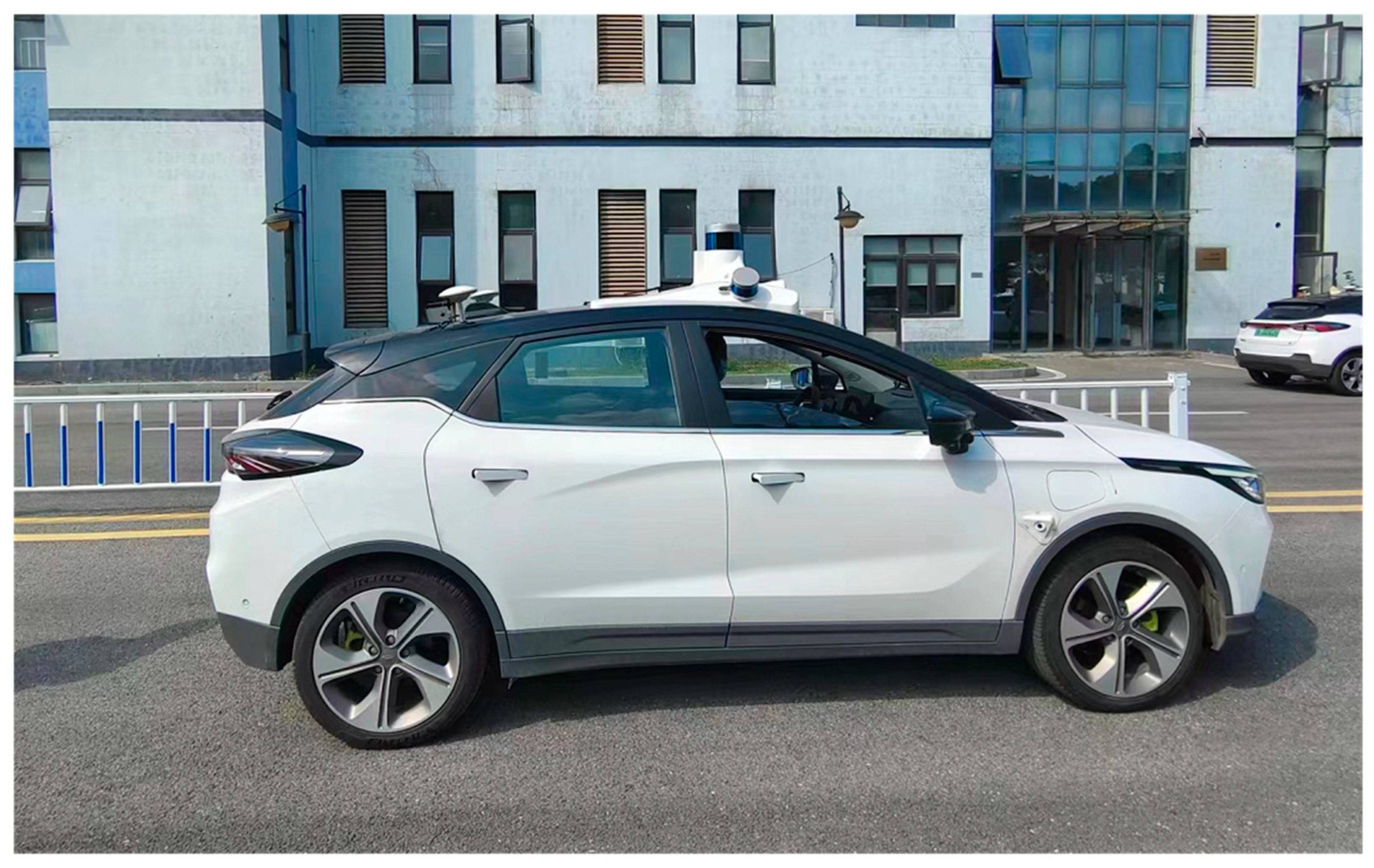
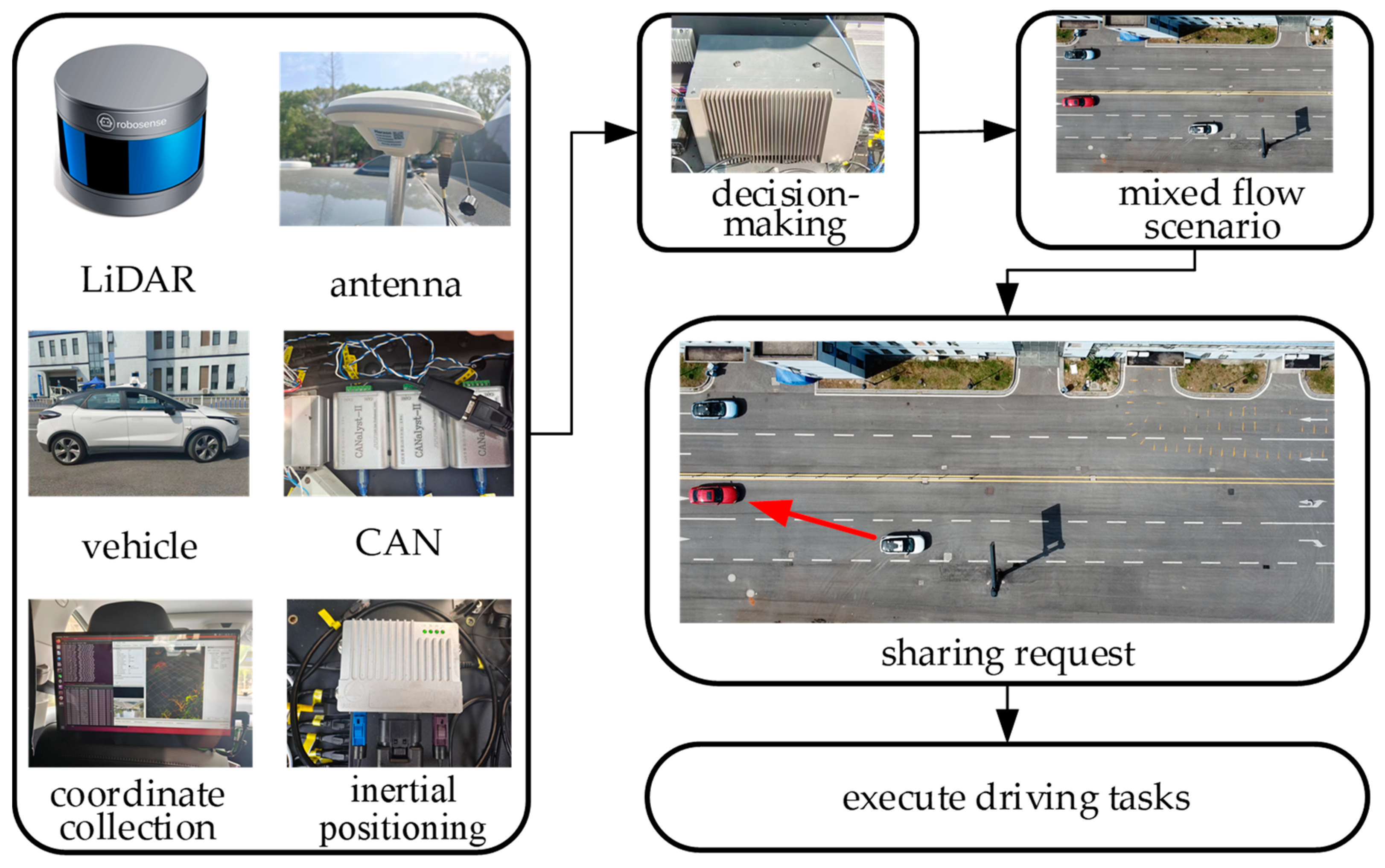
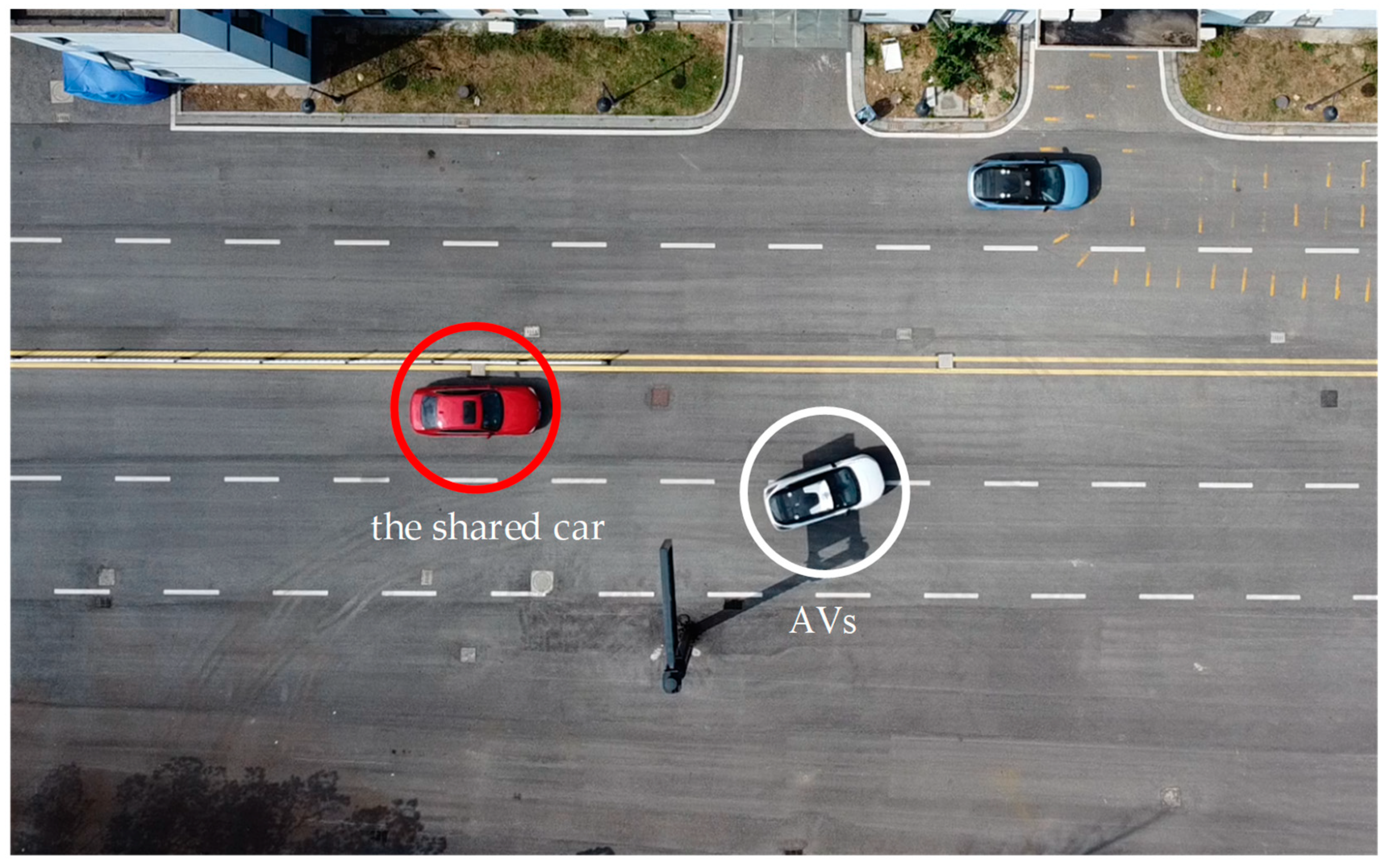
4.2. Real Vehicle Verification
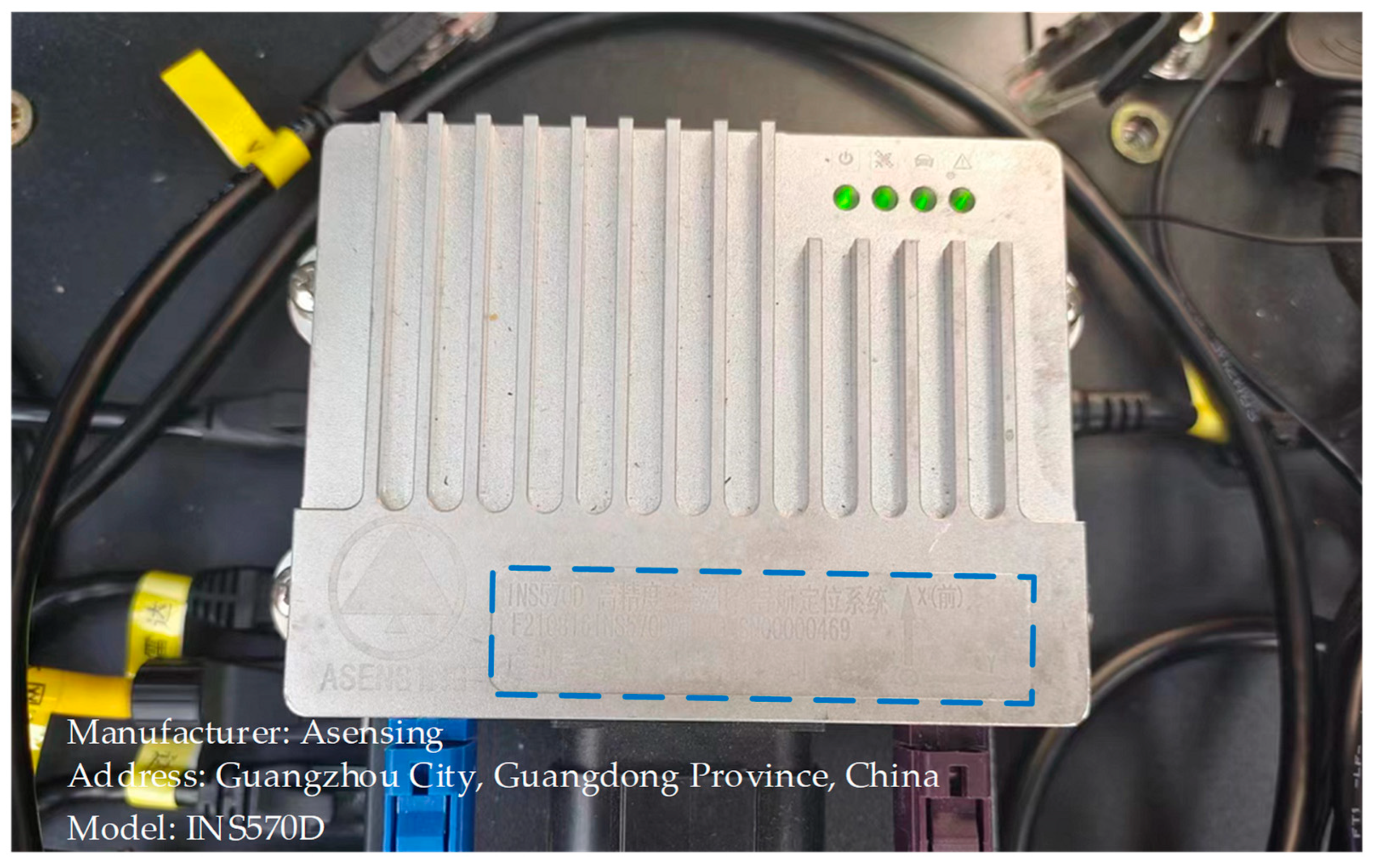
4.2.1. Experimental Platform
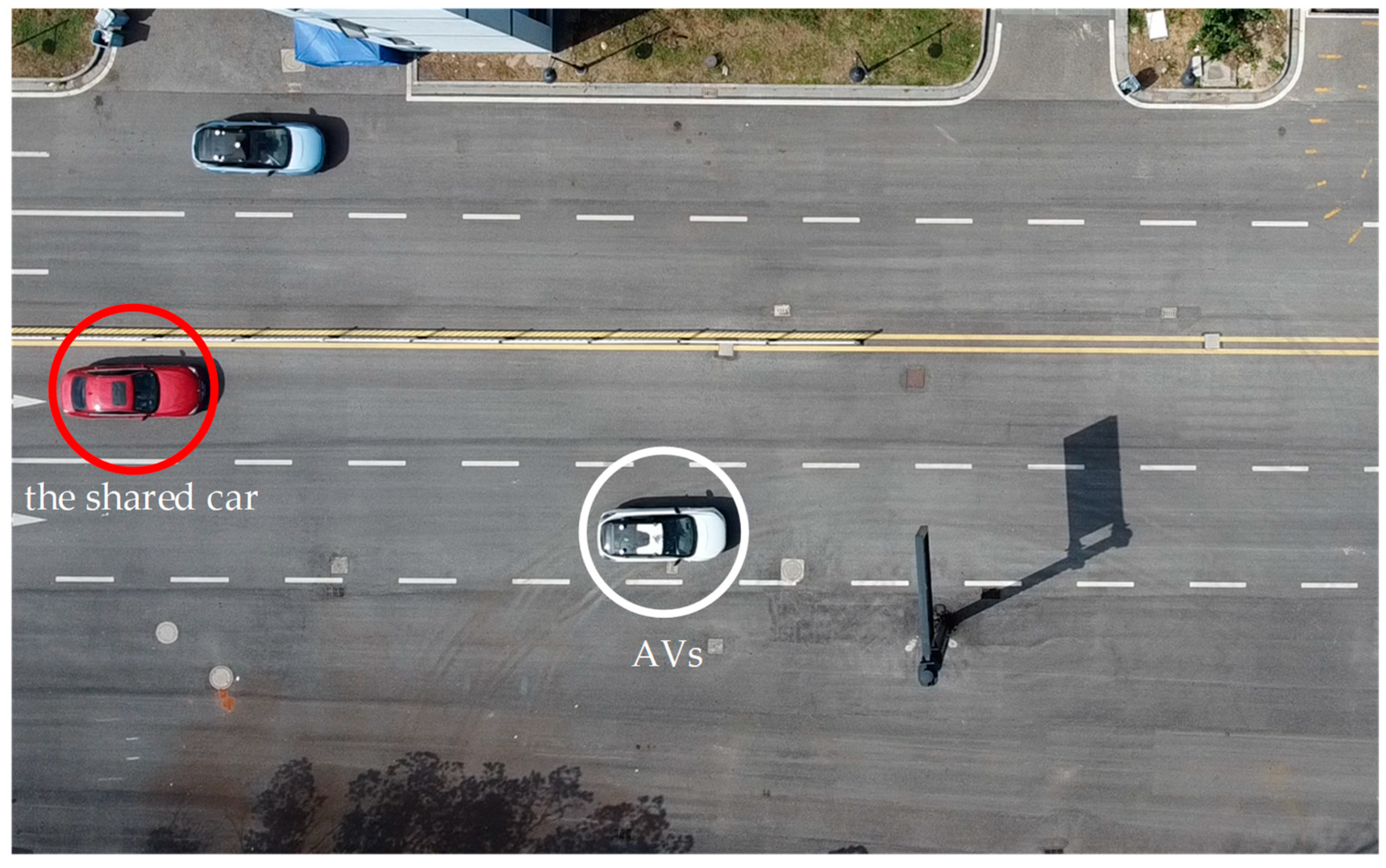
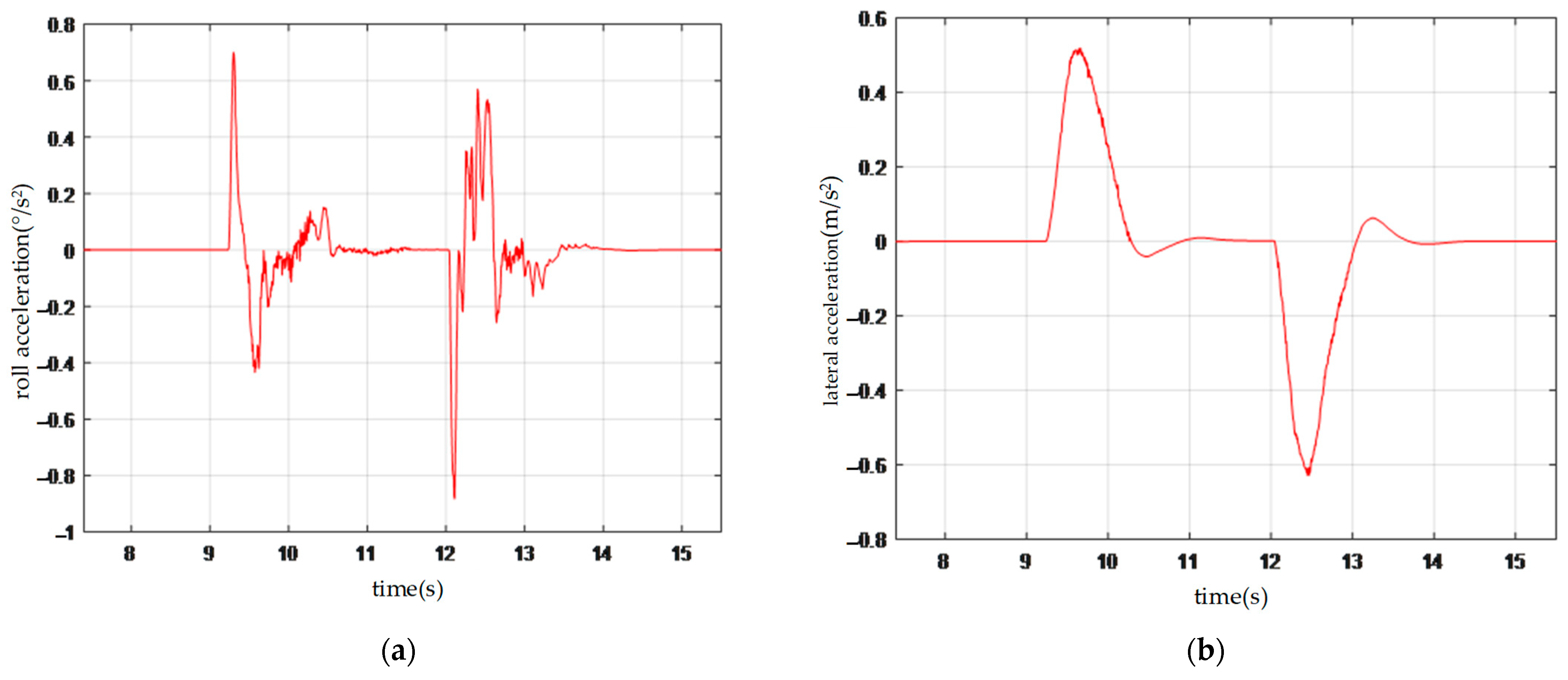
4.2.2. Verification of Feedback Testing
5. Discussion and Conclusions
Author Contributions
Funding
Data Availability Statement
Conflicts of Interest
References
- Zhao, C.; Li, L.; Pei, X.; Li, Z.; Wu, X. A Comparative Study of State-of-the-Art Driving Strategies for Autonomous Vehicles. Accid. Anal. Prev. 2021, 150, 105937. [Google Scholar] [CrossRef]
- Choi, J.H.; Lee, H.J.; Oh, S.; Nam, K. Development of Vehicle Maneuvering System for Autonomous Driving. Mechatronics 2022, 85, 102798. [Google Scholar] [CrossRef]
- Cong, P.; Feng, H.; Li, S.; Li, T.; Xu, Y.; Zhang, X. A Visual Detection Algorithm for Autonomous Driving Road Environment Perception. Eng. Appl. Artif. Intell. 2024, 133, 108034. [Google Scholar] [CrossRef]
- Shalev-Shwartz, S.; Shammah, S.; Shashua, A. On a Formal Model of Safe and Scalable Self-Driving Cars. arXiv 2017, arXiv:1708.06374. [Google Scholar] [CrossRef]
- Liard, T.; Stern, R.; Delle Monache, M.L. Optimal Driving Strategies for Traffic Control with Autonomous Vehicles. IFAC-PapersOnLine 2020, 53, 5322–5329. [Google Scholar] [CrossRef]
- Li, Z.; Zhan, W.; Sun, L.; Chan, C.-Y.; Tomizuka, M. Adaptive Sampling-Based Motion Planning with a Non-Conservatively Defensive Strategy for Autonomous Driving. IFAC-PapersOnLine 2020, 53, 15632–15638. [Google Scholar] [CrossRef]
- Wang, Y.; Yuan, X.; Sun, C. Learning Autonomous Race Driving with Action Mapping Reinforcement Learning. ISA Trans. 2024, 150, 1–14. [Google Scholar] [CrossRef] [PubMed]
- Azam, S.; Munir, F.; Kyrki, V.; Kucner, T.P.; Jeon, M.; Pedrycz, W. Exploring Contextual Representation and Multi-Modality for End-to-End Autonomous Driving. Eng. Appl. Artif. Intell. 2024, 135, 108767. [Google Scholar] [CrossRef]
- Wang, Y.; Zhang, J.; Chen, Y.; Yuan, H.; Wu, C. Automatic Learning-Based Data Optimization Method for Autonomous Driving. Digit. Signal Process. 2024, 148, 104428. [Google Scholar] [CrossRef]
- Li, G.; Yang, Y.; Qu, X.; Cao, D.; Li, K. A Deep Learning Based Image Enhancement Approach for Autonomous Driving at Night. Knowl.-Based Syst. 2021, 213, 106617. [Google Scholar] [CrossRef]
- Lee, D.; Kwon, M. ADAS-RL: Safety Learning Approach for Stable Autonomous Driving. ICT Express 2022, 8, 479–483. [Google Scholar] [CrossRef]
- Hawlader, F.; Robinet, F.; Frank, R. Leveraging the Edge and Cloud for V2X-Based Real-Time Object Detection in Autonomous Driving. Comput. Commun. 2024, 213, 372–381. [Google Scholar] [CrossRef]
- Ding, H.; Pan, H.; Bai, H.; Zheng, X.; Chen, J.; Zhang, W. Driving Strategy of Connected and Autonomous Vehicles Based on Multiple Preceding Vehicles State Estimation in Mixed Vehicular Traffic. Phys. Stat. Mech. Its Appl. 2022, 596, 127154. [Google Scholar] [CrossRef]
- Shi, R.; Yang, S.; Chen, Y.; Wang, R.; Zhang, M.; Lu, J.; Cao, Y. CNN-Transformer for Visual-tactile Fusion Applied in Road Recognition of Autonomous Vehicles. Pattern Recognit. Lett. 2023, 166, 200–208. [Google Scholar] [CrossRef]
- Schitz, D.; Aschemann, H. Path Optimization for Autonomous Driving Using Deep Learning. IFAC-PapersOnLine 2022, 55, 490–496. [Google Scholar] [CrossRef]
- Liu, S.; Bai, Y. Multiple UAVs Collaborative Traffic Monitoring with Intention-Based Communication. Comput. Commun. 2023, 210, 116–129. [Google Scholar] [CrossRef]
- Eyuboglu, M.; Atali, G. A Novel Collaborative Path Planning Algorithm for 3-Wheel Omnidirectional Autonomous Mobile Robot. Robot. Auton. Syst. 2023, 169, 104527. [Google Scholar] [CrossRef]
- Petrillo, A.; Salvi, A.; Santini, S.; Valente, A.S. Adaptive Multi-Agents Synchronization for Collaborative Driving of Autonomous Vehicles with Multiple Communication Delays. Transp. Res. Part C Emerg. Technol. 2018, 86, 372–392. [Google Scholar] [CrossRef]
- Ghorai, P.; Eskandarian, A.; Kim, Y.-K.; Mehr, G. State Estimation and Motion Prediction of Vehicles and Vulnerable Road Users for Cooperative Autonomous Driving: A Survey. IEEE Trans. Intell. Transp. Syst. 2022, 23, 16983–17002. [Google Scholar] [CrossRef]
- Online Longitudinal Trajectory Planning for Connected and Autonomous Vehicles in Mixed Traffic Flow with Deep Reinforcement Learning Approach. J. Intell. Transp. Syst. 2023, 27, 396–410. [CrossRef]
- Peng, B.; Keskin, M.F.; Kulcsár, B.; Wymeersch, H. Connected Autonomous Vehicles for Improving Mixed Traffic Efficiency in Unsignalized Intersections with Deep Reinforcement Learning. Commun. Transp. Res. 2021, 1, 100017. [Google Scholar] [CrossRef]
- Li, Y.; Ma, D.; An, Z.; Wang, Z.; Zhong, Y.; Chen, S.; Feng, C. V2X-Sim: Multi-Agent Collaborative Perception Dataset and Benchmark for Autonomous Driving. IEEE Robot. Autom. Lett. 2022, 7, 10914–10921. [Google Scholar] [CrossRef]
- Sabouni, E.; Cassandras, C.G. Optimal Merging Control of an Autonomous Vehicle in Mixed Traffic: An Optimal Index Policy. IFAC-PapersOnLine 2023, 56, 2353–2358. [Google Scholar] [CrossRef]
- Zhao, C.; Li, Z.; Li, L.; Wu, X.; Wang, F. A Negotiation-based Right-of-way Assignment Strategy to Ensure Traffic Safety and Efficiency in Lane Changes. IET Intell. Transp. Syst. 2021, 15, 1345–1358. [Google Scholar] [CrossRef]
- Kaszas, D.; Roberts, A.C. Comfort with Varying Levels of Human Supervision in Self-Driving Cars: Determining Factors in Europe. Int. J. Transp. Sci. Technol. 2023, 12, 809–821. [Google Scholar] [CrossRef]
- Hou, X.; Gan, M.; Zhang, J.; Zhao, S.; Ji, Y. Vehicle Ride Comfort Optimization in the Post-Braking Phase Using Residual Reinforcement Learning. Adv. Eng. Inform. 2023, 58, 102198. [Google Scholar] [CrossRef]
- Deubel, C.; Ernst, S.; Prokop, G. Objective Evaluation Methods of Vehicle Ride Comfort—A Literature Review. J. Sound Vib. 2023, 548, 117515. [Google Scholar] [CrossRef]
- Han, C.; Han, T.; Ma, T.; Tong, Z.; Wang, S.; Hei, T. End-to-End BIM-Based Optimization for Dual-Objective Road Alignment Design with Driving Safety and Construction Cost Efficiency. Autom. Constr. 2023, 151, 104884. [Google Scholar] [CrossRef]
- De Winkel, K.N.; Irmak, T.; Happee, R.; Shyrokau, B. Standards for Passenger Comfort in Automated Vehicles: Acceleration and Jerk. Appl. Ergon. 2023, 106, 103881. [Google Scholar] [CrossRef] [PubMed]
- McConnell, W.A. Motion Sensitivity as a Guide to Road Design. SAE Trans. 1957, 65, 493–507. [Google Scholar]


| Driving-Strategy Characteristics | Driving Strategy in This Paper | Defensive Driving Strategy | Competitive Driving Strategy | Cooperative Driving Strategy |
|---|---|---|---|---|
| Road-right sharing | Actively allocate road rights and strictly follow the road rights | Less emphasis on road right sharing, conservative driving | Does not prioritize road-right sharing, may lead to conflicts | Involves road-right sharing but relies more on collaborative decision-making |
| Decision optimization | Optimized decision models tailored to different driving scenarios | Decisions based on single safety criteria | Pursues efficiency maximization | Collaborative optimization decisions based on information sharing |
| Safety | Ensure safety through multiple decision-making judgments | High safety but may compromise efficiency | Safety may be compromised due to competition | Collaborative efforts reduce conflicts, improving safety |
| Efficiency and comfort | Balances safety with efficiency, enhancing passenger comfort | Lower efficiency but higher comfort | Higher efficiency may compromise comfort | Collaborative optimization achieves a balance between efficiency and comfort |
| Adaptability | Strong adaptability to complex environments, applicable to high-speed and low-speed scenarios | Strong adaptability to complex environments but conservative strategy | Good adaptability for efficiency gains, but safety needs improvement | Relies on collaborative systems, showing strong adaptability to new environments |
| Research contributions | Provides a new perspective on road right allocation in mixed traffic, advancing autonomous driving technology | Emphasizes safe driving standards | Explores efficient driving strategies | Showcases the potential of cooperative driving, driving intelligent transportation development |
| Style Type | Characteristics | Applicable Scenarios |
|---|---|---|
| Ultimate comfort | Focuses on passenger comfort, avoids abrupt maneuvers, and optimizes suspension, noise reduction, and seating | Long-distance travel, business transfers, and family outings |
| Balanced comfort | Balances comfort with driving pleasure and flexibly adjusts to road conditions | Daily commuting, urban driving, and short trips |
| Sport–aggressive | Emphasizes driving dynamics and speed and provides responsive acceleration, high shift RPMs, and precise steering control | Mountain roads, racetrack experiences, and performance-car demonstrations |
| Intelligent–adaptive | Leverages advanced sensors, algorithms, and AI technology to perceive road conditions, driving contexts, and passenger preferences, automatically adjusts driving style, and predicts and adapts to future driving situations for optimal driving experience and safety | All-terrain, all-weather driving, especially scenarios requiring highly intelligent and personalized driving experiences |
Disclaimer/Publisher’s Note: The statements, opinions and data contained in all publications are solely those of the individual author(s) and contributor(s) and not of MDPI and/or the editor(s). MDPI and/or the editor(s) disclaim responsibility for any injury to people or property resulting from any ideas, methods, instructions or products referred to in the content. |
© 2024 by the authors. Licensee MDPI, Basel, Switzerland. This article is an open access article distributed under the terms and conditions of the Creative Commons Attribution (CC BY) license (https://creativecommons.org/licenses/by/4.0/).
Share and Cite
Li, M.; Li, G.; Sun, C.; Yang, J.; Li, H.; Li, J.; Li, F. A Shared-Road-Rights Driving Strategy Based on Resolution Guidance for Right-of-Way Conflicts. Electronics 2024, 13, 3214. https://doi.org/10.3390/electronics13163214
Li M, Li G, Sun C, Yang J, Li H, Li J, Li F. A Shared-Road-Rights Driving Strategy Based on Resolution Guidance for Right-of-Way Conflicts. Electronics. 2024; 13(16):3214. https://doi.org/10.3390/electronics13163214
Chicago/Turabian StyleLi, Mei, Guisheng Li, Chuan Sun, Junru Yang, Haoran Li, Jialin Li, and Fei Li. 2024. "A Shared-Road-Rights Driving Strategy Based on Resolution Guidance for Right-of-Way Conflicts" Electronics 13, no. 16: 3214. https://doi.org/10.3390/electronics13163214
APA StyleLi, M., Li, G., Sun, C., Yang, J., Li, H., Li, J., & Li, F. (2024). A Shared-Road-Rights Driving Strategy Based on Resolution Guidance for Right-of-Way Conflicts. Electronics, 13(16), 3214. https://doi.org/10.3390/electronics13163214