Article

Sliding Mode Speed Control for PMSM Based on Model Predictive Current

1
College of Automation and Electronic Information, Xiangtan University, Xiangtan 411105, China
2
Department of Electrical Engineering, Tsinghua University, Beijing 100084, China
3
Beijing Institute of Mechanical Equipment, Beijing 100854, China
*
Author to whom correspondence should be addressed.
Electronics 2024, 13(13), 2561; https://doi.org/10.3390/electronics13132561
Submission received: 17 May 2024 / Revised: 22 June 2024 / Accepted: 25 June 2024 / Published: 29 June 2024

Abstract

:
To enhance the dynamic performance and disturbance rejection capability of the permanent magnet synchronous motor speed control system, a novel speed control method based on a novel sliding mode control (NSMC) and load torque observer is proposed on the basis of model predictive current control (MPCC) with a sliding mode disturbance observer. First, on the basis of MPCC, the influence of parameters such as resistance, inductance, and flux linkage on MPCC is analyzed. To address the aggregated disturbance caused by parameter mismatches, a piecewise square-root switching function sliding mode disturbance observer (SMDO) is designed to enhance the robustness of the parameters. To address the poor dynamic performance and inadequate robustness resulting from the proportional-integral-controller (PI) velocity loop control in the MPCC, a novel NSMC velocity control method is proposed. This method utilizes the hyperbolic sine function and fractional-order integral sliding mode surface, resolving the dilemma faced by traditional slide mode controllers (SMC) in balancing fast response and reduced vibration. Additionally, to enhance the system’s disturbance rejection capability, a sliding mode torque observer (SMTO) is designed to continuously update the observed load torque value into the NSMC controller, achieving speed compensation control. Finally, through comparative experiments among the proportional integral controller (PI), SMC, NSMC, and NSMC + SMTO, the results indicate that the proposed NSMC + SMTO exhibits the best speed response, steady-state characteristics, and disturbance rejection capability.

1. Introduction

Permanent magnet synchronous motors are widely used in industrial fields such as aerospace propulsion, robotic arms, robots, and machine tools due to their advantages of simple structure, small size, high efficiency, and excellent performance [1,2,3,4,5]. In recent years, model predictive current control has become a very popular control method in motor drives. Due to its ease of implementation, wide applicability, and ability to achieve multi-objective control, it has become a current research hotspot [6,7].
Model Predictive Current Control directly calculates all possible switching states based on the model of the inverter used in the control system and selects the optimal state based on the principle of minimizing the cost function without the need for traditional modulation techniques. This method simplifies the drive system by directly outputting optimal switching signals to the inverter and eliminating the modulation stage. Model Predictive Current Control (MPCC) is a model-based control algorithm that depends on motor parameters, such as stator current, stator inductance, and permanent magnet flux linkage of the PMSM [8,9,10,11]. However, during motor operation, its parameters may vary due to changes in temperature, thereby affecting the accuracy of the current prediction. Reference [12] proposes a robust Model Predictive Current Control (MPCC) strategy based on observers, which utilizes an extended state observer to estimate disturbances and currents, thereby enhancing the robustness of the system. However, a significant challenge lies in the extensive parameter tuning required. Reference [13] introduces a robust MPCC method based on immune optimization disturbance observers, improving the robustness when motor parameters change. Nevertheless, this method is complex and computationally intensive. To mitigate the impact of parameter mismatch on the performance of MPCC, this paper designs a sliding-mode disturbance observer to observe the aggregated disturbances caused by parameter mismatch, thus reducing the sensitivity of the MPCC strategy to parameter mismatch.
However, in the design of the speed outer loop of MPCC, the current reference value in the cost function is generally obtained using a traditional PI controller. The PI controller not only has a strong dependence on motor parameters but is also very sensitive to changes in load torque. Many advanced control theories have been applied to the control research of PMSM systems to improve the dynamic performance of the speed loop, such as predictive control [14,15,16,17], intelligent control [18,19,20,21,22,23], robust control [24,25,26,27], fuzzy control [28,29], and sliding mode control [30,31,32]. Reference [14] proposes a fault-tolerant finite control set model predictive control method, which reduces the computational burden by synthesizing a virtual voltage vector composed of two basic voltage vectors. This simplifies the control model and improves the steady-state performance of the system. Reference [15] proposes an improved predictive trajectory control strategy to enhance the dynamic performance of PMSM drives. It integrates trajectory optimization with dynamic modulation algorithms, thereby simplifying the computation process, reducing code execution time, and optimizing the transient performance of the control system. Reference [16] introduces Model Predictive Control (MPC), which relies on Performance Control Algorithms (PCA) to achieve high dynamic performance. In the PCA algorithm, MPC calculates the required d-axis current directly using a modified reference speed rather than the original speed. This method effectively reduces speed reduction and torque fluctuations caused by load disturbances. Reference [17] proposes Time-Optimal Model Predictive Control, which incorporates current and torque constraints as time-varying softened state constraints into the continuous control set model predictive flux control. This allows for achieving the estimated flux reference in the shortest time possible without overcurrent, torque overshoot, or undershoot. Reference [18] proposes a genetic algorithm-based simplified speed control for PMSM, employing a direct voltage controller and relying on the motor model for accurate speed tracking. This eliminates the need for current loop regulation, motor parameter knowledge, current, and voltage transducers, thus simplifying the control structure. Reference [20] utilizes an intelligent non-singular terminal sliding mode control recursive Petri probability fuzzy neural network endowed with intelligent non-singular terminal sliding mode control characteristics to construct an intelligent control system. The experimental results demonstrate the effectiveness and robustness of the proposed method. Reference [24] proposes a robust non-singular terminal sliding mode controller that combines a novel non-singular terminal sliding mode function with a super-twisting algorithm. This controller ensures system convergence to equilibrium within a finite time, effectively eliminates chattering phenomena, and enhances system robustness. Reference [26] introduces a robust continuous model predictive control method for the speed and current of permanent magnet synchronous motors based on an adaptive integral sliding mode approach. This strategy addresses chattering issues in sliding mode control and improves system dynamic performance. Reference [28] presents a virtual-reference-based fuzzy non-cascaded speed regulation method for permanent magnet synchronous motors. Experimental results demonstrate a good speed response even under conditions of load torque mismatch, with no occurrence of overcurrent. Reference [30] proposes a novel sliding mode speed controller suitable for the parallel operation of dual permanent magnet synchronous motors with a single inverter. Experimental results demonstrate that with this nonlinear controller, good robust control performance can be achieved even under parameter mismatch conditions between the two motors. Reference [31] introduced an extended state observer using the Fast Terminal Sliding Mode Control (FTSMC) method. This approach enhances the system’s robustness to load disturbances and finite-time convergence, effectively reducing system chattering phenomena. Reference [32] presents a sliding mode control method based on a new sliding mode reaching law, which not only effectively suppresses inherent system chattering but also accelerates the speed of the system state reaching the sliding mode surface. Predictive control can predict future system states and make optimized controls, but it requires high computational power. Intelligent control can adapt to complex nonlinear problems, but parameter tuning is complex. Robust control has good robustness to parameter changes but has performance issues at high precision. Fuzzy control can be applied to complex systems, but designing fuzzy rules is challenging. Sliding mode control has excellent dynamic performance and tremendous potential, along with its strong disturbance rejection capability and low precision requirements for system parameters. It has received extensive research and attention in the field of motor control.
In a motor control system, load variations can impact the performance of the speed control loop. To enhance the system’s ability to withstand load disturbances, a load torque observer can be designed. Reference [33] proposes a load torque identification method based on a sliding mode observer, which features high observation accuracy and fast convergence speed. Reference [34] introduces a variable structure sliding mode observer for load torque observation, with advantages such as high estimation accuracy and elimination of oscillation signals in the identified values. Currently, the application of sliding mode observers is widespread in observing load torque.
To improve the robustness and dynamic performance of the speed outer loop of MPCC, this paper proposes a NSMC method, which resolves the dilemma between achieving rapid response and reducing chattering in traditional SMC methods. Additionally, a segmented square root switching function is proposed to further reduce chattering. Simultaneously, a sliding mode load torque observer is constructed to dynamically observe the load torque and feed it into the NSMC controller, enhancing the control system’s resistance to load disturbances. The experimental results confirm the effectiveness of the proposed novel SMC control method in the speed regulation system of permanent magnet synchronous motors. The main contributions of this paper are as follows:
(1)
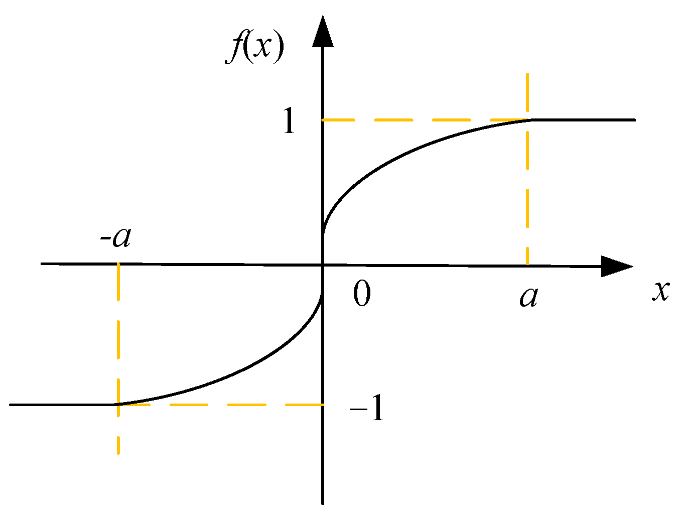
A disturbance observer is designed based on MPCC to improve the parameter robustness of MPCC. Additionally, a novel sliding mode reaching law is designed in the speed loop to reduce system chattering while achieving fast system convergence to the sliding mode surface. The sign function sgn(s) in the reaching law is replaced with a piecewise square root switching function f(x) to further reduce chattering. Simultaneously, a fractional-order integral sliding mode surface is introduced to reduce steady-state errors in the system.
(2)
To enhance the system’s resistance to load disturbances, a sliding mode load torque observer is designed to rapidly and accurately estimate the load torque value, enabling compensation of the output of the novel sliding mode controller. This approach aims to mitigate the effects of sudden changes in velocity on the control system.
The rest of the paper is organized as follows. Section 2 introduces the mathematical models of PMSM and MPCC. Section 3 designs the MPCC with a sliding mode disturbance observer. Section 4 presents the design of a novel sliding mode speed controller. Section 5 conducts an experimental comparative analysis. Section 6 concludes this paper.

2. PMSM Model Predictive Current Control

2.1. Mathematical Model of PMSM

The current equations of the permanent magnet synchronous motor in the d-q coordinate system can be represented as [35,36,37].
{ d i d d t = 1 L d ( u d R i d + ω e L q i q ) d i q d t = 1 L q ( u q R i q ω e L d i d ω e ψ f )
where id, iq, ud, uq represent the stator current and stator voltage in the d-q coordinate system, respectively; R, Ld, Lq represent the stator resistance, d-axis, and q-axis stator inductance, respectively; ωe is the electrical angular speed of the rotor; ψf is the magnetic flux generated by the permanent magnet. Where id and iq are measured in amperes (A), ud and uq are measured in volts (V), R is measured in ohms (Ω), Ld and Lq are measured in henries (H), ωe is measured in radians per second (rad/s), and ψf is measured in webers (Wb).
The electromagnetic torque equation and mechanical motion equation of PMSM are [38]:
T e = 3 2 n p ψ f i q = K t i q
J d ω m d t = T e T L B m ω m
where np represents the number of magnetic poles; Kt is the torque constant; J is the moment of inertia of the rotor; ωm is the mechanical angular velocity of the rotor, which relates to the electrical angular velocity ωe of the rotor as: ωe = npωm; TL is the load torque; Bm is the viscous friction coefficient, which is very small and can be neglected in most cases. The unit of Te is Newton-meters (N·m), the unit of Kt is Newton-meters per ampere (N·m/A), the unit of J is kilograms square meters (kg·m2), ωm is measured in radians per second (rad/s), TL is measured in Newton-meters (N·m), and Bm is measured in Newton-meters per radians per second (N·m/rad/s).

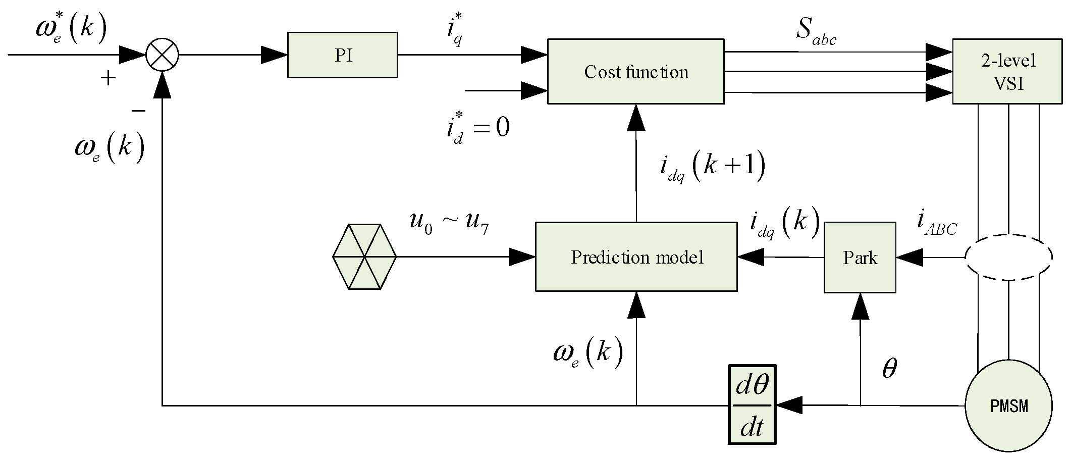
2.2. Model Predictive Current Control

Applying forward Euler discretization to Equation (1), we can obtain the predictive current model as:
{ i d ( k + 1 ) = ( 1 T s R L d ) i d ( k ) + T s L d u d ( k ) + L q L d T s ω e ( k ) i q ( k ) i q ( k + 1 ) = ( 1 T s R L q ) i q ( k ) + T s L q u q ( k ) L d L q T s ω e ( k ) i d ( k ) T s ψ f L q ω e ( k )
where id(k + 1) and iq(k + 1) are the d-axis and q-axis stator current components at time step (k + 1); id(k) and iq(k) are the d-axis and q-axis stator current components at time step k; Ts is the system control period; ud(k) and uq(k) are the d-axis and q-axis voltage components at time step k.
The paper adopts a two-level voltage source inverter, which has 8 fundamental voltage vectors. The principle of Model Predictive Current Control (MPCC) is to input these 8 sets of voltage vectors into the discrete current equations of the permanent magnet synchronous motor, obtaining 8 sets of predicted currents. Subsequently, these 8 sets of predicted currents are input into the cost function, and the set with the smallest cost function is selected. The corresponding switching states of the inverter are then applied based on this selected set of voltage vectors. The principle block diagram of the MPCC is illustrated in Figure 1, where the cost function is given by:
J = [ i d * i d ( k + 1 ) ] 2 + [ i q * i q ( k + 1 ) ] 2
where i d * and i q * are the reference values for the d-axis and q-axis, respectively.

3. MPCC with Sliding Mode Disturbance Observer

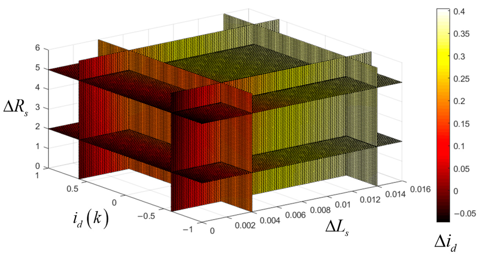
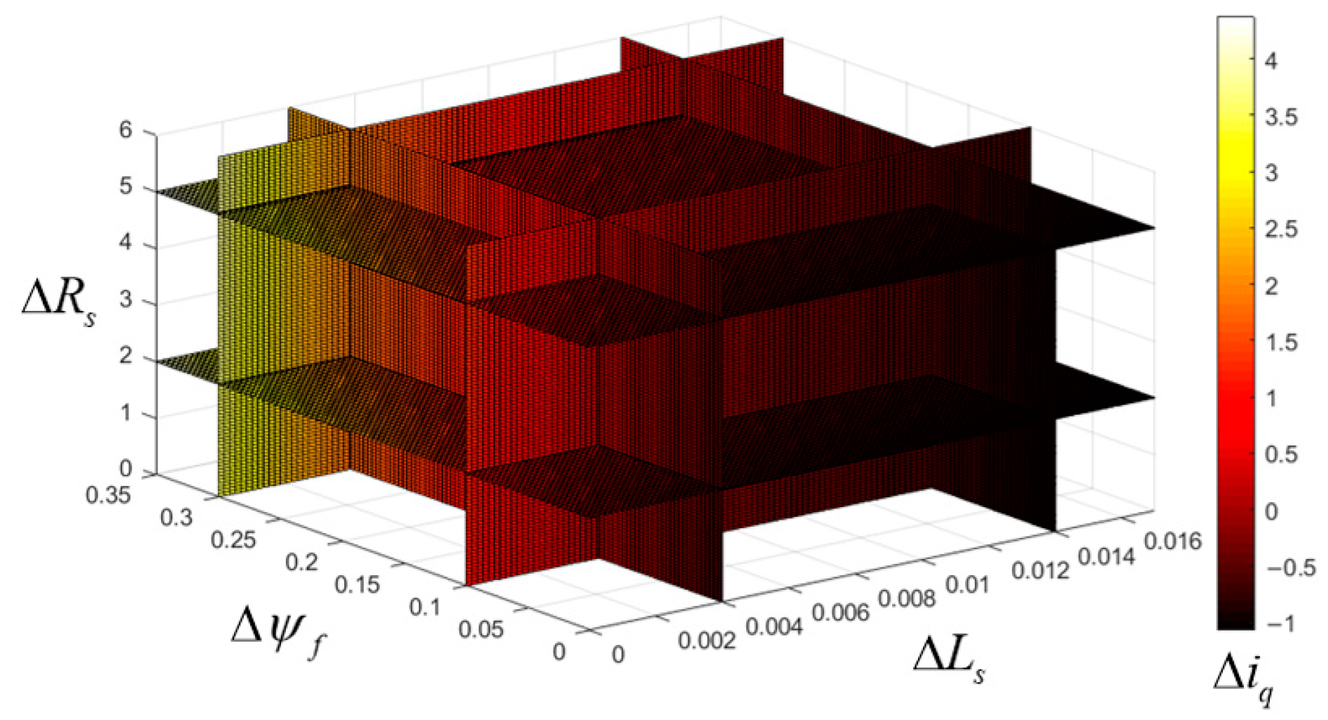
3.1. Parameter Sensitivity of MPCC

During motor operation, any errors in the motor parameters lead to inaccurate current predictions. These inaccurate current predictions will directly result in the selection of incorrect voltage vectors, thereby reducing the control performance of the MPCC method.
According to the current prediction Formula (4), when parameter errors exist, the expression for the current prediction is:
{ i ¯ d ( k + 1 ) = ( 1 T s ( R + Δ R ) L d + Δ L d ) i d ( k ) + T s L d + Δ L d u d ( k ) + L q L d T s ω e ( k ) i q ( k ) i ¯ q ( k + 1 ) = ( 1 T s ( R + Δ R ) L q + Δ L q ) i q ( k ) + T s L q + Δ L q u q ( k ) L d L q T s ω e ( k ) i d ( k ) T s ( ψ f + Δ ψ f ) L q + Δ L q ω e ( k )
where i ¯ d ( k + 1 ) and i ¯ q ( k + 1 ) are the predicted currents of the d-axis and q-axis, respectively, when parameter errors exist; Δ R = R 0 R , Δ L d = L d 0 L d , Δ L q = L q 0 L q , Δ ψ f = ψ f 0 ψ f ; Δ R , Δ L s , and Δ ψ f are the errors between the actual values and the reference values, and R 0 , L d 0 , L q 0 , and ψ f 0 are the actual values of the stator resistance, stator dq-axis inductance, and stator magnetic flux.
Taking the difference between Equations (4) and (6), we obtain the prediction errors of the d-axis and q-axis currents of the motor as:
{ Δ i d = T s L d ( L d + Δ L d ) [ u d ( k ) Δ L d + i d ( k ) ( R Δ L d + Δ R L d ) ] Δ i q = T s L q ( L q + Δ L q ) { Δ L q [ u q ( k ) i q ( k ) R ω e ψ f ] + L q [ i q ( k ) Δ R + ω e Δ ψ f ] }
To analyze the specific impact of parameter errors on the predicted currents, this paper presents a four-dimensional plot illustrating the relationship between parameter errors and predicted current errors under steady-state operation, as shown in Figure 2 and Figure 3.
As per Equation (7), the prediction error of the d-axis current is unaffected by the permanent magnet flux. Figure 2 illustrates the influence of different parameter errors on the predicted d-axis current at a speed of 1000 r/min. The prediction error of the d-axis current is significantly affected by the stator inductance but minimally affected by the stator resistance. Figure 3 depicts the influence of different parameter errors on the predicted q-axis current at a speed of 1000 r/min. It can be observed from Figure 3 that the prediction error of the q-axis current is greatly influenced by the magnetic flux, moderately influenced by the stator inductance, and minimally influenced by the stator resistance.
Clearly, the parameter mismatch has a significant impact on the predicted currents. Therefore, it is necessary to design an observer capable of detecting the errors generated by motor parameters and implementing real-time system compensation to enhance system robustness.

3.2. The Design of SMDO

The sliding mode observer possesses advantages, such as simplicity, ease of implementation, and robustness. Therefore, designing a SMDO to observe aggregated disturbances and compensate them into the predictive model is proposed. Moreover, it employs a piecewise square-root function instead of the sign function in the reaching law to suppress sliding mode chattering.
According to the sliding mode control theory, the linear sliding surface constructed based on the current estimation error is chosen as follows:
{ s d = σ d ( i ^ d i d ) s q = σ q ( i ^ q i q )
where σ d and σ q are the sliding mode chattering suppression factors, and i ^ d and i ^ q represent the estimated values of the d-axis and q-axis currents, respectively. The units for i ^ d and i ^ q are amperes (A).
When motor parameter mismatches exist and the influence of total disturbances is considered, the stator current equation derived from Equation (1) can be expressed as follows [39]:
{ d i d d t = 1 L d ( u d R i d + ω e L q i q f d ) f d = Δ R i d + Δ L d d i d d t ω e Δ L q i q d i q d t = 1 L q ( u q R i q ω e L d i d ω e ψ f f q ) f q = Δ R i q + Δ L q d i q d t + ω e Δ L d i d + ω e Δ ψ f
where fd and fq represent the aggregated disturbances along the d-axis and q-axis, respectively.
Due to the short sampling period, the motor model considering aggregated disturbances can be represented as follows [39]:
{ d i d d t = 1 L d ( u d R i d + ω e L q i q f d ) d f d d t = 0 d i q d t = 1 L q ( u q R i q ω e L d i d ω e ψ f f q ) d f q d t = 0
Based on Equation (10), the SMDO can be designed as follows [40]:
{ d i ^ d d t = 1 L d ( u d R i ^ d + ω e L q i ^ q f ^ d ) + U d d f ^ d d t = g d U d d i ^ q d t = 1 L q ( u q R i ^ q ω e L d i ^ d ω e ψ f f ^ q ) + U q d f ^ q d t = g q U q
where f ^ d and f ^ q represent the observed quantities of disturbance estimates; coefficients g d and g q denote the sliding mode gain factors; U d and U d are switch signals composed of d-axis and q-axis sliding mode reaching laws, respectively.
{ U d = a 1 f ( s d ) U q = a 2 f ( s q )
where a 1 and a 2 are the sliding mode gains, and f(x) is the piecewise square-root switching function, as illustrated in Figure 4, with the formula:
f ( x ) = { 1 x a x a 0 x a x a a x 0   1 x a
where x represents the output of the sliding surface function, and a stands for the boundary layer thickness, which serves as the dividing line for altering the characteristics of the sliding surface function. A larger value of a will decrease chattering effects but may lead to a reduction in control accuracy. Hence, when selecting a, it is necessary to consider a balance between chattering suppression effectiveness and control accuracy.

4. The Novel Sliding Mode Speed Controller

4.1. The Design of the NSMC Controller

SMC is a nonlinear control method that guides the system state trajectories to a specific sliding surface using phase plane control to achieve system stability, a process known as the sliding mode. When SMC is applied in PMSM speed control systems, the state variables x1 and x2 can be designed as follows:
{ x 1 = ω m * ω m x 2 = x ˙ 1 = ω ˙ m
where ω m * represents the desired mechanical angular velocity. ω m represents the actual mechanical angular velocity of the motor.
Combining Equations (2), (3), and (14), it can be concluded that:
{ x ˙ 1 = ω ˙ m = 1 J ( T L K t i q ) x ˙ 2 = ω ¨ m = K t J i ˙ q
Assuming b = 1 J K t and M = i ˙ q , x ˙ 1 and x ¨ 1 represent the derivatives of the state variables x1 and x2, while ω ˙ m and ω ¨ m represent the first and second derivatives of ω m . The state-space equation of the system can be obtained as follows:
[ x ˙ 1 x ˙ 2 ] = [ 0       1 0       0 ] [ x 1 x 2 ] + [ 0 b ] M
The integral sliding surface is selected as:
s = x 1 + c 0 t x 1 d t
where s represents the sliding surface, and c is the integral constant.
We selected the exponential reaching law as the typical reaching law for controlling the trajectory of the state variables:
s ˙ = α sgn ( s ) β s   ,   α > 0   ,   β > 0
where α is the switching gain, and β is the exponential coefficient.
According to Equations (15), (17), and (18), the control law for the SMC controller can be obtained as follows:
i q * = J K t ( c x 1 + α sgn ( s ) + β s ) + 1 K t T L
Equation (19) represents the SMC method used in the subsequent experiments. For traditional SMC methods, the values of α and β in Equation (19) directly affect the dynamic performance of the system. Integrating Equation (18) from 0 to the arrival time t and setting s ( t ) = 0 , the arrival time t can be calculated as:
t = | s ( 0 ) | | 0 t α s d t | β
From Equation (20), it can be observed that to achieve a fast response speed of the controller, it is necessary to reduce the arrival time, which requires higher values of α and β to be designed. However, according to the characteristics of SMC, excessively high values of α and β will significantly exacerbate the chattering phenomenon. Therefore, designing a new exponential approaching law to maintain the fast response speed of the controller while minimizing the system’s vibration amplitude achieves an optimal control effect.
A NSMC is proposed to address the dilemma between reducing chattering and achieving fast dynamic response. The design of the new reaching law is as follows:
s ˙ = α arcsin ( γ | x 1 | ) f ( s ) β s
where arcsin(h) represents the inverse hyperbolic sine function, and the value of γ is greater than 0.
From the characteristics of the inverse hyperbolic sine function, it is evident that its value decreases as the argument decreases, with a smaller argument leading to a smaller slope. Equation (21) indicates that when the state variable x1 moves away from the sliding surface, the reaching speed is high. As the state variable gradually approaches the sliding surface, the reaching speed decreases gradually and eventually approaches zero. Therefore, NSMC can ensure both fast controller response and chattering suppression. Employing a piecewise square root switching function f(x) to replace the sign function sgn(s) in Equation (18) further reduces chattering and enhances the system’s dynamic quality.
When applying the traditional integral sliding surface, the integral term of the velocity error adopts first-order integer integration, which possesses global characteristics. However, when facing significant initial errors or actuator saturation, integral saturation effects may occur, leading to deterioration in the system’s transient performance or even instability. To address this issue, a fractional-order integral sliding surface is designed as follows:
s = x 1 + c D u x 1
where s is the sliding surface; c is the constant of the fractional-order integral; D−ux1 represents the fractional-order integral of the state variable x1, aimed at eliminating the system’s steady-state error; and 0 < u < 1 denotes the order of the fractional-order integral sliding surface.
According to Equations (15), (21) and (22), the reference current i q * of NSMC is determined as follows:
i q * = J K t ( c D 1 u x 1 + α arcsin ( γ | x 1 | ) f ( s ) + β s ) + 1 K t T L
To validate the stability of the improved reaching law, the Lyapunov function is chosen as follows:
V = 1 2 s 2
Taking the derivative of Equation (24), we obtain:
V ˙ = s s ˙
Substituting Equations (15) and (17) into Equation (25), we obtain:
V ˙ = s [ 1 J K t i q + 1 J T L + c D 1 u x 1 ]
By employing the NSMC control law given in Equation (25), we obtain:
V ˙ = s [ 1 J K t ( J K t ( c D 1 u x 1 + α arcsin ( γ | x 1 | ) f ( s ) + β s ) + 1 K t T L ) + 1 J T L + c D 1 u x 1 ] = s [ α arcsin ( γ | x 1 | ) f ( s ) β s ]
From Equation (27), it can be observed that when both parameters α and β are greater than 0, then V ˙ = s s ˙ < 0 , according to the Lyapunov stability theorem, it is evident that the NSMC controller designed based on the improved reaching law is asymptotically stable, ensuring the system reaches the sliding surface.

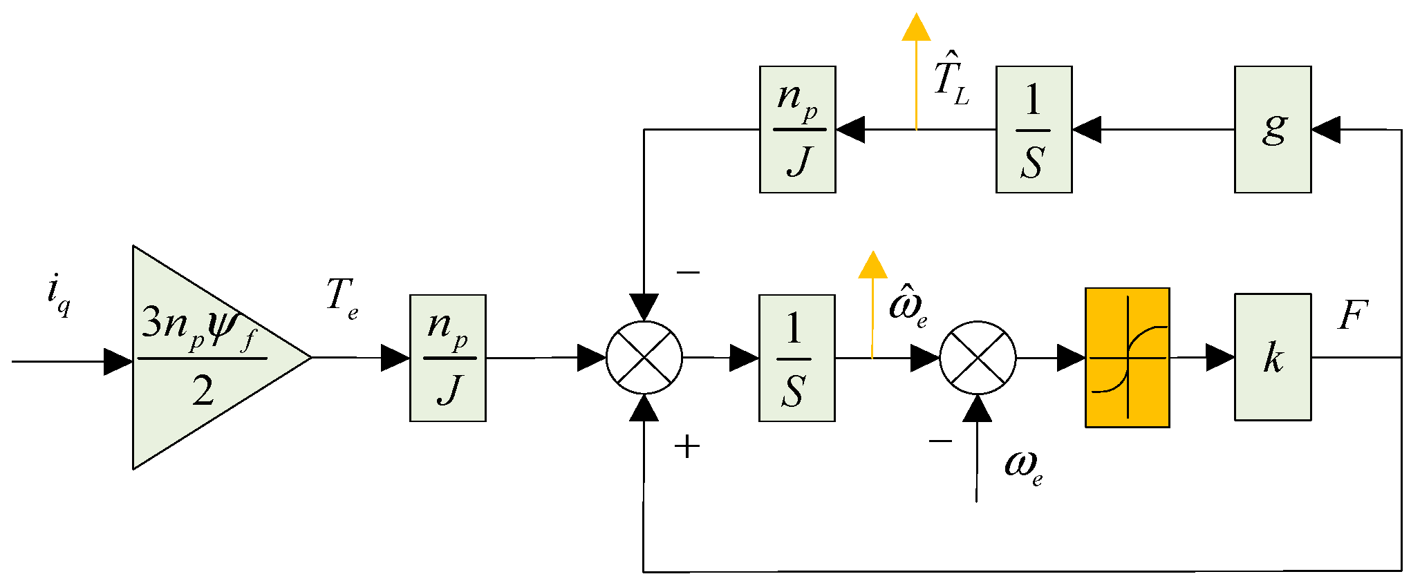
4.2. Design of the Sliding Mode Torque Observer

During the operation of a PMSM, it is challenging to directly measure the load torque value, and adding torque measurement equipment also increases the volume of the motor. To ensure good response performance in the presence of significant external disturbances, it is necessary to design a load torque observer for online observation, thereby enhancing the system’s ability to resist load disturbances.
The error between the estimated electrical angular velocity and the actual electrical angular velocity is first chosen as the sliding surface:
s = ω ^ e ω e
Next, this paper adopts a switching function of constant approaching law, and replaces the sign function sgn(s) in the constant approaching law with a piecewise square root switching function f(x) to further improve the system’s dynamic performance. The expression of the approaching law is as follows:
F = k f ( s )
where k is the parameter of the switching function.
According to the mechanical motion Equation (3), with the load torque as the extended variable, the sliding mode torque observer (SMTO) can be constructed as follows:
{ d ω ^ e d t = n P ( T e T ^ L ) J + F d T ^ L d t = g F
where g represents the sliding mode parameter, and T ^ L represents the observed value of the load torque.
A schematic diagram of the SMTO is shown in Figure 5. The q-axis current value and the actual electrical angular velocity value serve as inputs to the observer, while the outputs are the estimated load torque value and speed.
To ensure the system rapidly and accurately reaches the sliding mode surface, it is necessary to design reasonable observer parameters k and g. The error equations for speed and load torque are defined as follows:
{ s 1 = ω ^ e ω e s 2 = T ^ L T L
The sampling frequency of the controller is much higher than the variation time of the load torque, so the load torque within the control period can be considered constant. That is:
d T L d t = 0
The error differential equation can be obtained from Equations (30)–(32) as follows:
{ d s 1 d t = n p s 2 J + F d s 2 d t = g F
To ensure the stability of the SMTO, inequality s s ˙ 0 must be satisfied, i.e., it must fulfill:
s s ˙ = s d s d t = s 1 d s 1 d t = s 1 [ n p s 2 J + k f ( s ) ] 0
According to Equation (34), the range of values for k can be obtained as follows:
k | n p s 2 J |
Therefore, selecting the appropriate observer parameters k can ensure that the system reaches and stays on the sliding mode surface within a finite time. Thus, the sliding mode surface s and its derivative satisfy:
{ s = d s d t = 0 s 1 = d s 1 d t = 0
Using Equations (33) and (36), we can obtain:
d s 2 d t g n p s 2 J = 0
To ensure that the error in load torque converges to 0, parameter g should be taken as a value less than 0.

4.3. The Principle of Load Disturbance Compensation in PMSM

The paper proposes a system control diagram for a sliding mode speed control method based on model predictive current control for PMSM, as shown in Figure 6. The PMSM control system adopts a dual-closed-loop control strategy for current and speed. The speed and position signals are obtained from the feedback of an optical encoder. The speed loop adopts a sliding mode controller, where the input is the speed error and the output is the desired current value. Space vector modulation with id = 0 is employed, and the current loop adopts model predictive current control considering aggregated disturbances. The observed load torque is fed back to the speed control loop to adjust and update the parameters of the sliding mode control law. Finally, Equation (23) can be rewritten as:
i q * = J K t ( c D 1 u x 1 + α arcsin ( γ | x 1 | ) f ( s ) + β s ) + 1 K t T ^ L
The current predictive model based on aggregated disturbances considering delay compensation is given by:
{ i d ( k + 2 ) = ( 1 T s R L d ) i d ( k + 1 ) + T s ω e ( k + 1 ) i q ( k + 1 ) + T s L d ( u d ( k + 1 ) f ^ d ) i q ( k + 2 ) = ( 1 T s R L q ) i q ( k + 1 ) T s ω e ( k + 1 ) i d ( k + 1 ) + T s L q ( u q ( k + 1 ) ψ f ω e ( k + 1 ) f ^ q )

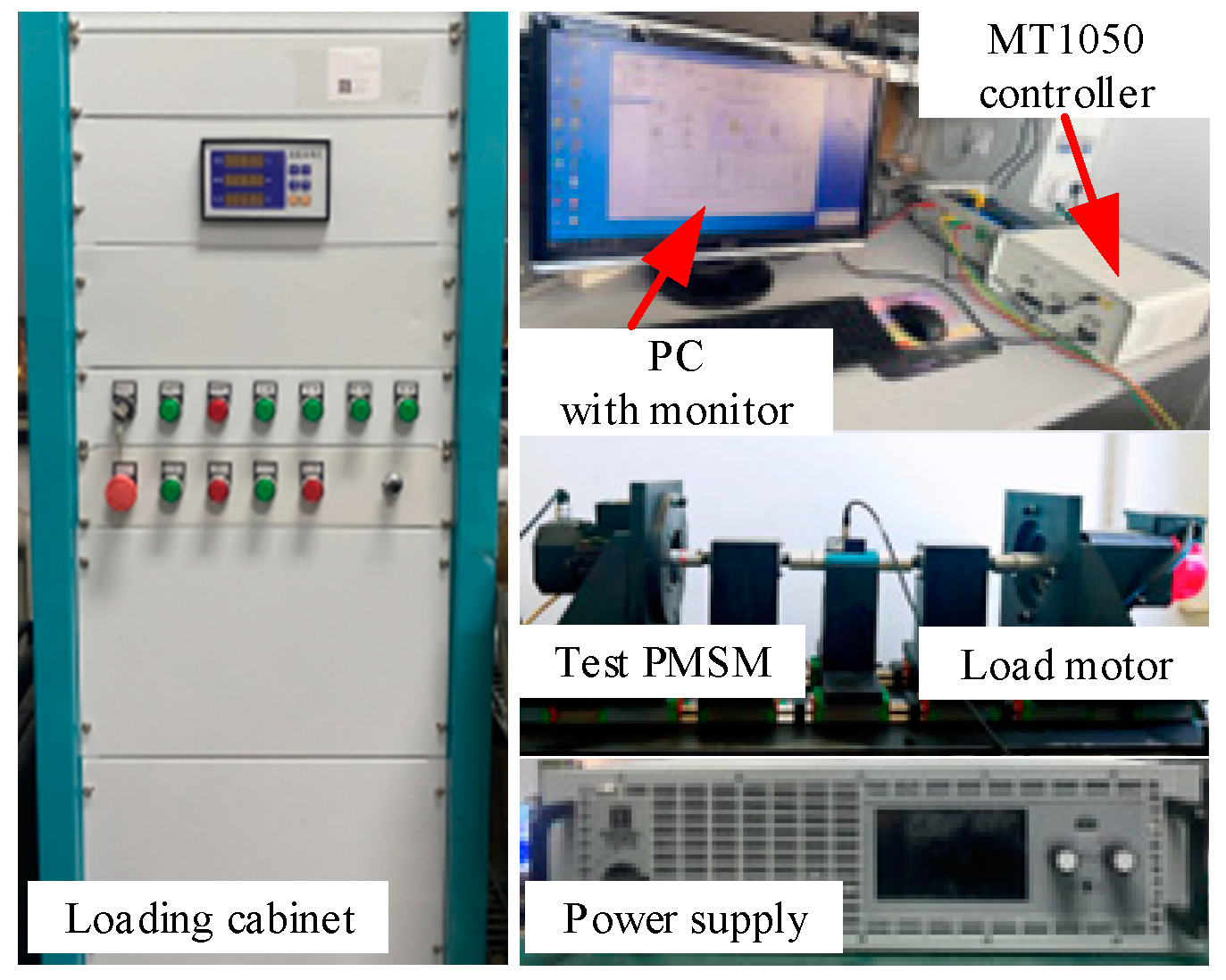
5. Experimental Research

To validate the effectiveness of the proposed method, an experimental platform was constructed, as shown in Figure 7. Experimental comparisons were conducted on the speed loops of PI, SMC, NSMC, and NSMC + SMTO, based on the MPCC current loop with a sliding mode disturbance observer. The control methods we studied were all validated on a PMSM test. The experimental system is primarily based on the MT1050 controller from Shanghai Yuan Kuan Energy Technology Co., Ltd., China, with its main control chip being TMS320F28335DSP from TI. The switching frequency of the driver during the experiment was 10 kHz, with a DC bus voltage of 310 V. Table 1 presents the parameters of the PMSM drive system.

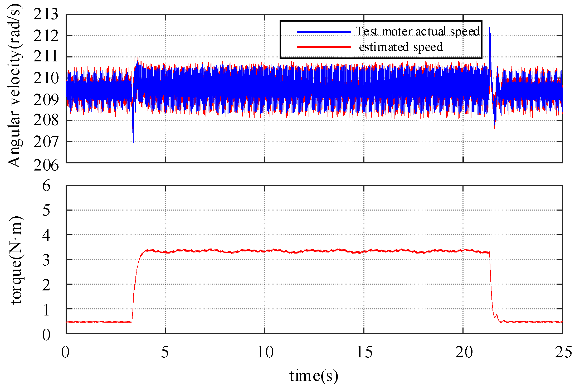
5.1. The Performance of the SMTO

Figure 8 shows the observation results of the SMTO for speed and load. The motor’s specified speed is 1000 rpm, equivalent to an electrical angular velocity of 209.44 rad/s. Due to mechanical installation errors, the experimentally inherent friction and damping of the system are 0.5 Nm, with an additional 3 Nm load torque applied during the experiment. As evident from Figure 8, the designed SMTO observer accurately observes the motor speed and load torque, with an observation time (the time required for the output signal to reach a stable value from when changes are made to the input signal in the control system) for load torque of 644 ms and an error (the ratio of the difference between the observer’s output and the actual value to the actual value) of 4.29%. The designed load torque observer can provide disturbance compensation for speed control.

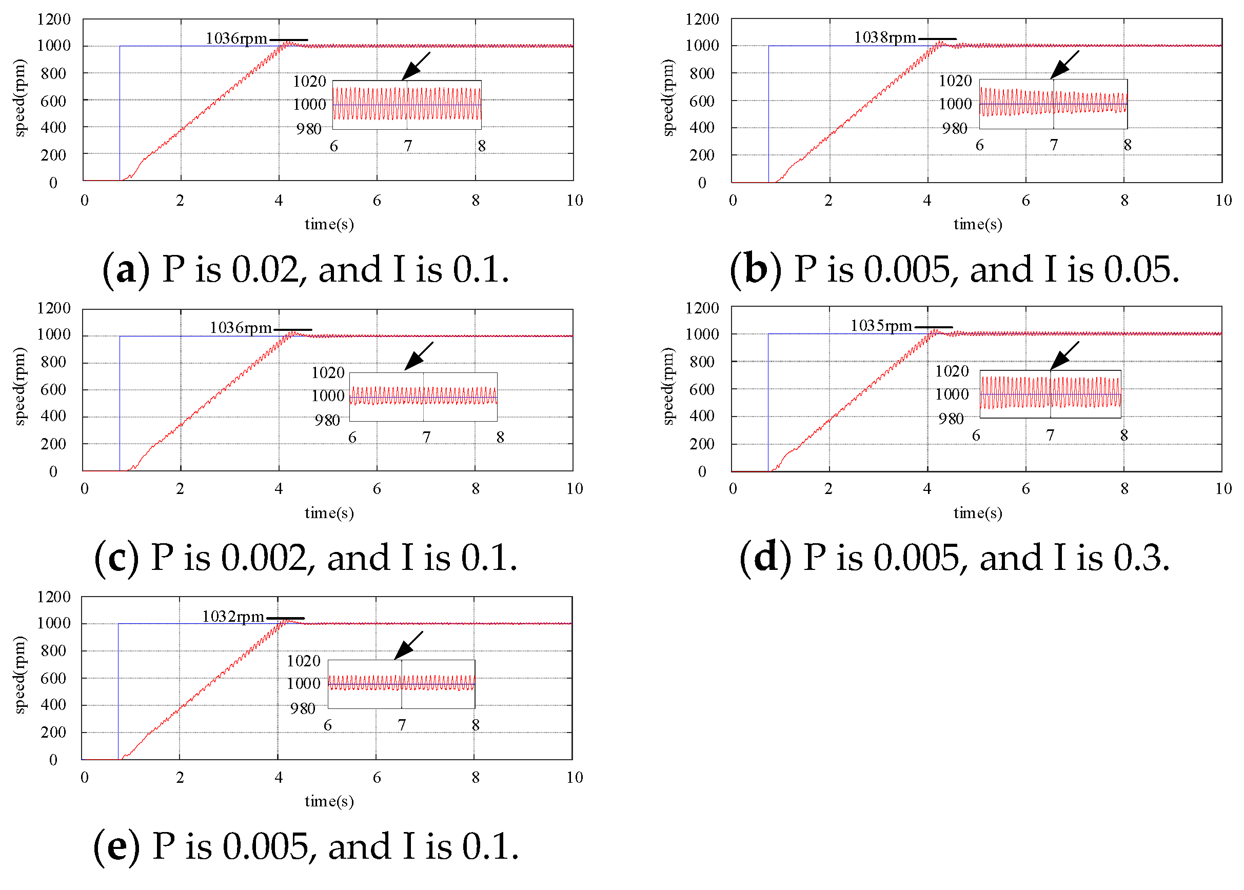
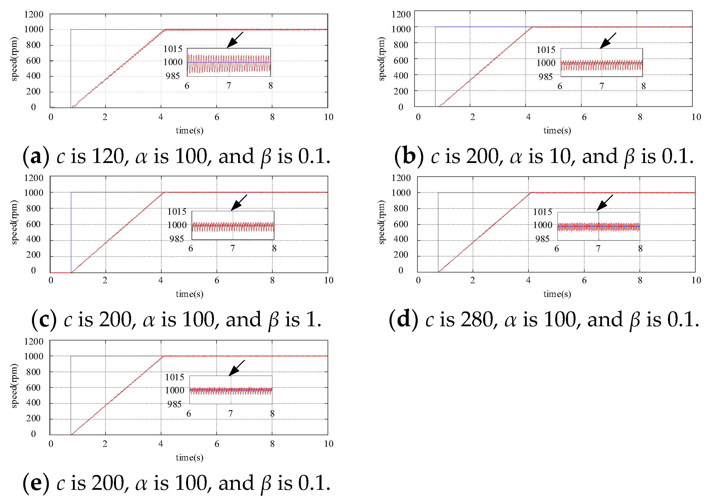
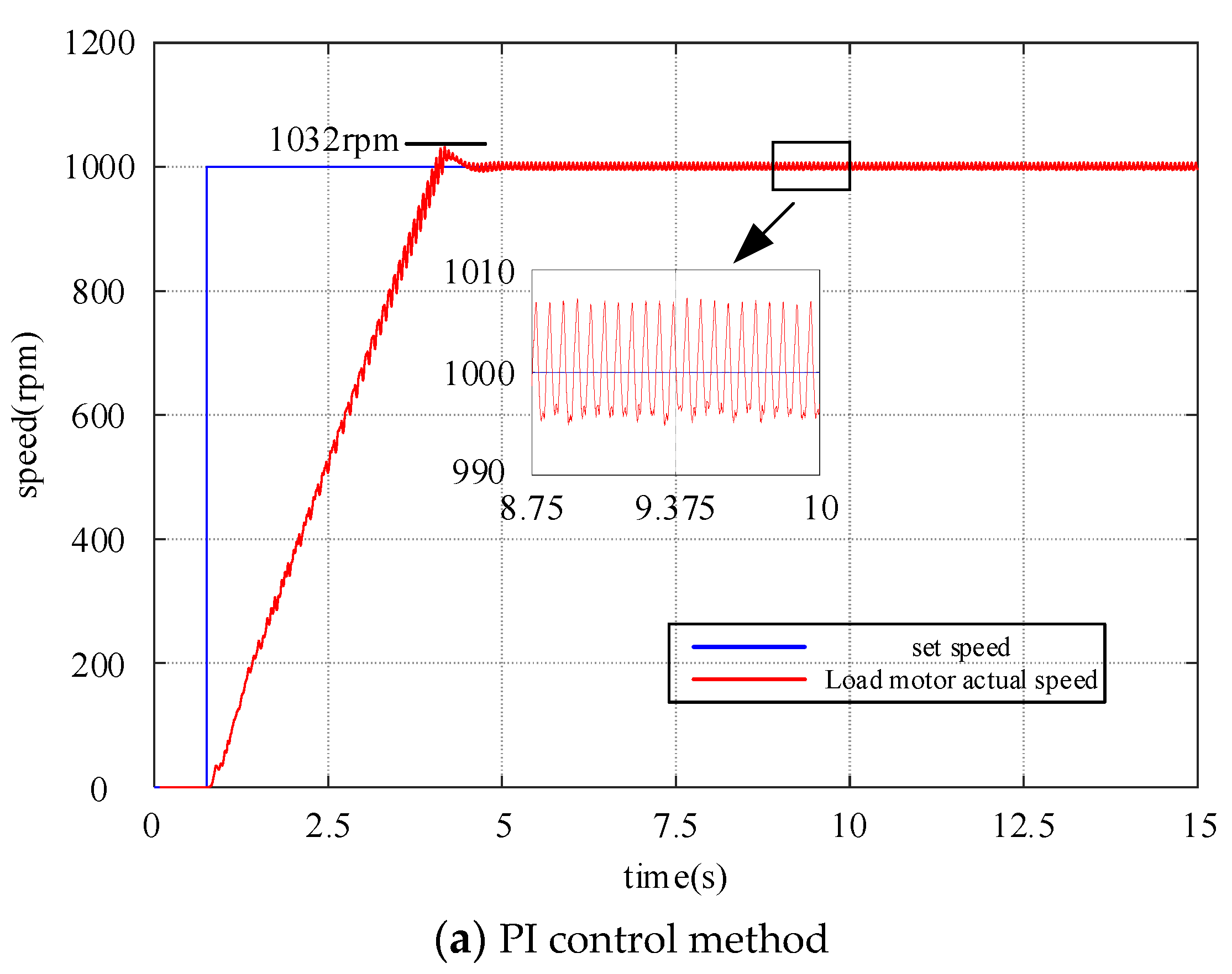
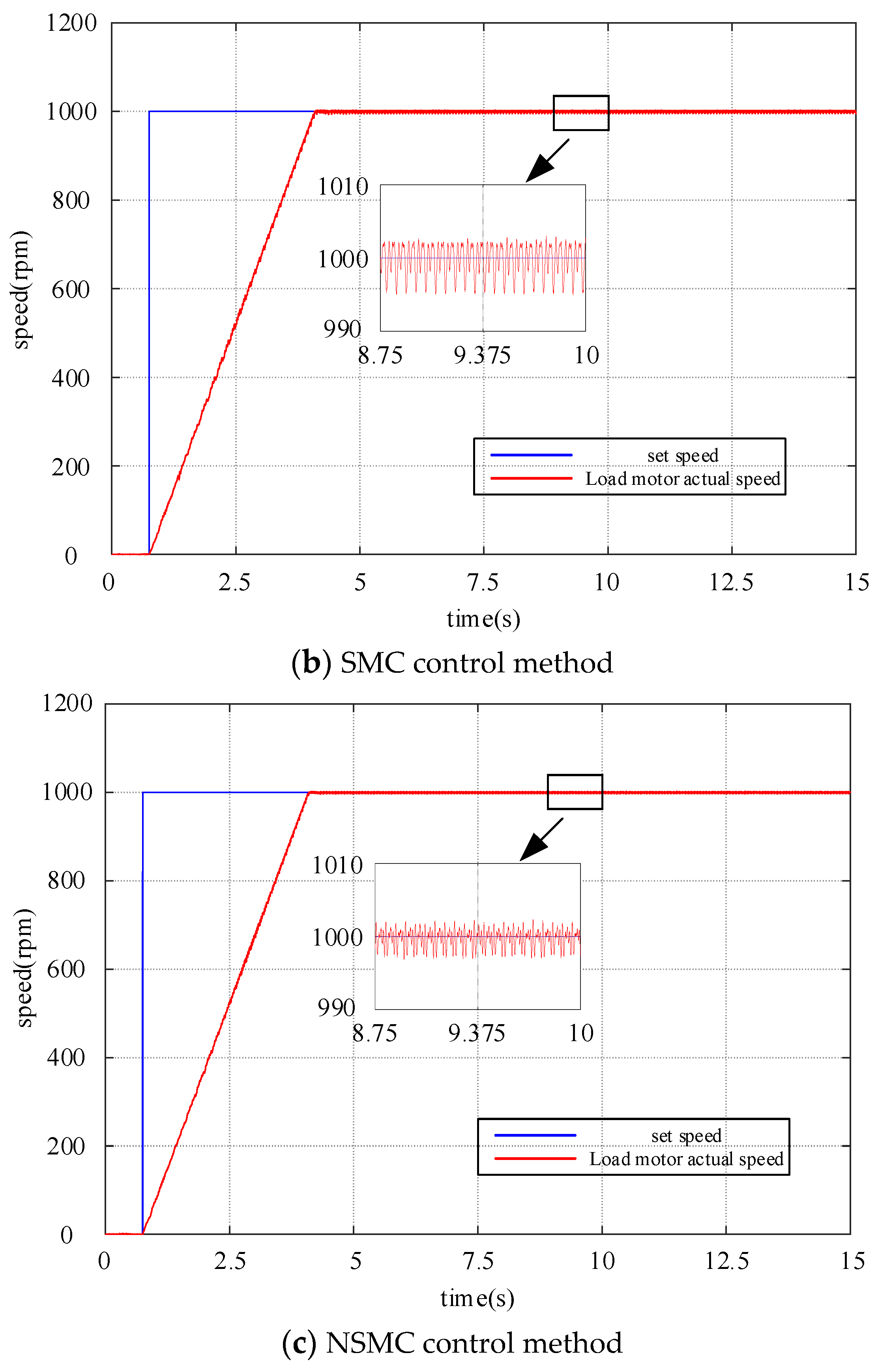
5.2. The Startup Performance of PMSM

This paper extensively compares the startup transient and steady-state speed performance of PMSM drive systems under PI, SMC, and NSMC control through experiments. Among these, the PI and SMC control methods are compared by selecting the optimal set of parameters through multiple experiments. Figure 9 and Figure 10 show the speed response waveforms of the PI control method and the SMC control method under different parameters, respectively. All controller parameters in the experiment are shown in Table 2. The SMC method is described in the preceding formula (19), and the NSMC method is described in the preceding formula (24). Two parameter speed values of 1000 rpm and 1500 rpm are set, respectively. Figure 11 illustrates the startup transient and steady-state speed performance under PI, SMC, and NSMC when the reference speed is set to 1000 rpm. PI exhibits an overshoot of 32 rpm, while SMC and NSMC show almost no overshoot. The response times of PI, SMC, and NSMC are 3.748 s, 3.373 s, and 3.369 s, respectively, with NSMC demonstrating the fastest response speed. In the steady state, the steady-state errors of PI, SMC, and NSMC are 6.5 rpm, 4 rpm, and 2.9 rpm, respectively, with NSMC exhibiting the least system oscillation.
Figure 12 illustrates the startup transient and steady-state speed performance under PI, SMC, and NSMC when the reference speed is set to 1500 rpm. PI exhibits an overshoot of 26 rpm, while SMC and NSMC show almost no overshoot. The response times of PI, SMC, and NSMC are 5.362 s, 5.029 s, and 5.012 s, respectively, with NSMC also demonstrating the fastest response speed. In the steady state, the steady-state errors of PI, SMC, and NSMC are 7.7 rpm, 5.9 rpm, and 4.5 rpm, respectively, with NSMC exhibiting the least system oscillation. From Figure 11 and Figure 12, it is evident that the startup and steady-state performance of NSMC are superior to PI and SMC, validating the correctness of the proposed NSMC method, which reduces both speed response time and system oscillation.
Furthermore, the startup and steady-state performance metrics of PI, SMC, and NSMC at speeds of 1000 rpm and 1500 rpm are listed separately, as shown in Table 3. The recovery time is the time required for the system to return to the set speed after a load disturbance, and the steady-state error is the maximum deviation between the actual speed and the set speed.

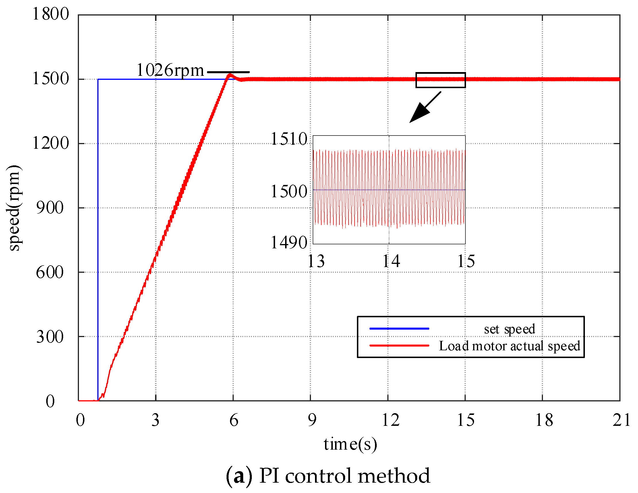
5.3. The Tracking Performance of PMSM

Through a series of experiments comparing the tracking performance of PI, SMC, and NSMC with the speed reference set as a sinusoidal wave varying between 800 and 1200 rpm. As shown in Figure 13, it is evident that NSMC’s tracking performance is significantly superior to that of PI and SMC. From the graph, it can be observed that the tracking errors of PI, SMC, and NSMC are 12.5 rpm, 10 rpm, and 5.5 rpm, respectively. The NSMC proposed in this paper exhibits better dynamic response characteristics compared to PI and SMC.

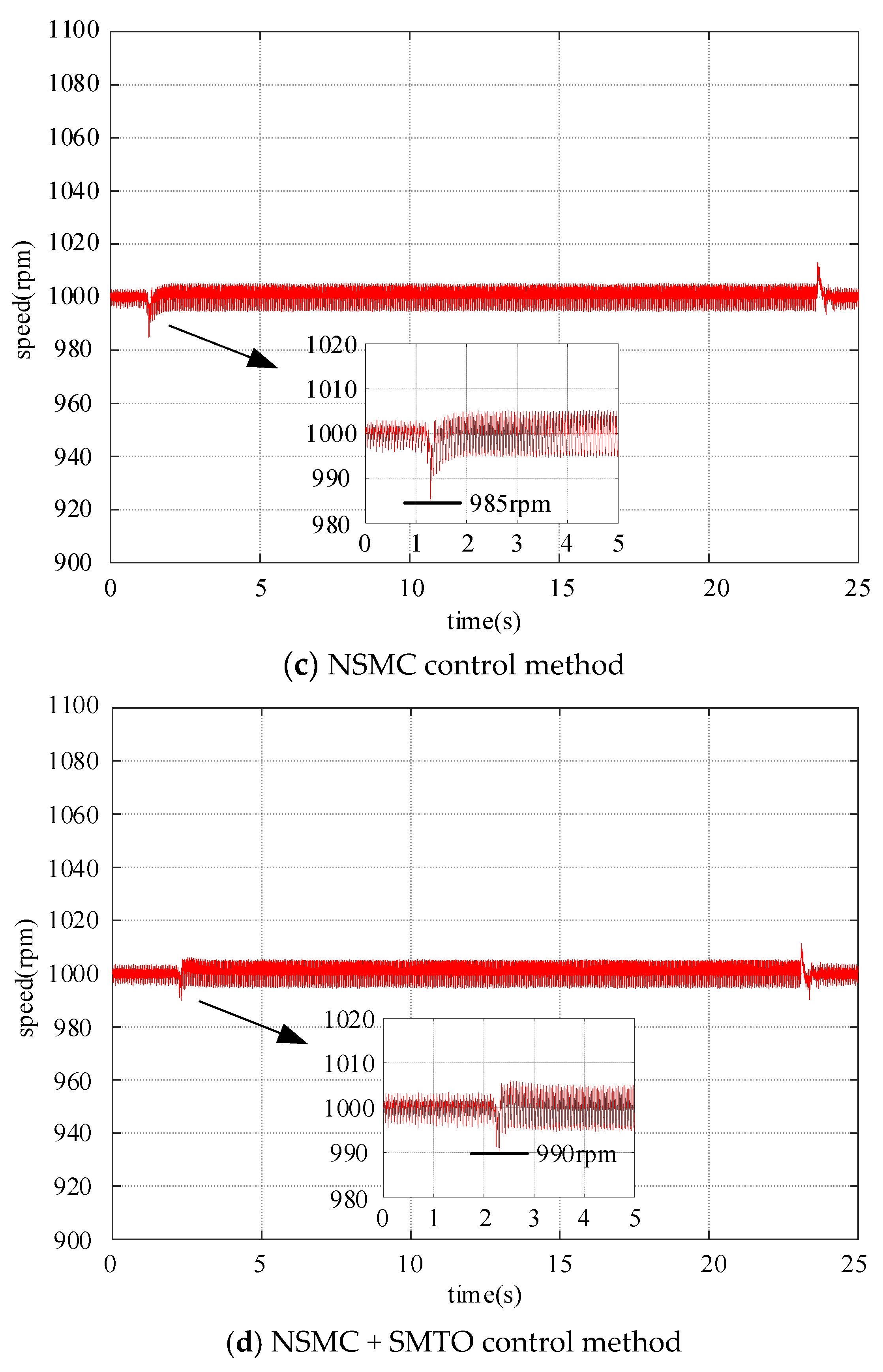
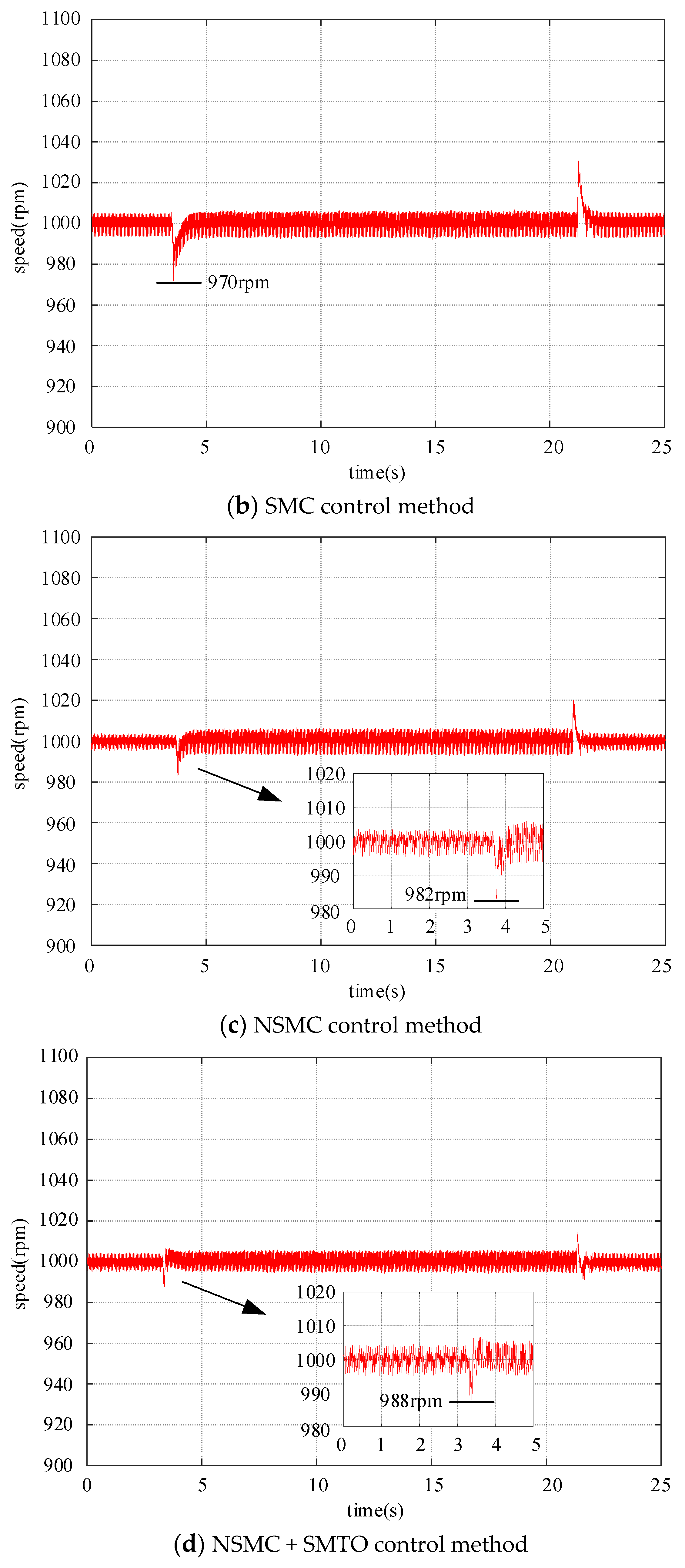
5.4. PMSM Load Disturbance Rejection Performance

At a speed of 1000 rpm, load disturbances of 2 Nm and 3 Nm were applied, and the robustness analysis of the PI, SMC, NSMC, and NSMC + SMTO methods to load disturbances was compared. Figure 14 and Figure 15 illustrate the speed performance of PI, SMC, NSMC, and NSMC + SMTO under load torques of 2 Nm and 3 Nm, respectively. From Figure 14, it can be seen that when the load is 2 Nm, the speed decrease and recovery times for PI, SMC, NSMC, and NSMC + SMTO are (50 rpm, 0.797 s), (24 rpm, 0.31 s), (15 rpm, 0.205 s), and (10 rpm, 0.115 s), respectively. Furthermore, through comparison, it can be noted that NSMC + SMTO exhibits the strongest robustness against external loads, with the shortest speed recovery time and an effectively reduced speed decrease.
To further demonstrate the effectiveness of the proposed method, Figure 15 illustrates the speed performance of PI, SMC, NSMC, and NSMC + SMTO under a load of 3 Nm. From Figure 15, it can be observed that the speed decrease and recovery times for PI, SMC, NSMC, and NSMC + SMTO are (60 rpm, 1.093 s), (30 rpm, 0.487 s), (18 rpm, 0.223 s), and (12 rpm, 0.122 s), respectively. Through comparison, it can be inferred that NSMC + SMTO exhibits the strongest robustness against external loads, with the shortest speed recovery time and an effectively reduced speed decrease.
Therefore, Table 4 lists the speed decrease and recovery times of PI, SMC, NSMC, and NSMC + SMTO under load torques of 2 Nm and 3 Nm, respectively. From the table, it is clearer that NSMC + SMTO exhibits better resistance to load disturbances and dynamic performance compared to PI, SMC, and NSMC.

6. Conclusions

To improve the response speed of the speed controller, reduce vibration, and enhance its resistance to load disturbances, this paper proposes a novel sliding mode velocity controller based on MPCC with a disturbance observer. The following conclusions are drawn from the theoretical analysis and experimental studies:
(1)
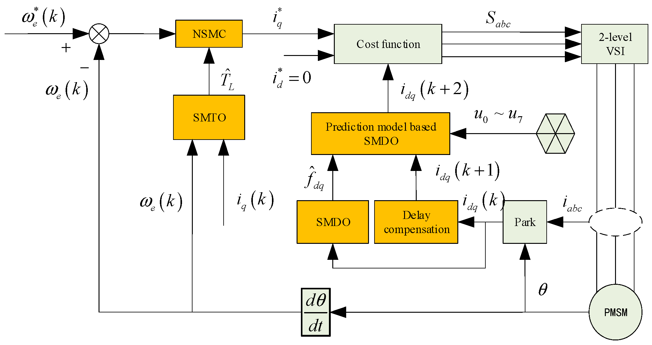
Firstly, to enhance the parameter robustness of MPCC, a disturbance observer-based MPCC is designed. Subsequently, a NSMC is proposed in the velocity loop, effectively suppressing vibration phenomena and ensuring fast convergence and steady-state characteristics.
(2)
The NSMC controller exhibits superior tracking performance. Experimental results show that, compared to PI and SMC, the NSMC controller achieves the smallest tracking error, effectively enhancing the control performance of the system.
(3)
Designing a sliding mode load torque observer to provide real-time feedback on the load torque value to the control system enables speed compensation control, thereby enhancing the system’s disturbance rejection capability.
The NSMC + SMTO algorithm proposed in this paper is extensively compared with the PI and SMC methods under loaded and unloaded conditions, validating the dynamic characteristics and disturbance rejection capabilities of the proposed approach. The stability of this algorithm is verified through Lyapunov theory, and the experimental results confirm its correctness.

Author Contributions

Conceptualization, W.Z. and Z.S.; methodology, W.Z.; software, W.Z.; validation, W.Z., X.X. and Y.G.; formal analysis, Z.S.; investigation, Y.M.; resources, Z.S.; data curation, Z.S.; writing—original draft preparation, W.Z.; writing—review and editing, W.Z.; visualization, X.X.; supervision, X.X.; project administration, Y.G.; funding acquisition, X.X. All authors have read and agreed to the published version of the manuscript.

Funding

This research was funded in part by the National Key Research and Development Project of China under grant number 2020YFE0205400, and in part by the National Natural Science Foundation of China under grant number 52337002 and grant number 52305541.

Data Availability Statement

The data presented in this study are available on request from the corresponding authors.

Acknowledgments

Thanks to all the Project team members.

Conflicts of Interest

The authors declare no conflict of interest.

References

  1. Xu, J.; Guo, S.; Guo, H.; Tian, X. Fault-Tolerant Current Control of Six-Phase Permanent Magnet Motor With Multifrequency Quasi-Proportional-Resonant Control and Feedforward Compensation for Aerospace Drives. IEEE Trans. Power Electron. 2023, 38, 283–293. [Google Scholar] [CrossRef]
  2. Zhang, W.; Zhang, Z.; Wen, L.; Jiang, W.; Gu, X.; Li, Y. Multigain Online Autotuning Technique-Based Discrete-Time Current Regulator for Permanent Magnet Synchronous Motors. IEEE Trans. Power Electron. 2024, 39, 260–269. [Google Scholar] [CrossRef]
  3. Jing, H.; Chen, Z.; Wang, X.; Wang, X.; Ge, L.; Fang, G.; Xiao, D. Gradient Boosting Decision Tree for Rotor Temperature Estimation in Permanent Magnet Synchronous Motors. IEEE Trans. Power Electron. 2023, 38, 10617–10622. [Google Scholar] [CrossRef]
  4. Brosch, A.; Tinazzi, F.; Wallscheid, O.; Zigliotto, M.; Böcker, J. Finite Set Sensorless Control With Minimum a Priori Knowledge and Tuning Effort for Interior Permanent-Magnet Synchronous Motors. IEEE Trans. Power Electron. 2023, 38, 12508–12519. [Google Scholar] [CrossRef]
  5. Schenke, M.; Haucke-Korber, B.; Wallscheid, O. Finite-Set Direct Torque Control via Edge-Computing-Assisted Safe Reinforcement Learning for a Permanent-Magnet Synchronous Motor. IEEE Trans. Power Electron. 2023, 38, 13741–13756. [Google Scholar] [CrossRef]
  6. Gao, J.; Gong, C.; Li, W.; Liu, J. Novel Compensation Strategy for Calculation Delay of Finite Control Set Model Predictive Current Control in PMSM. IEEE Trans. Ind Electron. 2020, 67, 5816–5819. [Google Scholar] [CrossRef]
  7. Zhang, X.; Zhang, L.; Zhang, Y. Model Predictive Current Control for PMSM Drives With Parameter Robustness Improvement. IEEE Trans. Power Electron. 2019, 34, 1645–1657. [Google Scholar] [CrossRef]
  8. Sun, Z.; Deng, Y.; Wang, J.; Yang, T.; Wei, Z.; Cao, H. Finite Control Set Model-Free Predictive Current Control of PMSM With Two Voltage Vectors Based on Ultralocal Model. IEEE Trans. Power Electron. 2023, 38, 776–788. [Google Scholar] [CrossRef]
  9. Wei, Y.; Young, H.; Ke, D.; Huang, D.; Wang, F.; Rodríguez, J. Adaptive Ultralocalized Time-Series for Improved Model-Free Predictive Current Control on PMSM Drives. IEEE Trans. Power Electron. 2024, 39, 5155–5165. [Google Scholar] [CrossRef]
  10. Liu, X.; Yang, H.; Lin, H.; Yu, F.; Yang, Y. A Novel Finite-Set Sliding-Mode Model-Free Predictive Current Control for PMSM Drives Without DC-Link Voltage Sensor. IEEE Trans. Power Electron. 2024, 39, 320–331. [Google Scholar] [CrossRef]
  11. Liu, H.; Lin, W.; Liu, Z.; Buccella, C.; Cecati, C. Model Predictive Current Control With Model-Aid Extended State Observer Compensation for PMSM Drive. IEEE Trans. Power Electron. 2023, 38, 3152–3162. [Google Scholar] [CrossRef]
  12. Li, X.; Tian, W.; Gao, X.; Yang, Q.; Kennel, R. A Generalized Observer-Based Robust Predictive Current Control Strategy for PMSM Drive System. IEEE Trans. Ind. Electron. 2020, 69, 1322–1332. [Google Scholar] [CrossRef]
  13. Yin, Z.; Han, X.; Du, C.; Liu, J.; Zhong, Y. Research on Model Predictive Current Control for Induction Machine Based on Immune-Optimized Disturbance Observer. IEEE J. Emerg. Sel. Top. Power Electron. 2018, 6, 1699–1710. [Google Scholar] [CrossRef]
  14. Tao, T.; Zhao, W.; Du, Y.; Cheng, Y.; Zhu, J. Simplified Fault-Tolerant Model Predictive Control for a Five-Phase Permanent-Magnet Motor With Reduced Computation Burden. IEEE Trans. Power Electron. 2020, 35, 3850–3858. [Google Scholar] [CrossRef]
  15. Sun, X.; Tang, Y.; Xiao, X.; Xie, Y. Predictive Trajectory Control Strategy for Permanent Magnet Synchronous Motor Drives Based on Deadbeat Predictive Flux Linkage Control Method. IEEE Trans. Power Electron. 2023, 38, 2327–2338. [Google Scholar] [CrossRef]
  16. Ismail, M.M.; Xu, W.; Ge, J.; Tang, Y.; Junejo, A.K.; Hussien, M.G. Adaptive Linear Predictive Model of an Improved Predictive Control of Permanent Magnet Synchronous Motor Over Different Speed Regions. IEEE Trans. Power Electron. 2022, 37, 15338–15355. [Google Scholar] [CrossRef]
  17. Brosch, A.; Wallscheid, O.; Böcker, J. Time-Optimal Model Predictive Control of Permanent Magnet Synchronous Motors Considering Current and Torque Constraints. IEEE Trans. Power Electron. 2023, 38, 7945–7957. [Google Scholar] [CrossRef]
  18. Chaoui, H.; Khayamy, M.; Okoye, O.; Gualous, H. Simplified Speed Control of Permanent Magnet Synchronous Motors Using Genetic Algorithms. IEEE Trans. Power Electron. 2019, 34, 3563–3574. [Google Scholar] [CrossRef]
  19. Huang, K.; Peng, W.; Lai, C.; Feng, G. Efficient Maximum Torque Per Ampere (MTPA) Control of Interior PMSM Using Sparse Bayesian Based Offline Data-Driven Model With Online Magnet Temperature Compensation. IEEE Trans. Power Electron. 2023, 38, 5192–5203. [Google Scholar] [CrossRef]
  20. Lin, F.J.; Wang, P.L.; Hsu, I.M. Intelligent Nonsingular Terminal Sliding Mode Controlled Nonlinear Time-Varying System Using RPPFNN-AMF. IEEE Trans. Fuzzy Syst. 2024, 32, 1036–1049. [Google Scholar] [CrossRef]
  21. Wu, T.; Feng, Z.; Wu, C.; Lei, G.; Guo, Y.; Zhu, J.; Wang, X. Multiobjective Optimization of a Tubular Coreless LPMSM Based on Adaptive Multiobjective Black Hole Algorithm. IEEE Trans. Ind Electron. 2020, 67, 3901–3910. [Google Scholar] [CrossRef]
  22. Zhao, J.; Yang, C.; Gao, W.; Zhou, L. Reinforcement Learning and Optimal Control of PMSM Speed Servo System. IEEE Trans. Ind. Electron. 2023, 70, 8305–8313. [Google Scholar] [CrossRef]
  23. Zheng, B.; Zou, J.; Li, B.; Tang, M.; Xu, Y.; Zanchetta, P. Analysis and Fault-Tolerant Control for Dual-Three-Phase PMSM Based on Virtual Healthy Model. IEEE Trans. Power Electron. 2022, 37, 15411–15424. [Google Scholar] [CrossRef]
  24. Fu, D.; Zhao, X.; Zhu, J. A Novel Robust Super-Twisting Nonsingular Terminal Sliding Mode Controller for Permanent Magnet Linear Synchronous Motors. IEEE Trans. Power Electron. 2022, 37, 2936–2945. [Google Scholar] [CrossRef]
  25. Wu, G.; Huang, S.; Wu, Q.; Rong, F.; Zhang, C.; Liao, W. Robust Predictive Torque Control of N*3-Phase PMSM for High-Power Traction Application. IEEE Trans. Power Electron. 2020, 35, 10799–10809. [Google Scholar] [CrossRef]
  26. Li, Z.; Wang, F.; Ke, D.; Li, J.; Zhang, W. Robust Continuous Model Predictive Speed and Current Control for PMSM With Adaptive Integral Sliding-Mode Approach. IEEE Trans. Power Electron. 2021, 36, 14398–14408. [Google Scholar] [CrossRef]
  27. Song, X.; Wang, H.; Ma, X.; Yuan, X.; Wu, X. Robust Model Predictive Current Control for a Nine-Phase Open-End Winding PMSM With High Computational Efficiency. IEEE Trans. Power Electron. 2023, 38, 13933–13943. [Google Scholar] [CrossRef]
  28. Li, H.; Wang, S.; Xie, Y.; Zheng, S.; Shi, P. Virtual Reference-Based Fuzzy Noncascade Speed Control for PMSM Systems With Unmatched Disturbances and Current Constraints. IEEE Trans. Fuzzy Syst. 2023, 31, 4249–4261. [Google Scholar] [CrossRef]
  29. Zhao, K.; Chen, X.; Liu, J.; Yu, J. Discrete-Time Adaptive Fuzzy Event-Triggered Control for PMSMs With Voltage Faults via Command Filter Approximator. IEEE Trans. Power Electron. 2024, 39, 7343–7350. [Google Scholar] [CrossRef]
  30. Yeam, T.I.; Lee, D.C. Design of Sliding-Mode Speed Controller With Active Damping Control for Single-Inverter Dual-PMSM Drive Systems. IEEE Trans. Power Electron. 2021, 36, 5794–5801. [Google Scholar] [CrossRef]
  31. Xu, W.; Junejo, A.K.; Liu, Y.; Hussien, M.G.; Zhu, J. An Efficient Antidisturbance Sliding-Mode Speed Control Method for PMSM Drive Systems. IEEE Trans. Power Electron. 2021, 36, 6879–6891. [Google Scholar] [CrossRef]
  32. Wang, Y.; Feng, Y.; Zhang, X.; Liang, J. A New Reaching Law for Antidisturbance Sliding-Mode Control of PMSM Speed Regulation System. IEEE Trans. Power Electron. 2020, 35, 4117–4126. [Google Scholar] [CrossRef]
  33. Lian, C.; Xiao, F.; Gao, S.; Liu, J. Load Torque and Moment of Inertia Identification for Permanent Magnet Synchronous Motor Drives Based on Sliding Mode Observer. IEEE Trans. Power Electron. 2019, 34, 5675–5683. [Google Scholar] [CrossRef]
  34. Tang, S.; Shi, T.; Cao, Y.; Lin, Z.; Wang, Z.; Yan, Y. Simultaneous Identification of Load Torque and Moment of Inertia of PMSM Based on Variable Structure Extended Sliding Mode Observer. IEEE Trans. Power Electron. 2024, 39, 8585–8596. [Google Scholar] [CrossRef]
  35. Gu, M.; Wang, Z.; Wang, B. Optimization of Torque Ripple for Low-Carrier-Ratio Dual Three-Phase PMSM With Pulse Pattern Control. IEEE Trans. Power Electron. 2023, 38, 15091–15096. [Google Scholar] [CrossRef]
  36. Yu, K.; Wang, Z. An Online Compensation Method of VSI Nonlinearity for Dual Three-Phase PMSM Drives Using Current Injection. IEEE Trans. Power Electron. 2022, 37, 3769–3774. [Google Scholar] [CrossRef]
  37. Ge, Y.; Song, W.; Yang, Y.; Wheeler, P. A Polar-Coordinate-Multisignal-Flux-Observer-Based PMSM Non-PLL Sensorless Control. IEEE Trans. Power Electron. 2023, 38, 10579–10583. [Google Scholar] [CrossRef]
  38. Zhang, X.; He, Y. Direct Voltage-Selection Based Model Predictive Direct Speed Control for PMSM Drives Without Weighting Factor. IEEE Trans. Power Electron. 2019, 34, 7838–7851. [Google Scholar] [CrossRef]
  39. Zhang, C.; Wu, G.; Rong, F.; Feng, J.; Jia, L.; He, J.; Huang, S. Robust Fault-Tolerant Predictive Current Control for Permanent Magnet Synchronous Motors Considering Demagnetization Fault. IEEE Trans. Ind. Electron. 2018, 65, 5324–5334. [Google Scholar] [CrossRef]
  40. Zhang, X.; Cheng, Y.; Zhao, Z.; He, Y. Robust Model Predictive Direct Speed Control for SPMSM Drives Based on Full Parameter Disturbances and Load Observer. IEEE Trans. Power Electron. 2020, 35, 8361–8373. [Google Scholar] [CrossRef]
Figure 1. The principle diagram of MPCC.
Electronics 13 02561 g001
Figure 2. The influence of different parameter errors on the predicted d-axis current at a speed of 1000 r/min.
Electronics 13 02561 g002
Figure 3. The influence of different parameter errors on the predicted q-axis current at a speed of 1000 r/min.
Electronics 13 02561 g003
Figure 4. Piecewise square-root switching function.
Electronics 13 02561 g004
Figure 5. Schematic diagram of the SMTO.
Electronics 13 02561 g005
Figure 6. Schematic diagram of sliding mode speed control based on model predictive current control for permanent magnet synchronous motors.
Electronics 13 02561 g006
Figure 7. Experimental platform.
Electronics 13 02561 g007
Figure 8. Torque observer observation waveform.
Electronics 13 02561 g008
Figure 9. Speed response under different parameters in the PI control method.
Electronics 13 02561 g009
Figure 10. Speed response under different parameters in the SMC control method.
Electronics 13 02561 g010
Figure 11. Speed response under no-load conditions at 1000 rpm.
Electronics 13 02561 g011aElectronics 13 02561 g011b
Figure 12. Speed response under no-load conditions at 1500 rpm.
Electronics 13 02561 g012aElectronics 13 02561 g012b
Figure 13. Speed tracking performance.
Electronics 13 02561 g013
Figure 14. Speed response under 1000 rpm and 2 Nm load step change.
Electronics 13 02561 g014aElectronics 13 02561 g014b
Figure 15. Speed response under 1000 rpm and 3 Nm load step change.
Electronics 13 02561 g015aElectronics 13 02561 g015b
Table 1. PMSM Parameters.
ParameterValueParameterValue
Rated power3.0 kWParameters magnet flus linkage ψf0.2811 Wb
Rated speed3000 rpmStator inductance Ld6.3 mH
Rated current5.0 AStator inductance Lq16 mH
Number of pole-pairs2Stator resistance R1.386 Ω
Table 2. The parameters of each controller in the experiment.
PISMCNSMCSMTO
P0.005c200c200k−20,000
a100a100
I0.1β0.1β0.1g−0.01
γ0.5
Table 3. Performance metrics of speed response for PI, SMC, and NSMC.
Control MethodRecovery Time (s) at Speeds of 1000 r/min and 1500 r/minSteady-State Error (±rpm) at Speeds of 1000 r/min and 1500 r/min
PI3.7485.3626.57.7
SMC3.3735.02945.9
NSMC3.3695.0122.94.5
Table 4. Performance indicators of load disturbance rejection for PI, SMC, NSMC, and NSMC + SMTO.
Control TechniqueSpeed Decrease (rpm) and Recovery Time (s) with 2 Nm LoadSpeed Decrease (rpm) and Recovery Time (s) with 3 Nm Load
PI500.797601.093
SMC240.31300.487
NSMC150.205180.223
NSMC + SMTO100.115120.122
Disclaimer/Publisher’s Note: The statements, opinions and data contained in all publications are solely those of the individual author(s) and contributor(s) and not of MDPI and/or the editor(s). MDPI and/or the editor(s) disclaim responsibility for any injury to people or property resulting from any ideas, methods, instructions or products referred to in the content.

