Article

Self-Powered System Development with Organic Photovoltaic (OPV) for Energy Harvesting from Indoor Lighting

by
Eder Andrade da Silva
1,2,
Werner Moreira Chaves Filho
2,
Marco Roberto Cavallari
2,3 and
Oswaldo Hideo Ando Junior
1,2,4,*
1
Interdisciplinary Postgraduate Program in Energy & Sustainability (PPGIES), Federal University of Latin American Integration—UNILA, Foz do Iguaçu 85867-000, PR, Brazil
2
Research Group on Energy & Energy Sustainability (GPEnSE), Academic Unit of Cabo de Santo Agostinho (UACSA), Federal Rural University of Pernambuco (UFRPE), Cabo de Santo Agostinho 54518-430, PE, Brazil
3
Faculdade de Engenharia Elétrica e de Computação (FEEC), Universidade Estadual de Campinas (UNICAMP), Av. Albert Einstein 400, Campinas 13083-852, SP, Brazil
4
Program in Energy Systems Engineering (PPGESE) Academic Unit of Cabo de Santo Agostinho (UACSA), Federal Rural University of Pernambuco (UFRPE), Cabo de Santo Agostinho 54518-430, PE, Brazil
*
Author to whom correspondence should be addressed.
Electronics 2024, 13(13), 2518; https://doi.org/10.3390/electronics13132518
Submission received: 28 May 2024 / Revised: 21 June 2024 / Accepted: 23 June 2024 / Published: 27 June 2024

Abstract

:
The increase in demand for electricity due to industrial development and the growing use of electronic equipment has led to the need for new alternative energy sources, such as photovoltaic solar energy conversion. In this context, organic photovoltaic (OPV) stands out as an efficient way of generating energy indoors. An electrical power supply system (EPS) was developed to power a commercial electronic lock, using OPV as the energy source. The system was designed with a charging control to match the panel voltage to a supercapacitor charge accumulator and a boost converter. Tests on the bench and in a real scenario demonstrated the viability and effectiveness of the system, showing that it is capable of operating self-sufficiently with a minimum daily illuminance of 250 lux for 12 h. The results indicate that the system can be applied to various loads with low energy consumption, promoting energy efficiency in different contexts.

1. Introduction

The constant development of the world’s industrial sector, together with theincreased use of electronic equipment, has meant that the demand for electricity has increased exponentially in recent decades, causing bottlenecks in energy generation systems [1,2].
With the introduction of new alternative energy sources as a means of solving a growing energy demand and in order to reduce the use of traditional sources of energy generation that cause severe environmental impacts, the demand for the development of technologies that make it possible to accelerate this energy transition has been growing exponentially. Among the options available, photovoltaic solar energy conversion stands out as one of the most important forms of energy generation in the energy transition. In this context, new photovoltaic technologies have been introduced, such as organic photovoltaic (OPV), a light and semi-transparent organic photovoltaic film, which, due to its high efficiency in indoor micro-generation applications, has gained visibility in the market and created a growing demand for equipment that enables its application on a large scale [3,4].
Motivated by this scenario, a partner company requested the development of an electrical power supply system (EPS) that uses the OPV as a source of energy generation to power a commercial electronic lock. This request aligns with the growing interest in sustainable and renewable energy solutions, particularly in applications where traditional batteries can be impractical due to frequent replacement needs and environmental concerns. The OPV technology, with its high efficiency in converting indoor lighting to electrical energy, presents a promising alternative [3,4]. To address the specific energy requirements of the electronic lock, the EPS was designed to include a charging control mechanism that optimizes the voltage from the OPV panels, a supercapacitor for efficient energy storage, and a boost converter with extremely low standby power consumption. Comprehensive testing under various lighting conditions confirmed the system’s capability to maintain self-sufficient operation with a minimum daily illuminance of 250 lux for 12 h, thereby validating its practicality and effectiveness for real-world applications [4,5]. This development not only demonstrates the feasibility of using OPV for low power electronic devices but also highlights the potential for broader application in the pursuit of energy-efficient solutions.
Following the introduction and motivation for the project are the details of the methodological outline for the survey of the bibliographic portfolio, the analysis of the state of the art, the development and manufacture of the prototypes, the results and discussions on the prototype development process, and, finally, the conclusions of the development.

2. Energy Harvesting for Self-Powered Systems

The search, analysis, and selection of relevant scientific works, known as the bibliographic portfolio (BP), is a fundamental stage in any academic research or development. The BP is used to support the theoretical framework. In this work, the scientific literature review on the subject of Energy Harvesting for Self-Powered Systems (EHSPS) was carried out using the Proknow-C scientific and constructivist approach methodology [6,7].
The Proknow-C method consists of a sequence of procedures that systematize the survey of a bibliographic portfolio of works relevant to the research topic. To this end, Proknow-C includes the following stages [6]: (A) Selection of a portfolio of articles relevant to the research topic; (B) Bibliometric analysis of the portfolio; (C) Systemic analysis of the bibliographic portfolio; (D) Definition of the research question and objectives. For this work, in order to obtain a bibliographic portfolio on the subject, phases “A” and “C” were carried out, which correspond to the stages of surveying and defining the works present in the BP.

2.1. Selection of the Bibliographic Portfolio

As a first step in the method, keywords (PCs) and their combinations were identified to guide the search. The combinations are: (i) “Organic Photovoltaic” AND “Supercapacitor”; (ii) “Organic Photovoltaic” AND “buck-boost” and (iii) “Organic Photo-voltaic” AND “Self-powered”.
A search was then carried out using Publish or Perish® bibliographic reference search software (version: 8.8.4383) in three major academic article databases. These were: Google Scholar (GS), SCOPUS (SCP), and Web of Science (WoS). The results of the searches carried out are described in Table 1.
The search results were exported to the Excel® spreadsheet tool and submitted to a Python script to filter out the articles with the most relevant titles for the development of this project. The result was a database of 101 articles with compatible titles, which were selected to make up the “K” and “P” repositories.
The “K” repository is made up of 13 articles, which accumulate 80% of the total citations in the filtered portfolio, with a cut-off score of 50 citations. The remaining articles were analyzed in relation to their titles and were included in the “P” repository, made up of 28 publications, which, according to [6], form repository “C,” listed in Table 2.
Of the 28 articles in the PB, 13 are reviews on the subject, making up 46.42% of the articles in the PB. The remainder revolved around the development of projects, proposing new self-powered integration methods.
In order to compose the state of the art and contribute to the development of this work, we propose an analysis of the remaining 15 articles (53.58%), which provide an exploratory and experimental approach to EHSPS projects.
Thus, of the articles in the PB of this experimental nature, after reading them in full, the articles mentioned in the next section were selected to make up the state of the art in EHSPS, taking into account their contribution to the topic and to this project.

2.2. Systemic Analysis Bibliographic Portfolio

After selecting the articles, it is essential to carry out a systemic analysis of the bibliographic portfolio. At this stage, the content of each paper is assessed in terms of its contribution to the state of the art. The techniques and materials used, the difficulties encountered, and the positive and negative points of each work are analyzed, as well as the similarities between the articles in the BP. This analysis makes it possible to obtain information that helps to synthesize and interpret the results, as well as directing future work.
Among the articles selected from repository C, there is a focus on the development of self-powered systems with flexible supercapacitors as a means of energy storage, and the development of DC–DC converters. A secondary theme is a description of the use and implementation of Maximum Power Point Tracking (MPPT) techniques.
Self-powered systems are applications of the energy harvesting concept in systems where there is a partial or complete supply from the system itself. There is the following cycle: the energy available in the environment is captured, conditioned, stored, and used to power the load. Micro-generators (energy harvesting) act to capture the energy present in the environment, which is commonly indoor in this type of arrangement. The energy harvested is controlled and conditioned by the system’s EPS equipment, which converts, manages, and stores the energy to be consumed by the load present in the system. A simplified diagram of this type of system is shown in Figure 1.
In [17], a self-powered system utilizing organic photovoltaic (OPV) technology is developed to power an SL900A-TAG RFID tag sensor. Initially, the OPV module’s characteristics, including I-V and power-versus-voltage (P-V) curves, are evaluated. The system’s performance is subsequently compared with that of a 0.5 W Si-PV silicon solar panel and a 3.3 V coin-shaped lithium battery when connected to the sensor. A test bench is utilized to gather input and output data for comprehensive analysis and comparison.
Additionally, ref. [17] details the fabrication process of printing a flexible supercapacitor directly onto an OPV to form a monolithically integrated energy module. This integrated system’s performance was assessed over a period of 90 h, demonstrating a capacitor voltage measurement of 1000 mV. Additionally, the development includes integrating printed supercapacitors with OPV cells to power a flexible temperature recorder. This recorder incorporates an integrated circuit (IC), a coil antenna, and an energy source. While the IC enables on-demand temperature measurements and autonomous data logging, it requires an additional 3 V lithium battery for operation.
In [3], the application of flexible supercapacitors (SCs) combined with organic photovoltaic (OPV) cells in self-sufficient systems is highlighted. These systems leverage the flexibility of OPV cells and SCs to provide energy to devices or sensors, particularly emphasizing applications in wearable technology due to their adaptability. As detailed in [3], a self-powered system has been developed integrating a 3 µm thick OPV with a 40 µm flexible capacitor, achieving an impressive energy conversion efficiency of 96%.
In applications that use energy from photovoltaic panels, DC–DC converters are essential to adjust the output voltage of the photovoltaic cells according to the load that needs to be supplied. To do this, it is necessary to increase or decrease the cell’s output voltage [10].
The article [32] presents a novel glass/polysiloxane/glass laminate PV panel with integrated lithium accumulators, designed for emergency power supply in building-attached PV systems. It highlights the scarcity of data on the long-term outdoor thermal performance of such integrated systems. A year-long study showed that, even at +40 °C ambient temperature, the lithium accumulators’ temperature rose by only +13 °C during charging/discharging cycles. With an operational temperature limit of +65 °C, this system is suitable for areas with ambient temperatures up to +50 °C. The article also details the design of the 165 × 99 cm, 260 W PV panel with a new compact cooling box for the 40 Ah accumulators.
The study by [1] presents an extensive review of bidirectional DC–DC converters based on buck-boost architecture. The article proposes a non-isolated topology to reduce efficiency losses in these systems. It presents various IC topologies and proposes modifications to the circuit configuration and analyzes the advantages and disadvantages of these modifications. It presents a comprehensive review of the different types of DC–DC converters and how they work.
In [2], there is a comparison of two unnamed ICs, identified by their specifications and mode of operation. The purpose of the exercise is to compare the efficiency of DC–DC converter chips with boost mode operation mechanisms based on inductors and capacitor switching. The selected converters, together with an OPV, were subjected to tests with battery simulators, tests with active battery voltage control, and finally tests without any battery voltage control, simulating a real application. Overall, the inductor-based IC achieved greater efficiency. This can be useful in the process of selecting an IC to convert energy from a self-powered system.
The MPPT technique involves continuous monitoring of the photovoltaic panel’s maximum power point (MPP), enabling greater efficiency in energy generation. It is nothing more than an algorithm implemented in the control of the DC–DC converter that interfaces between the module and the load. Through a feedback signal between the panel and the DC–DC converter, MPPT allows the module’s voltage levels to be stabilized in its MPPT [3]. The study in [3] covers MPPT techniques such as: perturb and observe (P&O); incremental conductance (InC); fractional open-circuit voltage (FOCV); and fractional short-circuit current (FSCC). Using P&O as a basis, the study proposes changes with a combination of the techniques covered. Instead of having a fixed initial operating point, the method searches for the approximate maximum power point using FSCC and then searches for the exact MPP using P&O with a small step size, tracking the MPP without isolating the photovoltaic panel. The system controlled by the proposed algorithm was able to maintain greater stability than the conventional P&O algorithm.

3. Hardware Development

The project was carried out in three stages divided into topics, each assigned a purpose that was directly dependent on the previous or subsequent one. This ensures a logical evolution as progress is made, with the aim of reducing rework. Each stage, as well as its purpose, was intuitively defined to ensure progress in development, following the chronology of the stages. Figure 2 shows the stages: Specifications; Development; and Manufacture and assembly.
For the first stage of development, the electronic lock was analyzed and its operating characteristics measured with a multimeter model UT61E+. According to the datasheet specifications provided by the manufacturer, to measure the standby current, the 220.00 µA range was selected, offering a resolution of 0.01 µA and a precision of ±0.5% plus 10 units. The recorded standby current was stable at 37.00 µA. For measuring the operating current, the 220.00 mA range, with a resolution of 10 µA and identical precision to the previous scale, was chosen, yielding a stable value of 69.70 mA. These measurements were conducted while the device was powered by three AAA batteries, resulting in a measured voltage of 4.531 V on the 22.000 V scale, which offers a resolution of 1 mV and a precision of ±0.05% plus 5 units.
Next, the luminosity measurement was carried out in an installation considered to be the target of the project. A set of cupboards located in a corridor with artificial lighting, consisting of 44 cupboards locked with the same model of electronic lock powered by three AAA batteries each, for a total of one hundred and 32 batteries in this corridor alone.
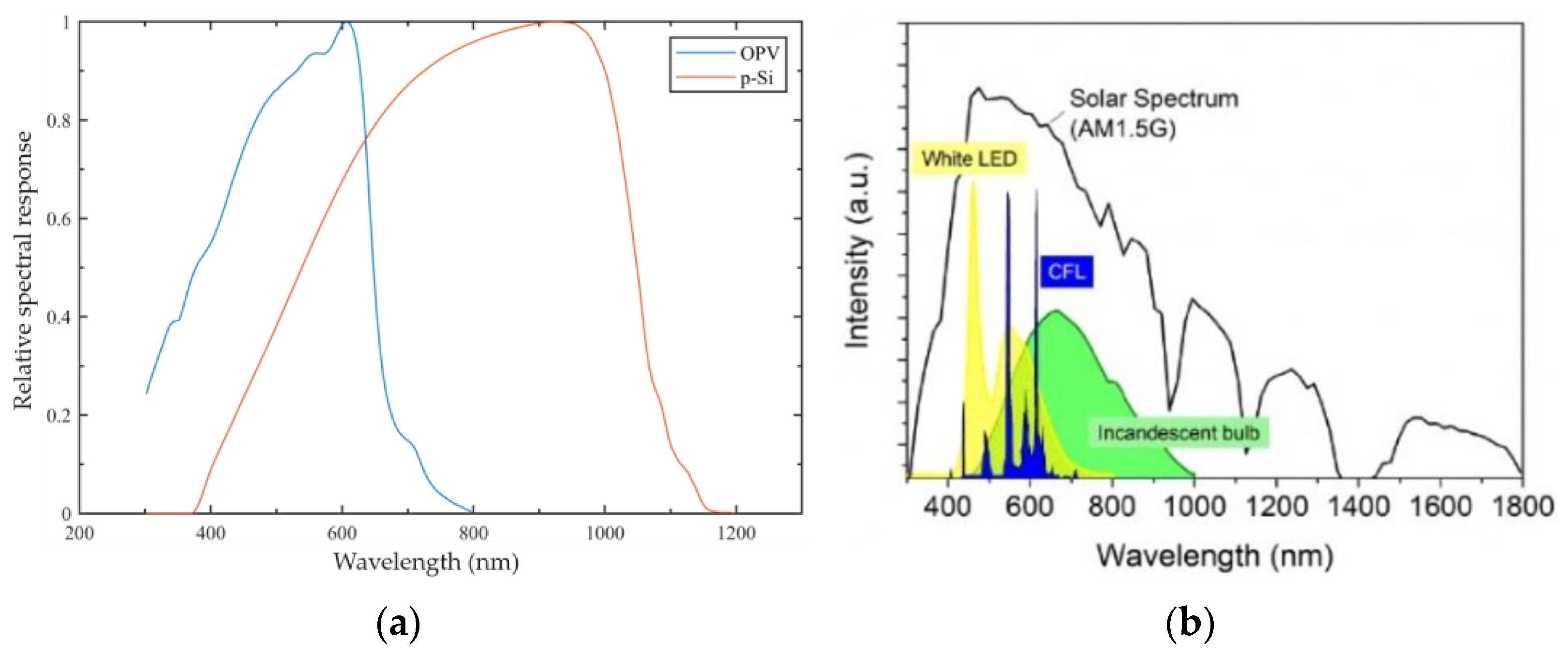
Organic photovoltaic (OPV) film technology stands out here. According to [33], these cells are made up of several organic semiconductor photovoltaic films in series or parallel arrangements, which have characteristics that physically guarantee a diversity of sizes and shapes, and electrically, despite a shorter service life, a higher efficiency, reaching 20% higher than silicon cells for indoor applications.
This efficiency in indoor environments is due to the lighting spectrum in which OPVs perform better when compared to polycrystalline silicon inorganic cell panels, Figure 3a, which is different from the solar lighting spectrum, Figure 3b, in which silicon-based panels perform better.
A UT383BT Mini Light Meter with an accuracy of ±4% plus 8 units was used to measure the lighting in the room. The measurement was taken at the center of each cabinet door in order to generate a panorama of all the intended installation points. The lowest value obtained in the measurement was 250 lux in the bottom row of the cabinet and the highest value was 800 lux in the center of the top row. The most critical case is the one with the lowest illumination, so, as can be seen in Figure 4a, the OPV was installed in the cabinet in the bottom right-hand corner to test the device’s operation.
The output voltage of the OPV used in an indoor environment naturally fluctuates, as it depends on the lighting conditions to which it is subjected, which in this type of environment tend to be variable. In this installation, the environment is illuminated during office hours, which are 12 noon from Monday to Friday. This fact was taken into account when sizing the system and, as a safety measure, a maximum interval of 72 h without light was stipulated, ensuring that even if the system is left in the dark for this length of time, it will remain operational.
The OPV used, Figure 4b, was developed specifically for the application and, according to the manufacturer, it has a V o c voltage of 15 V when the lighting is over 1000 lux and I s c of 1.5 mA. The tests carried out on the lighting range of the cabinets showed a current variation between 354.10 µA and 800.05 µA and a voltage variation between 4.532 V and 8.765 V.
To carry out the second stage, two electronic circuit possibilities were considered for the system solution, both focusing on reduced cost and operational safety. Operating safety is achieved by controlling the voltage on the supercapacitor, which is the critical element of the device. Considering the low voltage supplied by the OPV, the supercapacitor selected was CDA (Zhifengwei Technology, Taichung City, Taiwan)® LIC0813Q3R8206, with 20 F and a nominal voltage of 3.8 V, maximum of 4.2 V, with energy storage of 23 mWh and a maximum discharge current of 500 mA, meeting the needs of the intended load.
OPVs are known for being flexible and cheaper to produce than traditional photovoltaic panels, but their energy conversion efficiency is still relatively low. This means that to generate the same amount of energy as conventional panels, you would need a larger space or more OPV panels, which may not be feasible in all situations, especially in urban areas with limited space.
In addition, very low current and voltage values make it difficult to integrate OPVs with existing power systems, which are generally designed to higher specifications.
Therefore, to overcome these limitations, the first circuit designed was an electronic load to dissipate the excess energy after the supercapacitor’s maximum voltage is reached. It is a simple circuit that uses a transistor as the active element to control the capacitor’s voltage. As the values involved are in the order of µA, the transistor bias circuit was designed with MΩ resistors and the transistor selected was a Darlington type with an Hfe of ten thousand. When the capacitor voltage rises, the transistor’s base current increases, causing it to discharge the capacitor on the resistor used as a load. The model of this simplified circuit can be seen in Figure 5a.
The second circuit considered was a shunt regulator, Figure 5b, which works in a similar way to the previous one by diverting the current when the capacitor voltage reaches the desired value. To ensure minimum consumption of the circuit, the bias resistors are also of the order of MΩ for this model.
In addition to the voltage-limiting circuit on the capacitor, a Schottky diode was added for reverse current protection in the OPV, an auxiliary USB connection charging circuit with current and voltage limiting by Zener diode, protected against reverse current by a Schottky diode as shown in Figure 5c. Schottky diodes were chosen because of the low voltage drop in direct polarization.
With the input circuits defined, it was necessary to implement a PFM-type synchronous boost converter with high conversion efficiency, low power consumption, and high operating frequency. The chip selected was Microone (Nanjing Micro One Elec, Nanjing, China)® ME2188A50PG, which uses a PFM control circuit to automatically change the duty cycle coefficient according to the value of the load current, in order to achieve low ripple, high efficiency, and a wide output voltage range. The chip’s integrated synchronous switching tube and low current consumption effectively improve the efficiency of the DC–DC conversion and the life cycle of the equipment. Only three peripheral components are needed to complete the increase in input voltage to the required operating voltage in the system, Figure 6.
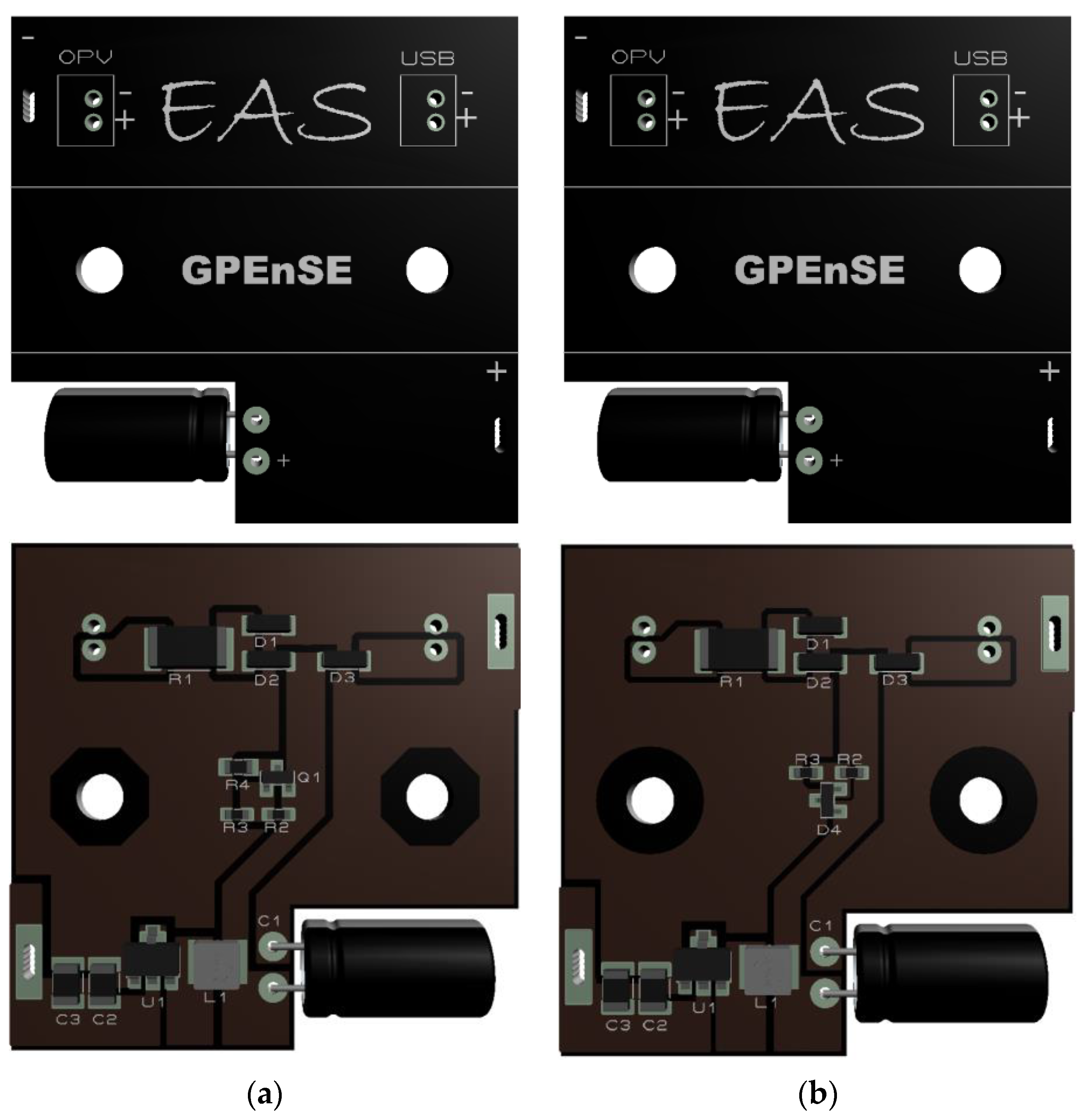
With the schematics defined, two PCB versions were made: Figure 7a shows the supercapacitor voltage control circuit carried out by the transistor and Figure 7b the circuit with the control carried out by the shunt regulator. Both versions have the same layout on the top side of the board. The choice of miniaturized components made it possible to develop the board in dimensions similar to those of a compartment for three AAA batteries.
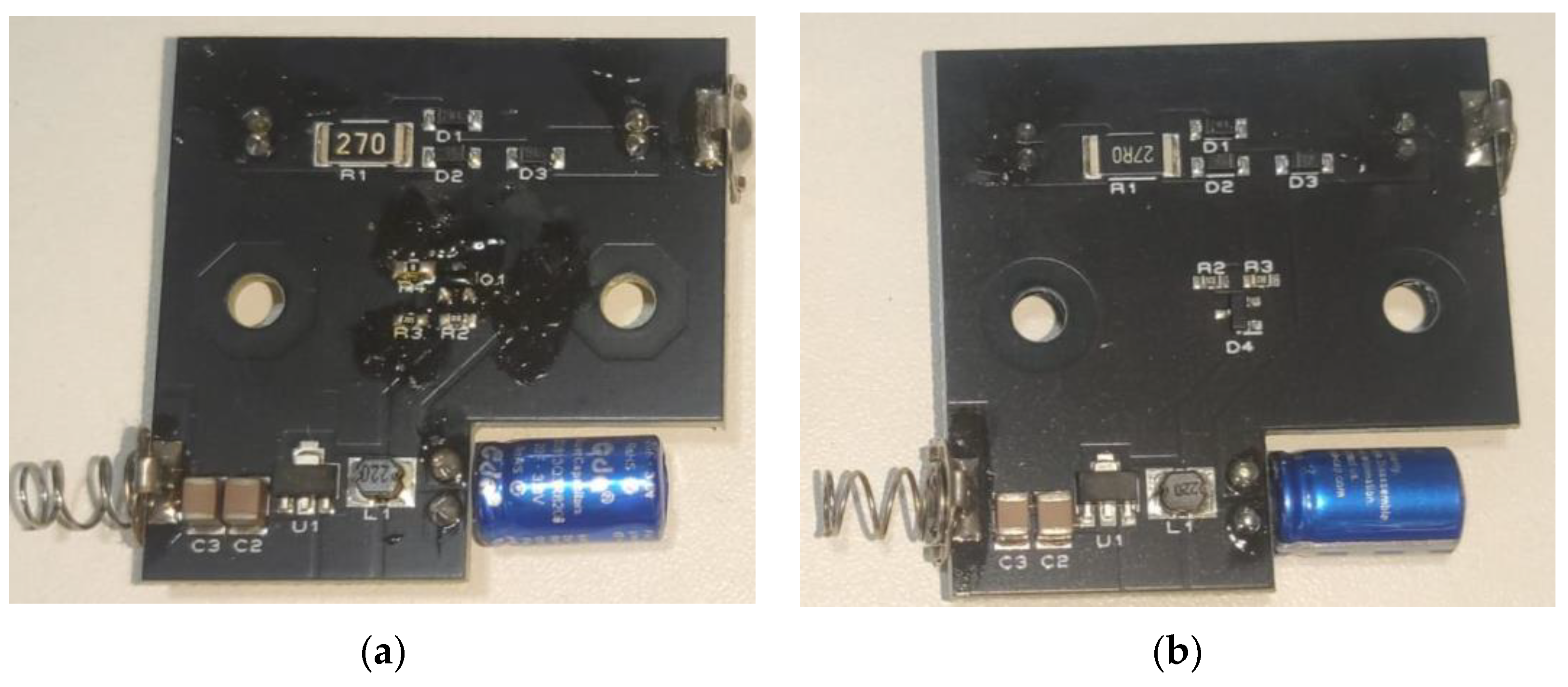
Both models were produced in stage three on 1.6 mm thick 1 Oz glass fiber PCBs, as shown in Figure 8a,b. In addition, the connectors were inserted to facilitate installation and bench testing.
The bench tests consisted of determining the consumption of each part of the system in the voltage operating range of the supercapacitor as reported by the manufacturer, i.e., from 2.5 V to 4.2 V. To do this, nine measurements were made between 2.6 V and 4.2 V with a 200 mV step in both circuits. In the case of the circuit with the electronic load, the current in the load resistor was measured, and in the case of the shunt regulator circuit, the current in the anode of the shunt regulator was measured. The consumption of the boost converter over the entire range was also measured and the results will be discussed in the next section.

4. Results

In both circuits, the boost converter had a stable consumption of 17.05 µA over the entire voltage range of the supercapacitor and kept the output regulated and without oscillation in order to keep the lock operating normally.
The circuit with the electronic load showed the values indicated in Table 3 and the circuit with the shunt regulator showed consumption of 35.01 µA over the entire voltage range of the supercapacitor.
In line with the supercapacitor manufacturer’s recommendation, the 5.0 V USB connection auxiliary charging circuit with a 3.6 V Zener diode current and voltage limiter was also tested and, as a result, a maximum charging current of 51.85 mA was obtained, operating at almost half the maximum limit. This circuit is used when the system is installed to charge the capacitor for the first time, in the event of a long period without exposure to light or in the event of a fault to enable the lock to be activated.
The circuits were mounted one at a time in the cabinet, as shown in the illustration above, during a test period of 30 days for each circuit. The electronic lock was used four times a day from Monday to Friday, at the beginning and end of each shift. In both circuits, the lighting activation metric was maintained for a period of 12 h a day.
At the start of the test on each circuit, the supercapacitor was charged to the capacitor’s nominal operating voltage using the auxiliary charging connection, and the installations were carried out at the beginning of the week just before the start of the first daily shift.
The operation was observed daily, but without intervention with the devices, precisely to validate their use in real application conditions. On the twenty-second day, the circuit with the electronic load failed to open the lock at the start of the first shift, requiring a recharge of the supercapacitor auxiliary, at which point the capacitor voltage was 1.823 V.
The same usage metric was applied to the shunt regulator circuit and no intervention was required during the 30 days. At the end of the last shift on day 30, the voltage measurement on the capacitor was carried out and the value obtained was 3.789 V, i.e., the capacitor was charged to its nominal operating voltage, validating the effectiveness of the circuit developed.
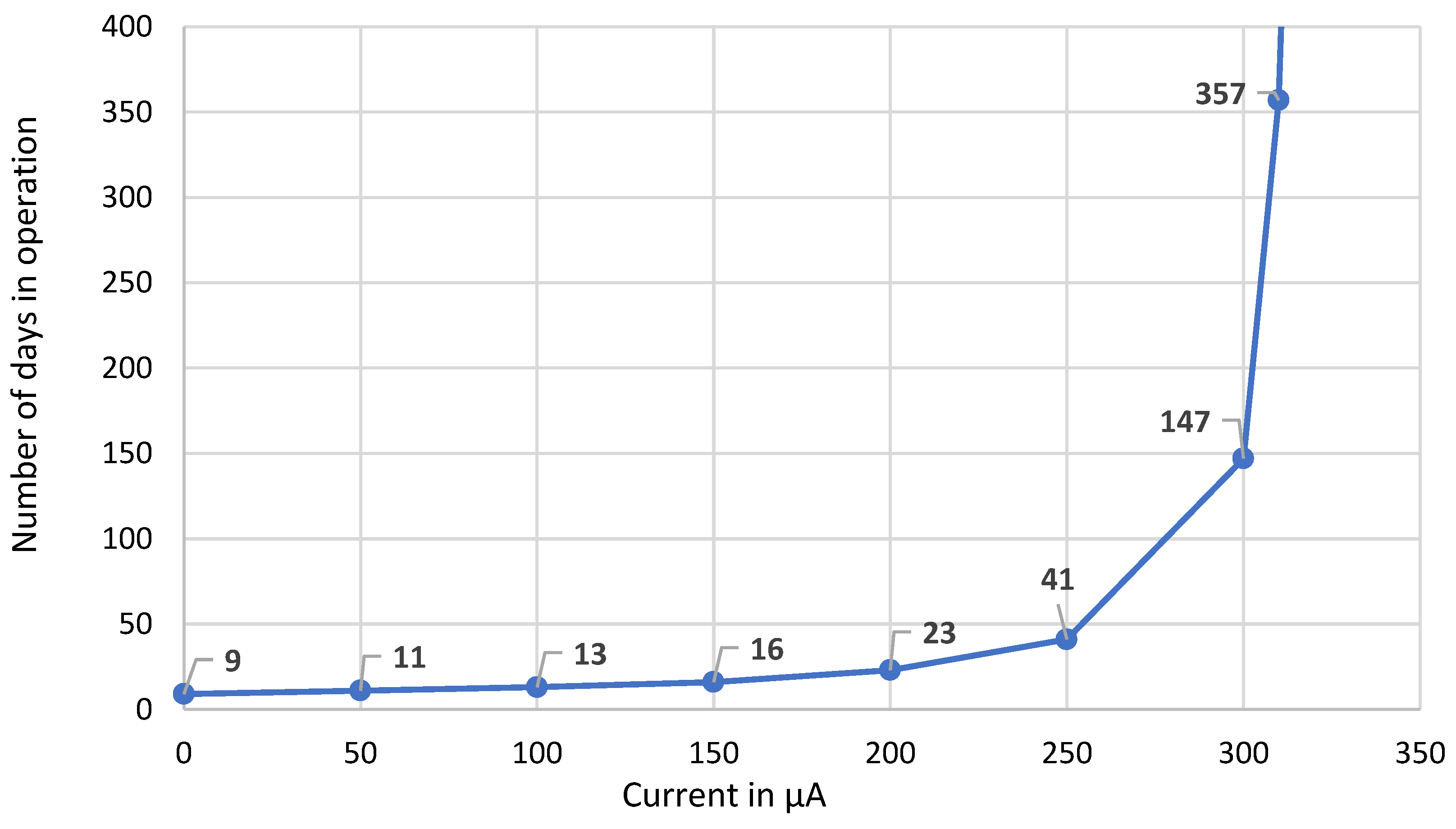
After this test, situations with lower lighting values were simulated, in which the current supplied by the OPV was reduced by 50 µA per simulation, generating the graph shown in Figure 9, which represents the relationship between the current supplied by the OPV and the number of days that the system would continue to operate while maintaining the consumption pattern of the situation previously presented.
Without the OPV supply, and with the supercapacitor fully charged, the system operates for eight days and shows energy insufficiency on day nine. With the OPV supplying 200 µA, the system operates for 22 days and shows energy insufficiency on day 23, while with 310 µA the system expands its operating capacity to three hundred and 57 days and from 320 µA the system is self-sufficient. It is worth noting that to supply 350 µA to this system requires approximately 250 lux.

5. Discussion

Considering that the validation of the self-powered lock in terms of its operational age took place in a scheme that guaranteed the availability of light provided by a real scenario and made it possible to validate its energy quantities, in order to analyze the behavior of both the charging and discharging cycles of the circuits and their self-sufficiency over time. And, as mentioned in Section 3, the system was installed in the most critical case, where the illumination level was 250 lux. The result presented in the circuit tests is justifiable due to the difference in efficiency of each one.
According to the results presented, with the supercapacitor at 3800 V, the electronic load circuit consumes 75.20 µA and circuit two only 35.01 µA, i.e., less than half the consumption and, considering that both the load and the converter used maintain the same consumption in both applications, the OPV necessarily needs to deliver more energy for the circuit with the electronic load to remain operational, so the lighting would need to be higher than 250 lux.
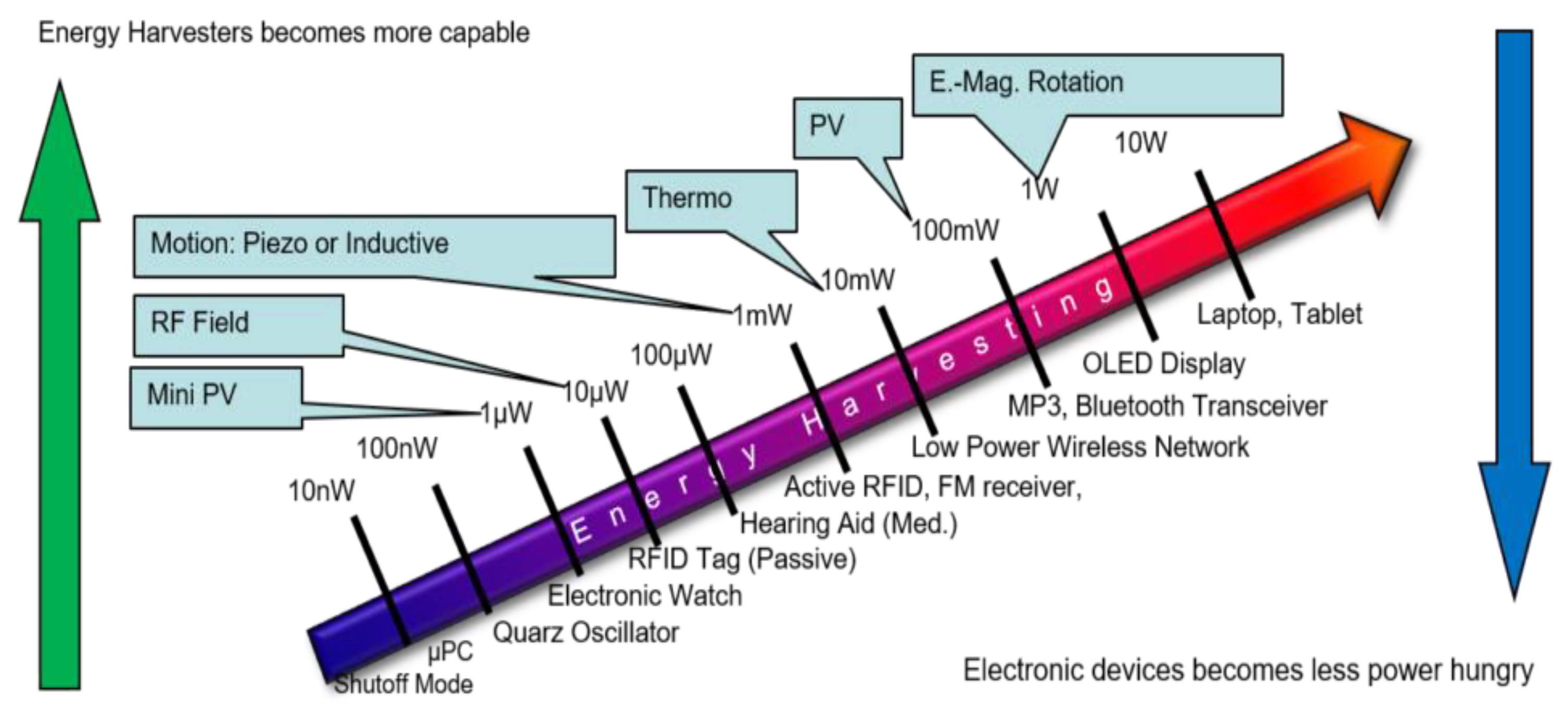
The minimum illuminance levels for interiors, as per international standards, vary based on the type of environment and activities conducted. For instance, in offices and administrative areas, the recommended illuminance levels typically range from 500 to 1000 lux, ensuring visual comfort, safety, and operational efficiency within indoor spaces. Thus, achieving a minimum of 250 lux is feasible in standard indoor settings. The device created has a broad range of applications, suitable for all loads under 1 W. Figure 10 illustrates various potential applications based on power consumption, highlighting the system’s versatility across scenarios such as sensor node networks and home automation devices [36].
Knowing that the amount of accumulated load is equal to the current multiplied by the time, it is possible to calculate the amount of accumulated load over a twelve-hour period and use this value to analyze the weekly accumulation of load, discounting the daily consumption of the lock’s drives.
The sum of the consumption current of the lock on standby with the consumption of the inverter and the shunt regulator circuit is 89.06 µA, giving a total daily consumption of 7.69 C and minimum generation in 12 h for a current of 350.00 µA totals 15.12 C, which results in a daily surplus of 7.42 C. Removing the consumption of the lock’s four daily actuations leaves 3.24 C of charge, thus keeping the capacitor charged. With the same conditions for circuit one, the daily load deficit is 0.23 C.
This analysis shows the system’s consumption agents (Figure 11). The highest consumption is due to the four drives of the electronic lock (35%), followed by standby consumption (27%), almost the same value as the shunt regulator (26%) and supplemented by the 12% of the boost converter (12%).
In view of the autonomy results and the configuration of the tests carried out, the application of the Self-Powered lock with OPV is recommended in environments with an illuminance level above 250 lux, provided that the values presented in Table 4 characterizing the operability and energy sufficiency of the system used are observed.

6. Conclusions

The aim of this work was to investigate and test techniques and materials for the application of self-sufficient energy systems indoors, with integration into a commercial electronic lock. Initially, a systematic literature review was carried out using the Proknow-C methodology, resulting in a bibliographic portfolio with 30 relevant articles on the subject, but none of them addressed an implementation for integrating the OPV into this type of equipment.
Next, two circuits were developed to integrate the OPV with the supercapacitor and a commercial load. Based on bench tests, it was possible to create a device that connects the OPV to the supercapacitor, obtaining satisfactory results for the operational functioning of the system in real scenarios.
To assess the system’s energy self-sufficiency, an implementation was carried out in an application scenario and the system was tested over 30 days to analyze its performance. The results obtained proved the viability and effectiveness of the system. With a minimum daily illuminance of 250 lux for 12 h, for self-sufficient operation. With the results obtained, it can be concluded that the range of applications for the device created is very wide, making it suitable for all loads under 1 W. Mainly sensor node networks and home automation devices.
Finally, the successful implementation of this system opens up opportunities for its expansion and application in other electronic devices with similar characteristics in terms of energy consumption and storage. This makes it possible to use this approach in various contexts, broadening its potential impact and promoting energy efficiency in various applications, resulting in the patent application [37].

Author Contributions

Conceptualization: E.A.d.S., W.M.C.F., M.R.C. and O.H.A.J.; methodology: E.A.d.S., W.M.C.F. and O.H.A.J.; validation: E.A.d.S. and O.H.A.J.; investigation and simulation: E.A.d.S., W.M.C.F. and O.H.A.J.; writing—original draft preparation: E.A.d.S., W.M.C.F., M.R.C. and O.H.A.J.; writing—review and editing: E.A.d.S. and O.H.A.J.; project administration E.A.d.S. and O.H.A.J.; funding acquisition: M.R.C. and O.H.A.J. All authors have read and agreed to the published version of the manuscript.

Funding

This research was partially supported by the FACEPE agency (Fundação de Amparo a Pesquisa de Pernambuco) throughout the project with references APQ-0616-9.25/21 and APQ-0642-9.25/22. O.H.A.J. was funded by the Brazilian National Council for Scientific and Technological Development (CNPq), grant numbers 407531/2018-1, 303293/2020-9, 405385/2022-6, 405350/2022-8 and 40666/2022-3, as well as the Program in Energy Systems Engineering (PPGESE) Academic Unit of Cabo de Santo Agostinho (UACSA), Federal Rural University of Pernambuco (UFRPE). M.H.M.B. and F.M.O. were funded by the Federal University of Latin American Integration (UNILA). M.R.C. was funded by UNICAMP (State University of Campinas) throughout the Auxílio Início de Carreira (Docente), FAEPEX, process number 2095/23, as well as the Programa de Incentivo a Novos Docentes (PIND), FAEPEX, process number 2419/23.

Data Availability Statement

Data are contained within the article.

Conflicts of Interest

The authors declare no conflict of interest.

References

  1. Sutikno, T.; Aprilianto, R.A.; Purnama, E.H.S. Application of non-isolated bidirectional DC–DC converters for renewable and sustainable energy systems: A Review. Clean Energy 2023, 7, 293–311. [Google Scholar] [CrossRef]
  2. Kaushalya, T.; Littow, M.; Virta, E.; Ruotsalainen, T.; Juuti, J.; Bai, E.Y. Evaluation of charging efficiency for power management integrated circuits and their compatibility with indoor light energy harvesting devices for IOT sensors. SSRN, 2023; preprint. [Google Scholar] [CrossRef]
  3. Mohamad-Saleh, W.-H.T.E.J. Critical review on interrelationship of electro-devices in PV solar systems with their evolution and future prospects for MPPT applications. Energies 2023, 16, 850. [Google Scholar] [CrossRef]
  4. Bito, J.; Hester, J.G.; Tentzeris, M.M. A fully autonomous ultra-low power hybrid RF/Photovoltaic energy harvesting system with −25 dbm sensitivity. In Proceedings of the 2017 IEEE Wireless Power Transfer Conference (WPTC), Taipei, Taiwan, 10–12 May 2017; pp. 1–4. [Google Scholar] [CrossRef]
  5. Jung, S.; Oh, J.; Yang, U.J.; Lee, S.M.; Lee, J.; Jeong, M.; Cho, Y.; Kim, S.; Baik, J.M.; Yang, C. 3D Cu ball-based hybrid triboelectric nanogenerator with non-fullerene organic photovoltaic cells for self-powering indoor electronics. Nano Energy 2020, 77, 105271. [Google Scholar] [CrossRef]
  6. Maciel, J.N.; Ledesma, J.J.G.; Ando Junior, O.H. Forecasting solar power output generation: A systematic review with the ProKnow-C. IEEE Lat. Am. Trans. 2021, 19, 612–624. [Google Scholar] [CrossRef]
  7. Ensslin, S.R.; Ensslin, L.; Yamakawa, E.K.; Nagaoka, M.P.T.; Aoki, A.R.; Siebert, L.C. Processo estruturado de revisão da literatura e análise bibliométrica sobre avaliação de desempenho de processos de implementação de eficiência energética. Rev. Bras. Energ. 2014, 20, 21–50. [Google Scholar]
  8. Sher, H.A.; Murtaza, A.F.; Noman, A.; Addoweesh, K.E.; Al-Haddad, K.; Chiaberge, M. A new sensorless hybrid mppt algorithm based on fractional short-circuit current measurement and P&O MPPT. IEEE Trans. Sustain. Energy 2015, 6, 1426–1434. [Google Scholar] [CrossRef]
  9. Tang, X.; Wang, X.; Cattley, R.; Gu, F.; Ball, E.A. Energy harvesting technologies for achieving self-powered wireless sensor networks in machine condition monitoring: A Review. Sensors 2018, 18, 4113. [Google Scholar] [CrossRef]
  10. Liu, R.; Takakuwa, M.; Li, A.; Inoue, D.; Hashizume, D.; Yu, K.; Umezu, S.; Fukuda, K.; Someya, T. An efficient ultra-flexible photo-charging system integrating organic photovoltaics and supercapacitors. Adv. Energy Mater. 2020, 10, 2000523. [Google Scholar] [CrossRef]
  11. Singh, R.; Shin, S.C.; Lee, H.; Kim, M.; Shim, J.W.; Cho, K.; Lee, J.J. ternary blend strategy for achieving high-efficiency organic photovoltaic devices for indoor applications. Chem. Eur. J. 2019, 25, 6154–6161. [Google Scholar] [CrossRef]
  12. Satharasinghe, A.; Hughes-Riley, T.; Dias, T. A review of solar energy harvesting electronic textiles. Sensors 2020, 20, 5938. [Google Scholar] [CrossRef]
  13. Tang, Y.; Li, X.; Lv, H.; Wang, W.; Zhi, C.; Li, E.H. Integration designs toward new-generation wearable energy supply-sensor systems for real-time health monitoring: A Minireview. InfoMat 2020, 2, 1109–1130. [Google Scholar] [CrossRef]
  14. Patra, A.; Namsheer, K.; Jose, J.R.; Sahoo, S.; Chakraborty, B.; Rout, C.S. Understanding the charge storage mechanism of supercapacitors: In situ/operando spectroscopic approaches and theoretical investigations. J. Mater. Chem. A 2021, 9, 25852–25891. [Google Scholar] [CrossRef]
  15. Grossi, M. Energy harvesting strategies for wireless sensor networks and mobile devices: A Review. Electronics 2021, 10, 661. [Google Scholar] [CrossRef]
  16. Takshi, A.; Aljafari, B.; Kareri, T.; Stefanakos, E. A critical review on the voltage requirement in hybrid cells with solar energy harvesting and energy storage capability. Batter. Supercaps 2021, 4, 252–267. [Google Scholar] [CrossRef]
  17. AAbdelnour, A.; Hallet, A.; Dkhil, S.B.; Pierron, P.; Kaddour, D.; Tedjini, S. Energy harvesting based on printed organic photovoltaic cells for RFID applications. In Proceedings of the 2019 IEEE International Conference on RFID Technology and Applications (Rfid-Ta), Pisa, Italy, 25–27 September 2019; pp. 110–112. [Google Scholar] [CrossRef]
  18. Batista, D.; Oliveira, L.B.; Paulino, N.; Carvalho, C.; Oliveira, J.P.; Farinhas, J.; Charas, A.; dos Santos, P.M. Combined organic photovoltaic cells and ultra low power CMOS circuit for indoor light energy harvesting. Sensors 2019, 19, 1803. [Google Scholar] [CrossRef]
  19. Nordin, N.A.; Ansari, M.N.M.; Nomanbhay, S.M.; Hamid, N.A.; Tan, N.M.; Yahya, Z.; Abdullah, I. Integrating photovoltaic (PV) solar cells and supercapacitors for sustainable energy devices: A Review. Energies 2021, 14, 7211. [Google Scholar] [CrossRef]
  20. Zhang, S.; Bristow, N.; David, T.W.; Elliott, F.; O’mahony, J.; Kettle, E.J. Development of an organic photovoltaic energy harvesting system for wireless sensor networks; application to autonomous building information management systems and optimisation of OPV module sizes for future applications. Sol. Energy Mater. Sol. Cells 2022, 236, 111550. [Google Scholar] [CrossRef]
  21. Takshi, A.; Tevi, T.; Rahimi, F. Organic photovoltaic devices with concurrent solar energy harvesting and charge storage capability. In Proceedings of the SPIE Optics + Photonics for Sustainable Energy, San Diego, CA, USA, 9–13 August 2015; Volume 9562. [Google Scholar] [CrossRef]
  22. Iwan, A.; Pellowski, W.; Bogdanowicz, K.A. Conversion of radiophotoluminescence irradiation into electricity in photovoltaic cells. A review of theoretical considerations and practical solutions. Energies 2021, 14, 6186. [Google Scholar] [CrossRef]
  23. Rahman, M.S.; Chakravarty, U.K. A hybrid energy harvesting system based on solar radiation and mechanical vibration. In Volume 1: Advances in Aerospace Technology; American Society of Mechanical Engineers: Pittsburgh, PA, USA, 2018; p. V001t03a017. [Google Scholar] [CrossRef]
  24. Lavanya, A.; Navamani, J.D.; Vijayakumar, K. Performance analysis of triple port dc-dc converter for energy harvesting systems. In Proceedings of the 11th National Conference on Mathematical Techniques and Applications, Chennai, India, 11–12 January 2019; p. 020012. [Google Scholar] [CrossRef]
  25. Lupo, D.; Keskinen, J.; Taavela, J.; Sirén, H.; Virtanen, J.; Mäntysalo, M. Flexible Temperature Logger Powered by Solar Cell and Supercapacitor. Poster Session Presented at innoLAE 2019, Cambridge, UK. 2019. Available online: https://researchportal.tuni.fi/en/publications/flexible-temperature-logger-powered-by-solar-cell-and-supercapaci (accessed on 20 May 2024).
  26. Biswas, S.; Lee, Y.; Kim, H. Micropower energy harvesting using high-efficiency indoor organic photovoltaics for self-powered sensor systems. J. Sens. Sci. Technol. 2021, 30, 364–368. [Google Scholar] [CrossRef]
  27. MArvani, M.; Keskinen, J.; Mansfeld, S.; Railanmaa, A.; Rokaya, C.; Lupo, D.; Hiltunen, A.; Vivo, P. Flexible energy supply for distributed electronics powered by organic solar cell and printed supercapacitor. In Proceedings of the 2020 IEEE 20th International Conference on Nanotechnology (IEEE-NANO), Montreal, QC, Canada, 29–31 July 2020; pp. 257–262. [Google Scholar] [CrossRef]
  28. Mashali, S.; Varjani, A.Y. Dual-Input, Single-Output Step-Up Dc/Dc power electronic interface for energy harvesting systems. In Proceedings of the 2023 14th Power Electronics, Drive Systems, and Technologies Conference (PEDSTC), Babol, Iran, 31 January–2 February 2023; pp. 1–5. [Google Scholar] [CrossRef]
  29. Oliveira, F.M.; Mariano, A.C.S.; Salvadori, F.; Ando Junior, O.H. Power management and power quality system applied in a single-phase nanogrid. Energies 2022, 15, 7121. [Google Scholar] [CrossRef]
  30. Kim, W.; Cho, K.; Lee, J.; Ko, D.; Jung, E.S. An indoor light-powered sensor system integrated with organic photovoltaics. Adv. Mater. Technol. 2023, 8, 2202040. [Google Scholar] [CrossRef]
  31. Dimitriev, O.P. Thermomechanical energy converters for harvesting thermal energy: A Review. J. Renew. Mater. 2023, 11, 1555–1600. [Google Scholar] [CrossRef]
  32. Poulek, V.; Dang, M.-Q.; Libra, M.; Beránek, V.; Safránková, J. PV panel with integrated lithium accumulators for BAPV applications—One year thermal evaluation. IEEE J. Photovolt. 2020, 10, 150–152. [Google Scholar] [CrossRef]
  33. Izidoro, C.L.; Chaves Filho, W.M.; Cavallari, M.R.; Ando Junior, O.H. Organic Photovoltaic (OPV) with electronic protection system: A systematic review. Braz. Arch. Biol. Technol. 2024, 67, e24230786. [Google Scholar] [CrossRef]
  34. Neves, L.A.; Leite, G.C.; by Paula Vieira, K.C.; MacKenzie, R.; Porto, M.P. Analysis of the performance of organic and inorganic photovoltaic cells under different air masses using numerical simulation. In Proceedings of the VIII Brazilian Congress of Solar Energy, Fortaleza, Brazil, 1–5 June 2020. [Google Scholar]
  35. Kjellby, R.A.; Johnsrud, T.E.; Loetveit, S.E.; Cenkeramaddi, L.R.; Hamid, M.; Beferull-Lozano, B. Self-Powered IoT device for indoor applications. In Proceedings of the 31th International Conference on VLSI Design and 17th International Conference on Embedded Systems, Pune, India, 6–10 January 2018. [Google Scholar]
  36. Foelkel, L. Energy Harvesting is not Fiction Anymore. In Proceedings of the 2nd PCNS, Bucharest, Romania, 10–13 September 2019. [Google Scholar]
  37. Ando Junior, O.H.; Chaves Filho, W.M.; Silva, E.A.D. System for Conditioning, Feeding, Storing, and Managing Energy for Sensors and/or Electronic Devices Self-Powered by Photovoltaic Cell; BR1020240088069; National Institute of Industrial Property (INPI): Rio de Janeiro, Brazil, 2024. [Google Scholar]
Figure 1. Simplified Diagram of the Self-Powered OPV System.
Electronics 13 02518 g001
Figure 2. Diagram of project development stages.
Electronics 13 02518 g002
Figure 3. Demonstrated (a) OPV and poly-Si relative spectral response [34] and (b) Spectrum of different light sources [35].
Electronics 13 02518 g003
Figure 4. Demonstrated (a) Cabinet with electronic locks and (b) Self-powered development with organic photovoltaic.
Electronics 13 02518 g004
Figure 5. Diagrams of (a) the electronic load, (b) the shunt regulator and (c) the input protection circuit.
Electronics 13 02518 g005
Figure 6. Boost converter diagram.
Electronics 13 02518 g006
Figure 7. Electronic load circuit layout (a) and shunt regulator circuit layout (b).
Electronics 13 02518 g007
Figure 8. Demonstrated (a) PCB circuit with electronic load and (b) PCB shunt regulator circuit.
Electronics 13 02518 g008
Figure 9. Relationship between current supplied by the OPV and days in operation.
Electronics 13 02518 g009
Figure 10. Energy harvesting resources versus requirements [36].
Electronics 13 02518 g010
Figure 11. Daily load consumption of the components, in relation to the total load consumed by the system per day.
Electronics 13 02518 g011
Table 1. Definition of key words and combinations.
Searched CombinationsScopusWoSGS
“Organic Photovoltaic” AND “Supercapacitor”3517200
“Organic Photovoltaic” AND “Buck-Boost”1254102
“Organic Photovoltaic” AND “Self-Powered”8015200
Total paper24036502
Raw Paper Base778
Table 2. Research in Scientific Databases.
Repository CCit.Ref.
A new senseless hybrid MPPT algorithm based on fractional short-circuit current measurement and P&O MPPT384[8]
Energy harvesting technologies for achieving self-powered wireless sensor networks in machine condition monitoring: A review181[9]
An efficient ultra-flexible photo-charging system integrating organic photovoltaics and supercapacitors61[10]
Ternary Blend Strategy for Achieving High-Efficiency Organic Photovoltaic Devices for Indoor Applications34[11]
A review of solar energy harvesting electronic textiles33[12]
Integration designs toward new-generation wearable energy supply-sensor systems for real-time health monitoring: A minireview32[13]
Understanding the charge storage mechanism of supercapacitors: in situ/operando spectroscopic approaches and theoretical investigations30[14]
Energy harvesting strategies for wireless sensor networks and mobile devices: A review.25[15]
A Critical Review On The Voltage Requirement In Hybrid Cells With Solar Energy Harvesting And Energy Storage Capability15[16]
Energy harvesting based on printed organic photovoltaic cells for RFID applications9[17]
Combined organic photovoltaic cells and ultra-low power CMOS circuit for indoor light energy harvesting9[18]
Integrating Photovoltaic (PV) solar cells and supercapacitors for sustainable energy devices: A review8[19]
A fully autonomous ultra-low power hybrid RF/photovoltaic energy harvesting system with −25 dBm sensitivity6[4]
Development of an organic photovoltaic energy harvesting system for wireless5[20]
Organic photovoltaic devices with concurrent solar energy harvesting and charge storage capability5[21]
Conversion of radiophotoluminescence irradiation into electricity in photovoltaic cells. A review of theoretical considerations and practical solutions4[22]
a hybrid energy harvesting system based on solar radiation and mechanical vibration3[23]
performance analysis of triple port DC–DC converter for energy harvesting systems2[24]
critical review on interrelationship of electro-devices in PV solar systems with their evolution and future prospects for MPPT applications2[3]
Flexible temperature logger powered by solar cell and supercapacitor1[25]
Micropower energy harvesting using high-efficiency indoor organic photovoltaics for self-powered sensor systems1[26]
Flexible energy supply for distributed electronics powered by organic solar cell and printed supercapacitor0[27]
Dual-Input, Single-Output Step-Up DC/DC power electronic interface for energy harvesting systems0[28]
Application of non-isolated bidirectional DC–DC converters for renewable and sustainable energy systems: a review0[1]
Evaluation of charging efficiency for power management integrated circuits and their compatibility with indoor light energy harvesting devices for IoT sensors0[2]
Power management and power quality system applied in a single-phase nanogrid0[29]
An indoor light-powered sensor system integrated with organic photovoltaics0[30]
Thermomechanical energy converters for harvesting thermal energy: A review0[31]
Table 3. Electronic load consumption.
Voltage (V)Current in R4 (µA)
4.20525.00
4.00209.00
3.8075.20
3.6025.10
3.407.94
3.202.42
3.000.72
2.800.21
2.600.08
Table 4. Characterization of the System’s Operability and Energy Sufficiency.
Operating SpecificationsValue
Maximum capacitor voltage [V]:4.20
Minimum capacitor voltage [V]:2.50
Maximum time without recharging [h]:72.00
Charging time per day [h]:12.00
Interval between recharging [h]:12.00
Minimum charging current [µA]:350.00
Capacitance [F]:20.00
Standby load consumption [µA]:37.00
Load consumption under normal conditions [mA]69.70
Number of operations between recharge intervals:4.00
Amount of load accumulated per day [C]:15.12
Amount of standby charge consumed in 24 h [C]:7.69
Recharge surplus per day [C]:3.24
Disclaimer/Publisher’s Note: The statements, opinions and data contained in all publications are solely those of the individual author(s) and contributor(s) and not of MDPI and/or the editor(s). MDPI and/or the editor(s) disclaim responsibility for any injury to people or property resulting from any ideas, methods, instructions or products referred to in the content.