Article

High-Capacity Multiple-Input Multiple-Output Communication for Internet-of-Things Applications Using 3D Steering Nolen Beamforming Array †

College of Engineering, Florida A&M University, Tallahassee, FL 32310, USA
*
Author to whom correspondence should be addressed.
This paper is an extended version of our paper published in 2022 IEEE International Symposium on Phased Array Systems & Technology under the title “Full 3D Coverage Beamforming Phased Array with Reduced Phase Shifters and Control 2D Tunable 3 × 3 Nolen Matrix”.
Electronics 2024, 13(13), 2452; https://doi.org/10.3390/electronics13132452
Submission received: 12 May 2024 / Revised: 14 June 2024 / Accepted: 17 June 2024 / Published: 22 June 2024
(This article belongs to the Special Issue Advances in Wireless Communication for loT)

Abstract

:
In this paper, a novel 2D Nolen beamforming phased array with 3D scanning capability to achieve high channel capacity is presented for multiple-input multiple-output (MIMO) Internet-of-Things (IoT) applications. The proposed 2D beamforming phased array is designed by stacking a fundamental building block consisting of a 3 × 3 tunable Nolen matrix, which applies a small number of phase shifters with a small tunning range and reduces the complexity of the beam-steering control mechanism. Each 3 × 3 tunable Nolen matrix can achieve a full 360° range of progressive phase delay by exciting all three input ports, and nine individual radiation beams can be generated and continuously steered on azimuth and elevation planes by stacking up three tunable Nolen matrix in horizontal and three in vertical to maximize signal-to-noise ratio (SNR) in the corresponding spatial directions. To validate the proposed design, the simulations have been conducted on the circuit network and assessed in a fading channel environment. The simulation results agree well with the theoretical analysis, which demonstrates the capability of the proposed 2D Nolen beamforming phased array to realize high channel capacity in MIMO-enabled IoT communications.

1. Introduction

The emerging 5G/NextG and Wi-Fi 6E/7 have revolutionized wireless communication technology, and they feature high channel capacity, reduced transmission latency, and reduced network congestion. With the new wide instantaneous band spectrum, a novel architectural radio access network, improvements in channel model estimation and physical layer technologies, smart antenna design, beamforming algorithms, and massive multiple-input-multiple-output (MIMO) techniques are investigated to meet a high standard requirement in the upgraded Internet-of-Things (IoT) network [1,2,3]. Specifically, in comparison with conventional single-input single-output and single-input multiple-output (SIMO or MISO) systems, the MIMO technique significantly improves the channel capacity to satisfy the demand for high data rate transmission, and it is widely applied in IoT applications, including smart transportation, smart healthcare, smart industry, and smart cities [4,5]. To further enhance the selection diversity capacity and maximize the spatial efficiency and channel signal-to-noise ratio (SNR), the beamforming technique is developed in an MIMO system as a useful pre-coding approach [6,7]. Digital beamforming, local oscillator phase shifting, and RF phase shifting are the primary techniques used to realize beamforming in the MIMO system, where the radiation beam formed from an antenna array system can be continuously steered to the desired direction. Unlike other beamforming methods, in the RF phase shifting technique, controlling the signal phase and magnitude for radiating antenna elements is crucial to manipulating the spatial angle of beamforming, and several methods have been investigated, such as parallel feeding [8,9], series feeding [10,11], and matrix feeding [12,13,14], to control the signal phase and magnitude. Compared with the other two, the matrix feeding network is composed of couplers, phase shifters, crossover, and a power splitter, which performs as a spatially fast Fourier transform to radiate up to N orthogonal directive beams combined with a uniform linear antenna array. More specifically, the Butler matrix is one of the most well-known feeding networks, and it has been intensively investigated in terms of symmetrical or unsymmetrical topology with different scales in [15,16] and tuning capability in [17,18]. With the increasing number of antenna elements in an RF beamforming phased array, the RF front-end needs to integrate a smaller number of passive components, such as a coupler, crossover, delay line, and phase shifter, in the feeding network to minimize power loss and simplify the system topology, especially for mm-wave and THz communications. Compared with other feeding networks, the Nolen matrix is composed of fewer circuit components, resulting in low power loss, compact size, and flexibility to generate an arbitrary number of radiation beams, which is an optimum candidate for large-scale RF beamforming phased arrays. In a previous study [19], the Nolen matrix was investigated to generate flexible beams and reduce their size. However, all of them focused on fixed radiation beams without any scanning capabilities, which limits the spatial diversity and efficiency of MIMO systems.
In this paper, a novel 2D tunable Nolen matrix, as shown in Figure 1, has been proposed to generate and steer radiation beams in a full 3D spatial domain for next-generation spatial and beam–space multiplexing wireless applications. The proposed 3D beamforming Nolen phased array features are as follows: (1) flexible progressive phase difference in horizontal and vertical antenna arrays; (2) phase shifters with a small tuning range (120°) are used to realize full 360° progressive phase difference in two planes; (3) only two-channel voltages are applied to concurrently control beam steering; and (4) 3D cubic space coverage enables further enhancement of system channel capacity.
The work in this paper is an extension of our previous publication [20]. The major new contributions to this paper are as follows:
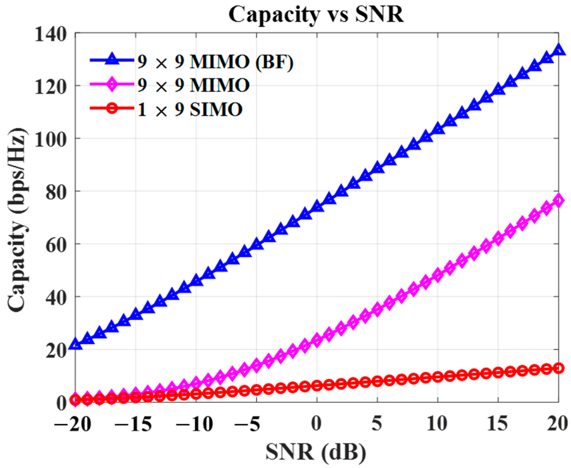
  • A 3D beamforming MIMO system is established based on the 2D Nolen matrix phased array, including modeling of the communication channel and Nolen matrix network. Then, its capability of enhancing channel capacity has been demonstrated.
  • The advancements of the proposed 3 × 3 tunable Nolen matrix are more deeply discussed and compared to other works on tunable beamforming networks.

2. Design Theory and Analysis

The proposed 3D beamforming MIMO communication is depicted in Figure 1, where a novel tunable Nolen matrix beamforming phased array is applied both on the transmitter and receiver sides with a nine-element antenna array. Each of them is designed by stacking three tunable Nolen matrices in the y axis and another three along the x axis. Applying signals at one port, the equal magnitude and progressive phase delay (βx, βy) in two dimensions are generated fed into the nine-element antenna array to generate radiation beams in the cubical 3D space. Nine unique radiation beams pointing in the corresponding cubic sectors can be generated by switching different input ports. Furthermore, to fully cover the 3D space in each sector or steer the beam in any direction, two-channel voltages are applied to configure all of the phase shifters embedded in the Nolen matrix that simultaneously generate progressive phase differences (βx, βy) within the 360° range at their output ports.

2.1. Model of the Proposed 3D MIMO System

Our proposed MIMO system is composed of a receiving diversity scheme, with nine transmitting antennas (NT = 9) and nine receiving antennas (NR = 9). Assuming the channel fades at each receiving branch is frequency nonselective and slowly changes, then the received signal at the individual diversity branch is modeled as follows:
r i , k = h i , k s + n i , k
where {i, k|1 ≤ i, kNR}, s is the transmitted signal, H = [h1,1, …, hi,k] is the channel coefficient, and n = [n1,1, …, ni,k] is the additive white Gaussian noise with identical power spectral density per dimension. If two 2D Nolen matrixes with the transfer functions BT and BR (BT = BR = B) are inserted to feed the antenna elements at each side, the received signal at the diversity branch (i, k) can be given as follows:
r i , k = h i , k * s + n i , k *
where h i , k * and n i , k * are effective vectors of channel and noise matrix. Then, entries of the single 3 × 3 Nolen matrix w are given as follows:
w m , n = α m , n e j φ m , n = 1 N [ e j [ 2 π ( n 1 ) / N ] ] m 1 [ e j ( r π ) ] m 1
where m, n ϵ [1, N] (N = 3) index the input and output ports of the circuit matrix, and r is the phase ratio. From the matrix generated by Equation (3), the phase response is determined by the value of r with a fixed dimension number N. The phase difference between the matrix elements along the same row or column can also be manipulated, which corresponds to the progressive phase differences of the beamforming matrix. Table 1 shows two examples that validate the nature of a tunable 3 × 3 Nolen matrix. When r = 0, the progressive phase differences are 0°, +120°, and −120°, respectively. When r = 0.5, the progressive phase differences are +90°, +30°, and −150°, respectively.
For a 2D Nolen beamforming matrix, the entries can be further analyzed by including the transfer function of two stage matrices. Presuming a, b ϵ [1, N] are the dimensions of Nolen matrices on the second stage, the transfer function B is revised into a matrix with a dimension of NT × NR, and the entries of the entire 2D beamforming network are expressed as follows:
B = B ( m n ) , ( a b ) = w n , b x w m , a y
where {m, n, a, b | 1 ≤ (m, n, a, b) ≤ N}, and the superscript x and y denote the Nolen matrix at the first and second stages for tuning progressive phase along the x axis and y axis, respectively, such that the received signal in Equation (2) can be further derived as follows:
r m , a = h m , a * s + n m , a * = n = 1 N [ w m , n x b = 1 N w a , b y ] h m , a s + n = 1 N [ w m , n x b = 1 N w a , b y ] n m , a    
To realize the proposed full-coverage 3D beamforming phased array, a novel 2D tunable Nolen beamforming matrix was designed accordingly.

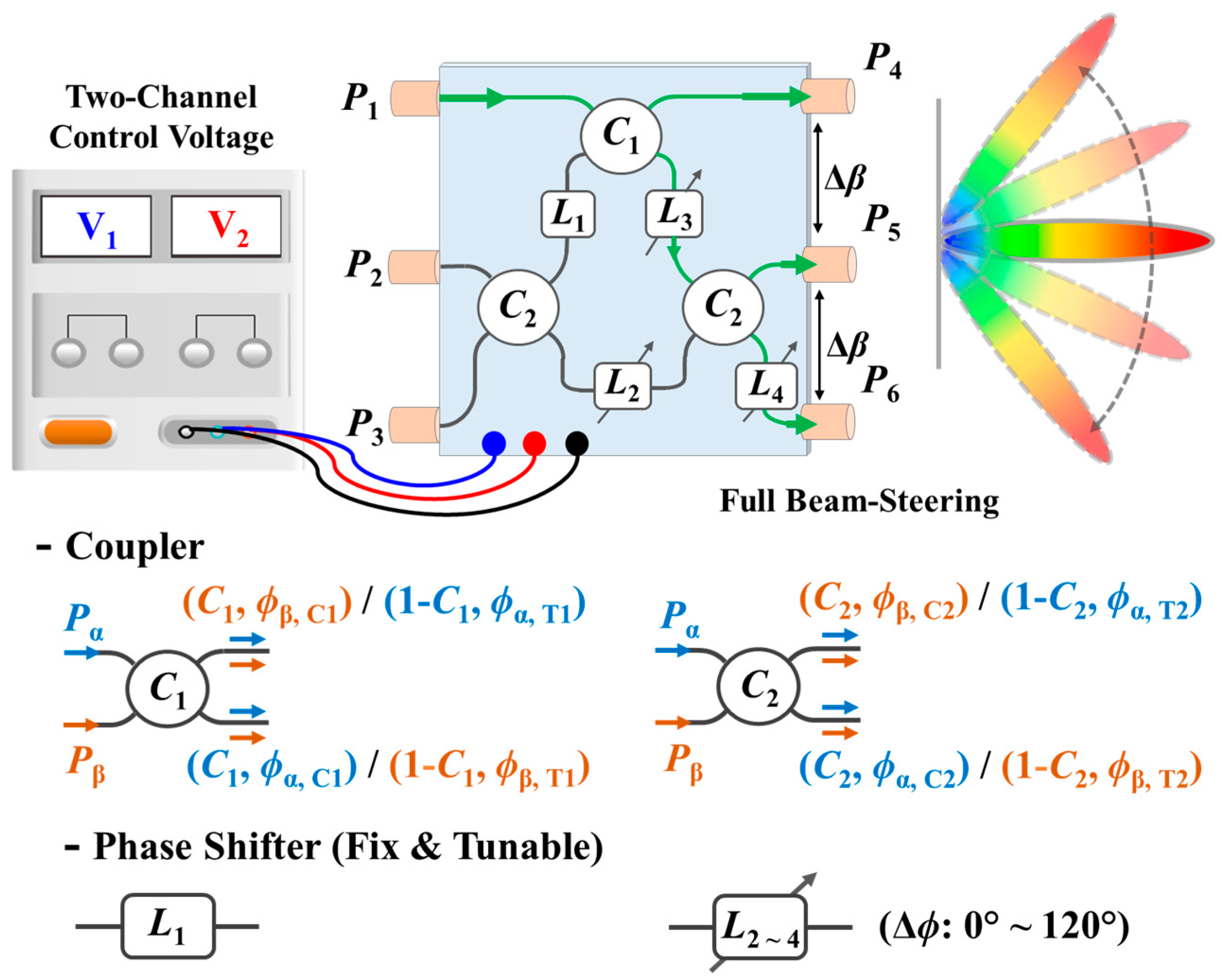
2.2. Design of 2D Tunable Nolen Matrix Beamforming

The fundamental building block tunable 3 × 3 Nolen matrix is a microwave network with three input ports (P1P3) and three output ports (P4P6), as shown in Figure 2. It is composed of three couplers with two different coupling ratios, C1 and C2, three tunable phase shifters (L2, L3, and L4) with a phase tuning range of ϕ2, ϕ3, and ϕ4, and one fixed phase shifter, L1 (phase delay = ϕ1). More specifically, when port Pα of coupler 1 is excited, the signal at the coupling port is C1, and the phase delay is ϕα,C1. While the signal at the through port has a magnitude of (1-C1) and a phase delay of ϕα,T1. Similarly, when Pβ is excited, the same magnitude distributions can be achieved, while the phase delays of ϕβ,C1 and ϕβ,T1 are obtained, respectively. For the other two couplers with a coupling ratio of C2, the corresponding magnitudes and phase delays under different port excitations are shown in Figure 2 as well. More details about coupler design have been addressed in the previous work [21]. In this design, the phase differences of couplers under different port excitations can be expressed as follows:
( ϕ α , C 1 ϕ α , T 1 ) + ( ϕ β , C 1 ϕ β , T 1 ) = π
( ϕ α , C 2 ϕ α , T 2 ) + ( ϕ β , C 2 ϕ β , T 2 ) = π
Also, the corresponding coupling rations C1 and C2 are derived, respectively, to 2/3 and 1/3 by considering the requirement of equal magnitude distribution and progressive phase differences across the entire matrix. Therefore, the S parameters of the 3 × 3 network are decently derived as follows:
S 41 = 3 3 e j ϕ α ,   T 1
S 51 = 3 3 e j ( ϕ α ,   T 2   +   ϕ α ,   C 1     ϕ 3 )
S 61 = 3 3 e j ( ϕ α ,   C 1   +   ϕ α ,   C 2     ϕ 3   ϕ 4 )
S 42 = 3 3 e j ( ϕ α ,   T 1   +   ϕ β ,   C 1     ϕ 1 )
S 52 = 12 12 e j ( ϕ β ,   T 1   +   2   ϕ α ,   T 2     ϕ 1   ϕ 3 )   +   1 2 e j ( ϕ α ,   C 2   +   ϕ β ,   C 2   ϕ 2 )
S 62 = 12 12 e j ( ϕ β ,   T 1   +     ϕ α ,   T 2   +   ϕ α ,   C 2     ϕ 1   ϕ 3       ϕ 4 )   +   1 2 e j ( ϕ β ,   T 2   +   ϕ α ,   C 2   ϕ 2   ϕ 4 )
S 43 = 3 3 e j ( ϕ β ,   C 1   +   ϕ β ,   C 2     ϕ 1 )
S 53 = 12 12 e j ( ϕ β ,   T 1   +     ϕ α ,   T 2   +   ϕ β ,   C 2     ϕ 1   ϕ 3 )   +   1 2 e j ( ϕ β ,   T 2   +   ϕ β ,   C 2   ϕ 2 )
S 63 = 12 12 e j ( ϕ β ,   T 1   +     ϕ β ,   C 2   +   ϕ α ,   C 2     ϕ 1   ϕ 3       ϕ 4 )   +   1 2 e j ( 2 ϕ β ,   T 2   ϕ 2   ϕ 4 )
For the excitation of each input port, conditions such as equal magnitudes, progressive phase distributions, and unique phase differences are required to steer the radiation beam in its dedicated sector. To satisfy the required conditions, the fixed and tunable phase shifters are derived as follows:
ϕ 2 ϕ 4 ϕ 1 = ϕ β , C 2 ϕ β , C 1     90 °
ϕ 3 ϕ 4 = ( ϕ α , C 1 ϕ α , T 1 )     ( ϕ α , C 2 ϕ α , T 2 )   + ϕ α , T 2  
Then, by substituting Equations (17) and (18) into (8)–(16), the progressive phase differences of the proposed tunable 3 × 3 Nolen matrix are obtained as follows:
Δ β 1 =   ( ϕ α , C 2 ϕ α , T 2 )   ϕ 4
Δ β 2 =   ( ϕ α , C 2 ϕ α , T 2 )   ±   120 ° ϕ 4
Δ β 3 =   ( ϕ α , C 2 ϕ α , T 2 )     120 ° ϕ 4
where Δβi denotes the progressive phase differences among the output ports when applying the incident wave from port 1 to port 3 of the 3 × 3 Nolen matrix, respectively. It is observed that Δβi is determined by ϕα,C2ϕα,T2 (phase difference of coupler 2) and phase delay ϕ4. For a given coupler, ϕα,C2ϕα,T2 is a pre-determined constant value. With this fact, it is easy to find that tuning the phase (ϕ4) of the phase shifter L4 will enable continuous progressive phase difference changes in the proposed matrix. From (19) to (21), Δβi features a 120° offset from each other under each input port excitation (i.e., Δβ2 − Δβ1 = Δβ3 − Δβ2 = Δβ1 − Δβ3 = ± 120°), which further reduces the required tuning range of the tunable phase shifter L4 from 360° to 120°, without decreasing the full-coverage range of 360°. In addition, the ϕ2 and ϕ3 tunable phase shifters must follow the change in ϕ4 with the same value or a fixed offset, which would reduce the complexity of the control method in the proposed beamforming phased array.
From the analysis above, the couplers in the proposed 3 × 3 tunable Nolen matrix are designed based on our previous work [21]. After the couplers are determined, the phase differences in each coupler (ϕα,C1ϕα,T1 & ϕα,C2ϕα,T2) can be accordingly obtained, and the phase shifters L1, L2, L3, and L4 can be derived by applying (17)–(18).
To achieve continuous phase tuning with simplified control, a tunable transmission line, as in our previous work [22], has been applied to design tunable phase shifters. It consists of two identical microstrip lines in series and three short-end varactors at two ends and the center. Here, an MA46H120 varactor is adopted as the tunable capacitor, and phase tuning is controlled by two bias voltages. Two proposed phase shifters are cascaded to implement the tunable phase shifters (L2, L3, and L4 in Figure 2), where the phase tuning range is 120° within low loss variation.

2.3. 2D Phased Array for Full-Coverage Beamforming

To realize full-coverage 3D beamforming, six proposed 3 × 3 tunable Nolen matrices are stacked and cascaded to form a 2D antenna feeding network. From Figure 1, three tunable Nolen matrices are installed on the x axis, while the other three are on the y axis. Therefore, there are nine input and nine output ports in this feeding network, and the output ports are connected to a 2D patch antenna array. The array factor (AF) of a planar P × Q antenna array that is excited by incident waves of identical magnitude is derived as follows:
A F P   ×   Q = p = 1 P e j ( p 1 ) ( k d x sin θ cos ϕ     +   β x ) q = 1 Q e j ( q 1 ) ( k d y sin θ sin ϕ     +   β y )
where v is the wavenumber, dx and dy are the distance between the adjacent antenna elements along the x and y axes, βx and βy are progressive phase differences between the adjacent antenna elements on the x and y axes, and θ and ϕ are the radiation beam angles on elevation and azimuth dimensions, respectively. The radiation angle of the main beam in two dimensions can be derived from the following equations:
v d x sin θ cos ϕ + β x = 0
v d y sin θ sin ϕ + β y = 0
By exciting nine different input ports P1P9, the progressive phase differences in the proposed 2D tunable Nolen matrix feeding network on x and y axes (βx and βy) are found, as listed in Table 2. Specifically, there is a 120° phase separation between each set of βx,y by exciting the input port in sequence. βx and βy both have an independent tuning range of 120°. Based on (23) and (24), the main beams point toward nine unique directions in 3D space, and each beam in the cubic sector can be further steered by controlling tunable phase shifters.

3. Experimental Results and Discussion

To verify the theory of the proposed 2D tunable Nolen matrix and 3D beamforming, the simulation was conducted using Keysight ADS (Santa Rosa, CA, USA). A 5.8 GHz tunable 3 × 3 Nolen matrix was designed and fabricated on Rogers RT/Duroid 6002 laminate (Chandler, AZ, USA), which has a thickness of 0.508 mm, a tanδ of 0.0012, and a dielectric constant εr = 2.94, 6

3.1. S Parameter of 3 × 3 Tunable Nolen Matrix
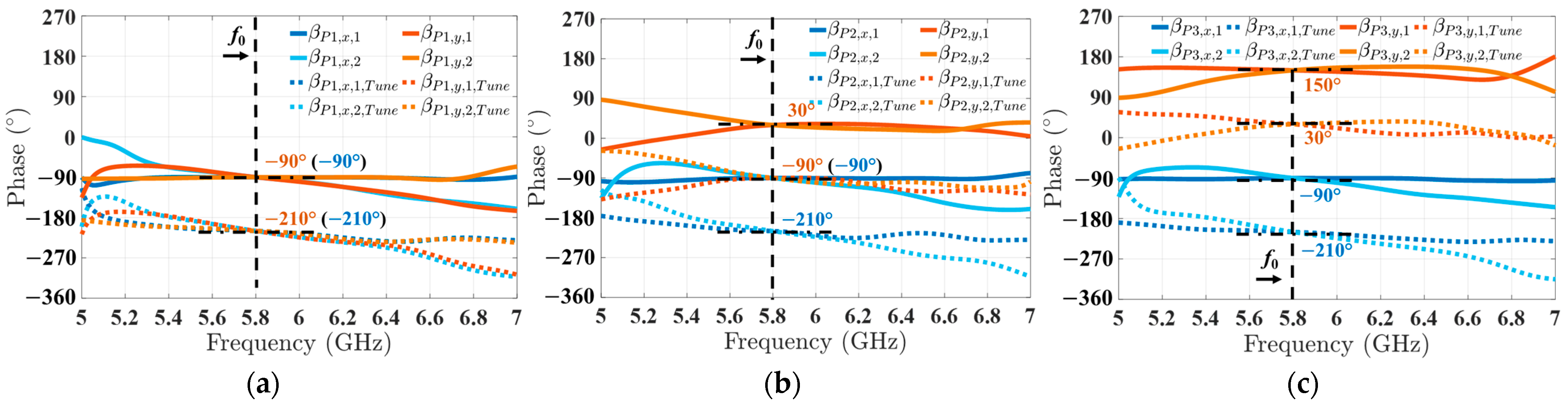
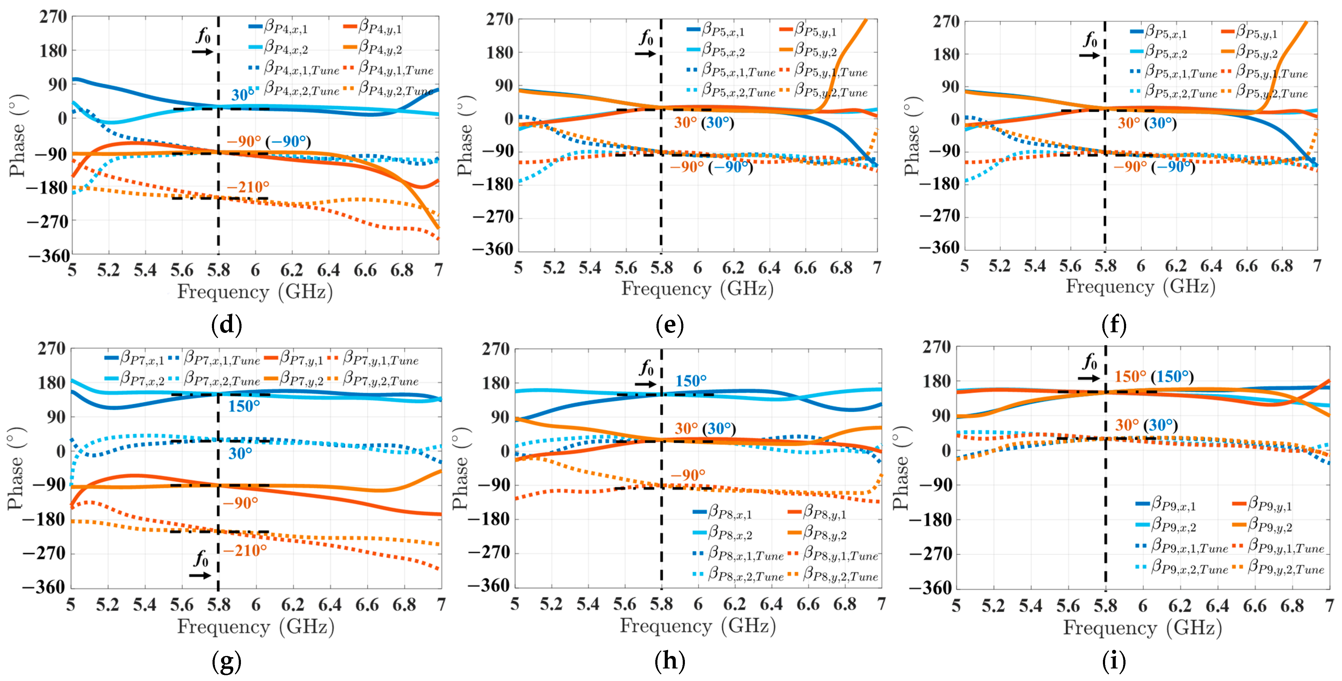
In the simulation results, all output ports experience an ideal insertion loss of 9.54 dB at a center frequency of 5.8 GHz. As shown in Figure 3, the progressive phase differences are plotted in both x and y dimensions (βx and βy) for excitations of nine input ports, where the solid and dash lines denote the limits of phase tuning range (Δβ = 120° contributed from the tunable phase shifters), and blue and red curves indicate progressive phase differences along the x and y axes. In Figure 3a, for excitation on input port P1, the progressive phase differences between the two adjacent outputs are tuned between −90° and −210° in both dimensions. In Figure 3b, for input port P2, βx is tuned from −210° to −90°, while βy is tuned from −90° to 30°. In Figure 3c, for input port P3, βx keeps the same tuning range while βy is tuned from 30° to 150°. It is observed that the excitations on ports along the vertical axis result in an increase of βy (from −210° to 150°), which totally covers the full range of progressive phase differences. On the other hand, for the ports along the horizontal axis (i.e., P1, P4, and P7), βx is tuned from −210° to 150° with no change in βy. Therefore, by exciting the nine input ports (P1 to P9) and tuning the phase shifters, the beam can be radiated in a full 3D space.

3.2. 3D Beamforming

Based on the analysis above, our proposed 2D tunable Nolen matrix enables generating radiation beams in 3D space. In specific, by sequentially exciting the nine input ports, the corresponding radiation sectors can be selected, and the radiation beams in that sector can be continuously steered within the cubic region by tuning the phase shifters. As shown in Figure 4, the radiation beam with normalized gain within each sector is plotted on azimuth (Az) and elevation (El) dimensions. The specified coordinates are simulated based on the Equations (18) and (19). For example, when the input port P5 is excited, the radiation beam is generated within the region of the center sector, and it can be radiated to any angle in that cubic region. Here, in Figure 4, four beams in a clockwise direction, (28°, 45°), (28°, 135°), (28°, 225°), and (28°, 315°), are shown to demonstrate our design concept. Similarly, any radiation beam angle within their dedicated sectors can be generated by tuning phase shifters embedded in the proposed design.

3.3. Evaluation of the Proposed Beamfomring MIMO Channel Capacity

The system channel capacity is evaluated for the proposed 2D Nolen beamforming phased array by applying the Shannon’s formula and equation effective channel matrix H*. The optimum MIMO capacity with the proposed 3D coverage phased array can be expressed as follows:
C = log 2 [ det { γ H * ( H * ) H } ] = log 2 [ det ( γ { B R x H H B T x } { B T x H H H B R x } ) ]
where γ denotes the signal-to-noise ratio (SNR) along the individual diversity branch, and [·]H indicates transpose conjugate. Figure 5 shows the simulation results of the system capacity of the proposed MIMO system versus SNR. Compared with the scheme of 1 × 9 SIMO (or MISO) system and the normal 9 × 9 MIMO system, our proposed 9 × 9 MIMO system provides a higher signal power and offers significantly larger capacity benefits with higher SNR levels.
To verify the design concept, a fundamental tunable 3 × 3 Nolen matrix block operating at 5.8 GHz is designed and fabricated on Rogers RT/Duroid 6002 laminate (Figure 6), which has 0.508 mm thickness, 0.0012 loss tangent, and 2.94 dielectric constant. The overall size of the tunable Nolen matrix is about 113.59 mm × 34.25 mm, which equals 2.19 λ × 0.66 λ (λ: wavelength at 5.8 GHz), as shown in Figure 6. It includes a tunable Nolen matrix, a 1 × 3 Vivaldi antenna array, and a DC control circuit. In future work, more details about the measured results of the proposed 3D beamforming array and system level evaluations are needed. Additionally, further investigations on multi-band/wideband tunable Nolen matrix beamforming phased arrays will be conducted to further optimize their capabilities in high-capacity MIMO IoT communications.
Here, in Table 3, the proposed 2D tunable Nolen matrix phased array has been compared to other MIMO beamforming networks for IoT communications. It can be observed that the proposed design achieves a flexible 3D beam-steering capability and larger MIMO scales to optimize the channel capacity. Also, it features a simplified circuit topology with minimum control units and requiring minimized phase tuning range to achieve a full 360° progressive phase.

4. Conclusions

In this paper, a high channel capacity MIMO wireless communication using a 2D Nolen beamforming array with 3D scanning capability is presented. The 2D beamforming phased array is designed by stacking a fundamental building block consisting of a 3 × 3 tunable Nolen matrix. By exciting nine individual input ports of the phased array, the corresponding radiation beams can be generated and continuously steered on both azimuth and elevation planes to maximize the signal-to-noise ratio (SNR) in the corresponding spatial directions. The simulations have been conducted on both the front-end aspect and the entire system to verify the design theory, and the results demonstrate that our proposed phased array system can increase the capacity margin of next-generation MIMO-enabled IoT communications.

Author Contributions

Conceptualization, H.Z.; methodology, H.Z.; software, H.Z.; validation, H.Z. and H.Y.; formal analysis, H.Z., H.Y., P.L. and S.Z.P.; investigation, H.Z., H.Y., P.L. and S.Z.P.; resources, P.L.; data curation, S.Z.P.; writing—original draft preparation, H.Z.; writing—review and editing, H.Z.; visualization, H.Z.; supervision, B.A.; project administration, B.A.; funding acquisition, B.A. All authors have read and agreed to the published version of the manuscript.

Funding

This research was funded by the National Science Foundation (NSF), grant number ECCS-2124531, and CCF-2124525.

Data Availability Statement

Data are contained within the article.

Conflicts of Interest

The authors declare no conflicts of interest.

References

  1. Grau, A.; Jafarkhani, H.; Flaviis, F.D.A. Reconfigurable Multiple-Input Multiple-Output Communication System. IEEE Trans. Wirel. Comms. 2008, 7, 1719–1733. [Google Scholar] [CrossRef]
  2. Agiwal, M.; Roy, A.; Saxena, N. Next Generation 5G Wireless Networks: A Comprehensive Survey. IEEE Commun. Surv. Tutor. 2016, 18, 1617–1655. [Google Scholar] [CrossRef]
  3. Xu, L.; Chen, J.; Liu, M.; Wang, X. Active Eavesdropping Detection Based on Large-Dimensional Random Matrix Theory for Massive MIMO-Enabled IoT. Electronics 2019, 8, 146. [Google Scholar] [CrossRef]
  4. Cui, S.; Farha, F.; Ning, H.; Zhou, Z.; Shi, F.; Daneshmand, M. A Survey on the Bottleneck Between Applications Exploding and User Requirements in IoT. IEEE Internet Things J. 2022, 9, 261–273. [Google Scholar] [CrossRef]
  5. Rana, A.; Taneja, A.; Saluja, N.; Rani, S.; Singh, A.; Alharithi, F.S.; Aldossary, S.M. Intelligent Network Solution for Improved Efficiency in 6G-Enabled Expanded IoT Network. Electronics 2022, 11, 2569. [Google Scholar] [CrossRef]
  6. Shafi, M.; Molisch, A.F.; Smith, P.J.; Haustein, T.; Zhu, P.; De Silva, P.; Tufvesson, F.; Benjebbour, A.; Wunder, G. 5G: A Tutorial Overview of Standards, Trials, Challenges, Deployment, and Practice. IEEE J. Sel. Areas Commun. 2017, 35, 1201–1221. [Google Scholar] [CrossRef]
  7. Lee, A.; Kim, S.H.; Lee, D.M.; Kim, J.H.; Jang, T.H. The Generalization of Stage-Reduced STPS for Low-Loss Unequal 1 × 4 Phased Array Architecture for 5G IoT Applications. IEEE Internet Things J. 2024, 11, 19978–19987. [Google Scholar] [CrossRef]
  8. Jenn, D.C.; Flokas, V. In-band Scattering from Arrays with Parallel Feed Networks. IEEE Trans. Antennas Propag. 1996, 44, 172–178. [Google Scholar] [CrossRef]
  9. Kang, L.; Li, H.; Wang, X.; Zhou, J.; Huang, J. Circular Polarization-Agile and Continuous Beam-Steerable Array Antenna using A Hybrid Design Approach. IEEE Trans. Antennas Propag. 2022, 70, 1541–1546. [Google Scholar] [CrossRef]
  10. Ren, D.; Choi, J.H.; Itoh, T. Series Feed Networks for Dualpolarized Frequency Scanning Phased Array Antenna Based on Composite Right/Left-Handed Transmission Line. IEEE Trans. Microw. Theory Tech. 2017, 65, 5133–5143. [Google Scholar] [CrossRef]
  11. Abdalla, M.; Phang, L.; Eleftheriades, G. A Planar Electronically Steerable Patch Array Using Tunable PRI/NRI Phase Shifters. IEEE Trans. Microw. Theory Tech. 2009, 57, 531–541. [Google Scholar] [CrossRef]
  12. Fonseca, N.J.G. Printed S-band 4 × 4 Nolen Matrix for Multiple Beam Antenna Applications. IEEE Trans. Antennas Propag. 2009, 57, 1673–1678. [Google Scholar] [CrossRef]
  13. Chen, P.; Hong, W.; Kuai, Z.; Xu, J. A Double Layer Substrate Integrated Waveguide Blass Matrix for Beamforming Applications. IEEE Microw. Wireless Compon. Lett. 2009, 19, 374–376. [Google Scholar] [CrossRef]
  14. Grau, A.; Romeu, J.; Blanch, S.; Jofre, L.; De Flaviis, F. Optimization of Linear Multielement Antennas for Selection Combining by Means of a Butler Matrix in Different MIMO Environments. IEEE Trans. Antennas Propag. 2006, 54, 3251–3264. [Google Scholar] [CrossRef]
  15. Cetinoneri, B.; Atesal, Y.A.; Rebeiz, G.M. An 8 × 8 Butler matrix in 0.13-μm CMOS for 5–6 GHz Multibeam Applications. IEEE Trans. Microw. Theory Tech. 2011, 59, 295–301. [Google Scholar] [CrossRef]
  16. Shao, Q.; Chen, F.C.; Chu, Q.X.; Lancaster, M.J. Novel Filtering 180° Hybrid Coupler and its Application to 2 × 4 Filtering Butler Matrix. IEEE Trans. Microw. Theory Tech. 2018, 66, 3288–3296. [Google Scholar] [CrossRef]
  17. Chang, C.; Lee, R.; Shih, T. Design of a Beam Switching/Steering Butler Matrix for Phased Array System. IEEE Trans. Antennas Propag. 2010, 58, 367–374. [Google Scholar] [CrossRef]
  18. Chu, H.; Hoang, T.; Ji, K.; Ma, T. A Phase Distribution Network Using 2 × 4 Butler Matrix for Linear/Planar Beam-Scanning Arrays. IEEE Access 2021, 9, 133438–133448. [Google Scholar] [CrossRef]
  19. Ren, H.; Zhang, H.; Jin, Y.; Gu, Y.; Arigong, B. A Novel 2-D 3 × 3 Nolen Matrix for 2-D Beamforming Applications. IEEE Trans. Microw. Theory Tech. 2019, 67, 4622–4631. [Google Scholar] [CrossRef]
  20. Zhang, H.; Arigong, B. Full 3D Coverage Beamforming Phased Array with Reduced Phase Shifters and Control 2D Tunable 3 × 3 Nolen Matrix. In Proceedings of the IEEE International Symposium on Phased Array Systems & Technology, Waltham, MA, USA, 11–14 October 2022; pp. 1–6. [Google Scholar]
  21. Zhou, M.; Shao, J.; Arigong, B.; Ren, H.; Zhou, R.; Zhang, H. A Varactor Based 90° Directional Coupler with Tunable Coupling Ratios and Reconfigurable Responses. IEEE Trans. Microw. Theory Tech. 2014, 62, 416–421. [Google Scholar] [CrossRef]
  22. Ren, H.; Zhou, M.; Gu, Y.; Arigong, B. A Tunable Transmission Line with Controllable Phase Shifting and Characteristic Impedance. IEEE Trans. Circuits Syst. II Exp. Briefs 2019, 67, 1720–1724. [Google Scholar] [CrossRef]
Figure 1. MIMO communication with novel 2D Nolen beamforming matrix, where nine individual radiation beams to maximize signal-to-noise ratio (SNR) are generated by exciting corresponding ports (P1 to P9).
Electronics 13 02452 g001
Figure 2. Schematic diagram of single 3 × 3 fully tunable Nolen matrix with two-channel control voltages to realize full beamforming.
Electronics 13 02452 g002
Figure 3. Simulation results of the proposed 2D tunable Nolen matrix with excitation from port 1 to port 9: (a) port 1 excitation; (b) port 2 excitation; (c) port 3 excitation; (d) port 4 excitation; (e) port 5 excitation; (f) port 6 excitation; (g) port 7 excitation; (h) port 8 excitation; and (i) port 9 excitation.
Electronics 13 02452 g003aElectronics 13 02452 g003b
Figure 4. Antenna beams in nine unique radiation sectors by exciting nine input ports, P1 to P9, and continuous steering is achieved from tunable phase shifters.
Electronics 13 02452 g004
Figure 5. Capacity evaluation of 9 × 9 MIMO system with 3D beam-steering Nolen beamforming phased arrays.
Electronics 13 02452 g005
Figure 6. (a) Photograph of the fabricated 3×3 tunable matrix feeding network; (b) photograph of the proposed tunable matrix fully tunable beamforming array.
Electronics 13 02452 g006
Table 1. Examples of progressive phase differences with different phase ratio r.
Phase Differences in 3 × 3 Nolen MatrixExample 1
(r = 0)
Example 2
(r = 0.5)
Δϕ1 = φ1,nφ1,n−1+90°
Δϕ2 = φ2,nφ2,n−1+120°+30
Δϕ3 = φ3,nφ3,n−1−120°−150°
Table 2. Progressive phases and selection of radiation sector under applied input ports.
Port
Excitation
Progressive Phase (βx, βy)Radiation Sector
1(−90°, −90°)Sec. 1
2(−90°, 30°)Sec. 2
3(−90°, 150°)Sec. 3
4(30°, −90°)Sec. 4
5(30°, 30°)Sec. 5
6(30°, 150°)Sec. 6
7(150°, −90°)Sec. 7
8(150°, 30°)Sec. 8
9(150°, 150°)Sec. 9
Table 3. Comparison between a 2D tunable Nolen matrix phased array and other beamforming networks.
[7][9][17][18]This work
Antenna Feed TypeParallelParallelButler matrixButler matrixNolen matrix
Components
Integration
Phase shifter,
power divider, and
amplifier
Divider,
lumped element, and
phase shifter
Coupler,
power divider, and
phase shifter
Coupler,
crossover, and
phase shifter
Coupler and
phase shifter
MIMO Scale4 × 4N.A.4 × 44 × 49 × 9
Scanning Dimension2D2D2D2D3D
Frequency (GHz)282.52.452.45.8
Phase Shifters Number44863
Shifting TypeSwitchingContinuousSwitchingContinuousContinuous
Phase Shifting (°)18090142360120
Progressive Phase (°)360360324360360
DC Control Units47862
Disclaimer/Publisher’s Note: The statements, opinions and data contained in all publications are solely those of the individual author(s) and contributor(s) and not of MDPI and/or the editor(s). MDPI and/or the editor(s) disclaim responsibility for any injury to people or property resulting from any ideas, methods, instructions or products referred to in the content.

