Abstract
Ion-selective field-effect transistors (ISFETs) offer potential as micro-sensors for in situ monitoring of complex target variables in real-time closed loop actions. This article presents the concept and realisation of application-specific ISFET-based measurement systems for two different agricultural domains: infield soil measurements and hydroponic systems. Commercially available ISFETs were integrated as multi-sensor modules as well as single-sensor units for the measurement of plant-available nutrients, such as , , or and pH-values. Moreover, application-relevant pH values as well as temperatures for calibration purposes were measured. ISFETs were selected according to the relevant measurement dynamics for the applications. For the development and testing procedures, a laboratory setup was built up. Supported by reference materials, the outputs of the ISFETs were evaluated with respect to stability under the influence of disturbance variables, reproducibility and settling time. The results were used to develop new readout electronics. Next to stability, conditioning and calibration processes were relevant. The micro-sensors were integrated in new application-specific mechatronic handling systems and process flows. The realisation and tests are presented as well as first measurements in outdoor fields and indoor hydroponic environments.
1. Introduction
Recent technological developments in the field of ion-selective field-effect transistors (ISFETs) have enabled the creation of high-precision primary sensor systems for real-time ion-selective analysis of liquids and gases. ISFTs were first described in the 1970s by Bergveld [1]. The objective was to quantify ion activity in electrochemical and biological environments. Bergveld adapted the MOSFET into an ISFET by eliminating the metal gate and substituting it with an electrolyte solution. Subsequently, Matsuo and Wise [2] proposed an enhanced ISFET design utilising silicon nitride (Si3N4) as the dielectric gate, which they employed as a pH sensor. In 1980, it was demonstrated that an ISFET with a layer of immobilised penicillinase deposited on the dielectric gate could be employed as a penicillin sensor, designated as ENFET [3].
Over the past five decades, numerous articles have been published on the various aspects of ISFET development [4]. The evolution of ISFET measurement technology has been inextricably linked with the continuous development of semiconductor technology. The advent of new production techniques for structures with dimensions in the micrometre and submicrometric range based on monocrystalline silicon, coupled with a deeper understanding of the mechanical and electrical properties of silicon and other materials, has opened up new avenues for this sensor technology [5,6]. Application-specific ISFET sensor systems for measuring nutrients and ingredients also have great potential in agriculture. The temporal limitations of seasonal work activities, the necessity for real-time data under real field conditions, and the lack of analysis laboratory capacity or expensive and time-consuming laboratory analyses pose a challenge and offer the potential for future applications of ISFET measurement technology. A wide range of agricultural and environmental applications for real-time measurement using ISFET technology or ion-selective sensors based on ion-selective electrodes (ISEs) can be found in the literature. For instance, several research groups have explored the potential of mobile nutrient analysis based on ISE or ISFET measurement technology for use in the field. Kim et al. [7] developed a soil preparation method for mobile field laboratories to analyse nitrate (), potassium () and phosphorus (). Additionally, mobile field laboratories for on-site measurements have been developed: for topsoil [8], for pH [9] and for multiple parameters including , and pH [10].
Recently, another agricultural application—ammonium () and potassium analysis in cattle and pig slurry and in digestate—was reported by [11,12]. These measurements were carried out using a measurement system based on ISEs. Son et al. [13] developed a nutrient measuring system for hydroponics using ISEs for ion-specific fertilisation control and set up a study for pepper growing. Furthermore, information on various disturbance variables, such as biofilm formation due to algae growth in the nutrient solution, is provided during the application. Another example of the use of ISEs in environmental analysis for the detection of trace elements, heavy metals and nutrients in water and wastewater is provided by De Marco et al. [14] in a review article. The use of real-time measurement techniques, in this case ISEs, for environmental monitoring is described by De Marco et al. [14] as highly promising and attractive, due to the ability to collect and provide measurement data in a continuous, rapid, relatively low-cost and real-time manner compared to laboratory analysis. It must be acknowledged that any issues that arise with the use of a measurement technology (in this case the ISE measurement unit) when employed in an aqueous solution over an extended period may result from contamination of the electrode, electrode fouling or electrode passivation. It is therefore necessary to implement appropriate solutions such as regular cleaning of the electrodes by rinsing with a suitable solution (for example, a sacrificial calibration standard), conditioning to “activate” the electrode or regular calibration, etc. It is similarly important to optimise the measurement setup regarding any measurement problems that may occur, for example, by carrying out a flow analysis. The objective of these measures is to prevent or reduce electrode drift and instability to maintain measurement reproducibility, measurement dynamics and measurement stability [14].
Benslimane et al. [15,16] employed ISFET measurement technology within a laboratory setting to analyse phosphorus and nitrate concentrations in Moroccan soils. The results of the ISFET measurements exhibited high and very high coefficients of determination, which were compared with the results of classical laboratory analysis for and [15,16]. Chen et al. [17] describe in their publication the measurement of nutrient concentrations in aqueous solution for water quality monitoring and wastewater treatment using the ISFET measurement technique. In comparison to ISFET-based soil nutrient analysis, the advantage of ISFET-based analysis of aqueous solutions is that it requires less sample preparation for measurement with the ISFET. Gieling et al. [18] describe how the supply of specific nutrients (e.g., , ) is adapted in accordance with the actual uptake of nutrients by the plants in the greenhouse. Moreover, the ratio of the individual nutrient concentrations in the nutrient solution can be optimised and adapted to the changing needs of the plant during the growth period [18]. The objective of this approach is to optimise the application of nutrients, reduce the consumption of water, and ensure the maintenance of a consistently high level of product quality through a targeted and precise addition of nutrients [18,19]. ISFET measurement technology offers numerous advantages over ISEs. ISFETs are more sensitive and respond more quickly, allowing near-real-time measurements. As compared to ISEs, they are simpler to use and require less effort for calibrations [17,19,20]. To ensure the successful use of ISFET measurement technology in a completely new application, it is strongly recommended that a bespoke technical system and application design is developed [21].
This article outlines the design and implementation of ISFET-based measurement systems tailored to two specific agricultural applications: soil nutrient analysis in the field and the analysis of nutrients in hydroponic systems. The selected sensors were those available commercially, chosen on the basis of their suitability for the intended future range of measurements.
This article’s structure is designed to provide clarity and is divided into sections as follows. Section 1 is an Introduction to provide context and overview, while Section 2, Materials and Methods, Section 2.1 and Section 2.2, respectively, cover the functional principle of the ISFET sensor, the interfering factors and the structure of the ISFET measurement module. The newly developed control and read-out electronics used during the measurements are described in Section 2.3. Section 3 (System Integration) presents concepts, their implementation, and the first experiments carried out and their results, which are then discussed in Section 4—Discussion. Finally, a summary and an outlook are given in Section 5—Conclusions.
2. Materials and Methods
2.1. Functional Principle of the ISFET Sensor
The fundamental structure of an ion-selective field-effect transistor (ISFET) is based on the classical microelectronic field-effect transistor (FET) structures in silicon. Typically, the flow of current from source to drain (either p- or n-regions) is controlled by the gate voltage. The semiconductor surface is coated with a metal oxide insulator to which the ion-selective membrane is applied (Figure 1).
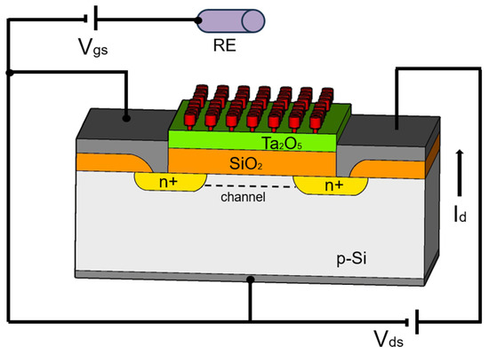
Figure 1.
Schematic diagram of an ISFET as an example: SiO2—gate material, Ta2O5—protection layer, RE—reference electrode, red—ion sensitive membrane as interface to the liquid, modified according to [22].
Silicon oxide (SiO₂), silicon nitride (Si3N4) and, as protection layer, a variety of metal oxides (e.g., Al2O3, Ni2O5, Ta2O5) are typically employed as gate materials. The selection of metal oxide during the fabrication of the ISFETS is contingent upon the intended application, with particular focus on the sensitivity of the sensor, measurement dynamics and the potential measurement range [22,23]. The mechanism of ISFET operation can be derived from the theoretical description of MOSFET operation [4,24,25]. The general equation for the drain current of the MOSFET with a silicon oxide gate, and therefore also of the ISFET, is as follows [26,27]:
where Cgate is the capacitance of the gate capacitor, W and L are the width and length of the gate, µ is the charge carrier mobility of the electrons, is the input voltage between gate and source, and is the threshold voltage.
Assuming a constant mobility µ, the parameter of the geometric sensitivity of the MOSFET, designated as , is a constant. Its value is determined by the design of the MOSFET. The value of is also a constant, determined by the technological manufacturing process of the MOSFET. The voltage is also a constant value, artificially adjusted by the application of a certain voltage between the drain and the source. Only the voltage remains as a variable in this equation, when the MOSFET is subjected to a constant current, . To search for the variable, this equation can be rearranged as follows:
This means that at a constant voltage and a constant current Id, the output voltage is a function of the change in potential at the electrolyte/oxide interface . This implies that when the concentration of ions in the measuring solution is altered, a shift in the − characteristic curve is observed, resulting in the voltage difference being measured. This voltage difference is the variable that describes the ion concentration changing in the measurement solution (Figure 2).
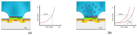
Figure 2.
Schematic diagram of ISFET drain-to-source current vs. gate voltage to illustrate the operating principle of ISFETs, modified according to [28]. (a) Characteristic curve of the ISFET measurement in the absence of desired ions. (b) Shift of the characteristic curve during the ISFET measurement of the liquid with desired ions in constant concentration.
In order to render an ISFET-based sensor sensitive to a specific ion or chemical molecule, an ion-selective membrane is applied to the metal oxide insulator. The solution to be analysed is then contacted with the ion-selective membrane, thereby creating a potential at the membrane surface that controls the current flowing between the drain and source. The strength of the current is a function of the membrane potential, which is a function of the ion activity in the solution to be analysed.
In this context, it is of utmost importance to determine the optimal stable operating point ( and ) for the operation of the ISFET. This parameter, in conjunction with several others, is of particular significance. To achieve this, the operating point of the ISFET should be analysed in conjunction with the current–voltage characteristics of the ISFET. It is also crucial to consider the detection range of the ISFET sensor, which can vary depending on the specific sensor type. The maintenance of and as a constant supply current/voltage of the ISFET sensor offers a better signal-to-noise ratio; a more stable output signal is achieved in comparison to the effects of potential fluctuations in temperature and therefore a better quality of the output signal of the ISFET [29,30]. The operational point of the ISFET is typically provided by the manufacturer and can be modified during the manufacturing process, and subsequently during operation, contingent on the specific requirements of the application [23].
In ISFET sensors, the interface between the solid body (a metal oxide insulator with an ion-selective membrane) and the electrolyte is affected by various factors, resulting in electrical potential differences. Four sources for potential voltage differences are well documented in the literature: Nernst potential [31], Donnan potential [32], electrode potentials [22,23] and double-layer potential, known as the Gouy–Chapman double-layer effect [33]. These four potential differences are fundamental to ISFET operation. In order to achieve an optimised and stabilised ISFET output signal and an enhanced measurement accuracy, it is essential to gain an understanding of the aforementioned factors and to incorporate them into the design and manufacturing process of the ISFET sensor.
In addition to the factors specific to internal design, materials and measurement electrolyte, there are also external influences that can have an impact on the stability and accuracy of an ISFET sensor’s output signal [25]. Some of these external effects are the following:
- Temperature: Changes in the ambient temperature or the temperature of the measurement solution can influence the accuracy and stability of the ISFET sensor measurement because they can affect the properties of the semiconductor materials and the reaction rates in the solution. In extreme cases, excessive temperatures can destroy the sensor.
- Moisture: Moisture can affect the performance of the sensor, especially if the moisture enters the electronics of the sensor, causing corrosion of the contacts or internal shorting.
- Light Sensitivity: Changes in ambient light conditions can affect the stability and accuracy of the ISFET output signal. This is due to the fact that light can affect the electrical properties of the semiconductor material that is used to detect the ions [34].
- Electrical interference: Other ions or chemical compounds in the sample solution can interfere with the ISFET sensor’s output signal, especially if they have similar charges or interactions with the sensor’s gate surface. The ISFET sensor output signal can be distorted by electrical or electromagnetic interference from other sources [35].
- Mechanical stress: Mechanical stress, such as severe vibration or increased pressure, can affect the sensitivity of the sensor and the stability of the output signal, or lead to malfunction or total failure of the electronic circuitry [36].
To ensure the accuracy and reliability of an ISFET sensor’s output signal, it is essential to accurately assess and minimise external influences through effective measures such as temperature compensation, moisture protection and additional shielding against electromagnetic fields.
2.2. Structure of the ISFET Measurement Modules
The sensors used, ISFETs, have been integrated both as multi-sensor modules and as single-sensor units to measure plant-available nutrients such as , , or .
2.2.1. Soil Application
The “soil2data” research project employed a customised ISFET multi-sensor module, NUTRISTAT [37] which was commercially available from MICROSENS SA (Lousanne, Switzerland), for the mobile analysis of soil nutrients in the field. The prototype of the ISFET multi-sensor module used for this research project was developed as part of the EU-funded project NUTRISTAT (FP7-SME-2011). In order to enhance the measurement properties of the ISFET multi-sensor module for the “soil2data” research project, MICROSENS, the manufacturer of the aforementioned device, implemented improvements in terms of measurement sensitivity and measurement dynamics. In terms of construction, the multi-sensor module comprised a closed, opaque LTCC (Low-Temperature Cofired Ceramics) housing that served to enhance its durability and reliability. A measuring chamber with a total volume of approximately 2 mL was integrated into the LTCC housing. Additionally, two small tubes were integrated into the housing of the multi-sensor module: an inlet tube and an outlet tube. This configuration allowed the prepared soil sample suspension to enter and exit in a liquid state, facilitating the feeding of the multi-sensor module and the performance of measurements (Figure 3a).
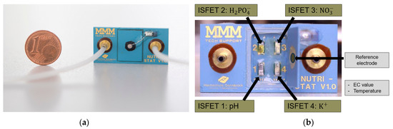
Figure 3.
Multi-sensor module NUTRISTAT for soil application. (a) In a closed housing with inlet and outlet tubes for the measuring liquid; (b) the open housing of the multi-sensor ISFET in individual integrated ISFET sensors [38].
The multi-sensor module comprised four integrated individual Ta₂O₅ isolated gate ISFET sensors for the measurement of nutrients (, , ) and the pH value, with a common solid-state Ag/AgCl reference electrode. Additionally, the module contained two additional sensors: a temperature sensor for the measurement of temperature and an EC sensor for the measurement of the electrical conductivity of the soil suspension (Figure 3b).
The ISFET sensors in the multi-sensor module were selected following an extensive experimental analysis of the measuring range in accordance with the intended agricultural application, namely, soil nutrient analysis directly in the field and the typical nutrient concentration in the soil (Figure 4 and Figure 5). The ISFET multi-sensor module was connected to the control and readout electronics via a socket connector, which served to provide a secure connection. To prevent corrosion when the module was in contact with a liquid solution, the connecting wires within the multi-sensor module, which were those between the drain, source and gate contacts of the respective sensor and the socket connector contacts, were encapsulated within a water-insoluble compound. The common reference electrode was integrated within the cover of the multi-sensor module, thereby ensuring reliable contact with the measuring solution. The design of the specified ISFET multi-sensor module was developed with the specific purpose of facilitating the integration of the multi-sensor module into the broader system for the analysis of soil nutrients in real time in the field.
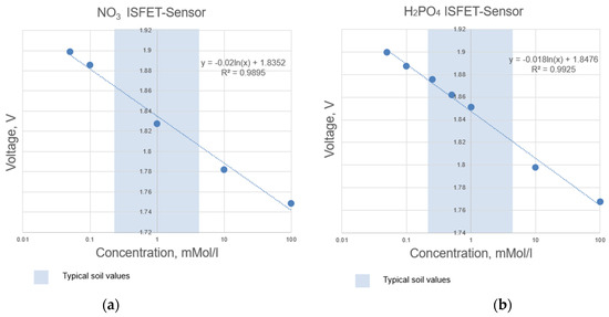
Figure 4.
Determined measuring range according to the calibration curves of selected ISFET sensors integrated in the NUTRISTAT multi-sensor module: (a) ISFET sensor, (b) ISFET sensor.
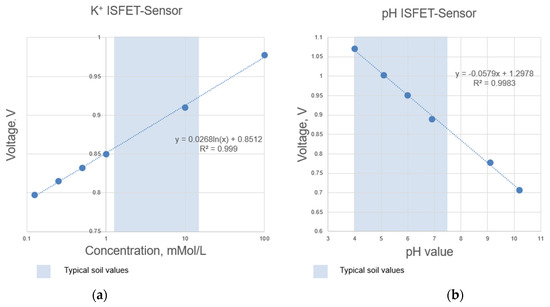
Figure 5.
Determined measuring range according to the calibration curves of selected ISFET sensors integrated in the NUTRISTAT multi-sensor module: (a) ISFET sensor, (b) pH ISFET sensor.
The compact design and small size were selected with the aim of reducing the overall size and bulk of the system. The integration of the multi-sensor module into the overall system for soil nutrients analysis was to be carried out in consideration of upstream work processes before nutrient measurement, including soil sampling, soil sample preparation and filtration of the soil suspension, and downstream work processes after nutrient measurement, including disposal of the soil samples and cleaning of the pipes and the measuring unit. The implementation of the multi-sensor module design enabled the potential interferences outlined in Section 2.1, including sensitivity to light, moisture, corrosion and mechanical stress, to be considered and minimised.
2.2.2. Hydroponic Application
To enhance the adaptability of ISFET measurement technology while considering economic factors, a distinct approach was being employed for real-time-capable nutrient measurement in hydroponic crops as part of the Nutrient+CtrlIVF project. All the ISFET sensors integrated into the ISFET multi-sensor module for soil nutrient measurement were permanently mounted. Consequently, it was not possible to select alternative measured variables or to replace them in the event of one or more ISFET sensors failing. In the event of an ISFET sensor failure, the entire ISFET multi-sensor module, comprising four built-in ISFET sensors, had to be replaced.
In addition to minimising interference during measurement, the possibility of simple and rapid replacement of the ISFET sensors was defined as a further priority for the use of ISFET measurement technology in hydroponic cultures. Single ISFET sensors with similar characteristics to those integrated into the ISFET multi-sensor module designed for soil nutrient analysis were purchased from MICROSENS SA and used in this study. Each ISFET sensor was combined with its own reference electrode and mounted in a threaded sensor housing (Figure 6). For measurement in hydroponic cultures, the sensor housing was screwed into a newly developed measuring chamber, which would be filled with measurement solution
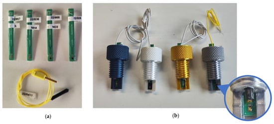
Figure 6.
(a) Single ISFET sensors for measuring , and pH and one reference electrode. (b) The ISFET sensors were integrated into a housing with an individual reference electrode, and the housings were color-coded to reliably identify the correct ISFET sensor during operation.
The measuring chamber was specifically designed to meet the precise specifications of the ISFET measurement procedure. It was opaque, with an inlet and an outlet nozzle for feeding and emptying. The chamber’s construction ensured complete emptying, with no residual contents, thereby eliminating or accounting for potential interferences that might arise when utilising the ISFET measurement module in hydroponic systems. As described above, these potential interferences included sensitivity to light, moisture, corrosion and mechanical loads, among others.
2.3. Control and Readout Electronic
While it is theoretically advantageous to integrate a sensor directly into the requisite electronic circuit, for instance, to enhance the signal-to-noise ratio, this is not the case with an ISFET sensor. Bergfeld [4] posits that the ISFET is a perfect impedance converter at the point of measurement and can therefore be readily connected to a specific signal modulator. As a general design criterion for ISFET amplifiers, it is recommended to avoid the insulation material of the gate oxide in the ISFET in order to prevent unwanted electrical conductivity. ISFETs are polar components, similar to electrolytic capacitors. Therefore, it is necessary to ensure that the silicon gate is always positively biased towards the electrolyte. The simplest way to fulfil this requirement is to use n-channel components in the “normal state”. In the event that the measurement solution can only be grounded randomly in practice, it is advisable to ground it anyway, using a grounded reference electrode [33]. The signal amplifier must then consist of a system in which the source line is positively biased and has protection against high voltages, while the drain line is at a slightly higher potential. This helps to ensure the stability and accuracy of the output signal of the ISFET sensor.
A few other amplifier systems have been published in the literature, e.g., [25,39], and are commercial available [40]. It should be noted that many amplifier systems do not meet the precision requirements in terms of accuracy, signal dynamics and reliability of ISFET measurements. These factors have repeatedly proven to be interference factors in the series of measurements. Furthermore, the reference electrode must be positioned accurately and with precision to avoid introducing further errors into the measurement process. In situations where multiple ISFETs are used simultaneously in a very confined space, using a single reference electrode, and applying a feedback system to the reference electrode, can add to the challenges. This can significantly affect the ability to make accurate and reliable measurements, as the potential noise and interference will affect all ISFETs sharing the same reference electrode [4].
The use of the ISFET multi-sensor module for soil nutrient analysis with four individual ISFETs required the implementation of a special electronic circuit to control the ISFETs and to read the output signal from each individual ISFET sensor. The development of a new circuit permitted the consideration of the requirements and distinctive features of the ISFET multi-sensor system and the realisation of application-specific solutions for the precise and dependable acquisition of data. Such a circuit offered the possibility of minimising disturbances and interferences, improving the quality of the output signal and ensuring efficient communication with each individual ISFET in the multi-sensor module. Furthermore, an application-specific circuit often enables better integration and adaptation to specific requirements of application and individual experimental conditions.
The development of the control and readout electronics for the ISFET multi-sensor module was based on the use of classic analogue signal amplifiers, which have already been described in several literature sources, e.g., [39,40]. The use of already proven circuit concepts and implementation methods allowed for the acceleration of electronics development by drawing on existing know-how and experience. Furthermore, the utilisation of validated methodologies provided a certain degree of assurance with regard to the performance and reliability of the electronics, as these had already been employed successfully in other applications (Figure 7).
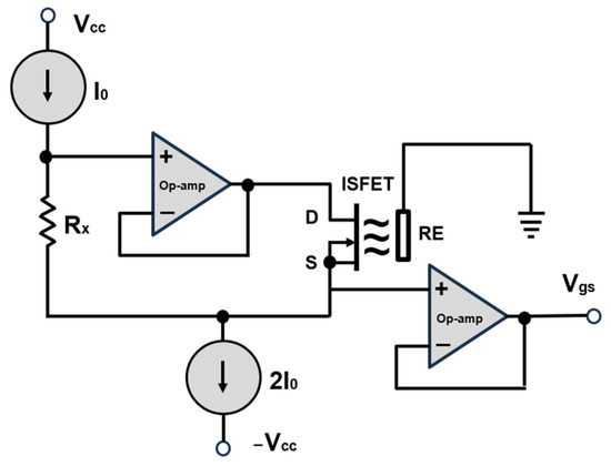
Figure 7.
A classic, commercially available configuration for the biasing of ISFET sensor. D—drain, S—source, RE—reference electrode. Modified according to [40].
In order to ensure optimal performance and compatibility with the ISFET multi-sensor module, to minimise the already known interference factors and to meet the requirements for the use of the module, further adjustments were continuously made to the electronic circuit for control and readout of the ISFET. These included the implementation of four galvanically isolated circuits, the selection of an operational amplifier for each circuit capable of processing both—positive and negative—ISFET output signals, and the introduction of noise suppression measures, including the switching off of inactive measurement channels and the earthing of the reference electrode and thus the measurement solution (Figure 8).
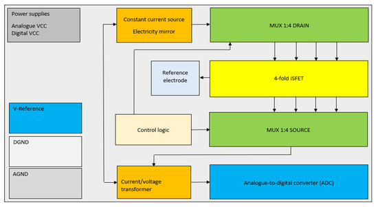
Figure 8.
The block circuit diagram represents the schematic of the implementation of the biasing ISFET multi-sensor.
In order to minimise the influence of electromagnetic fields, short connection paths were introduced. The output signal was amplified and an analogue-to-digital converter was used for the digitisation of an analogue signal. Interface adaptations were made, including connection to a bus interface for further signal processing (Figure 9). All of the aforementioned adjustments were subjected to extensive laboratory testing and validation to guarantee that the control and readout electronics of the ISFET multi-sensor module were fully compliant with the specified application-specific requirements [41].
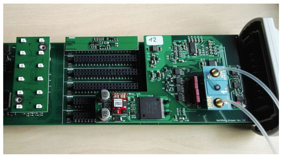
Figure 9.
Realisation of the control and readout electronics (see Figure 8) for an ISFET multi-sensor module including inlet and outlet pipes for the injection of the measuring liquid.
3. System Integration
3.1. Concept
3.1.1. Soil Application
To implement ISFET measurement technology for real-time nutrient analysis in a process sequence, it is necessary to break down the main process into sub-process steps. These individual sub-process steps must then be analysed regarding the integration of ISFET measurement technology. It is not sufficient to consider only the actual sub-process step of measurement; upstream sub-process steps must also be included in the analysis and consideration.
In the “soil2data” research project, a corresponding concept for mobile nutrient analysis in the field has been developed and implemented. Hinck et al. [42,43] describe the changes in the “traditional soil sampling with analysis in the laboratory” process and the new soil2data process with soil sample collection and subsequent analysis in the field. Furthermore, Riedel et al. [38] describe the integration of ISFET technology into the analysis process, with the necessary preparation of the sample material to produce an aqueous extraction for the analysis of plant-available nutrients in the field in a mobile field laboratory. In a similar vein, Nadjenko et al. [44] argue for the necessity of an expedient soil preparation method for nutrient analysis in the field, with the aim of achieving a high correlation with the generally accepted standard preparation method. This would facilitate the application of associated fertiliser recommendations. A corresponding procedure for a field-suitable express method for soil sample preparation in real-time soil nutrient analysis for the mobile field laboratory “soil2data” is presented by Nadjenko et al. [44].
When integrating ISFET measurement technology with conventional methods of soil nutrient analysis, it is important to note that two different soil preparation and analysis methods are used as standard in the laboratory. These include the actual nutrient analysis and the pH analysis (see Table 1). The extraction agent, e.g., CAL with a pH of 4.5, changes the pH of the soil suspension being analysed. This must therefore be taken into account when measuring the pH in the procedure. The preparation times (Table 1) are also too long for field analysis. It is therefore important to ensure that the different requirements and procedures for analysing different soil parameters are taken into account.

Table 1.
Analysis method, extraction agent, ratio soil/extraction agent and preparation time for selected nutrients and pH value [45].
When developing the concept for on-the-go soil analysis with the ISFET multi-sensor module, all the above-mentioned features were considered. A two-stage standard-oriented preparation procedure was developed, utilising the same extraction agents as those employed in classical laboratory analysis. This express extraction method, designated “soil2data”, enables the preparation of the soil sample and extraction of nutrients within 10 min [44].
Subsequent to the extraction process, the soil suspension was filtered to obtain a clean suspension devoid of coarse soil particles, thereby facilitating nutrient analysis with an ISFET multi-sensor module. The liquid was then fed directly into the ISFET multi-sensor module, where the desired soil parameters, including nutrients, pH value, liquid temperature and electrical conductivity, were measured. Finally, the ISFET multi-sensor module was cleaned to remove the suspension that remained within it.
In developing the concept for on-the-go soil analysis with the ISFET multi-sensor module, all the aforementioned features were considered. A two-stage standard-oriented preparation procedure was developed, in which the same extraction agents were used as in classic laboratory analysis. The express extraction method “soil2data” makes it possible to prepare the soil sample taken and extract the nutrients within approximately 10 min [44]. Following the extraction process, the soil suspension is filtered to obtain a clean suspension devoid of coarse soil particles, which is then fed directly into the ISFET multi-sensor module for nutrient analysis. The desired soil parameters, including nutrients, pH value, liquid temperature and electrical conductivity, are then measured. The first analysis stage involves analysing the pH value and -, while the second analysis stage detects - and . Furthermore, the ISFET multi-sensor module can be cleaned in order to remove any residual suspension that may remain within it. This can be done by analysing - and in the first analysis stage. Finally, the ISFET multi-sensor module is cleaned.
The activities required as part of a sub-process were designed with a modular structure of the overall system in mind. This was done with the intention of avoiding incompatibilities and of enabling the realisation of automated process sequences. The necessary interfaces between the individual sub-processes and the components used were defined in order to achieve this. An ISFET-based soil nutrient measuring system was designed and constructed. This system accepts a prepared and filtered soil suspension as an input variable and provides the nutrient contents of nitrate , potassium and dihydrogen phosphate , the EC value and the pH value as output variables.
3.1.2. Hydroponic Application
The integration of ISFET measurement technology into hydroponic cultures is associated with fewer obstacles compared to on-the-go analysis of soil nutrients. All hydroponic systems provide plant-available nutrients via a prepared liquid, known as a nutrient solution [46,47,48]. The nutrients are also added in liquid form. This implies that, in contrast to soil nutrient analysis, the complex and time-consuming preparation process is no longer necessary at this point, and the prepared liquid from the running hydroponic system can be used directly for analysis with the ISFET measurement module. The presence of small dirt particles in this treated liquid, which can influence the measurement with ISFET sensors, necessitates pre-filtration, thereby improving the quality and stability of the measurement signal.
The current most widely used method for measuring and dosing nutrients in hydroponic systems is the determination of the electrical conductivity (EC value) of the nutrient solution in the system. This approach was first described by Jones [47] and was subsequently refined by Jakobsen et al. [49]. However, this value does not provide any information about the contents of the individual nutrients or their ratio to each other, which are of great importance for the successful growth of the culture in hydroponic systems. Over time, individual nutrients may become enriched or deficient, which can have a negative effect on plant development, yield and health. In certain cases, an overview of the current concentrations of certain ions in the nutrient solution can be obtained with the help of rapid tests. However, these tests are not available for all relevant ions, are sometimes complicated to use and are relatively inaccurate. A complete nutrient analysis is only possible in a laboratory setting, which is rarely carried out due to the costs and technical complexity involved. As a result, there is presently a dearth of prompt responses to unfavourable alterations in nutrient concentrations. Therefore, regular (partial) nutrient solution changes in the entire hydroponic system are currently required. The application of ISFET measurement technology offers a potential solution to this problem. It enables the measurement of the contents of individual nutrients in a nutrient solution in quasi-real time and, in conjunction with a corresponding dosing unit for the addition of the analysed nutrients, allows the concentration to be adjusted to the desired level.
Nitrate , potassium , ammonium and pH have been selected as the measured variables that are relevant for demand-based control in hydroponics. The design of the ISFET measurement system—an ISFET measurement module with an application-specific measurement chamber—offers the possibility and flexibility to use other ISFET sensors to measure other ions, e.g., The measurement setup can also be extended to integrate other ISFET measurement systems to extend the range of measured variables. As hydroponic cultures are usually operated in climatic chambers with constant humidity and air temperature, as well as constant nutrient solution temperatures, it is not necessary to integrate a temperature sensor in the ISFET modules.
3.2. Realisation
3.2.1. Soil Application
The specifications established during the concept phase for the two ISFET-based measuring systems—soil application and hydroponic application—were duly considered and fully implemented during the realisation phase. When an ISFET measuring system is utilised in a mobile field laboratory in the field, the system is exposed to a multitude of environmental factors, including dust, rain, light, and so forth. In order to protect the ISFET multi-sensor module with the associated control and readout electronics from the environmental influences of splash water, dust, vibrations and light, the aforementioned module was mounted within a dust and splash-water-protected opaque switch cabinet on the mobile carrier platform “Mobile field laboratory soil2data” (Figure 10).
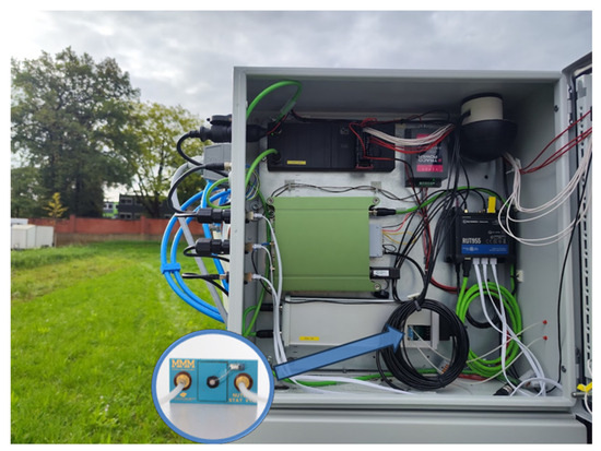
Figure 10.
System integration of ISFET measurement system in soil application.
In order to reduce vibrations during operation, both the switch cabinet on the carrier platform and the ISFET measuring system within the switch cabinet were fitted with rubber feet at the relevant attachment points. The requisite hardware interfaces for the provision of a measuring solution to the ISFET multi-sensor module were integrated. This was necessary in order to enable the soil suspension to be filled from the soil sample preparation module into the ISFET multi-sensor module during the process.
Secondly, it was necessary to enable the calibration or conditioning of the integrated ISFET multi-sensor module in the overall system. Furthermore, interfaces were integrated to empty, clean and fill the ISFET multi-sensor module with conditioning solution. The ISFET multi-sensor module was accessible in the event of a fault due to the arrangement of the individual components, and this also enabled the ISFET measuring system to be replaced quickly. It is important to note that in the event of an ISFET sensor failure, the entire multi-sensor module should be submerged. The influence of temperature changes was recorded by the temperature sensor integrated in the ISFET multi-sensor module and calculated by software, and taken into account accordingly when evaluating the analogue signals of the individual ISFET sensors. Furthermore, a pipeline for data processing and an interface for transferring the measurement data was implemented in the software. The measurement data could be sent directly from the field via mobile data connections to various web-based applications or AI-based evaluation systems for further evaluation or utilisation. It was also possible to retrieve and use the information required for sampling, such as soil sampling plans, from web-based applications [50].
3.2.2. Hydroponic Application
The integration of ISFET measurement technology into hydroponic systems is less challenging than the integration of ISFET measurement technology for soil application with respect to sample preparation. All hydroponic systems supply nutrients available to the plant via a prepared liquid known as the nutrient solution [46,47,48]. Nutrients are also added in liquid form. This implies that, in contrast to soil nutrient analysis, the complex and time-consuming preparation process is not required at this stage. Instead, the nutrient solution can be utilised directly from the operational hydroponic setup for analysis via an ISFET measurement module. The presence of small dirt particles in the nutrient solution, which can affect the measurement with ISFET sensors, makes pre-filtration necessary and improves the quality and stability of the measurement signal.
For ISFET-based nutrient measurement in hydroponic systems, the ISFET measurement system was designed to be compact and mobile. This had the advantage that the ISFET measurement system, consisting of the ISFET measurement modules with the connected control and readout electronics and the relevant equipment for feeding and cleaning the measurement chambers, could be flexibly integrated into an existing hydroponic system and flexible adjustments could be made at any time. The ISFET measurement system and integrated components were housed in a splash-proof and light-proof enclosure (Figure 11).
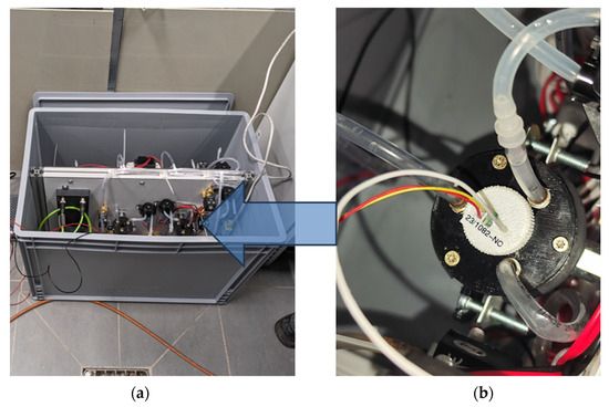
Figure 11.
System integration of ISFET measurement system with additional components in hydroponic application. (a) ISFET measurement system including four measurement chambers, (b) an example measurement chamber with integrated -ISFET sensor (see Figure 6b).
The measurement chambers containing the ISFET modules were opaque and fitted with a cover. The measurement chamber with cover provided a closed measurement chamber and protected the measurement chamber from dirt and dust. The cover and the bottom of the measuring chamber were fitted with hose connections for filling, emptying and cleaning. The test solution was taken directly from the nutrient solution, filtered and filled into the test chambers. A basic calibration or conditioning of the individual ISFET sensor modules could be carried out via the hose connections.
The integrated pumps and valves could be individually controlled via specified software. The software was a prerequisite for the automation of the processes. The software evaluated the calibration data and measurement data using stored evaluation algorithms and converted the measured variable millivolts into a standard concentration specification such as moles per litre or milligrams per litre, before outputting the results. The measured data was transferred to a system unit of the hydroponic system via a defined interface and was available as a control variable for nutrient dosing, among other things.
3.3. First Experiments and Results
Based on several application-oriented experiments in the two agricultural use cases—mobile analysis of soil nutrients and analysis of nutrients in hydroponic cultures—the following questions were investigated:
- Validation of the developed control and readout electronics.
- Validation of the ISFET sensor modules in combination with the control and readout electronics.
- Validation of the implemented preventive measures against known interfering factors.
- Validation of the overall ISFET-based measurement system under real measurement conditions.
The following evaluation criteria [51] were used to verify the general functionality of the control and readout electronics and their functionality in combination with the ISFET sensor module in both—soil and hydroponic—applications:
- Stability: Stability was described by the sensitivity of the ISFET chip and the drift during the measurement. Stability was defined as a horizontal measurement curve with an acceptable level of noise in the measured value.
- Reproducibility: Reproducibility meant that a sensor gave the same measurement result after repeated measurements with the same measurement solution concentration.
- Response behaviour: The response behaviour described the course of the measurement curve when the measurement solution concentration changed.
- Selectivity: In this context, selectivity described the ion selectivity or ion sensitivity of the ISFEF sensor to the defined ion.
In addition, the combination of control and readout electronics and the ISFET sensor module was investigated with regard to the determination of the lower detection limit. The lower detection limit was the lowest concentration in a calibration series above which the ISFET sensor could no longer measure or produce a stable output signal (Figure 4 and Figure 5). The first tests were carried out under laboratory conditions whereby the ISFET sensor was manually filled with the solution to be measured. For this purpose, different calibration series of the nutrients to be tested (, , , pH) and their combinations (e.g., KNO3, KCl, KH2PO4, NaCl) were prepared and applied in different concentrations. The operating point of the ISFET was recommended by the manufacturer and adopted for the measurements, with a voltage of 0.5 V and a current of 100 µA. The data sampling frequency was set to 1 Hz. The analogue output voltage of each ISFET sensor was measured. The increase in voltage as a function of the change in concentration of the respective ion is between 30 and 60 mV per decade. Newly developed control and read-out electronics keep electronic noise in the 3 mV range.
It is well documented in the literature that ISFET sensors exhibit a high degree of cross-sensitivity to interfering elemental ions, e.g., [52], including H+, K+, Na+ and Cl [53]. This cross-sensitivity can significantly distort the outcomes of ISFET sensor measurements. The objective of this experiment was to determine the response characteristics of the ISFET sensor by utilising a combination of different nutrients in the measurement solution. In parallel, the response time and selectivity of the ISFET sensor were evaluated in combination with control and readout electronics. Figure 12 illustrates an example of a measurement conducted using an H2PO4-ISFET sensor. The multi-sensor module was initially filled with a KNO3 solution with a concentration of 10 mMol L−1. Subsequently, an solution with a similar concentration of 10 mMol L−1 was added. It can be observed that the -ISFET sensor responded immediately to the measurement solution. The amplitude of the output signal became more stable, indicating a fast response time. The signal stabilised completely after a measurement time of approx. 200 s. In order to compensate for the effect of the cross-sensitivity of the ISFET sensors to interfering elemental ions in soil application, the calibration liquids were prepared on the basis of the same extraction agent that was used in the application (Table 1).
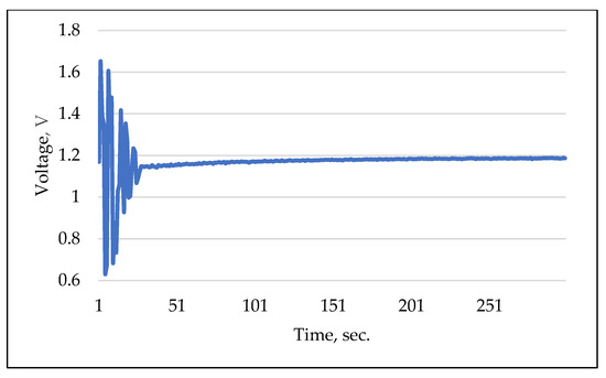
Figure 12.
Example of selectivity and response measurement using -ISFET sensor.
In hydroponic applications, the composition of dosing nutrient solutions is unrestricted, allowing the combination of multiple elements, such as KNO3, NH4, and KH2PO4, among others. The combination of several dosing nutrient solutions that do not contain interfering ions or whose concentrations are significantly lower (by a factor of 10) than the concentration of the ion to be measured helps to account for or avoid the ISFET sensor cross-sensitivity effect to interfering elemental ions.
The impact of varying light conditions during an ISFET sensor measurement on the output signal was investigated. In order to achieve this, measurements were conducted using a commercially available ISFET-based pH meter (Company Hach, H-Series ISFET pH-Electrode). The pH measurements were conducted under varying illumination intensities, specified in lux, with two pH buffer solutions. The pH values were 4.01 and 7.00 (Figure 13).
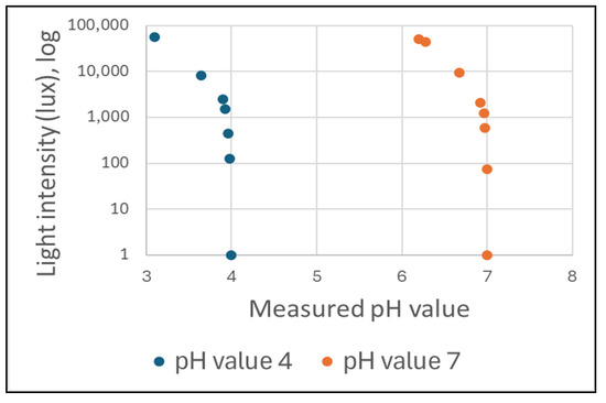
Figure 13.
The influence of light on the pH value measurement result during a measurement with an ISFET-based pH meter.
The pH values and the light intensity in lux were recorded and subsequently analysed. As the light intensity increased, the pH value measured decreased in comparison to the pH value of the buffer solution. The effect of light sensitivity was clearly discernible in the curve at a light intensity of 1000 lux. It has been demonstrated that the sensitivity of an ISFET sensor with a Ta2O5 membrane to optical radiation exerts a considerable influence on the sensor’s analytical behaviour. In order to gain insight into this phenomenon, studies were conducted which examined the kinetic processes involved in the relaxation of a long-term dynamic electric current under the influence of light [34,54,55]. These investigations revealed a relationship between the sensitivity of an ISFET sensor to light and charge generation in the Ta2O5 layer.
In the course of investigating the temperature sensitivity of the used ISFET sensors, a number of measurement series were carried out at various temperatures of the measurement solution. The results demonstrated that the temperature influence was direct (Figure 14), and that the output signal of the ISFET sensor exhibited a proportional dependence on temperature. The figure illustrates an example of the measured values recorded during the measurement of the -ISFET sensor, which was integrated into an ISFET multi-sensor module, as well as the temperatures of the measurement solution, which were also recorded. The aqueous solution of KCl with a concentration of 10 mMol L−1 was used as the measuring solution. The left axis represents the output signal of the ISFET sensor, which is expressed in voltage (V). The right axis depicts the temperature, expressed in degrees Celsius (°C). It can be observed that the measured value increases as the temperature of the test sample rises and decreases as the temperature falls, while the concentration of the test sample remains constant.
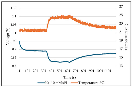
Figure 14.
Temperature sensitivity of the ISFET sensor using example of -ISFET.
Calibration of the ISFET sensor plays a significant role in the overall process of ISFET-based nutrient analysis. The ISFET sensor provides an analogue output signal (voltage) that is dependent on the concentration of ions in the measured liquid. This output voltage can only be related to the respective nutrient concentration by recording the calibration curve of the ISFET sensor module. This is done by filling the ISFET sensor with a solution of known nutrient concentration and recording the output voltage of the ISFET sensor module.
A calibration series of an ISFET sensor contains several measurement solutions with different concentrations, e.g., 0.1 0.5 , 1 , 5 and 10 and for the pH ISFET sensor, pH 4, pH 6, pH 7 and pH 10 liquids (Figure 15). The result of the calibration is a calibration curve voltage vs. concentration, which makes it possible to relate the output voltage of the ISFET module to the concentration of the nutrient in question (Figure 16).
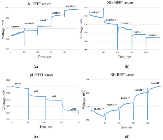
Figure 15.
Measurement data during the calibration series of an ISFET sensor, measurement time 300 s per concentration, sample rate 1 Hz. (a) ISFET sensor, (b) sensor, (c) pH ISFET sensor, (d) ISFET sensor.
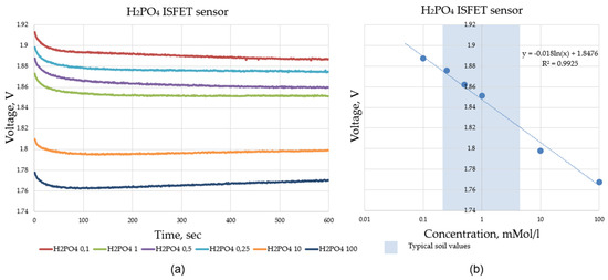
Figure 16.
Validation data of the ISFET multi-sensor system, measurement time 600 s per concentration, sample rate 1 Hz; (a) shows the recorded raw sensor data of the ISFET sensor when measuring the calibration liquids with different ion concentrations and (b) shows the evaluated sensor data used to construct the calibration curve.
Following the completion of the validation process, it was determined that the control and readout electronic components required redesign. These were revised in two distinct iterations with regard to the interwoven circuit components and the control behaviour of the electronics. This was necessary because the selected evaluation criteria were not met by the output signal of the ISFET sensor.
LabView-based software was developed to record, store and analyse the output signals from the ISFET sensor module. This software allowed flexible adjustment of response parameters such as sampling time and frequency of the ISFET sensor to find the optimum parameters for the control and readout electronics to fully meet the evaluation criteria. In addition, the graphical tools implemented in the test software made it possible to monitor the signal waveforms in real time, which was very useful for the analysis of the experiment.
During the validation measurements conducted with the soil application, an additional interference criterion was identified using the ISFET multi-sensor module. Unexpectedly, a sudden increase in the amplitude of the output signal was detected when switching between channels during the measurement. Further analysis with the oscilloscope confirmed that this was due to residual electrical capacitance on the semiconductor surface of the ISFET sensor—when the multiplexer switches the drive channel from one ISFET sensor to another (e.g., from channel 1 to channel 2), a sudden increase in the amplitude of the output signal was detected. When switching the control channel from one ISFET sensor to another (e.g., from channel 1 to channel 2) in an ISFET multi-sensor module and interrogating the output signal (channel 2), a potential remains on the semiconductor surface of the previous ISFET sensor (channel 1) which acts on the output signal of the currently active ISFET sensor (channel 2) via a common reference electrode and a common measuring liquid (Figure 17).
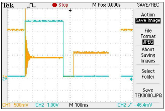
Figure 17.
Screenshot of an oscilloscope measurement showing the capacitive residual charge of an ISFET in an ISFET multi-sensor module—the orange curve is the output signal, the blue curve is the switching signal of the multiplexer.
The elimination of the phenomenon was achieved by means of two measures:
- All inactive ISFET sensors were grounded.
- A time delay of 180 ms was implemented in the software for the sampling of the output signal of the active ISFET sensor to allow the residual capacitance of the previous ISFET sensor to dissipate (so-called time delay).
After implementing these measures, this residual capacitance effect could no longer be detected in the ISFET multi-sensor module.
Further experiments were carried out in the area of handling the ISFET sensor and the ISFET multi-sensor module. As part of this study, new application-specific methods were developed in the areas of conditioning, storage (dry and wet) and application-specific calibration procedures for the ISFET sensors used. This concerned both the composition of the liquids used for the processes and the process times. The lower detection limit for each ISFET sensor in combination with the control and readout electronics was experimentally determined (Table 2).
Table 2.
The experimentally established lower detection limit for each individual ISFET sensor.
After validation of the control and read-out electronics [38], the concepts for ISFET-based nutrient analysis described and developed in Section 3.2 were implemented and experimentally validated. The overall system “soil2data mobile field laboratory” for mobile soil nutrient analysis was evaluated under real field conditions. The preparation procedure was carried out with two preparation steps using collected soil samples. The resulting soil suspension was analysed with the ISFET measuring system for the nutrient contents of , and and pH value. At the same time, reference samples were taken for conventional laboratory analysis. These were sent to the laboratory for nutrient analysis in order to compare the results. This comparison provided an indication of the quality of the data that could be obtained using the ISFET measurement system.
Using the ISFET-based nutrient measurement system, the first validation under field conditions for soil application was carried out on 15 different sample types using the new express extraction method “soil2data”. The exemplary results from the determination of soil pH, shown in Figure 18, showed a high R2.
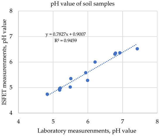
Figure 18.
Correlation of soil pH values measured with ISFET multi-sensor and laboratory results.
During the validation of the ISFET-based nutrient measurement system in hydroponic cultures, the measurement system was integrated into the ongoing process. A bypass was created for the recirculated nutrient solution to the recirculation tank. The ISFET measurement chambers were filled via the bypass. Immediately after filling, a sample was taken manually for reference analysis. The nutrient measurements with the ISFET-based system were fully automated. The nutrient contents of , and and the pH in the nutrient solution were analysed.
The reproducibility of the output signal was also analysed. The results of the calibration curves for ISFET sensors for these tests are shown as an example in Figure 19 and Table 3.
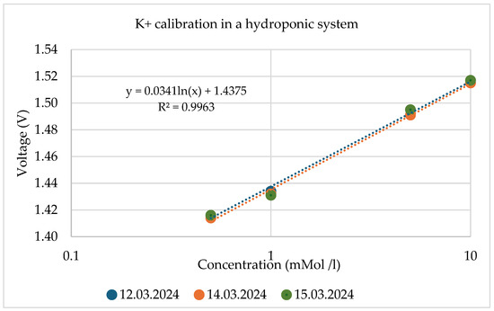
Figure 19.
Reproducibility validation using the recorded calibration data of the ISFET during measurements in hydroponic systems.
Table 3.
The recorded calibration data of the ISFET during measurements in hydroponic systems.
4. Discussion
When using ISFET technology, the influence of ambient light on the output signal of the meter must be considered and prevented by appropriate countermeasures. The influence of light on ISFET measurement was verified using a commercially available ISFET-based pH meter. Our own measurement results confirmed the information given by Ito [34] that a significant drift in the output signal of the ISFET sensor can be seen from a light intensity of more than 1000 lux (see Figure 8). The illuminance of 500 to 1000 lux corresponds to the usual lighting in offices and laboratories. It is therefore recommended that an ISFET-based measurement be carried out in a shaded area or in an area darkened against ambient light. These aspects were taken into account in the design of the ISFET-based soil nutrient measurement with the soil2data mobile field laboratory and the ISFET-based nutrient measurement in hydroponic systems. The ISFET multi-sensor module, which was installed in an opaque housing, was also installed in an opaque control box in the soil2data mobile field laboratory. The opaque measurement chamber of the hydroponic system ensured that the ISFET sensor was protected from the effects of light.
The temperature sensitivity of the ISFET measurement technique is well described in the literature, e.g., [56,57] and was confirmed by our own experimental measurements. To calculate the parameters for temperature compensation, the temperature of the ISFET multi-sensors was measured by temperature sensors in the mobile field laboratory “soil2data” for the soil application. In the hydroponic system, the temperature of the nutrient solution was assumed to be constant due to the environmental conditions.
The calibration series proved the functionality of the control and readout electronics in combination with the ISFET measurement technology. The calibration series was successfully completed. The curves for the different concentrations were stable. This was shown, as an example, for . The ISFET sensor employed for the measurement of , for example, exhibited a dynamic range of approximately 43 mV/decade, which was considered to be appropriate for both selected agricultural applications, namely, the soil application and hydroponic application. In comparison to the dynamic range of 52.3 mV/decade reported by Benslimane [15], the dynamic range of the output signal of the -ISFET sensor, as observed in the –measurements, appeared to be relatively lower.
The investigation of the ISFET multi-sensor module showed that the measurement ranges for the nutrients , and specified by the manufacturer undershot due to the newly developed control and read-out electronics. The lower readings for the ISFET sensor module were within the specified range limits. For the pH value, pH 4 was found to be the lower value with sufficient dynamic range. The measured lower pH values deviated from the manufacturer’s specifications (Table 2).
The validation measurements with the ISFET multi-sensor module showed that when switching the individual measurement channels in the ISFET multi-sensor module, a remaining capacitive residual charge of the inactive ISFET sensors led to an oscillation in the ISFET output signal, which resulted in faulty behaviour of the ISFET-based measurement system. The solution proposed by Bergveld [4] of grounding the inactive ISFETs did not completely eliminate this effect and did not allow the residual capacitive charge of the ISFET sensor in the ISFET multi-sensor module to flow off completely when the next ISFET sensor was activated for measurement. An additional delay in the recording of the output signal, known as a time delay, allowed the residual charge to be completely discharged, thereby stabilising the measurement system.
The ISFET multi-sensor with control and readout electronics was integrated into the mobile field laboratory and hydroponic system, providing a high level of functional and operational reliability. The ISFET measurement systems and associated components were installed in an opaque and splashproof housing, which eliminated disturbances such as non-constant ambient light conditions and non-constant humidity. In addition, in the mobile field laboratory, vibration had to be taken into account. However, this could also be reduced by mounting the components in a way that minimised vibration. In contrast to the ISFET-based soil nutrient analysis, the hydroponic system did not suffer from the effects of vibration during operation as the entire setup was statically mounted.
5. Conclusions
This paper presents the concepts and their implementation for nutrient measurement using ISFET technology in two agricultural applications. Firstly, the possibility of measuring soil nutrients directly in the field and nutrient determination in hydroponic crops are discussed. Several scientific articles, e.g., [25], point out that the use of ISFET technology under real outdoor conditions has a high range of variation in the measurement signal, which makes it difficult to interpret the measured raw data. The instability of the output signal of ISFET-based measurement systems is a challenge in application. Nevertheless, ISFET-based measurement systems enable particularly fast, near-real-time nutrient analysis, which can have a decisive impact on subsequent steps in the execution of applications, e.g., [14].
When planning the use of ISFET-based measurement systems, it is very important to create an application-specific concept, e.g., [42], and to consider possible interferences when implementing this concept [25].
The application-specific concept has an impact on the selection of the most suitable design of the measuring unit. This may be a compact ISFET multisensory system, consisting of many ISFET sensors built into a housing together, as is the case in soil application. Alternatively, it may be several individual ISFET sensors that can be distributed flexibly, as is the case in hydroponic application.
In the first variation, the compact and miniature design facilitates the integration of the ISFET measuring unit into complex soil analysis processes. In the extraction and subsequent filtration process, only a minimal quantity of soil suspension is necessary for the ISFET-based soil nutrient analysis to be performed. However, it lacks flexibility in terms of the expansion of the measured variables and repair options in the case of possible failures.
The second variant, in which individual ISFET sensors are employed, offers the advantage of flexibility, as other measured variables can be recorded by simply replacing or extending the ISFET sensors in the measurement system when carrying out the measurement. In the event of an ISFET sensor malfunctioning, it can be replaced with a functional one. Furthermore, a distributed design would permit the integration of the measuring system at various extraction points in hydroponic systems, thereby facilitating more precise regulation of the nutrient requirements of the plants.
In addition to the known interference factors described in Section 2.1, the phenomenon of residual capacitive charging of the ISFET surface was also discovered and eliminated. The chosen design—exemplified by the ISFET-based measurement system in hydroponic cultures—allows flexible integration of the measurement system into the ongoing process, which can improve productivity from both an ecological and economic aspect.
The first measurement results and their evaluation as part of the validation of the individual components of the measurement system—the ISFET multi-sensor module, the control and read-out electronics and their combination with regard to the planned application-specific use—delivered promising results.
As microchip technology continues to advance, older technologies, such as the ISFET measurement technology, are being given a second life. This can also be seen in the manufacturers. There is now a very wide range of applications for the commercially available ISFET-based instruments in environmental monitoring, medicine and agriculture [58,59]. The results of the research carried out demonstrated the potential of ISFET technology for use in agricultural applications in addition to those already identified. The technology has been shown to have significant innovation potential in real field conditions. Real-time analysis of nutrients directly in the field enables new functionalities. One such functionality is the ability to compare current analysis results with previous results directly in the field, allowing immediate corrective action in the event of unexplained deviations. In the case of such discrepancies, sampling and analysis can be repeated directly in the field. In this context, the ability to dynamically adjust the sampling line would also be a future option for soil sampling and analysis directly in the field with the soil2data mobile field laboratory. Precise nutrient management in hydroponic systems requires real-time analysis of specific nutrients. The use of ISFET measurement technology enables these applications. In addition to these two examples, there are numerous other potential applications for ISFET measurement technology in agriculture. These include the analysis of manure (e.g., slurry) and other fertilisers, feed analysis, monitoring of fresh or waste water, and real-time process control (e.g., pH measurement in biogas plants).
On the one hand, real-time analysis offers the rapid availability of results, which in turn enables the digitisation of existing processes. In turn, digitisation opens up the possibility of redesigning and optimising these processes.
Further analysis and research are required to investigate the robustness of ISFET-based sensor systems, their individual components and the overall system in long-term measurements under practical and real field conditions. In addition, the application and the user need to be considered and integrated into the ISFET measurement process.
Author Contributions
Conceptualisation, V.R. and A.R.; methodology, V.R., S.H. and A.R.; software, V.R.; validation, V.R. and S.H.; formal analysis, V.R. and S.H.; investigation, V.R.; resources, V.R. and S.H.; data curation, V.R.; writing—original draft preparation, V.R.; writing—review and editing, V.R., S.H., E.P. and A.R; visualisation, V.R.; supervision, A.R. and E.P.; project administration, V.R. and A.R.; funding acquisition, V.R., S.H. and A.R. All authors have read and agreed to the published version of the manuscript.
Funding
This research was supported by funds from the Federal Ministry of Food and Agriculture (BMEL) based on a decision of the Parliament of the Federal Republic of Germany via the Federal Office for Agriculture and Food (BLE) under the innovation support program: grant number 313-06.01-28-1-57.071-15 (project soil2data); grant number 313-06.01-28-1-DP.01E-20 (project prototypes4soil2data); and grant number 313-06.01-28-1-89.09A-20 (project Nutrient Ctrl IVF).
Data Availability Statement
Riedel, Vadim, 2024, “ISFET sensors measurement data for soil nutrient analysis”, https://doi.org/10.25625/UTIMMI.
Conflicts of Interest
The authors declare no conflicts of interest.
References
- Bergveld, P. Short Communications: Development of an Ion-Sensitive Solid-State Device for Neurophysiological Measurements. IEEE Trans. Biomed. Eng. 1970, 70–71. [Google Scholar] [CrossRef] [PubMed]
- Matsuo, T.; Wise, K.D. An integrated field effect electrode for biopotential recording. IEEE Trans. Biomed. Eng. 1974, 485–487. [Google Scholar] [CrossRef]
- Caras, S.; Jiri, J. Field effect transistor sensitive to penicillin. Anal. Chem. 1980, 52, 1935–1937. [Google Scholar] [CrossRef]
- Bergveld, P. Thirty years of ISFETOLOGY. What happened in the past 30 years and what may happen in the next 30 years. Sens. Actuators B Chem. 2003, 88, 1–20. [Google Scholar] [CrossRef]
- Middelhoek, S. Celebration of the tenth transducers conference: The past, present and future of transducer research and development. Sens. Actuators A Phys. 2000, 82, 2–23. [Google Scholar] [CrossRef]
- Petersen, K.E. Silicon as a mechanical material. Proc. IEEE 1982, 70, 420–457. [Google Scholar] [CrossRef]
- Kim, H.J.; Hummel, J.W.; Sudduth, K.A.; Motavalli, P.P. Simultaneous analysis of soil macronutrients using ion-selective electrodes. Soil Sci. Soc. Am. J. 2007, 71, 1867–1877. [Google Scholar] [CrossRef]
- Sibley, K.J.; Brewster, G.R.; Adsett, J.F.; Struik, P.C.; Astatkie, T. In-Field Measurement of Soil Nitrate Using an Ion-Selective Electrode; INTECH Open Access Publisher. 2010. Available online: https://www.intechopen.com/chapters/9958 (accessed on 15 May 2024). [CrossRef]
- Viscarra Rossel, R.A.; Thylén, L.; McBratney, A.B.; Gilbertsson, M. Development of an on-the-go soil sensing system for determinations of soil pH and lime requirement. In Proceedings of the 7th International Conference on Precision Agriculture and Other Precision Resources Management, Minneapolis, MN, USA, 25 July 2004. [Google Scholar]
- Sethuramasamyraja, B.; Adamchuk, V.I.; Dobermann, A.; Marx, D.B.; Jones, D.D.; Meyer, G.E. Agitated soilmeasurement method for integrated on-the-go mapping of soil pH, potassium and nitrate contents. Comput. Electron. Agric. 2008, 60, 212–225. [Google Scholar] [CrossRef]
- Piepel, M.F.; Dittert, K.; Olfs, H.W. Ion-selective electrodes for quick on-farm determination of ammonium and potassium concentrations in pig slurry. J. Plant Nutr. Soil Sci. 2023, 186, 266–275. [Google Scholar] [CrossRef]
- Piepel, M.F.; Olfs, H.W. Development of a Physicochemical Test Kit for On-Farm Measurement of Nutrients in Liquid Organic Manures. Agriculture 2023, 13, 477. [Google Scholar] [CrossRef]
- Son, J.E.; Kim, H.J.; Ahn, T.I. Hydroponic systems. In Plant Factory, 2nd ed.; Kozai, T., Niu, G., Takagaki, M., Eds.; Academic Press, 2020; pp. 273–283. [CrossRef]
- De Marco, R.; Clarke, G.; Pejcic, B. Ion-selective electrode potentiometry in environmental analysis. Electroanal. Int. J. Devoted Fundam. Pract. Asp. Electroanal. 2007, 19, 1987–2001. [Google Scholar] [CrossRef]
- Benslimane, O.; Rabie, R.; El Hajjaji, S. The Use of ISFET for the Measurement of Phosphorus in Moroccan Soils. In International Conference on Advanced Intelligent Systems for Sustainable Development, 1st ed.; Kacprzyk, J., Ezziyyani, M., Balas, V.E., Eds.; Springer Nature: Cham, Switzerland, 2023; pp. 462–468. [Google Scholar] [CrossRef]
- Benslimane, O.; Rabie, R.; Saidi, O.; Itqiq, S.E.; Bouzida, I.; Lakssir, B.; Hajjaji, S.E. Nitrate measurement of Moroccan soil through Ion Sensitive Field Effect Transistor (ISFET). Meas. Sens. 2023, 29, 100879. [Google Scholar] [CrossRef]
- Chen, X.; Zhou, G.; Mao, S.; Chen, J. Rapid detection of nutrients with electronic sensors: A review. Environ. Sci. Nano 2018, 5, 837–862. [Google Scholar] [CrossRef]
- Gieling, T.H.; Van Straten, G.; Janssen, H.J.J.; Wouters, H. ISE and Chemfet sensors in greenhouse cultivation. Sens. Actuators B Chem. 2005, 105, 74–80. [Google Scholar] [CrossRef]
- Bamsey, M.; Graham, T.; Thompson, C.; Berinstain, A.; Scott, A.; Dixon, M. Ion-specific nutrient management in closed systems: The necessity for ion-selective sensors in terrestrial and space-based agriculture and water management systems. Sensors 2012, 12, 13349–13392. [Google Scholar] [CrossRef] [PubMed]
- Pullano, S.A.; Critello, C.D.; Mahbub, I.; Tasneem, N.T.; Shamsir, S.; Islam, S.K.; Greco, M.; Fiorillo, A.S. EGFET-based sensors for bioanalytical applications: A review. Sensors 2018, 18, 40–42. [Google Scholar] [CrossRef] [PubMed]
- Taylor Archbold, G.; Parra, C.; Carrillo, H.; Mouazen, A. A decision framework reference for ISFET sensor-based electronic systems design for agriculture industry applications. In Proceedings of the 2020 IEEE 17th India Council International Conference (INDICON), New Delhi, India, 10 December 2020. [Google Scholar] [CrossRef]
- Poghossian, A.; Berndsen, L.; Lueth, H.J.; Schoening, M.J. Novel concept for flow-rate and flow-direction determination by means of pH-sensitive ISFETs. Microfluid. BioMEMS 2001. [Google Scholar] [CrossRef]
- Matsuo, T.; Esashi, M. Methods of ISFET fabrication. Sens. Actuators 1981, 1, 77–96. [Google Scholar] [CrossRef]
- Gasparyan, L.; Mazo, I.; Simonyan, V.; Gasparyan, F. ISFET Based DNA Sensor: Current-Voltage Characteristic and Sensitivity to DNA Molecules. Open J. Biophys. 2019, 9, 239–253. [Google Scholar] [CrossRef][Green Version]
- Archbold, G.; Parra, C.; Carrillo, H.; Mouazen, A.M. Towards the implementation of ISFET sensors for in-situ and real-time chemical analyses in soils: A practical review. Comput. Electron. Agric. 2023, 209, 107828. [Google Scholar] [CrossRef]
- Galup-Montoro, C.; Schneider, M.C. MOSFET Modeling for Circuit Analysis and Design; World Scientific: Singapore, 2007. [Google Scholar] [CrossRef]
- Malik, N.R. Electronic Circuits: Analysis, Simulation, and Design; Prentice Hall: Englewood Cliffs, NJ, USA, 1995. [Google Scholar]
- Estrela, P.; Pachauri, V.; Ingebrandt, S. Biologically sensitive field-effect transistors: From ISFETs to NanoFETs. Essays Biochem. 2016, 60, 81–90. [Google Scholar] [CrossRef] [PubMed]
- Shoorideh, K.; Chui, C.O. Optimization of the Sensitivity of FET-Based Biosensors via Biasing and Surface Charge Engineering. IEEE Trans. Electron Devices 2012, 59, 3104–3110. [Google Scholar] [CrossRef]
- Alkhasov, S.S.; Mileshko, L.P.; Khlebinskaya, A.S. Principle of operation and main using spheres of ion-selective field-effect transistors. Sci. Online Mag. Technosphere Secur. Technol. 2014, 1–6. Available online: https://agps-2006.narod.ru/ttb/2014-5/29-05-14.ttb.pdf (accessed on 31 May 2024).
- Janata, J. Potentiometric microsensors. Chem. Rev. 1990, 90, 691–703. [Google Scholar] [CrossRef]
- Schasfoort, B.M.; Bergveld, P.; Kooyman, R.P.H.; Greve, J. Possibilities and limitations of direct detection of protein charges by means of an immunological field-effect transistor. Anal. Chim. Acta 1990, 238, 323–329. [Google Scholar] [CrossRef]
- Van Hal, R.E.G.; Eijkel, J.C.T.; Bergveld, P. A novel description of ISFET sensitivity with the buffer capacity and double-layer capacitance as key parameters. Sens. Actuators B Chem. 1995, 24, 201–205. [Google Scholar] [CrossRef]
- Ito, Y. Stability of ISFET and its new measurement protocol. Sens. Actuators B Chem. 2000, 66, 53–55. [Google Scholar] [CrossRef]
- Baldi, A.; Bratov, A.; Mas, R.; Domınguez, C. Electrostatic discharge sensitivity tests for ISFET sensors. Sens. Actuators B Chem. 2001, 80, 255–260. [Google Scholar] [CrossRef]
- Bernstein, H. Grundlagen für die Entwicklung elektronischer Systeme. In Elektronik und Mechanik, 5th ed.; Springer: Wiesbaden, Germany, 2023. [Google Scholar] [CrossRef]
- Lehmann, U.; Grisel, A. Miniature multisensor probe for soil nutrient monitoring. Procedia Eng. 2014, 87, 1429–1432. [Google Scholar] [CrossRef]
- Tsukor (Riedel), V.; Hinck, S.; Nietfeld, W.; Mosler, T.; Tesch, H.; Lorenz, F.; Najdenko, E.; Möller, A.; Mentrup, D.; Ruckelshausen, A. Automated mobile field laboratory for on-the-go soil-nutrient analysis with the ISFET multi-sensor module. In Proceedings of the 77th International Conference on Agricultural Engineering (AgEng 2019), Hannover, Germany, 8 November 2019; Available online: https://elibrary.vdi-verlag.de/10.51202/9783181023617-377/automated-mobile-field-laboratory-for-on-the-go-soilnutrient-analysis-with-the-isfet-multi-sensor-module?page=1 (accessed on 31 May 2024).
- Hefele, M.; Müllner, E.; Brederlow, R.; Lösel, A.; Meier, S.; Pfeffer, C.; Kreupl, F.; Wolf, B. Integrated multipurpose analog front-end for electrochemical ISFET sensors. In Proceedings of the 17th IEEE International New Circuits and Systems Conference (NEWCAS), Munich, Germany, 23 June 2019. [Google Scholar] [CrossRef]
- Das, M.P.; Bhuyan, M.; Talukdar, C. Readout Circuits for Noise Compensation in ISFET Sensory System. Sens. Imaging 2015, 16. [Google Scholar] [CrossRef]
- Riedel, V. ISFET Sensors Measurement Data For Soil Nutrient Analysis. 2024. Available online: https://data.goettingen-research-online.de/dataset.xhtml?persistentId=doi:10.25625/UTIMMI (accessed on 31 May 2024). [CrossRef]
- Hinck, S.; Möller, A.; Terhaag, M.; Meyer, T.; Mentrup, D.; Kerssen, H.; Najdenko, E.; Lorenz, F.; Mosler, T.; Tesch, H.; et al. Analyse-to-go on the field: prototypes4soil2data. In Proceedings of the 22nd World Congress of Soil Science, Glasgow, Scotland, 31 July 2022. [Google Scholar] [CrossRef]
- Hinck, S.; Möller, A.; Mentrup, D.; Najdenko, E.; Lorenz, F.; Mosler, T.; Tesch, H.; Nietfeld, W.; Scholz, C.; Tsukor, V.; et al. soil2data: Concept for a mobile field laboratory for nutrient analysis. In Proceedings of the 14th International Conference on Precision Agriculture (unpaginated, online), Montreal, QC, Canada, 2 June 2018; Available online: https://www.ispag.org/proceedings/?action=download&item=5317 (accessed on 31 May 2024).
- Najdenko, E.; Lorenz, F.; Olfs, H.-W.; Dittert, K. Development of an express method for measuring soil nitrate, phosphate, potassium, and pH for future in-field application. J. Plant Nutr. Soil Sci. 2023, 186, 623–632. [Google Scholar] [CrossRef]
- VDLUFA. Handbuch der Landwirtschaftlichen Versuchs- und Untersuchungsmethodik (VDLUFA-Methodenbuch). Vol. I, Die Untersuchung von Böden. (Handbook of Agricultural Research- and Testing Methods, Vol. I, The Testing of Soils); VDLUFA, Verband Deutscher Landwirtschaftlicher Untersuchungs- und Forschungsanstalten (German Association of Agricultural Analysis and Research Institutes): Darmstadt, Germany, 2016. [Google Scholar]
- Sardare, M.D.; Admane, S.V. A review on plant without soil-hydroponics. Int. J. Res. Eng. Technol. 2013, 2, 299–304. [Google Scholar]
- Benton Jones, J. Complete Guide for Growing Plants Hydroponically; CRC Press: Boca Raton, FL, USA, 2014. [Google Scholar]
- Jensen, M.H.; Collins, W.L. Hydroponic Vegetable Production. Hortic. Rev. 1985, 7, 483–559. [Google Scholar]
- Jakobsen, Ø.M.; Schiefloe, M.; Mikkelsen, Ø.; Paille, C.; Jost, A.I.K. Real-time monitoring of chemical water quality in closed-loop hydroponics. In Proceedings of the International Symposium on Advanced Technologies and Management for Innovative Greenhouses: GreenSys2019, Anger, France, 16 June 2020. [Google Scholar] [CrossRef]
- Riedel, V.; Möller, A.; Teerhag, M.; Meyer, T.; Mentrup, D.; Kerssen, H.; Najdenko, E.; Lorenz, F.; Mosler, T.; Tesch, H.; et al. Datenfluss bei der Applikation der Bodenbeprobung mit dem mobilen Feldlabor “soil2data”. In Proceedings of the 43rd GIL Annual Conference, Osnabrueck, Germany, 13 February 2023; Available online: https://dl.gi.de/server/api/core/bitstreams/b6a04a30-76e4-40fd-9179-7391a940c5d5/content (accessed on 31 May 2024).
- Schöning, M.J. Feldeffektstrukturen mit AgI-Aufdampfschichten als Chemische Sensoren (Field-Effect Structures with AgI Vapour Deposition Layers as Chemical Sensors). Ph.D. Thesis, University of Karlsruhe, Karlsruhe, Germany, 1993. [Google Scholar]
- Umezawa, Y.; Umezawa, K.; Bühlmann, P.; Hamada, N.; Aoki, H.; Nakanishi, J.; Sato, M.; Xiao, K.P.; Nishimura, Y. Potentiometric selectivity coefficients of ion-selective electrodes. Part II. Inorganic anions (IUPAC Technical Report). Pure Appl. Chem. 2002, 74, 923–994. [Google Scholar] [CrossRef]
- Chen, X.; Hu, Q.; Chen, S.; Netzer, N.L.; Wang, Z.; Zhang, S.; Zhang, Z. Multiplexed analysis of molecular and elemental ions using nanowire transistor sensors. Sens. Actuators B Chem. 2018, 270, 89–96. [Google Scholar] [CrossRef]
- Tarantov, Y.A.; Kartashev, A.S.; Kruchinin, A.A.; Bobrov, P.V.; Vlasov, Y.G.; Afanas’ev, V.V. Optical and thermal sensitivity of pH-ISFET with Ta2O5 membrane. Sens. Actuators A Phys. 1991, 28, 197–202. [Google Scholar] [CrossRef]
- Voorthuyzen, J.A.; Bergveld, P. Photoelectric effects in Ta2O5-SiO2-Si structures. Sens. Actuators B Chem. 1990, 1, 350–353. [Google Scholar] [CrossRef]
- Chin, Y.L.; Chou, J.C.; Sun, T.P.; Chung, W.Y.; Hsiung, S.K. A Novel pH Sensitive ISFET with on Chip Temperature Sensing Using CMOS Standard Process. Sens. Actuators B 2001, 76, 582–593. [Google Scholar] [CrossRef]
- Chou, J.C.; Wang, Y.F.; Lin, J.S. Temperature Effect of A-Si: H pH-ISFET. Sens. Actuators B 2000, 62, 92–96. [Google Scholar] [CrossRef]
- Elli, G.; Hamed, S.; Petrelli, M.; Ibba, P.; Ciocca, M.; Lugli, P.; Petti, L. Field-Effect Transistor-Based Biosensors for Environmental and Agricultural Monitoring. Sensors 2022, 22, 4178. [Google Scholar] [CrossRef]
- Hassan, E.A.; Abdolkader, T.M. A review of ion-sensitive field effect transistor (ISFET) based biosensors. Int. J. Mater. Technol. Innov. 2023, 3, 69–84. [Google Scholar] [CrossRef]


Disclaimer/Publisher’s Note: The statements, opinions and data contained in all publications are solely those of the individual author(s) and contributor(s) and not of MDPI and/or the editor(s). MDPI and/or the editor(s) disclaim responsibility for any injury to people or property resulting from any ideas, methods, instructions or products referred to in the content. |
© 2024 by the authors. Licensee MDPI, Basel, Switzerland. This article is an open access article distributed under the terms and conditions of the Creative Commons Attribution (CC BY) license (https://creativecommons.org/licenses/by/4.0/).