Abstract
With the rapid development of advanced driver assistance systems (ADASs) and autonomous driving technology, in-vehicle networks are facing huge challenges in real-time operation and data loss. Traditional vehicle bus network systems such as LIN, CAN, and FlexRay are insufficient to meet the real-time requirements of intelligent connected vehicles. In-vehicle Ethernet meets the requirements of high reliability, low electromagnetic radiation, low power consumption, bandwidth allocation, low latency, and real-time synchronization of intelligent connected vehicles. In-vehicle Ethernet has become one of the trends in the next generation of in-vehicle network architecture. This research focuses on the delay problem existing in the real-time data transmission process of in-vehicle Ethernet, and innovatively proposes a fixed point message scheduling algorithm (FPMS) based on time-sensitive network (TSN) technology. By building an experimental platform based on the CANoe simulation tool, the high-efficiency message transmission performance of the fixed point message scheduling algorithm was verified. Experimental results show that the fixed point message scheduling algorithm proposed in this study improves message transmission efficiency by 66%, laying a solid foundation for improving the real-time and reliability performance of in-vehicle Ethernet.
1. Introduction
The vehicle bus network is an indispensable key system for intelligent connected vehicles, responsible for realizing efficient data transmission and information interaction between electronic control units (ECUs) inside the vehicle. As the trend of automobile intelligence, electrification, and networking accelerates, automobile functions become increasingly complex, and the amount of data increases explosively. Traditional vehicle bus network systems such as LIN, CAN, and FlexRay face bottleneck problems such as low data transmission rate, limited bandwidth, and poor real-time performance [1,2]. As a new type of vehicle communication network technology, in-vehicle Ethernet has the advantages of high speed, large bandwidth, low latency, high reliability, low cost, and easy expansion, and can meet the needs of future intelligent connected vehicles for big data transmission and real-time control. In-vehicle network technology based on the IEEE 802.3 Ethernet standard provides data transmission capabilities of up to 1 Gbps bandwidth, meeting the needs of high-rate data transmission [3]. In-vehicle Ethernet achieves efficient real-time communication by using audio video bridging/time-sensitive network (AVB/TSN) technology and is suitable for application scenarios with high real-time requirements. As an open standard technology, in-vehicle Ethernet is highly flexible and scalable and can be integrated into various vehicle systems through standardized interfaces, and protocol stack design methods, thereby improving system development efficiency and maintainability [4]. In-vehicle Ethernet can not only realize high-speed data exchange between ECUs inside the vehicle, but also supports seamless communication between the vehicle and the external environment, other vehicles, and even cloud servers, opening up a new path for the development of intelligent connected vehicles [5]. The application of in-vehicle Ethernet technology in intelligent connected cars will not only help improve the intelligence level of cars, but also promote the innovative development of the automotive industry. This article starts from the key technologies, application scenarios, and challenges of automotive Ethernet to provide useful reference for the development of intelligent connected cars [6].
As a core component of the open systems interconnection (OSI) model, AVB/TSN ensures the transmission of key messages by optimizing the sensitivity of in-vehicle Ethernet and providing refined quality of service (QoS) management, enabling various ECUs to operate in a stable network environment [7]. As an extension and development of AVB technology, TSN is a standard designed specifically for delivering key messages. TSN not only inherits the excellent features of AVB in audio and video synchronization, but also introduces advanced technologies such as device synchronization technology standards based on in-vehicle Ethernet, required high real-time message scheduling, a stream reservation protocol, and a frame preemption mechanism [8,9]. Through the integration of core technologies, TSN not only ensures the stability and certainty of data transmission, but also meets the diverse network performance requirements in various complex network environments.
2. In-Vehicle Ethernet
2.1. Applications for In-Vehicle Ethernet
The in-vehicle Ethernet technology was applied to the 360-degree panoramic parking system of the BMW X5 in 2013, and has been fully applied to the BMW 7-Series, 5-Series, 3-Series, and i-Series since 2015, integrating the advanced driver assistance system, entertainment system, and in-vehicle detection system to build an in-vehicle Ethernet subsystem. Today, in-vehicle Ethernet technology is applied to some vehicles of Mercedes-Benz, Audi, Jaguar, Land Rover, Volkswagen, and SAIC Rongwei.
2.2. Communication Protocols for In-Vehicle Ethernet
TSN technology is adopted in standards such as IEEE 802.1Qbv, IEEE 802.1AS, and IEEE 802.1Qcc [10,11,12]. Among them, IEEE 802.1Qbv is an in-vehicle Ethernet protocol specially designed for real-time and time-sensitive applications. It includes clock synchronization and traffic scheduling functions and is suitable for industrial automation, vehicle communications, audio and video transmission, and other fields [13]. The IEEE 802.1Qbv standard provides mechanisms and parameters based on time-aware shaper (TAS), enabling automotive Ethernet to transmit data packets on time and meet communication needs with high real-time requirements. These mechanisms strictly stipulate the sending time of each data packet by controlling key parameters such as time window, credit, priority, and cycle period, thus ensuring the deterministic characteristics of in-vehicle Ethernet [10]. By adopting intelligent traffic control and distribution methods, in-vehicle Ethernet can flexibly schedule important messages according to actual needs, thereby ensuring that key data packets can always be effectively processed within a predetermined time.
The IEEE 802.1Qbv standard supports multiple priorities. According to the important and real-time requirements of the application, different data are assigned different priorities and placed in different sending queues according to the priority [14]. This ensures that high-priority data can obtain higher bandwidth and lower communication latency. Moreover, the IEEE 802.1Qbv standard is designed to be flexible and can adapt to the needs of different network topologies and application scenarios. The IEEE 802.1Qbv standard supports collaboration between multiple devices and has certain scalability to cope with the growing network size and complexity [9].
2.3. Time-Aware Shaping Protocol
The time-aware shaping protocol is an important component of the IEEE 802.1Qbv standard and is used to implement time-sensitive traffic scheduling and management. Time synchronization is crucial for the normal operation of the TAS protocol. All devices participating in TAS must synchronize their clocks to ensure that each device is scheduled and shaped under the same time base [15]. The TAS protocol uses a time triggering method to manage data transmission. By dividing continuous time into multiple time slots of fixed length and assigning these time slots to different data, it ensures that key data is transmitted within the scheduled time and prevents data being delayed or lost due to exceeding the time slot. Each time slot is associated with a priority, and high-priority data are transmitted before low-priority data [16]. A precise time management mechanism can predict the time and sequence of data transmission, thereby improving the efficiency of data transmission.
The TAS protocol implements a shaping mechanism, which limits the data sending rate to ensure that data is transmitted within the time limit, while avoiding exceeding the network bandwidth capacity and reducing traffic congestion and data fragmentation in the network [17]. In particular, TAS supports periodic time slot allocation to meet the stable transmission requirements of periodic data, such as audio and video streams.
On the egress side of the switch, the TAS protocol sets eight independent buffers, corresponding to eight different traffic categories and priorities. When data arrives, TAS stores the data into the corresponding buffer based on the priority and arrival time of the data. Each buffer is equipped with a gate that controls the outflow of data. The gate control list (GCL) is responsible for controlling the opening and closing status of the gate, ensuring that the data in the designated buffer can be correctly selected at the beginning of each time slot, and effectively processing data from different queues and different arrival times. In addition, TSN/TAS technology can work together with AVB/CBS (credit based shaper) to further enhance the synchronization and reliability of data flow in the network [18].
The status of the eight gates at time T1 is shown in Figure 1. Data are allowed to pass when the door that manages scheduled traffic (ST) is open. The remaining seven gates are all closed, preventing other categories of traffic from interfering with the scheduled traffic and achieving exclusive access to the bus. When multiple frames are transmitted simultaneously, only the frame with the highest priority is allowed to obtain link access rights, thereby ensuring the transmission efficiency of scheduled traffic.
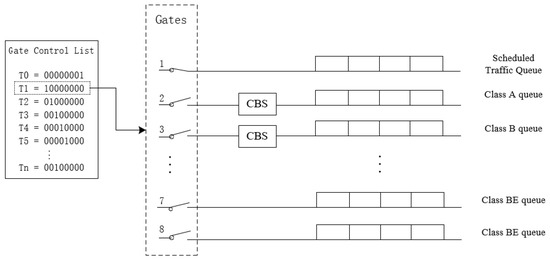
Figure 1.
Schematic diagram of scheduling based on time-aware shaping (TAS).
Vehicle audio and video information requires high real-time performance, so the data transmitted through the in-vehicle Ethernet system are usually set to high priority and have high bandwidth allocation, and are not affected by rate constrained (RC) traffic and best effort (BE) traffic interruption. The characteristic of RC traffic is to adjust the transmission rate of traffic according to the credit value assigned to each flow. Although RC traffic does not require strict real-time performance, the transmission is guaranteed to be completed within a certain period of time. For example, in sensor data or vehicle status information, credits are consumed or accumulated over time, and the transmission rate depends on the credit value of the flow and network conditions [19]. When the network is congested or resources are limited, the transmission rate of RC is limited to ensure reasonable utilization of resources. This is a flexible resource management mechanism, but the question of how to reasonably allocate credit values is a key issue, and factors such as the priority of each data, service quality requirements, and network congestion need to be taken into consideration.
BE traffic is mainly used in data transmission tasks that do not require the network to provide priority service quality assurance. Typical BE traffic includes file transfers and general application data. In BE transmission mode, network equipment does not perform special processing on transmitted data, nor does it guarantee the transmission rate, delay, or packet loss rate of data packets. The transmission performance of BE traffic fluctuates due to network congestion and bandwidth limitations. Since BE traffic can tolerate a certain degree of delay and packet loss, it is suitable for applications and services that have low real-time requirements. BE mode allows the network to allocate resources more flexibly to meet the transmission needs of various types of data while improving the overall efficiency of the network. After TAS meets the needs of ST and RC traffic, it uses the remaining bandwidth to transmit BE traffic. These data are transmitted in idle time slots to minimize interference to ST and RC traffic.
2.4. TSN Information Scheduling and Related Configuration
Through the combination of TSN/TAS protocol and IEEE 802.1Qav standard [20], the performance of automotive Ethernet is further improved. A credit based shaper algorithm is defined in the IEEE 802.1Qav standard to control data flow in the network and prevent network congestion. The CBS algorithm regulates the sending rate of packets by allocating a credit limit to each queue. A certain amount of credit is consumed when a packet is sent out of the queue. If the credit limit is exhausted the queue will stop sending data until the credit limit is restored. The rate of change of the credit limit is constrained by predefined parameters, which are configured according to network characteristics and service quality requirements [21]. This problem can be effectively solved by combining TAS with CBS. Create an ST schedule in TAS to ensure that RC and BE transmissions are not performed during ST transmission, thereby ensuring real-time and deterministic data transmission. During non-ST transmission periods, RC and BE are transmitted according to the CBS algorithm to effectively utilize the remaining bandwidth. The combination of TAS and CBS not only enhances the real-time nature of the network, but also ensures the transmission scheduling and management of different types of data, thus improving the performance and efficiency of the entire in-vehicle network.
In the IEEE 802.1Qbv [10] standard, guard band technology is introduced to prevent RC and BE traffic from overflowing into ST time slots. A guard band prohibiting data transmission is introduced before each ST slot, with a maximum frame size (MFS) set to 1500 bytes. By setting the guard band, the network adjusts the network status before the start of the ST time slot, thereby improving the reliability and real-time performance of the network. However, the guard band takes up a certain amount of bandwidth. In order to overcome this problem, IEEE 802.1Qbu [22] introduces a preemption mechanism, which allows the ongoing transmission of RC and BE traffic to be interrupted when needed, ‘preempts’ out-of-time slots for the transmission of ST traffic, and minimizes the length of the guard band, reducing its occupied bandwidth and improving network utilization [23,24].
3. Fixed Point Message Scheduling Algorithm
The basic framework of information scheduling is defined in the IEEE 802.1Qbv standard. Users schedule important messages according to actual communication needs, thereby ensuring that important messages are accurately transmitted within the specified time while minimizing end-to-end delays. This paper proposes a fixed point message scheduling (FPMS) algorithm. This algorithm uses the centralized network configuration (CNC) method to centrally manage the switches on the ST transmission path, allowing the switches to share information such as the length, priority, and period of the ST. Through centralized management, it is easier for administrators to monitor the status of the entire network and make necessary network adjustments and optimizations to ensure that real-time data have sufficient bandwidth and reduced latency.
3.1. FPMS Algorithm Principle
TSN strictly requires real-time and determinism, and the fixed point message scheduling algorithm focuses on two key factors, including message priority and length. To complete this, first construct a set of STs F, the total number of STs in F is n. Sort each element in F according to the priority and length of ST, ensuring that the priority of is not lower than the priority of , and the length of is not longer than the length of . This ensures that STs with a high priority and small length are transmitted first, meeting real-time requirements to the greatest extent.
The time window is the time required for each ST to transmit in the link. According to the fixed point message scheduling algorithm, a time window is allocated to each ST. ST transmits in the link according to the allocated time window, thereby ensuring the real-time and accurate ST transmission and avoiding frame interleaving and loss. The length of the time window is shown in Equation (1).
represents the length of the time window occupied by the i-th ST. Since the time windows belonging to the i-th ST have the same length, the time windows have the same length. represents the time window of the i-th ST that needs to be scheduled on the k-th link that needs to pass. represents the time window of the i-th ST that needs to be scheduled on the previous link of the k-th link.
The operation process of the fixed point message scheduling algorithm is shown in Figure 2. To complete this process, first calculate the least common multiple (LCM) T of all ST transmission periods. represents the transmission cycle of the sorted i-th ST, and i represents the number of STs that have completed scheduling in the schedule. represents the number of times needs to be transmitted in the super period T. In the super period, when transmits once, the value of m is counted up until the value of m is equal to Ni. Different from the traditional allocation method, the fixed point message scheduling algorithm allocates the available time window on the link to the data frame, which more intuitively reflects the delay experienced in data frame transmission and facilitates the calculation of delay. Li represents the total number of links that needs to pass through during transmission from the source sending node to the destination node. At the beginning of scheduling, the k value is equal to the Li value. k represents the number of links without time window allocation. Message scheduling starts from ST1, and the earliest available time window on the L1 link is assigned to ST1. Repeat the process of time window assignment for all the links between the destination node and the source node of ST1, and keep repeating this until the value of k decreases to 1.
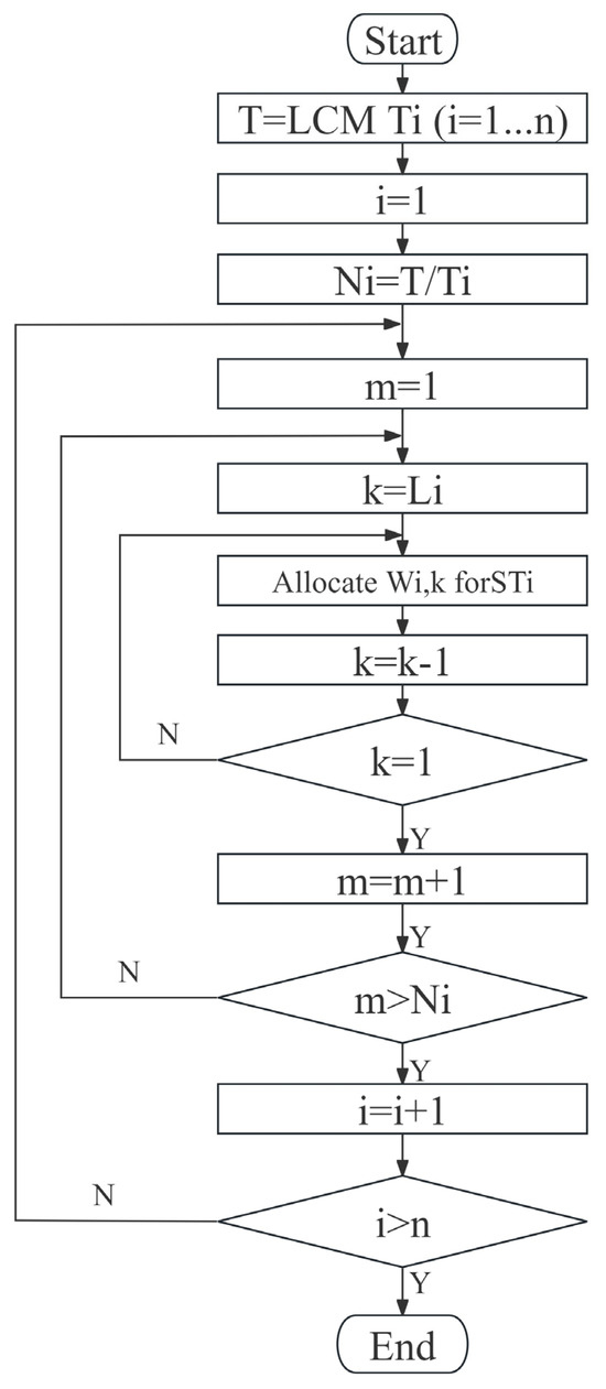
Figure 2.
Flowchart of fixed point message scheduling algorithm.
Each time all time windows are allocated to , the value of m is counted up. When the value of m exceeds the number of times Ni that needs to transmit in the super period T, the scheduling process of ends, and the value of i is incremented at the same time. By repeating the time window allocation process for when i is greater than n, all STs in flow set F complete the scheduling.
3.2. Time Window Allocation
In order to minimize the transmission delay of high-priority traffic, this paper sorts the traffic in the flow set. By providing an earlier time window to high-priority STs, high-priority STs have more flexible scheduling space than low-priority STs, thereby minimizing transmission delays. The allocation process of time windows is divided into two parts: sorting and allocation, as described in Algorithm 1. By constructing a link set, a good foundation is laid for the allocation of time windows. Among them, line 2 is the sorting part, which sorts the flow set to obtain the sorted flow set Fs. Select the first ST traffic allocation time window (line 4) in the flow set Fs.
| Algorithm 1 Fixed Point Message Scheduling Algorithm |
| Input: Time window W; flows set F; link K; constant k, t, i Output: Time window arrangement results |
| 1: link_set {} 2: Fs Sorting_the_flows(F); /* Input: Initial flows set F Output: Flows set after sorted Fs Fs sort F by f.pri from large to small and f.len from small to large return Fs */ 3: foreach STi ϵ Fs do 4: i = 1; 5: k = Li − 1; 6: repeat(n) 7: begin 8: begin 9: if ( > > … > ) 10: = earliest ; 11: else = 12: end 13: repeat (Li − 1) 14: begin 15: = latest ; 16: k = k − 1; 17: end 18: i = i + 1; 19: end 20: return Time window arrangement results |
Figure 3 is a schematic diagram of the allocation of time windows. The red dots indicate the fixed points determined by the FPSM algorithm. Blue dots indicate available time window starting points. When is transmitted from the source node to the destination node, it needs to pass through three links. In Figure 3a, the time window is the earliest available time window. It is guaranteed that there are idle time windows of the remaining two links before the time window. j is a non-negative integer less than h, and h is the total number of idle time windows that exist before the fixed point. Select the starting point of the time window as the fixed point , and its value is t0. In Figure 3b, the idle time window is selected as the available time window on the (Li − 1)-th link. In Figure 3c, for , the time window is not available, so continue to search for available time windows in the left direction. Finally, the idle time window is selected as the available time window on the (Li − 2)-th link.
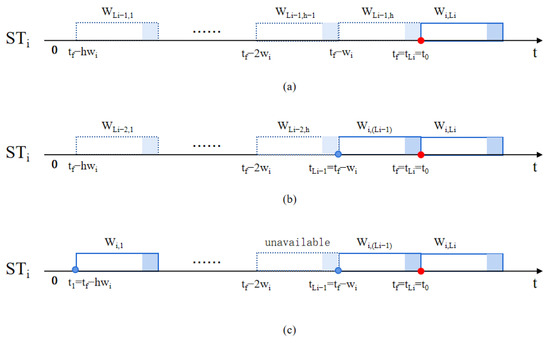
Figure 3.
Schematic diagram of time window allocation. (a) Select the available time window for , (b) select the available time window for , (c) select the available time window for .
Divide the time slot before t0 into h time windows, as shown in Equation (2).
The idle time windows are searched in order from the fixed point to the left, and the idle time window closest to the fixed point is used as the available time window. is the starting point of the k-th available time window, as shown in Equation (3). The value of k is a positive integer less than Li. When the value of k is Li − 1, is the fixed point .
4. Simulation Experiment
CANoe is a professional automotive network simulation and testing tool developed by the German company Vector Informatik GmbH (Stuttgart, Germany). CANoe is able to create virtual ECUs or network environments, allowing engineers to test without actual hardware. Due to its high degree of flexibility and powerful feature set, CANoe has become one of the indispensable test tools in the automotive industry [25]. To make the experimental results more realistic and believable, this study uses CANoe for simulation. In order to accurately reflect the communication requirements and message characteristics of real vehicles, this paper simulates the message interaction and message distribution between nodes in real vehicles based on the standard architecture provided by Renault, and designs the network topology shown in Figure 4. Through rigorous simulation testing, the performance of the algorithm in the vehicle network environment can be more accurately evaluated.
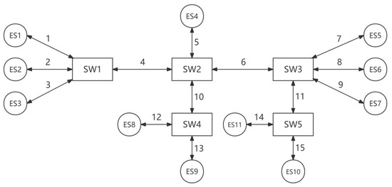
Figure 4.
Network topology architecture of in-vehicle Ethernet.
The network topology consists of 15 links (“1” to “15”), 5 switches (“SW1” to “SW5”) and 11 nodes (“ES1” to “ES11”). This includes 2 (functional) domain masters (ES1, ES5), 4 cameras (ES3, ES4, ES6, ES10), 2 displays (ES8, ES11), and 3 control units (ES2, ES7, ES9). The data transmission rate of all links is set to 100 Mbps in full-duplex mode.
STs were sorted according to the FPMS algorithm. The information parameters of the sorted ST are shown in Table 1. The selection of ST source node and destination node conforms to the real function of each node in the network and the real load rate of each transmission link. The priority, length, and cycle of ST conform to the categories and typical characteristics of real traffic.

Table 1.
Information parameters of ST.
Figure 5 is a message scheduling comparison table between the FPMS algorithm and the priority-only scheduling algorithm. Among them, Figure 5a is a schematic diagram of ST scheduling after applying the FPMS-based algorithm. Figure 5b is a schematic diagram of ST scheduling after applying the priority-only scheduling method. Obviously, the transmission delay caused by the priority-only scheduling method is unacceptable for low-priority STs. The ST transmission delay is basically kept to a minimum. Furthermore, by comparing ST6 in Figure 5a,b, it can be observed that the FPMS algorithm not only reduces the transmission delay of ST6, but also advances the transmission time of ST6. This is because the time when ST transmission ends on the link is after the fixed point determined by the FPMS algorithm. The FPMS algorithm makes the available time windows concentrated near the fixed point. At the same time, it does not affect the end time of message transmission, frees up an earlier idle time window, and provides it for lower priority messages.
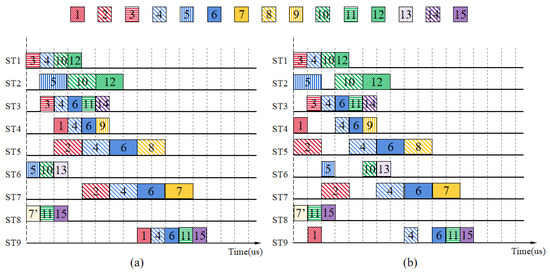
Figure 5.
Schematic diagram of message scheduling of FPMS algorithm and priority-only scheduling algorithm. (a) Schematic diagram of message scheduling of FPMS algorithm; (b) schematic diagram of message scheduling of priority-only scheduling algorithm.
Table 2 is an end-to-end simulation result diagram based on the FPMS algorithm and the priority-only scheduling algorithm. The experimental results show that the delay times of ST1, ST3, and ST8 of the two algorithms are the same, and the delay times of ST2, ST4, ST5, ST6, ST7, and ST9 based on the FPMS algorithm are lower than the delay time of the priority-only scheduling algorithm.
Table 2.
End-to-end delay simulation results.
The differences between the two algorithms can be more clearly visualized in Figure 6. In conclusion, the FPMS algorithm proposed in this study results in a 66% reduction in ST end-to-end delay time in the network compared to the pure priority scheduling algorithm.
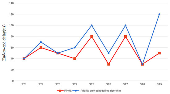
Figure 6.
End-to-end delay simulation results.
5. Discussion
Without networking on the vehicle, the control system of a car is an independent local network system, and the bus system and communication data of the car are relatively safe. However, with the ever-accelerating process of automotive electronics and automation, most vehicles are now equipped with ADAS, entertainment systems, automatic parking systems, and so on. Although connecting smart phones, Bluetooth, the Internet, and other network systems to the driver has improved driving pleasure and convenience, it also brought hacker attacks, security holes, and other non-negligible automotive network security issues, seriously affecting the safety of the car driving, personal privacy, and even jeopardized public safety. The vehicle bus network system is no longer a stand-alone, secure network system. Therefore, security mechanisms are needed to improve the security of vehicle bus network systems.
It is important to note that these security mechanisms can cause additional delays when a switch or node receives and sends information. Examples include delays in processing frames after they have been fully received at the switch MAC input port, delays in “filtering” frames after they have been captured at the receiving end, and so on [26,27]. For this delay, the FPMS algorithm is not different from other algorithms of the same type. The FPMS algorithm is not only efficient, but also simple and does not require a lot of mathematical operations. Therefore, the FPMS algorithm, combined with existing traffic shaping mechanisms and security mechanisms, will not cause additional adverse effects in the network.
6. Conclusions
This paper focuses on the real-time message transmission problem of in-vehicle Ethernet in intelligent connected cars, and innovatively proposes a fixed point message scheduling algorithm (FPMS) based on a time-sensitive network (TSN). Through simulation experiments, compared with the simple priority scheduling algorithm, the FPMS algorithm proposed in this study reduces the end-to-end delay of 66% of the STs, which shows superior performance and is of practical value for optimizing the real-time communication performance of in-vehicle Ethernet. The fixed point message scheduling algorithm can be applied to a variety of network scenarios and the simulation of end-to-end delays. The real-time nature and accuracy of high-priority STs are ensured and end-to-end delay is reduced by prioritization and time window allocation. The work in this paper provides a highly efficient solution for the communication network design of intelligent connected vehicles, and is expected to promote the development of in-vehicle communication technology and improve the performance of intelligent connected vehicles.
Author Contributions
Writing—original draft preparation, J.C., Q.Z., Y.X. (Yihu Xu), Y.W., W.J. and Y.X. (Yinan Xu). All authors have read and agreed to the published version of the manuscript.
Funding
This research was supported by National Natural Science Foundation of China under Grants 62161049 and 61763047.
Data Availability Statement
Data are contained within the article.
Conflicts of Interest
The authors declare no conflicts of interest.
Abbreviation
| TSN | Time-Sensitive Network |
| TAS | Time-Aware Shaper |
| GCL | Gate Control List |
| CBS | Credit Based Shaper |
| ST | Schedule Traffic |
| RC | Rate Constrained Traffic |
| BE | Best Effort Traffic |
| MFS | Maximum Frame Size |
| CNC | Centralized Network Configuration |
References
- Peng, Y.; Shi, B.; Jiang, T.; Tu, X.; Xu, D.; Hua, K. A Survey on In-Vehicle Time-Sensitive Networking. IEEE Internet Things J. 2023, 10, 14375–14396. [Google Scholar] [CrossRef]
- Zhu, H.; Zhou, W.; Li, Z.; Li, L.; Huang, T. Requirements-Driven Automotive Electrical/Electronic Architecture: A Survey and Prospective Trends. IEEE Access 2021, 9, 100096–100112. [Google Scholar] [CrossRef]
- Ji, B.; Zhang, X.; Mumtaz, S.; Han, C.; Li, C.; Wen, H.; Wang, D. Survey on the Internet of Vehicles: Network Architectures and Applications. IEEE Commun. Stand. Mag. 2020, 4, 34–41. [Google Scholar] [CrossRef]
- Liu, X.; Nie, Z.; Li, D.; Yu, H. Design of An Improved Ethernet AVB Model for Real-time Communication in In-Vehicle Network. In Proceedings of the 2019 IEEE 3rd Information Technology, Networking, Electronic and Automation Control Conference (ITNEC), Chengdu, China, 15–17 March 2019. [Google Scholar]
- Luo, F.; Wang, B.; Fang, Z.; Yang, Z.; Jiang, Y. Security Analysis of the TSN Backbone Architecture and Anomaly Detection System Design Based on IEEE 802.1 Qci. Secur. Commun. Netw. 2021, 2021, 6902138. [Google Scholar] [CrossRef]
- Lo Bello, L.; Patti, G.; Leonardi, L. A perspective on ethernet in automotive communications—Current status and future trends. Appl. Sci. 2023, 13, 1278. [Google Scholar] [CrossRef]
- Khatri, N.; Shrestha, R.; Nam, S.Y. Security Issues with In-Vehicle Networks, and Enhanced Countermeasures Based on Blockchain. Electronics 2021, 10, 893. [Google Scholar] [CrossRef]
- Xu, Y.; Shang, J.; Tang, H. Recent Trends of In-Vehicle Time Sensitive Networking Technologies, Applications and Challenges. China Commun. 2023, 20, 30–55. [Google Scholar] [CrossRef]
- Bello, L.L.; Steiner, W. A Perspective on IEEE Time-Sensitive Networking for Industrial Communication and Automation Systems. Proc. IEEE 2019, 107, 1094–1120. [Google Scholar] [CrossRef]
- IEEE Std 802.1Qbv-2015; IEEE Standard for Local and Metropolitan Area Networks—Bridges and Bridged Networks—Amendment 25: Enhancements for Scheduled Traffic. Institute of Electrical and Electronics Engineers (IEEE): Piscataway, NJ, USA, 18 March 2016; 57p.
- IEEE Std 802.1AS-2011; IEEE Standard for Local and Metropolitan Area Networks—Timing and Synchronization for Time-Sensitive Applications in Bridged Local Area Networks. Institute of Electrical and Electronics Engineers (IEEE): Piscataway, NJ, USA, 30 March 2011; 292p.
- IEEE Std 802.1Qcc-2018; IEEE Standard for Local and Metropolitan Area Networks—Bridges and Bridged Networks—Amendment 31: Stream Reservation Protocol (SRP) Enhancements and Performance Improvements. Institute of Electrical and Electronics Engineers (IEEE): Piscataway, NJ, USA, 31 October 2018; 208p.
- Stüber, T.; Osswald, L.; Lindner, S.; Menth, M. A Survey of Scheduling Algorithms for the Time-Aware Shaper in Time-Sensitive Networking (TSN). IEEE Access 2023, 11, 61192–61233. [Google Scholar] [CrossRef]
- Vlk, M.; Hanzálek, Z.; Brejchová, K.; Tang, S.; Bhattacharjee, S.; Fu, S. Enhancing Schedulability and Throughput of Time-Triggered Traffic in IEEE 802.1 Qbv Time-Sensitive Networks. IEEE Trans. Commun. 2020, 68, 7023–7038. [Google Scholar] [CrossRef]
- Zhou, Z.; Lee, J.; Berger, M.S.; Park, S.; Yan, Y. Simulating TSN Traffic Scheduling and Shaping for Future Automotive Ethernet. J. Commun. Netw. 2021, 23, 53–62. [Google Scholar] [CrossRef]
- Yuan, Y.; Cao, X.; Liu, Z.; Chen, C.; Guan, X. Adaptive Priority Adjustment Scheduling Approach with Response-Time Analysis in Time-Sensitive Networks. IEEE Trans. Ind. Inform. 2022, 18, 8714–8723. [Google Scholar] [CrossRef]
- Chahed, H.; Kassler, A. TSN Network Scheduling-Challenges and Approaches. Network 2023, 3, 585–624. [Google Scholar] [CrossRef]
- Zhao, L.; Pop, P.; Steinhorst, S. Quantitative Performance Comparison of Various Traffic Shapers in Time-Sensitive Networking. IEEE Trans. Netw. Serv. Manag. 2022, 19, 2899–2928. [Google Scholar] [CrossRef]
- Zhao, L.; Pop, P.; Zheng, Z.; Li, Q. Timing Analysis of AVB Traffic in TSN Networks Using Network Calculus. In Proceedings of the 2018 IEEE Real-Time and Embedded Technology and Applications Symposium (RTAS), Porto, Portugal, 11–13 April 2018. [Google Scholar]
- IEEE Std 802.1Qav-2009; IEEE Standard for Local and Metropolitan area Networks—Virtual Bridged Local Area Networks Amendment 12: Forwarding and Queuing Enhancements for Time-Sensitive Streams. Institute of Electrical and Electronics Engineers (IEEE): Piscataway, NJ, USA, 5 January 2010; 72p.
- Wang, X.; Yao, H.; Mai, T.; Xiong, Z.; Wang, F.; Liu, Y. Joint routing and scheduling with cyclic queuing and forwarding for time-sensitive networks. IEEE Trans. Veh. Technol. 2022, 72, 3793–3804. [Google Scholar] [CrossRef]
- IEEE Std 802.1Qbu-2016; IEEE Standard for Local and Metropolitan Area Networks—Bridges and Bridged Networks—Amendment 26: Frame Preemption. Institute of Electrical and Electronics Engineers (IEEE): Piscataway, NJ, USA, 2016; 50p.
- Jiang, J.; Li, Y.; Zhang, X.; Yu, M.; Lee, C.D.; Hong, S.H. Assessing the Traffic Scheduling Method for Time-Sensitive Networking (TSN) by Practical Implementation. J. Ind. Inf. Integr. 2023, 33, 100464. [Google Scholar] [CrossRef]
- Kobzan, T.; Schriegel, S.; Althoff, S.; Boschmann, A.; Otto, J.; Jasperneite, J. Secure and Time-Sensitive Communication for Remote Process Control and Monitoring. In Proceedings of the 2018 IEEE 23rd International Conference on Emerging Technologies and Factory Automation (ETFA), Turin, Italy, 4–7 September 2018. [Google Scholar]
- Naik, K.; Pol, R.; Dandawate, Y.; Kulkarni, S. Passenger Ground Vehicle Live Parameter Monitoring and Governing Using Automotive IVN Prototype Model. EPH-Int. J. Sci. Eng. 2019, 5, 36–43. [Google Scholar] [CrossRef]
- Deng, L.; Xie, G.; Liu, H.; Han, Y.; Li, R.; Li, K. A survey of real-time ethernet modeling and design methodologies: From AVB to TSN. ACM Comput. Surv. (CSUR) 2022, 55, 1–36. [Google Scholar] [CrossRef]
- Carnevale, B.; Falaschi, F.; Crocetti, L.; Hunjan, H.; Bisase, S.; Fanucci, L. An implementation of the 802.1 AE MAC Security Standard for in-car networks. In Proceedings of the 2015 IEEE 2nd World Forum on Internet of Things (WF-IoT), Milan, Italy, 14–16 December 2015. [Google Scholar]
Disclaimer/Publisher’s Note: The statements, opinions and data contained in all publications are solely those of the individual author(s) and contributor(s) and not of MDPI and/or the editor(s). MDPI and/or the editor(s) disclaim responsibility for any injury to people or property resulting from any ideas, methods, instructions or products referred to in the content. |
© 2024 by the authors. Licensee MDPI, Basel, Switzerland. This article is an open access article distributed under the terms and conditions of the Creative Commons Attribution (CC BY) license (https://creativecommons.org/licenses/by/4.0/).