Article

Bidirectional Chaotic Synchronization Communication of Closed-Loop Mutually Coupled Nano-Lasers

1
School of Physics and Electronic Information, Yantai University, Yantai 264005, China
2
FISEC Infomation Technology Company Limited, Weihai 264200, China
*
Author to whom correspondence should be addressed.
Electronics 2024, 13(1), 239; https://doi.org/10.3390/electronics13010239
Submission received: 16 December 2023 / Revised: 3 January 2024 / Accepted: 3 January 2024 / Published: 4 January 2024

Abstract

:
It is well known that the dynamical characteristics of nano-lasers (NLs) have been extensively studied, but there is limited research on chaotic synchronization communication. In this paper, we propose a closed-loop system of mutually coupled NLs. Firstly, the autocorrelation function is employed to evaluate the capability of the system to conceal the time-delayed signature (TDS), and then, based on this, we specifically analyze the effects of the injection strength, frequency detuning, and parameter mismatch of two NLs on the chaotic synchronization performance, as well as the bidirectional communication. The detailed studies indicate that the proposed closed-loop mutually coupled system based on NLs can achieve high-quality chaotic synchronization with a low TDS and large bandwidth. In addition, the system maintains high-quality chaotic synchronization and communication performance even under significant parameter mismatch.

1. Introduction

Semiconductor lasers (SLs) are widely used in optical fiber communication and are one of the most common light sources. It is well accepted that these lasers can exhibit rich nonlinear dynamics by introducing additional degrees of freedom. With the reasonable choice of control parameters, they are prone to generate chaotic optical signals with a low time-delay signature (TDS) and wide bandwidth, which can be widely used in important fields such as chaotic secure communication [1,2,3,4,5], chaotic radar [6,7], neural computing [8,9], compressive sensing [10], reservoir computing [11], and high-speed physical random number generation [12,13]. In particular, a necessary condition for implementing secure optical chaotic communication is the achievement of good chaotic synchronization between the SLs at the transmitter and receiver. Message transmission based on chaotic synchronization refers to the encoding of a useful message into chaotic carriers using methods such as chaos masking (CMS), chaos shift keying (CSK), and chaos modulation (CM). This encoded message is then transmitted through the transmission channel to the receiver. At the receiver, the useful message is recovered using the chaotic filtering effect [14].
Therefore, chaotic synchronization and secure communication based on SLs have become a focal point of research for many scholars. So far, research has primarily focused on unidirectional coupling [15,16,17] or bidirectional coupling between SLs [18,19,20,21,22,23,24,25,26], as well as configurations involving coupled SLs forming circular or network topologies [27,28,29,30]. Unlike master–slave systems, the outputs of mutually coupled systems synchronize under a symmetric operation mechanism, which requires that the lasers and external optical injection should be identical. On the other hand, mutually coupled systems, due to their higher security and potential for bidirectional data transmission, have been widely explored. For example, Chiang et al. theoretically demonstrated the general synchronization conditions for a system of mutually coupled SLs with feedback and experimentally verified them using optoelectronic feedback schemes [21]. Vicente et al. proposed a scheme for complete synchronization between two mutually coupled SLs with a partially transparent mirror in the middle, and discussed its potential applications in simultaneous bidirectional message transmission [22]. Subsequently, Jiang et al. further explored chaotic synchronization and its applications in the multi-channel communication of external optical feedback mutually coupled semiconductor lasers (EOF-MCSLs) [24], external optical injection mutually coupled semiconductor lasers (EOI-MCSLs) [25], and high-frequency chaotic-state multi-time-delay mutually coupled external-cavity semiconductor lasers (MTDMC-ECSLs) [26]. The study results demonstrated that the EOF-MCSLs system exhibits high security. In addition, enhancing the synchronization communication security of the system can be achieved by appropriately increasing the information rate, adopting an asymmetric rate information transmission method, and monitoring the synchronization performance at both the transmitter and receiver. Compared with the EOF-MCSL system, the EOI-MCSL system indicates a strong parameter-mismatch robustness and frequency-detuning tolerance in real-time chaotic synchronization. This means that the EOI-MCSL system achieves higher security in bidirectional synchronous communication. Finally, the multi-channel chaotic communication based on MTDMC-ECSLs greatly enhances the communication capacity between two SLs, providing important guidance for realizing chaotic communication networks. In recent years, Jiang et al. proposed a scheme using dynamically synchronized SLs that are subject to a common dual injection from two mutually coupled SLs. Based on this, they realized a new secure key distribution approach, and this innovative method has achieved high-quality chaotic secure optical communication [31]. The research on the above-mentioned mutually coupled systems has all utilized traditional SLs, while synchronous communication using nano-lasers (NLs), which exhibit faster response times and a lower power consumption and are more easily integrated, has not been adequately explored. In a previous work, we achieved chaotic synchronization for secure communication using a unidirectional injection system with NLs [17]. Therefore, in this context, it is appropriate to study the chaotic synchronization and bidirectional communication of mutually coupled NL systems to determine whether such systems can offer new capabilities in the context of photonic integrated circuits (PICs).
It has been found that external-cavity SLs can provide higher security for communication systems and are integral components of chaotic secure communication systems. However, in this case, many scholars have found that laser chaotic communication systems have security vulnerabilities. This is because the process of generating chaotic signals through external optical feedback or external optical injection into SLs inevitably introduces periodicity, known as TDS [32]. The periodicity in the signals can degrade the performance of chaos-based applications. For instance, the presence of time-delay information poses a risk of information leakage, as eavesdroppers can extract transmission signal time-delay information from chaotic signals using time-series analysis techniques such as autocorrelation function (ACF) [32], delay mutual information (DMI) [33], permutation entropy (PE) [34], etc. Consequently, eavesdroppers can obtain the key parameters of the communication system and threaten the security of chaotic secure communication systems by reproducing chaotic secure systems using reconstruction techniques [35]. Therefore, how to conceal TDS in the system is also a hot topic for researchers. In recent years, many published papers have proposed various schemes to reduce or even eliminate TDS [36,37,38,39,40,41,42,43]. On the one hand, complex feedback schemes are considered in the system, i.e., adding multiple feedback paths. On the other hand, multiple injection paths are added, or another SL is introduced, all of which increase the complexity of the system so that the TDS can be concealed over a larger parameter range. Recently, we have completed work on the concealment of the TDS in the open-loop structure, semi-open-loop structure, and closed-loop structure of mutually coupled NLs [44]. The simulation results suggest that, compared to the open-loop and semi-open-loop structures, the closed-loop structure performs better in concealing TDS, almost achieving TDS concealment across the entire parameter plane.
Hence, in this paper, we investigate the chaotic synchronization and bidirectional communication of optical feedback mutually coupled NLs. The paper is organized as follows: in Section 2, the model of closed-loop mutually coupled NLs and the corresponding rate equations are presented in detail. The simulation results are given in Section 3, based on TDS concealment, which focuses on the impact of internal parameters and system parameters on chaotic synchronization and bidirectional communication. Finally, we draw our key conclusions in Section 4.

2. Theoretical Model

The structure of the closed-loop mutually coupled NL system is illustrated in Figure 1. In particular, NL1 and NL2 are bidirectionally coupled through a common channel, and each of them receives two signals: one is its own feedback optical signal, and the other is the injection signal from the opposite NL. Thus, the dynamic characteristics of NL1 and NL2 are jointly determined by these two signals. Additionally, it is noteworthy that NL1 and NL2 operate symmetrically, so they allow for high-quality chaotic synchronization. In this system, the two opposite-direction channels on the common link can be easily separated by a fiber coupler (FC), facilitating duplex communication between NL1 and NL2 (both can serve as both transmitter and receiver simultaneously). Furthermore, the system message security can be further enhanced because the messages are transmitted simultaneously over a common link [22]. For the coding and decoding of messages in this system, the differences between two photodetectors (PDs) are first compared. Then, high-frequency components are eliminated through a Butterworth low-pass filter (LPF), and finally, the transmitted message can be accurately recovered.
The rate equations for the proposed system are [44,45,46]:
d S 1 , 2 t d t = Γ F β N 1 , 2 t τ n + g n N 1 , 2 t N 0 1 + ε S 1 , 2 t 1 τ p S 1 , 2 t   + 2 k r 1 , 2 S 1 , 2 t S 2 , 1 t t r cos θ 1 , 2 t + 2 k d 1 , 2 S 1 , 2 t S 1 , 2 t t d cos θ 3 , 4 t
d N 1 , 2 t d t = I 1 , 2 e V b N 1 , 2 t τ n F β + 1 β g n N 1 , 2 t N 0 1 + ε S 1 , 2 t S 1 , 2 t
d ϕ 1 , 2 t d t = α 2 Γ g n N 1 , 2 t N t h ± Δ ω k r 1 , 2 S 2 , 1 t t r S 1 , 2 t sin θ 1 , 2 t   k d 1 , 2 S 1 , 2 t t d S 1 , 2 t sin θ 3 , 4 t
θ 1 , 2 t = ± Δ ω t + 2 π f 2 , 1 t r + ϕ 1 , 2 t ϕ 2 , 1 t t r
θ 3 , 4 t = 2 π f 1 , 2 t d + ϕ 1 , 2 t ϕ 1 , 2 t t d
where S t is the photon density, N t is the carrier density, and ϕ t is the phase. In these equations, the subscripts ‘1’ and ‘2’ stand for NL1 and NL2, respectively. In this structure, the Purcell factor F, the spontaneous emission coupling factor β, and the bias current I I = 2 I t h are key internal parameters, where I t h is the threshold current. Some other parameters within the system are the confinement factor Γ , the differential gain g n , the gain saturation factor ε and the linewidth enhancement factor α , the transparent carrier density N 0 , the threshold carrier density N t h N t h = N 0 + 1 / Γ τ p g n , the electron charge e, the volume of the active region V b ; τ n and τ p are the carrier lifetime and photon lifetime, respectively. Δ ω Δ ω = 2 π Δ f , Δ f = f 1 f 2 denotes the angular frequency detuning between NL1 and NL2, where Δ f represents the frequency detuning.
It is important to note that the last term in Equations (1) and (3) stands for the feedback term. The term contains both the feedback delay td and the feedback strength kd, and the expression for kd can be formulated as [46]:
k d = f 1 R R e x t R c 2 n L
where f denotes the feedback coefficient, R represents the cavity surface reflectivity of NLs, R e x t is the mirror reflectivity, c stands for the speed of light, n is the refractive index, and L is the length of the feedback cavity. Similarly, in Equations (1) and (3), the penultimate term stands for the injection term, where kr and tr are the injection strength and injection delay of the injection path, respectively. Here, R i n j is the injection ratio, and its calculation formula is written as [46]:
k r = 1 R R i n j R c 2 n L
In this study, we employ the fourth-order Runge–Kutta method to numerically solve Equations (1)–(5). We assumed that the internal parameters of NL1 and NL2 are identical in the system, and noise effects are neglected in the simulations. Noise encompasses both the noise from the NLs and the noise from the detection chain. It is well known that under the injection scheme, the injection delay (tr) has minimal impact on the dynamic characteristics of the laser output. Therefore, we assume tr = 0 in the following study. Table 1 lists numerical values for some key parameters used in the simulations.
To quantitatively assess TDS in numerical terms, we utilize the efficient autocorrelation function (ACF). In the following analysis, we consider that TDS is effectively concealed when the peak value of the ACF is less than 0.2. We express the ACF function using the following equation [32]:
C Δ t = I t + Δ t I t + Δ t I t I t I t + Δ t I t + Δ t 2 I t I t 2
where denotes the average value of the time series, and Δ t stands for the lag time. On the other hand, this paper primarily analyzes the synchronization performance of chaotic outputs from the two NLs in the system. To quantify the correlation between NL1 and NL2, we employ the cross-correlation function (CCF), and the defined correlation coefficient is [47]:
C 12 Δ t = I 1 t + Δ t I 1 t + Δ t I 2 t I 2 t I 1 t + Δ t I 1 t + Δ t 2 I 2 t I 2 t 2
where Δ t stands for the displacement between the two chaotic time series, and is the time average. The subscripts ‘1’ and ‘2’ represent NL1 and NL2, respectively. It should be noted that when |C| = 1, NL1 and NL2 achieve complete synchronization, while there is no correlation between the two lasers when |C| = 0. In this paper, we consider that high-quality chaotic synchronization between NL1 and NL2 is achieved when |C| > 0.95.

3. Numerical Results

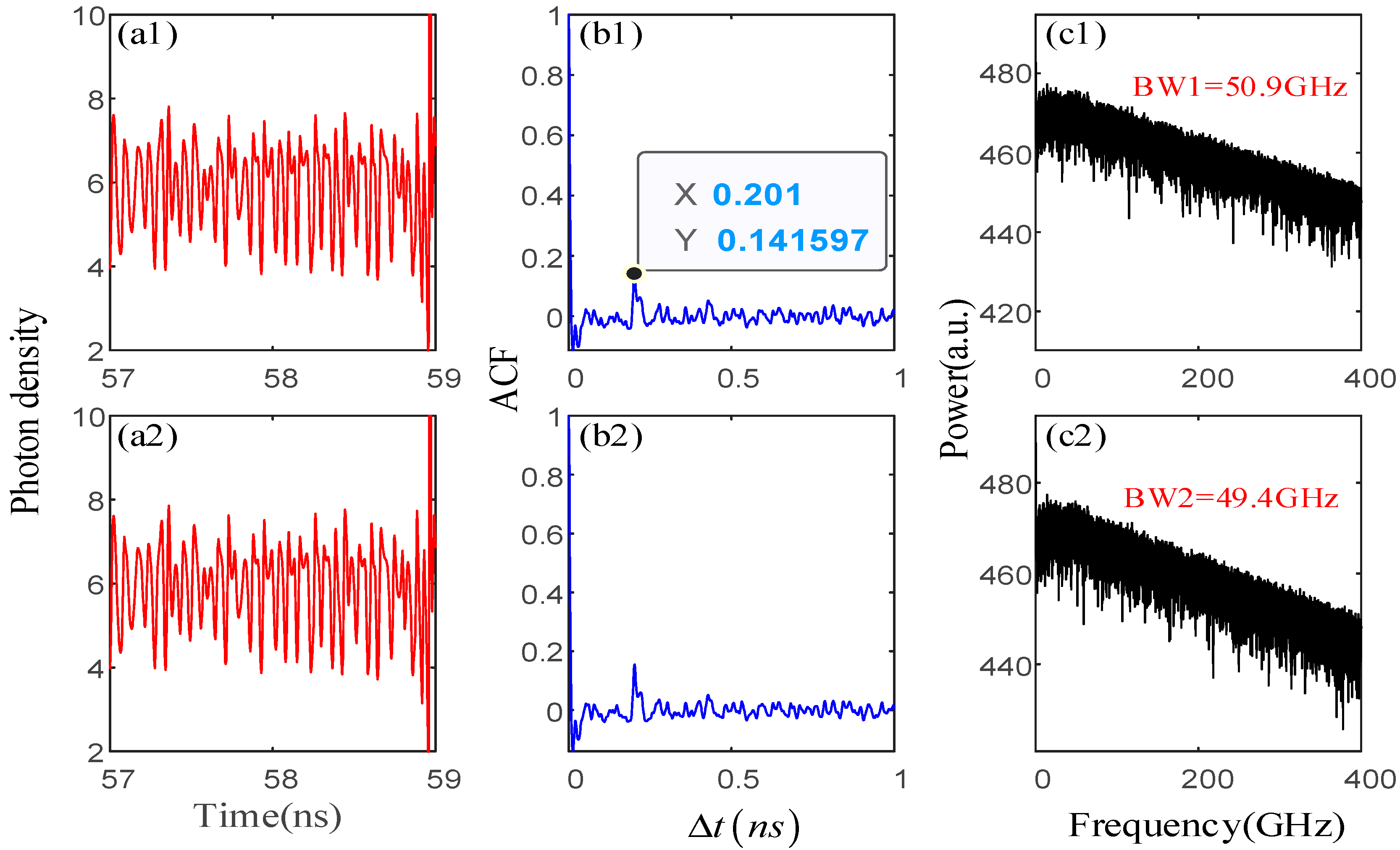
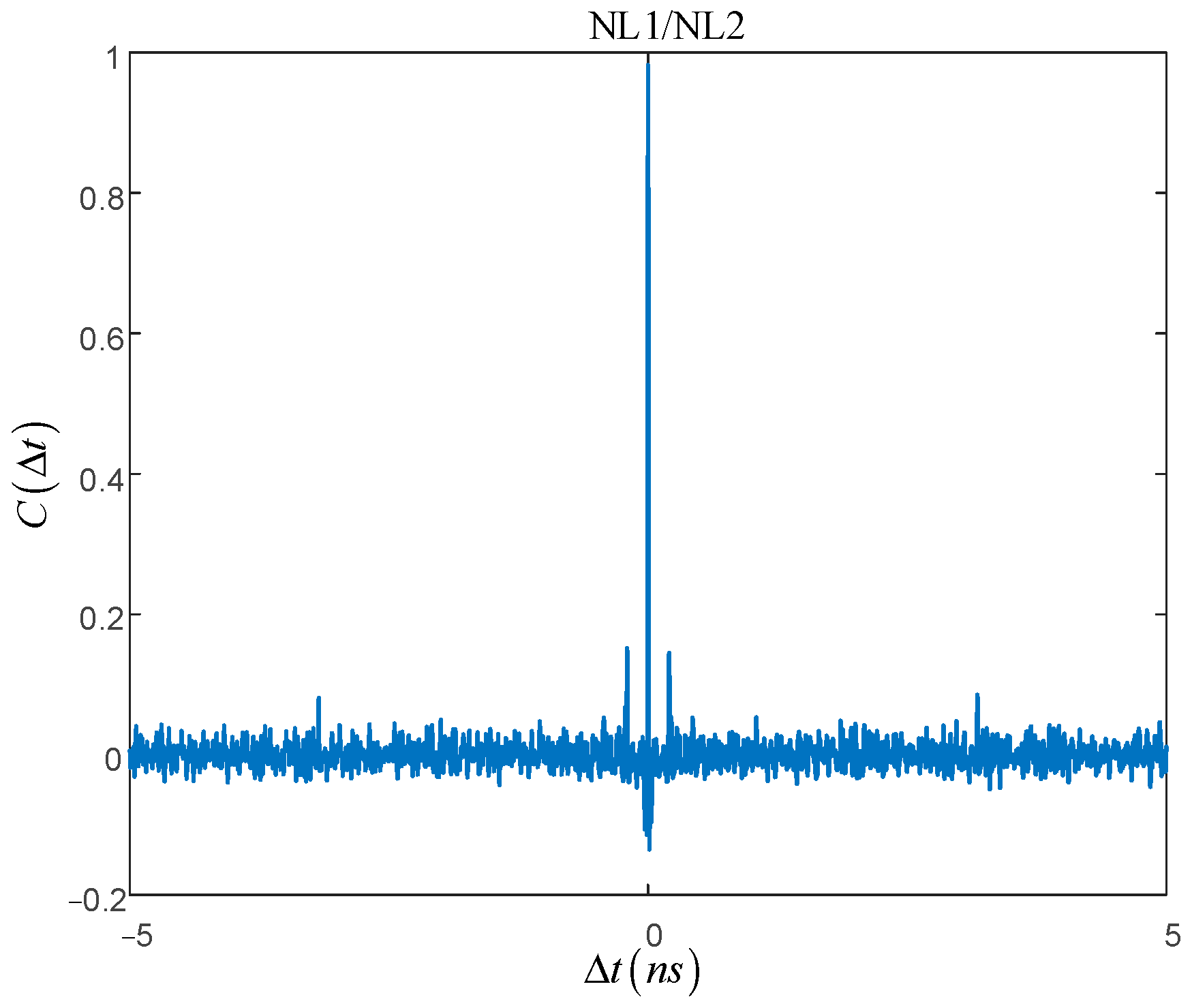
In this section, we firstly consider the TDS in the closed-loop mutually coupled NL system. Figure 2 displays the chaotic time series, ACF, and power spectrum plots for NL1 and NL2. The system parameters between NL1 and NL2 are set as follows: the feedback coefficient f1 = f2 = 0.01, k r 1 = k r 2 = 250   n s 1 , and Δ f = 25 GHz . In addition, F = 14, β = 0.05, I = 2Ith, and Ith = 1.1 mA. Under these parameter settings, it can be clearly observed that the maximum peak value of the ACF is 0.14, indicating that TDS is effectively concealed, as shown in Figure 2(b1,b2). This suggests that the chaotic behavior of the system has been optimized. What is more, from the power spectra in Figure 2(c1,c2), it can be seen that the power spectra of NL1 and NL2 are remarkably flat under the mentioned parameters, and the bandwidths of NL1 and NL2 are 50.9 and 49.4 GHz, respectively. This result indicates that in the structure of bidirectional synchronous communication, both NLs can achieve chaotic bandwidth. In other words, NL1 and NL2 can facilitate high-speed message transmission, which lays the foundation for subsequent bidirectional synchronous communication. On the other hand, NL1 and NL2 not only exhibit similar ACF curves but also have very similar chaotic time series. Building upon this, the chaotic synchronization between NL1 and NL2 is investigated, as shown in Figure 3. As can be seen, the maximum correlation coefficient C 12 at the injection delay of NL1 and NL2 exceeds 0.95, which results in high-quality chaotic synchronization.
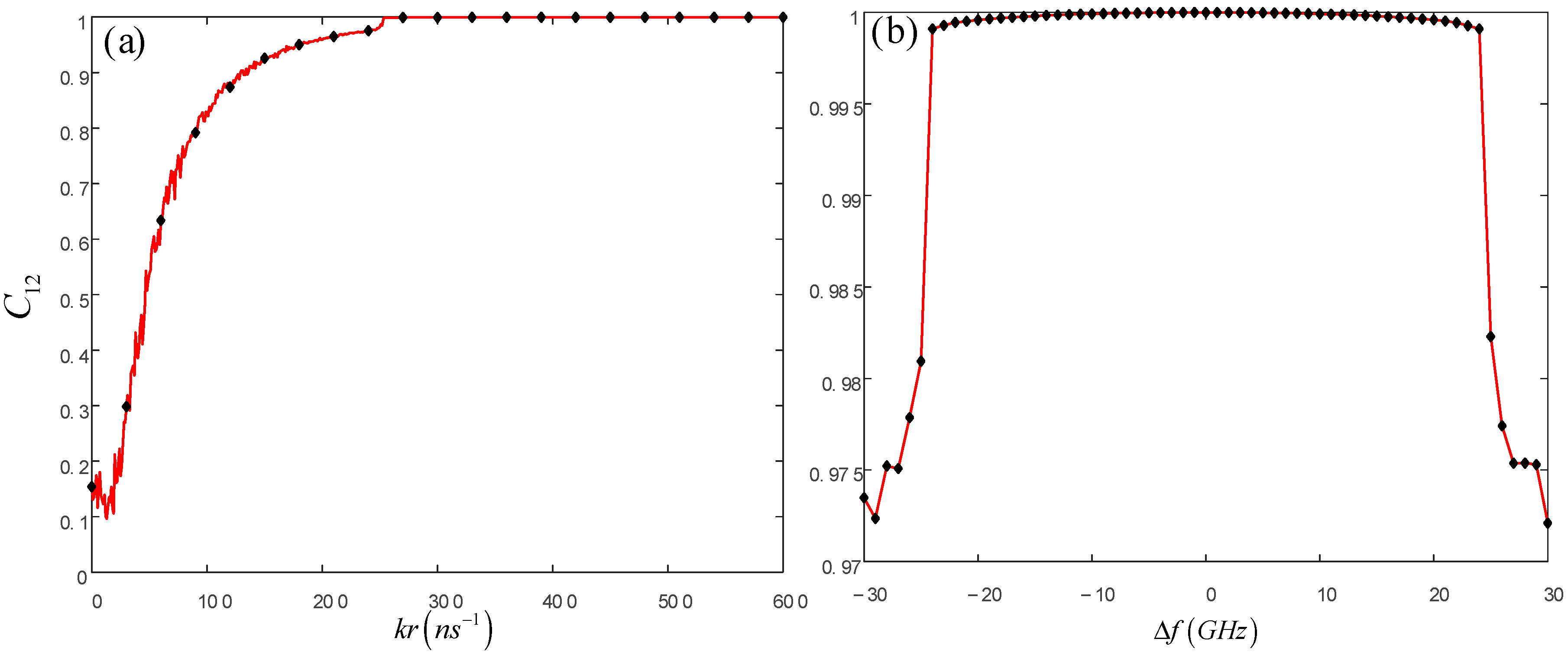
To this end, in order to discuss the effects of injection strength and frequency detuning on the chaotic synchronization performance of a closed-loop mutually coupled NL system, Figure 4 illustrates the C 12 with respect to the injection strength kr and frequency detuning Δ f . From Figure 4a, it can be seen that C 12 gradually increases with the gradual increase in kr. When 180   n s 1 < k r < 253   n s 1 , C 12 > 0.95, which confirms the achievement of high-quality chaotic synchronization between NL1 and NL2. As kr is further increased to and beyond 253 n s 1 , NL1 and NL2 achieve complete chaotic synchronization due to the significant injection strength leading to injection-locking effects. From a physical point of view, this is attributed to the injection-locking effect caused by an excessively high injection intensity between the two lasers. In this case, injection-locking synchronization makes use of this effect, resulting in the nonlinear output of the lasers behaving identically to the master laser. In turn, when k r = 250   n s 1 , chaotic synchronization is maintained over the entire range of Δ f = [−30, 30], symmetrically about Δ f = 0. Our results show that Δ f has a relatively minor impact on achieving chaotic synchronization in the optically feedback mutually coupled NL system as shown in Figure 4b; this is because frequency detuning has a relatively minor impact on injection locking.
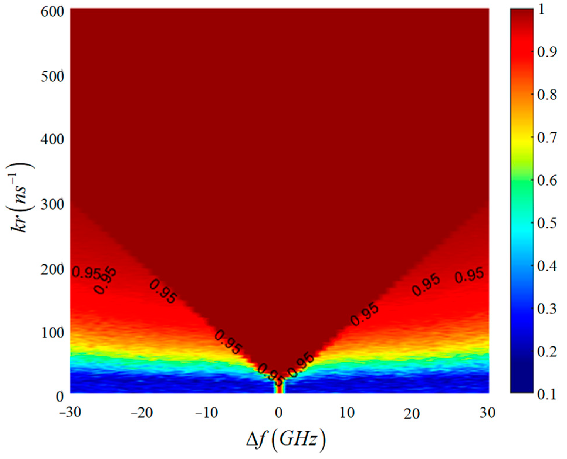
With the guidance presented in Figure 4, we present Figure 5 to further explain the distribution pattern of chaotic synchronization. The horizontal axis of the graph represents the frequency detuning, while the vertical axis represents the injection strength. From Figure 5, it is evident that the results of C 12 change with simultaneous variations in kr and Δf. Specifically, the chaotic synchronization is symmetric about Δ f = 0, and when kr is greater than approximately 200 n s 1 , C 12 exceeds 0.95. Subsequently, as kr gradually increases, chaotic synchronization is achieved throughout the entire plane. On the other hand, C 12 changes when Δf > 20 GHz, but this change is small, which is due to the fact that the larger injection intensity causes the laser to have an injection-locking effect, but the frequency detuning has a smaller effect on the injection locking. This conclusion aligns with the findings in Figure 4.
For the results obtained above, all parameters of NL1 and NL2 are assumed to be perfectly identical. However, in practical applications, parameter mismatches in chaotic synchronization systems are inevitable. Therefore, it is necessary to investigate the mismatch robustness of the system. For convenience, the parameters of NL1 are kept constant, while those of NL2 are altered. In this paper, we consider five key parameters: the linewidth enhancement factor α , the photon lifetime τ p , the carrier lifetime τ n , the differential gain g n , and the transparent carrier density N 0 . Changing their values will directly impact the synchronization performance. To this end, the parameter mismatch ratio μ is defined as follows [47]:
μ = Π N L 1 Π N L 2 Π N L 1
where Π can take values such as α , τ p , τ n , g n , and N 0 ; the other parameters of NL1 and NL2 have been given above.
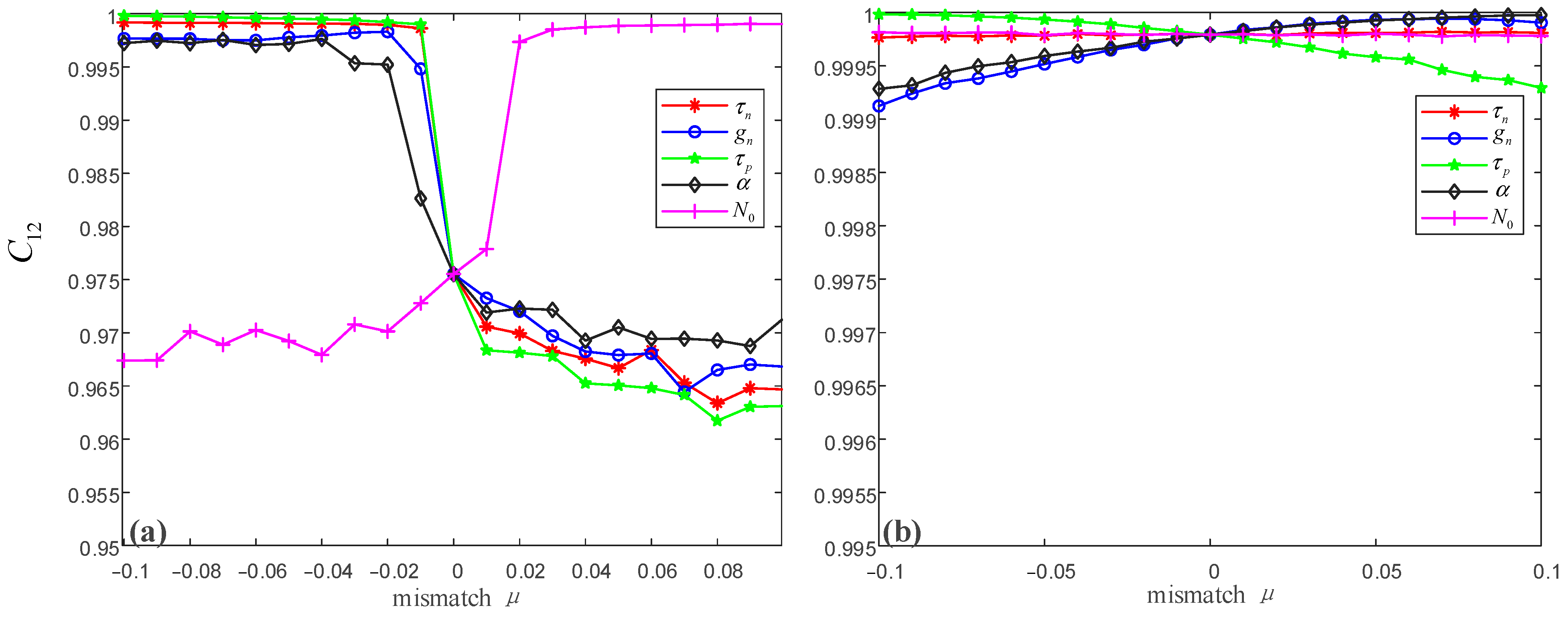
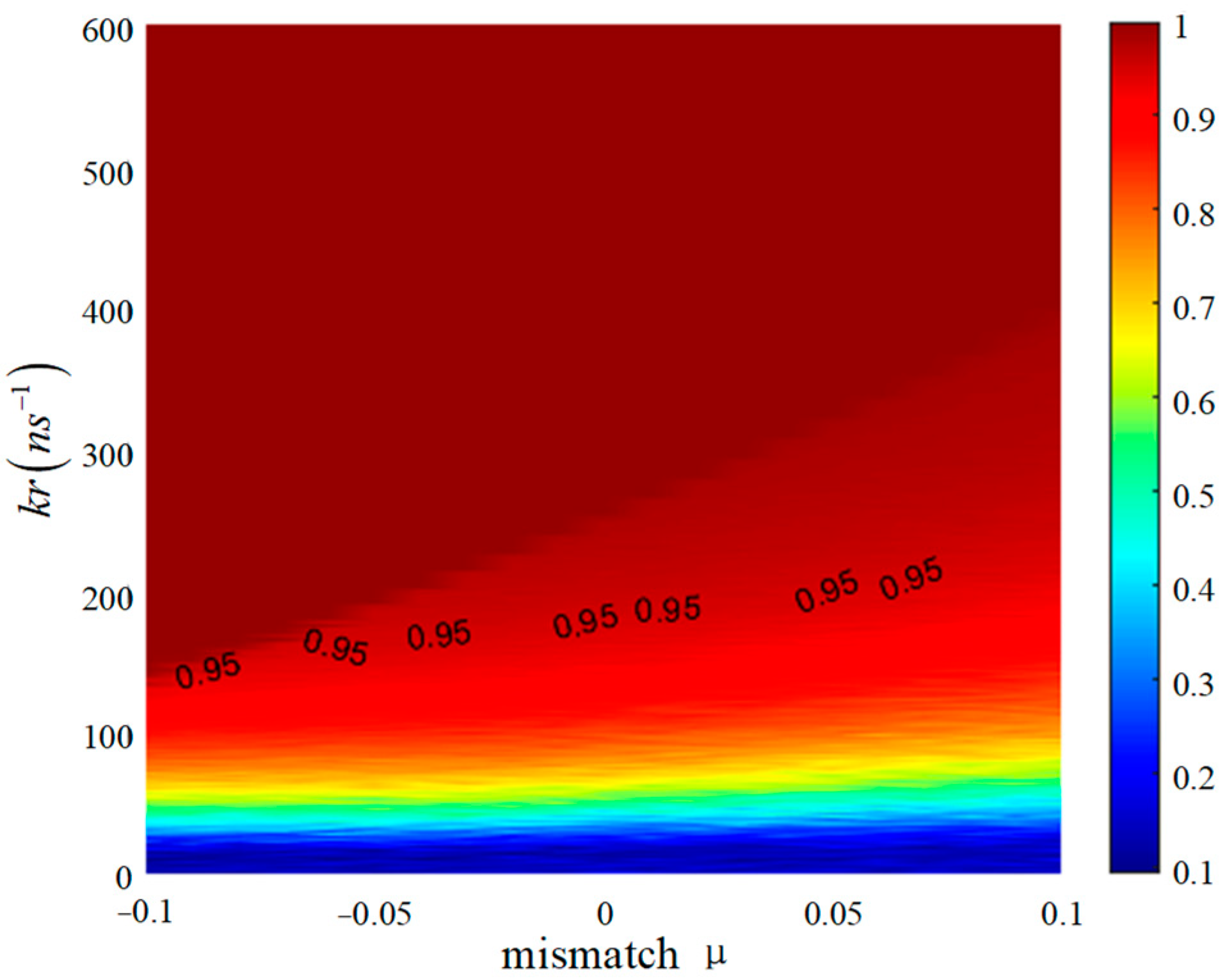
Figure 6 depicts the variation in C 12 with μ at different injection strengths. It can be observed from Figure 6 that the impact of each parameter is different. At moderate kr ( k r = 250   n s 1 ), C 12 increases with the introduction of μ, as shown in Figure 6a. The results presented here indicates a strong robustness of chaotic synchronization to internal parameter mismatch in the system, which is conducive to enhancing communication security. When kr is very large, it can be seen from Figure 6b that the value of C 12 remains consistently high across the entire range of μ; i.e., the effect of μ on the chaotic synchronization is very small. From a physical perspective, both NL1 and NL2 are subject to injection locking. Figure 7 further presents a two-dimensional colormap of C 12 with simultaneous variations in μ and kr, where the horizontal axis represents the parameter mismatch ratio, and the vertical axis stands for the injection strength with Δ f = 25 GHz. As can be seen from Figure 7, C 12 is greater than 0.95 throughout the entire plane when k r > 150 n s 1 . However, at moderate injection strength levels and μ in the range (−0.1, 0), C 12 significantly increases, and the synchronization is better. This result is consistent with Figure 6, which further verifies that the system is robust to parameter mismatch; that is, the impact of parameter mismatch on synchronization is not significant.
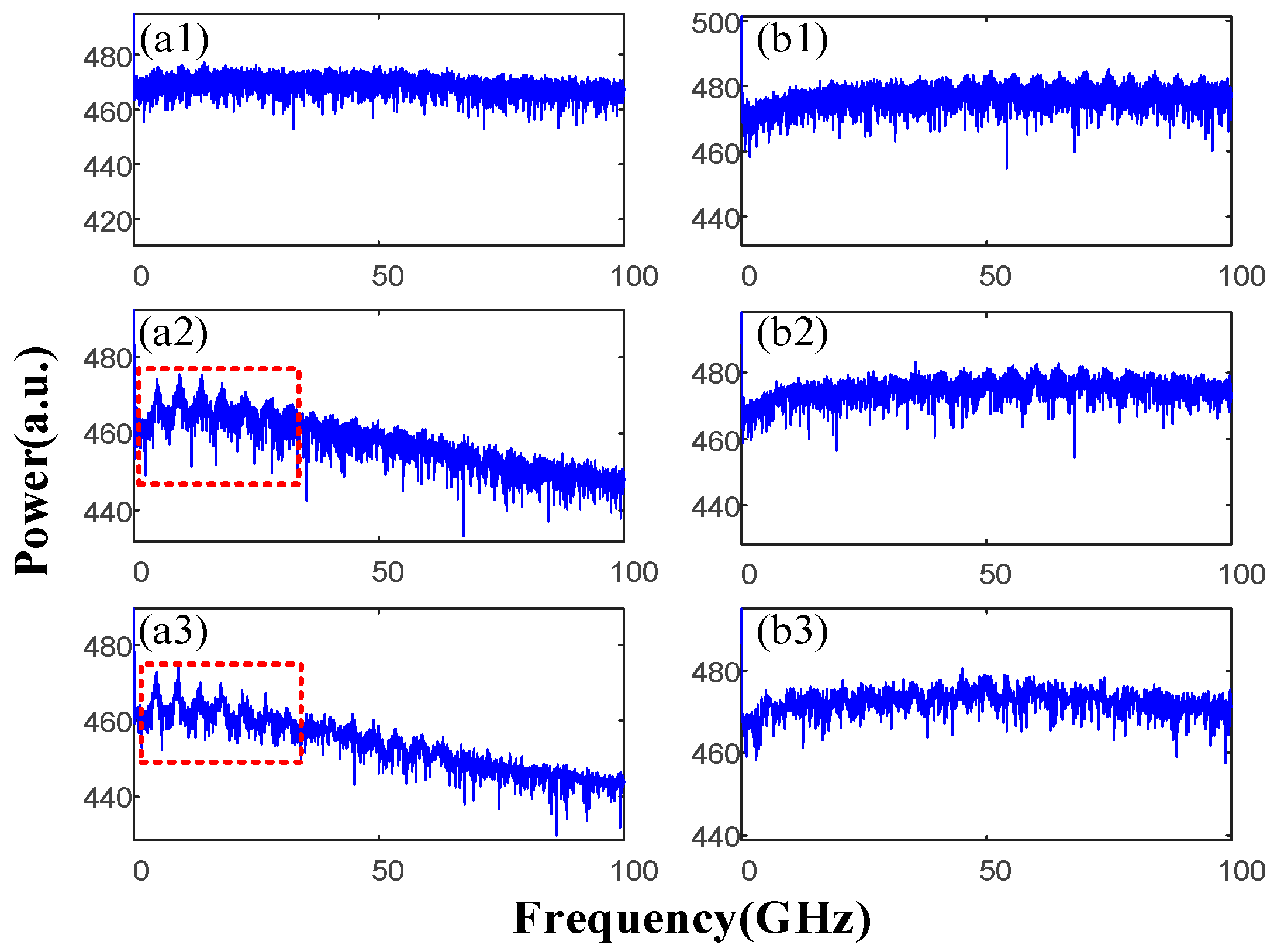
It is meaningful to evaluate the achievable transmission bandwidth of the proposed scheme before proceeding with message encoding and decoding. Since the outputs of NL1 and NL2 are almost identical, it is sufficient to study the bandwidth of NL1 here. Figure 8 displays the spectra for different values of F, β, and two injection currents I. From these spectra, it can be seen that the bandwidths for the (F, β) values (14, 0.05), (14, 0.1), and (30, 0.1) are 50.9, 7.1, and 2.5, respectively. In comparison, under the same (F, β) settings, for higher threshold I = 4Ith, the bandwidths are 65.7, 32.1, and 16.1, respectively. These results indicate that a chaotic bandwidth can be achieved in all considered scenarios, which means that NL1 and NL2 can achieve high-speed message transmission. However, when I = 2Ith, noticeable frequency spacings can be observed in the spectra for F = 14, β = 0.1, and F = 30, β = 0.1, as shown in Figure 8(a2,a3). This implies potential information leakage, which is closely related to TDS. Therefore, the selected values of F = 14, β = 0.05, and I = 2Ith in our study, as exhibited in Figure 8(a1), are more suitable.
Finally, we focus on the encoding and decoding process of bidirectional messages. In this system, NL1 and NL2 denote the communication pair (NL1 and NL2 can function as both the transmitter and the receiver), and we assume that NL1 and NL2 operate at the operating point shown in Figure 1, where the TDS of the chaotic carrier is very low, and the bandwidth is large (as in Figure 8(a1)). At the transmitter, the message is modulated onto the chaotic carrier via chaotic modulation (CM), expressed mathematically as [17,47]: I 1 m , 2 m t = I 1 , 2 t 1 + h m 1 , 2 t , where I m t is the modulated carrier transmitted over the public channel, m(t) stands for the original message, and h represents the modulation depth. At the receiver, the received modulated chaotic carrier is subtracted from the local chaotic carrier, and the resulting difference signal is passed through an LPF to recover the message.
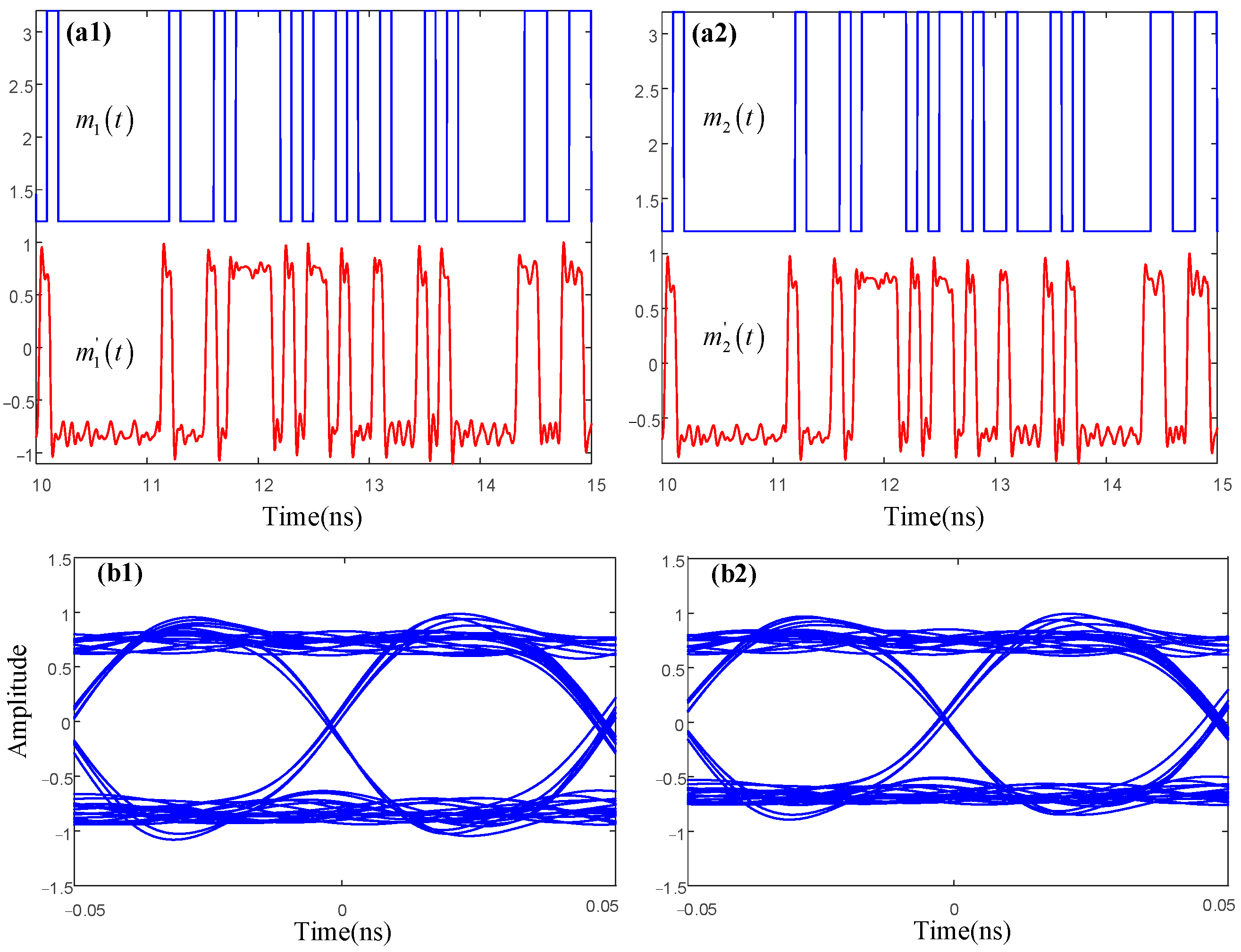
Figure 9, Figure 10 and Figure 11 illustrate the results of the message encryption and decryption processes in bidirectional communication. For observation and illustration purposes, we shift the original message upward by 3.1 (depicted in blue in Figure 9(a1,a2), Figure 10(a1,a2), and Figure 11(a1,a2)). In this paper, the performance of the chaotic communication system is measured using the Q-factor and eye diagram. This is because calculating the Q-factor is one of the most effective methods to directly reflect the system’s bit-error rate (BER) without requiring the extensive computational load involved in calculating the BER. The mathematical expression for the Q-factor is [5]: Q = I 1 I 0 / σ 1 + σ 0 , where I 1 and I 0 are the average powers of bit “1” and bit “0” in the demodulated message, respectively, and σ 1 and σ 0 are their corresponding standard deviations. It is underlined that, when Q > 6, the communication performance of the system is considered acceptable. Firstly, when the kr is moderate and there is no parameter mismatch, the bidirectional message transmission process is simultaneously explored in the results shown in Figure 9. The blue indicates the original message at the transmitter, and the red represents the corresponding recovered message at the receiver. It can be observed that NL1 and NL2 can recover the message, and the Q during decryption reaches approximately 8.7, which indicates that NL1 and NL2 can achieve bidirectional synchronous communication, and the communication performance of the two NLs is similar. Next, we further consider the parameter mismatch of NL2 [47], i.e., τ n N L 2 = 1 + μ τ n N L 1 , τ p N L 2 = 1 μ τ p N L 1 , g n N L 2 = 1 μ g n N L 1 , N 0 N L 2 = 1 + μ N 0 N L 1 , α N L 2 = 1 μ α N L 1 . Figure 10 depicts the process of bidirectional synchronous communication at k r 1 = k r 2 = 250   n s 1 and μ= −0.05, from which it is apparent that the eye diagram has widened and Q has increased to 9.5, indicating complete message recovery. Finally, increasing kr to 500   n s 1 , μ is still equal to −0.05; the results are shown in Figure 11. The message can still be completely recovered, with Q = 9.7. It is worth noting that the increase in kr enhances the quality of synchronous communication but may compromise the security of the system. The conclusions from this section are consistent with the results in Figure 6 and Figure 7, which further demonstrate the system’s strong robustness to parameter mismatch, where parameter mismatch can enhance synchronous communication performance.

4. Conclusions

In this paper, we systematically and numerically investigate the system of two mutually coupled NLs under the influence of optical feedback. The Lang–Kobayashi equations are employed for modeling, and the impact of internal parameter mismatches and injection parameters on chaotic synchronization and communication is discussed. Our research results demonstrate that the system can simultaneously meet the requirements of large bandwidth and low TDS during chaotic synchronization. Based on this, in terms of chaos synchronization performance and bidirectional message transmission, some large parameter mismatches can still maintain high-quality synchronization and communication performance, which indicates the system’s strong robustness. These findings confirm the feasibility of the proposed scheme. Therefore, this study has significance for guiding and achieving higher security in chaotic secure communication using novel NLs in future research.

Author Contributions

Methodology, X.Z. and P.M.; validation, G.G. and P.H.; investigation, X.L. and P.M.; writing—original draft preparation, X.Z., G.G. and P.H.; writing—review and editing, X.Z., X.L., P.M. and P.H. All authors have read and agreed to the published version of the manuscript.

Funding

This work was supported by the Natural Science Foundation of Shandong Province (Project ZR2020QF090), The Key Lab of Modern Optical Technologies of the Education Ministry of China, Soochow University (KJS2066); and The Key Lab of Advanced Optical Manufacturing Technologies of Jiangsu Province, Soochow University (KJS2045).

Data Availability Statement

Data is contained within the article.

Acknowledgments

The authors would like to thank all reviewers for their helpful comments and suggestions regarding this paper.

Conflicts of Interest

Author Gang Guo and Xintian Liu was employed by the company FISEC Infomation Technology Company Limited. The remaining authors declare that the research was conducted in the absence of any commercial or financial relationships that could be construed as a potential conflict of interest.

References

  1. Wang, D.; Wang, L.; Li, P.; Zhao, T.; Jia, Z.; Gao, Z.; Guo, Y.; Wang, Y.; Wang, A. Bias Current of Semiconductor Laser: An Unsafe Key for Secure Chaos Communication. Photonics 2019, 6, 59. [Google Scholar] [CrossRef]
  2. Tang, Y.; Li, Q.; Dong, W.; Hu, M.; Zeng, R. Optical Chaotic Communication Using Correlation Demodulation between Two Synchronized Chaos Lasers. Opt. Commun. 2021, 498, 127232. [Google Scholar] [CrossRef]
  3. Jiang, N.; Xue, C.; Lv, Y.; Qiu, K. Physically Enhanced Secure Wavelength Division Multiplexing Chaos Communication Using Multimode Semiconductor Lasers. Nonlinear Dyn. 2016, 86, 1937–1949. [Google Scholar] [CrossRef]
  4. Li, N.; Susanto, H.; Cemlyn, B.; Henning, I.D.; Adams, M.J. Secure Communication Systems Based on Chaos in Optically Pumped Spin-VCSELs. Opt. Lett. 2017, 42, 3494–3497. [Google Scholar] [CrossRef] [PubMed]
  5. Li, N.; Pan, W.; Yan, L.; Luo, B.; Zou, X.; Xiang, S. Enhanced Two-Channel Optical Chaotic Communication Using Isochronous Synchronization. IEEE J. Sel. Top. Quantum Electron. 2013, 19, 0600109. [Google Scholar] [CrossRef]
  6. Lin, F.-Y.; Liu, J.-M. Chaotic Lidar. IEEE J. Sel. Top. Quantum Electron. 2004, 10, 991–997. [Google Scholar] [CrossRef]
  7. Lin, F.-Y.; Liu, J.-M. Chaotic Radar Using Nonlinear Laser Dynamics. IEEE J. Quantum Electron. 2004, 40, 815–820. [Google Scholar] [CrossRef]
  8. Robertson, J.; Wade, E.; Kopp, Y.; Bueno, J.; Hurtado, A. Toward Neuromorphic Photonic Networks of Ultrafast Spiking Laser Neurons. IEEE J. Sel. Top. Quantum Electron. 2020, 26, 7700715. [Google Scholar] [CrossRef]
  9. Xiang, S.; Wen, A.; Pan, W. Emulation of Spiking Response and Spiking Frequency Property in VCSEL-Based Photonic Neuron. IEEE Photonics J. 2016, 8, 1504109. [Google Scholar] [CrossRef]
  10. Rontani, D.; Choi, D.; Chang, C.-Y.; Locquet, A.; Citrin, D.S. Compressive Sensing with Optical Chaos. Sci. Rep. 2016, 6, 35206. [Google Scholar] [CrossRef]
  11. Larger, L.; Soriano, M.C.; Brunner, D.; Appeltant, L.; Gutierrez, J.M.; Pesquera, L.; Mirasso, C.R.; Fischer, I. Photonic Information Processing beyond Turing: An Optoelectronic Implementation of Reservoir Computing. Opt. Express 2012, 20, 3241–3249. [Google Scholar] [CrossRef]
  12. Xiang, S.; Wang, B.; Wang, Y.; Han, Y.; Wen, A.; Hao, Y. 2.24-Tb/s Physical Random Bit Generation with Minimal Post-Processing Based on Chaotic Semiconductor Lasers Network. J. Light. Technol. 2019, 37, 3987–3993. [Google Scholar] [CrossRef]
  13. Zhang, S.; Tang, X.; Xia, G.-Q.; Wu, Z.-M. Fast Physical Random Bit Generation Based on an Optoelectronic Delay Loop Pumped by a Semiconductor Laser under a Modulated Optical Feedback. In Proceedings of the Semiconductor Lasers and Applications X, Online, 11–16 October 2020; SPIE: Bellingham, WA, USA, 2020; Volume 11545, pp. 70–76. [Google Scholar]
  14. Peng-Hua, M.; Wei, P.; Nian-Qiang, L.; Lian-Shan, Y.; Bin, L.; Xi-Hua, Z.; Ming-Feng, X. Performance of chaos synchronization and security in dual-chaotic optical multiplexing system. Acta Phys. Sin. 2015, 64, 124206. [Google Scholar] [CrossRef]
  15. Argyris, A.; Syvridis, D.; Larger, L.; Annovazzi-Lodi, V.; Colet, P.; Fischer, I.; García-Ojalvo, J.; Mirasso, C.R.; Pesquera, L.; Shore, K.A. Chaos-Based Communications at High Bit Rates Using Commercial Fibre-Optic Links. Nature 2005, 438, 343–346. [Google Scholar] [CrossRef] [PubMed]
  16. Pisarchik, A.N.; Ruiz-Oliveras, F.R. Optical Chaotic Communication Using Generalized and Complete Synchronization. IEEE J. Quantum Electron. 2010, 46, 279–284. [Google Scholar] [CrossRef]
  17. Jiang, P.; Zhou, P.; Li, N.; Mu, P.; Li, X. Optically Injected Nanolasers for Time-Delay Signature Suppression and Communications. Opt. Express 2020, 28, 26421–26435. [Google Scholar] [CrossRef] [PubMed]
  18. Klein, E.; Gross, N.; Kopelowitz, E.; Rosenbluh, M.; Khaykovich, L.; Kinzel, W.; Kanter, I. Public-Channel Cryptography Based on Mutual Chaos Pass Filters. Phys. Rev. E 2006, 74, 046201. [Google Scholar] [CrossRef]
  19. Porte, X.; Soriano, M.C.; Brunner, D.; Fischer, I. Bidirectional Private Key Exchange Using Delay-Coupled Semiconductor Lasers. Opt. Lett. 2016, 41, 2871–2874. [Google Scholar] [CrossRef]
  20. Cheng, M.; Luo, C.; Jiang, X.; Deng, L.; Zhang, M.; Ke, C.; Fu, S.; Tang, M.; Shum, P.; Liu, D. An Electrooptic Chaotic System Based on a Hybrid Feedback Loop. J. Light. Technol. 2018, 36, 4259–4266. [Google Scholar] [CrossRef]
  21. Chiang, M.C.; Chen, H.-F.; Liu, J.-M. Experimental Synchronization of Mutually Coupled Semiconductor Lasers with Optoelectronic Feedback. IEEE J. Quantum Electron. 2005, 41, 1333–1340. [Google Scholar] [CrossRef]
  22. Vicente, R.; Mirasso, C.R.; Fischer, I. Simultaneous Bidirectional Message Transmission in a Chaos-Based Communication Scheme. Opt. Lett. 2007, 32, 403–405. [Google Scholar] [CrossRef] [PubMed]
  23. Zhang, W.L.; Pan, W.; Luo, B.; Zou, X.H.; Wang, M.Y.; Zhou, Z. Chaos Synchronization Communication Using Extremely Unsymmetrical Bidirectional Injections. Opt. Lett. 2008, 33, 237–239. [Google Scholar] [CrossRef] [PubMed]
  24. Jiang, N.; Pan, W.; Luo, B.; Yan, L.; Xiang, S.; Yang, L.; Zheng, D.; Li, N. Properties of Leader-Laggard Chaos Synchronization in Mutually Coupled External-Cavity Semiconductor Lasers. Phys. Rev. E 2010, 81, 066217. [Google Scholar] [CrossRef] [PubMed]
  25. Jiang, N.; Pan, W.; Yan, L.; Luo, B.; Zou, X.; Xiang, S.; Yang, L.; Zheng, D. Multiaccess Optical Chaos Communication Using Mutually Coupled Semiconductor Lasers Subjected to Identical External Injections. IEEE Photonics Technol. Lett. 2010, 22, 676–678. [Google Scholar] [CrossRef]
  26. Jiang, N.; Pan, W.; Yan, L.; Luo, B.; Xiang, S.; Yang, L.; Zheng, D. Isochronal Chaos Synchronization of Semiconductor Lasers with Multiple Time-Delayed Couplings. J. Opt. Soc. Am. B 2011, 28, 1139–1145. [Google Scholar] [CrossRef]
  27. Zhang, L.; Pan, W.; Yan, L.; Luo, B.; Zou, X.; Li, S. Strong Cluster Synchronization in Complex Semiconductor Laser Networks with Time Delay Signature Suppression. Opt. Express 2022, 30, 30727–30738. [Google Scholar] [CrossRef] [PubMed]
  28. Mihana, T.; Fujii, K.; Kanno, K.; Naruse, M.; Uchida, A. Laser Network Decision Making by Lag Synchronization of Chaos in a Ring Configuration. Opt. Express 2020, 28, 40112–40130. [Google Scholar] [CrossRef]
  29. Liu, S.; Jiang, N.; Zhao, A.; Zhang, Y.; Qiu, K. Secure Optical Communication Based on Cluster Chaos Synchronization in Semiconductor Lasers Network. IEEE Access 2020, 8, 11872–11879. [Google Scholar] [CrossRef]
  30. Ohtsubo, J.; Ozawa, R.; Nanbu, M. Synchrony of Small Nonlinear Networks in Chaotic Semiconductor Lasers. Jpn. J. Appl. Phys. 2015, 54, 072702. [Google Scholar] [CrossRef]
  31. Liu, S.; Jiang, N.; Zhang, Y.; Wang, C.; Zhao, A.; Qiu, K.; Zhang, Q. Secure Key Distribution Based on Hybrid Chaos Synchronization between Semiconductor Lasers Subject to Dual Injections. Opt. Express 2022, 30, 32366–32380. [Google Scholar] [CrossRef]
  32. Elsonbaty, A.; Hegazy, S.F.; Obayya, S.S. Simultaneous Concealment of Time Delay Signature in Chaotic Nanolaser with Hybrid Feedback. Opt. Lasers Eng. 2018, 107, 342–351. [Google Scholar] [CrossRef]
  33. Rontani, D.; Locquet, A.; Sciamanna, M.; Citrin, D.S.; Ortin, S. Time-Delay Identification in a Chaotic Semiconductor Laser with Optical Feedback: A Dynamical Point of View. IEEE J. Quantum Electron. 2009, 45, 879–1891. [Google Scholar] [CrossRef]
  34. Soriano, M.C.; Zunino, L.; Rosso, O.A.; Fischer, I.; Mirasso, C.R. Time Scales of a Chaotic Semiconductor Laser with Optical Feedback Under the Lens of a Permutation Information Analysis. IEEE J. Quantum Electron. 2011, 47, 252–261. [Google Scholar] [CrossRef]
  35. Nguimdo, R.M.; Colet, P.; Larger, L.; Pesquera, L. Digital Key for Chaos Communication Performing Time Delay Concealment. Phys. Rev. Lett. 2011, 107, 034103. [Google Scholar] [CrossRef] [PubMed]
  36. Zhong, Z.-Q.; Wu, Z.-M.; Xia, G.-Q. Experimental Investigation on the Time-Delay Signature of Chaotic Output from a 1550 Nm VCSEL Subject to FBG Feedback. Photon. Res. 2017, 5, 6–10. [Google Scholar] [CrossRef]
  37. Priyadarshi, S.; Hong, Y.; Pierce, I.; Shore, K.A. Experimental Investigations of Time-Delay Signature Concealment in Chaotic External Cavity VCSELs Subject to Variable Optical Polarization Angle of Feedback. IEEE J. Sel. Top. Quantum Electron. 2013, 19, 1700707. [Google Scholar] [CrossRef]
  38. Li, N.; Pan, W.; Locquet, A.; Citrin, D.S. Time-Delay Concealment and Complexity Enhancement of an External-Cavity Laser through Optical Injection. Opt. Lett. 2015, 40, 4416–4419. [Google Scholar] [CrossRef]
  39. Li, N.; Pan, W.; Xiang, S.; Yan, L.; Luo, B.; Zou, X.; Zhang, L.; Mu, P. Photonic Generation of Wideband Time-Delay-Signature-Eliminated Chaotic Signals Utilizing an Optically Injected Semiconductor Laser. IEEE J. Quantum Electron. 2012, 48, 1339–1345. [Google Scholar] [CrossRef]
  40. Hong, Y. Experimental Study of Time-Delay Signature of Chaos in Mutually Coupled Vertical-Cavity Surface-Emitting Lasers Subject to Polarization Optical Injection. Opt. Express 2013, 21, 17894–17903. [Google Scholar] [CrossRef]
  41. Wu, J.-G.; Wu, Z.-M.; Xia, G.-Q.; Feng, G.-Y. Evolution of Time Delay Signature of Chaos Generated in a Mutually Delay-Coupled Semiconductor Lasers System. Opt. Express 2012, 20, 1741–1753. [Google Scholar] [CrossRef]
  42. Mu, P.; Pan, W.; Yan, L.; Luo, B.; Li, N.; Xu, M. Experimental Evidence of Time-Delay Concealment in a DFB Laser With Dual-Chaotic Optical Injections. IEEE Photonics Technol. Lett. 2016, 28, 131–134. [Google Scholar] [CrossRef]
  43. Hong, Y.; Quirce, A.; Wang, B.; Ji, S.; Panajotov, K.; Spencer, P.S. Concealment of Chaos Time-Delay Signature in Three-Cascaded Vertical-Cavity Surface-Emitting Lasers. IEEE J. Quantum Electron. 2016, 52, 2400508. [Google Scholar] [CrossRef]
  44. Zhang, X.; Guo, G.; Liu, X.; Hu, G.; Wang, K.; Mu, P. Dynamics and Concealment of Time-Delay Signature in Mutually Coupled Nano-Laser Chaotic Systems. Photonics 2023, 10, 1196. [Google Scholar] [CrossRef]
  45. Wu, S.; Buckley, S.; Schaibley, J.R.; Feng, L.; Yan, J.; Mandrus, D.G.; Hatami, F.; Yao, W.; Vučković, J.; Majumdar, A.; et al. Monolayer Semiconductor Nanocavity Lasers with Ultralow Thresholds. Nature 2015, 520, 69–72. [Google Scholar] [CrossRef]
  46. Qu, Y.; Xiang, S.; Wang, Y.; Lin, L.; Wen, A.J.; Hao, Y. Concealment of Time Delay Signature of Chaotic Semiconductor Nanolasers with Double Chaotic Optical Injections. IEEE J. Quantum Electron. 2019, 55, 2000407. [Google Scholar] [CrossRef]
  47. Li, N.; Pan, W.; Yan, L.; Luo, B.; Xu, M.; Tang, Y.; Jiang, N.; Xiang, S.; Zhang, Q. Chaotic Optical Cryptographic Communication Using a Three-Semiconductor-Laser Scheme. J. Opt. Soc. Am. B 2012, 29, 101–108. [Google Scholar] [CrossRef]
Figure 1. The schematic diagram of bidirectional synchronous communication based on closed-loop mutually coupled NLs in a closed-loop system. NL1: the first nano-laser; NL2: the second nano-laser; M: mirror; FC: fiber coupler; OI: optical isolator; OC: optical circulator; EDFA: erbium-doped optical fiber amplifier; OSC: oscilloscope; LPF: low-pass filter; PD: photodetector; D: demodulator; m(t): message; m’(t): decrypted message.
Electronics 13 00239 g001
Figure 2. The time-series plots (in red), ACF (in blue), and power spectrum (in black) of the chaotic signals from NL1 and NL2. (a1c1): NL1, (a2c2): NL2.
Electronics 13 00239 g002
Figure 3. Cross-correlation function (CCF) plots of NL1 and NL2.
Electronics 13 00239 g003
Figure 4. Line plots of the variation in the cross-correlation coefficient C 12 with (a) the injection intensity and (b) the frequency detuning.
Electronics 13 00239 g004
Figure 5. The two-dimensional colormap of the cross-correlation coefficient C 12 on the k r , Δ f plane.
Electronics 13 00239 g005
Figure 6. The effect of parameter mismatch on the synchronization performance of the system at different injection strengths. Δ f = 25 GHz. (a) k r = 250   n s 1 ; (b) k r = 500   n s 1 .
Electronics 13 00239 g006
Figure 7. The two-dimensional colormap of the cross-correlation coefficient C 12 on the μ , k r plane.
Electronics 13 00239 g007
Figure 8. Spectra of NL1 at different values of F, β, and I. (a1a3): I = 2Ith, (b1b3): I = 4Ith. (a1,b1): F = 14, β = 0.05. (a2,b2): F = 14, β = 0.1. (a3,b3): F = 30, β = 0.1.
Electronics 13 00239 g008
Figure 9. The encoding and decoding process of NL1 and NL2. h = 0.8, 8 Gbit/s original message. k r 1 = k r 2 = 250   n s 1 , Δ f = 25 GHz, μ = 0. (a1,b1) NL1 decryption and eye diagram, (a2,b2) NL2 decryption and eye diagram. In the first row, blue—original message m(t), red—recovered message m’(t). The original message is shifted upward by 3.1.
Electronics 13 00239 g009
Figure 10. The encoding and decoding process of NL1 and NL2. h = 0.8, 8 Gbit/s original message. k r 1 = k r 2 = 250   n s 1 , Δ f = 25 GHz, μ = −0.05. (a1,b1) NL1 decryption and eye diagram, (a2,b2) NL2 decryption and eye diagram. In the first row, blue—original message m(t), red—recovered message m’(t). The original message is shifted upward by 3.1.
Electronics 13 00239 g010
Figure 11. The encoding and decoding process of NL1 and NL2. h = 0.8, 8 Gbit/s original message. k r 1 = k r 2 = 500   n s 1 , Δ f = 25 GHz, μ = −0.05. (a1,b1) NL1 decryption and eye diagram, (a2,b2) NL2 decryption and eye diagram. In the first row, blue—original message m(t), red—recovered message m’(t). The original message is shifted upward by 3.1.
Electronics 13 00239 g011
Table 1. Parameters employed in the numerical simulations [17].
ParameterDescriptionValue
Γ Confinement factor0.645
τ n
τ p
Carrier lifetime
Photon lifetime
1 ns
0.36 ps
tdFeedback delay0.2 ns
g n Differential gain 1.64   ×   10 6   c m 3 / s
N 0 Transparency carrier density 1.1   ×   10 18   c m 3
ε Gain saturation factor 2.3   ×   10 17   c m 3
α Linewidth enhancement factor5
V b Volume of active region 3.96   ×   10 13   c m 3
λ 0 Wavelength of NL1591 nm
R Laser facet reflectivity0.85
R e x t External facet power reflectivity0.95
R i n j Injection ratio0–0.1
nRefractive index3.4
LCavity length 1.39   μ m
QQuality factor428
fFeedback coupling fraction0–0.9
Disclaimer/Publisher’s Note: The statements, opinions and data contained in all publications are solely those of the individual author(s) and contributor(s) and not of MDPI and/or the editor(s). MDPI and/or the editor(s) disclaim responsibility for any injury to people or property resulting from any ideas, methods, instructions or products referred to in the content.