Review

A Comprehensive Review on Matrix-Integrated Single-Stage Isolated MF/HF Converters

by
Tahmin Mahmud
and
Hang Gao
*
PEMD Group, School of Engineering and Computer Science, Washington State University, Vancouver, WA 98686-9600, USA
*
Author to whom correspondence should be addressed.
Electronics 2024, 13(1), 237; https://doi.org/10.3390/electronics13010237
Submission received: 21 November 2023 / Revised: 27 December 2023 / Accepted: 28 December 2023 / Published: 4 January 2024

Abstract

:
A matrix-integrated single-stage isolated MF/HF AC-AC/DC-AC/AC-DC converter topology stands out as an innovative concept, offering a multitude of advantages including minimal output current THDs, near UPF, 4Q operation, smooth BPF capability, and increased power density leading to the converter’s enhanced efficiency, cost-effectiveness, and reliability. These characteristics render it an exemplary choice for RE-based power conversion applications. In fact, the matrix-integrated single-stage isolated MF/HF converters have witnessed an increased adoption of RE-based grid interconnection in recent years, specifically within solar PV, WECS, grid-tied offshore WF, and FC-based applications. RE sources produce variable and intermittent AC power by nature, further necessitating conversion to a stable and grid-compatible AC voltage and frequency. This is where MCs offer distinct advantages when contrasted with the conventional indirect dual-stage VSC-based rectifier–inverter topology. In this paper, a total of 22 matrix-integrated HF isolated converter topologies are broadly explored. Our study provides a comprehensive analysis and classification of matrix-integrated isolated single-stage MF/HF AC-AC converters, DC-AC inverters, and AC-DC rectifier topologies including modified topology architectures, control method, modulation techniques along with significant applications. Within this scope, the matrix-integrated converter topologies are categorized based on their architectures and other relevant subvariants. Our primary objective of this study is to impart a clear understanding of the overarching framework and principles of the matrix-integrated single-stage isolated MF/HF converter topologies and stimulate the creation of new topologies that cater to specific requirements for grid-interconnected systems.

1. Introduction

An MC is a highly versatile and advanced power electronic topology that has gained significant attention in recent years, making it an exciting topic for research and development in the field of power electronics. Unlike traditional converters, such as an AC-AC VSC or an AC-AC CSC, an MC does not have any energy-storage elements like capacitors or inductors. Instead, it directly converts energy from the input side to the output side, making it a compact bidirectional power converter. The key characteristic of an MC is its ability to control both the magnitude and frequency of the output voltage. It provides a wide range for output voltage and frequency, making it suitable for various applications, including motor drives and RE conversion systems. One of the most significant advantages of an MC is its high efficiency and reduced reliance on bulky and maintenance-intensive components, such as electrolytic capacitors. This makes it an attractive option for compact and reliable power conversion systems, which further enhances its appeal in modern power systems. The concept of the MC topology was initially introduced by M. Venturini and A. Alesina around 1981 [1]. Detailed classification of the MC topologies is discussed in references [2,3,4]. Over time, MCs underwent significant innovations to establish themselves as a unique category.
MCs are primarily categorized based on the number of power conversion stages, resulting in two main categories: (a) DMC and (b) IMC. The DMC is a single-stage AC/AC converter featuring nine bidirectional switches located between the input and output terminals. These switches establish a direct connection between input lines and output lines without the need for any intermediate storage elements. This unique configuration enables the direct synthesis of output voltage waveforms from input voltages. On the other hand, IMC is a two-stage AC-AC converter. In the rectification stage, it generates a high DC voltage while maintaining a UPF with the input. The second stage is the inversion which produces adjustable AC voltages at varying frequencies. MCs are experiencing increased adoption in grid-interconnection applications related to RE-based sources and BESS. This trend has been documented in the existing literature as (a) a Sparse MC for gearless WECS in [5], (b) MC for RE-based DFIG in [6], (c) MMxCs for WPA in [7], harmonic control of MC for unregulated input solar PV voltage in [8], MMxC for high-power wind turbines in [9], MMxC for grid-interconnection in [10,11], parallel multi-MC system for intelligent micro-grid [12], hybrid DAB and MC-based topology for grid interactive PV-Battery system [13], hybrid MC for mining vehicle applications in [14], and MPC for MC-based SST for utility grid interaction in [15]. In fact, MC topologies are highly versatile and efficient, making them well-suited for grid-interconnection applications and BESS, where efficiency, power quality, bidirectional power flow, and compact design are crucial factors.
Recently, extensive research efforts have been focused on isolated AC-AC/DC-AC/AC-DC topologies that integrate MFT or HFT as a viable alternative to traditional line-frequency transformers. Furthermore, with the world striving to embrace clean and eco-friendly transportation paradigms, the requirement for high-power isolated bidirectional AC-DC converters connecting 3P AC mains to the EV battery’s DC voltage for quick EV and PHEV charging has also intensified in recent years. The conventional approach to design AC-DC converters in either the rectifier mode or inverter mode lies on the intricate interplay between topology architecture and transformer configuration. A notable instance reported in [16] involved a two-stage unidirectional FB SR AC-DC charger and a bidirectional AC-DC-DC topology for Level 1 EV charging. This two-stage circuit encounters challenges such as circuit complexity, lengthy power conversion stage, voluminous DC-Link requirement, and suboptimal power density. Addressing these challenges, numerous research endeavors showcase innovative solutions. In a recent review paper [17], an insightful analysis of single-stage HF isolated AC-DC converters is presented, with a particular focus on the location of the ES elements. While this paper itself is informative in its coverage of isolated AC-DC MC topologies, it falls short of classifying a wide range of single-stage HF isolated AC-AC converter or DC-AC inverter circuit topologies. Likewise, reference [18], diligently undertook a comprehensive classification of isolated MCs based on AC-side drive techniques. However, this review paper also does not combine different circuit structures of AC-AC converter or DC-AC inverter topologies. Similarly, Refs. [2,19] investigate DC-Link PWM AC-AC converters and DAB converters, respectively. These factors lie outside the purview of our selected classification schema. The lack of an extensive report on matrix-integrated single-stage isolated MF/HF AC-AC/DC-AC/AC-DC converter topology hinders a holistic understanding of the distinctions between the diverse system architecture, topology, control methods, and modulation techniques. Our review paper aims to address this gap, making significant contributions in the following areas:
  • Until now, no review article has successfully classified all three matrix-integrated single-stage isolated AC-AC/DC-AC/AC-DC circuit configurations within a single report, which is a gap that our work seeks to fill.
  • Our in-depth study focuses on versatile matrix-integrated single-stage isolated AC-AC/DC-AC/AC-DC topologies, providing valuable insights into its various configurations and characteristics, thereby enriching the existing knowledge in the field. Additionally, three tables have been incorporated to facilitate a detailed comparison and contrast of each topology with a focus on performance analysis as well.
  • A broad overview and summary of various control strategies, modulation schemes, and applications for the three highlighted topologies is presented in a tabulated format. The table encompasses a complete system design specifications and various features of the converter system, such as front-end and rear-end converter types, the number of semiconductor devices utilized, input–output voltage levels, and efficiency etc. These aspects can be a valuable guide for engineers or design professionals.
  • Several unique converter control methods and modulation techniques have been identified and thoroughly detailed. Additionally, key operating waveforms for some converter types have been illustrated and analyzed.
To provide a coherent framework, this paper is structured into the following sections: Section 2 introduces and analyzes diverse matrix-integrated single-stage AC-AC/DC-AC/AC-DC converter topologies encompassing their auxiliary structures and subvariants. Notably, AC-AC converter, DC-AC inverter, and AC-DC rectifier topologies are separately investigated under three different subcategories. Three comparative analysis of different matrix-integrated single-stage isolated converter topologies and their advantages/disadvantages along with their performance have been incorporated in this section. In Section 3, we have crafted a concise overview that outlines and explains the control strategies and modulation schemes pertaining to each of the three matrix-integrated isolated converter topologies. In this section, we have also incorporated two additional tables that provide a comparative analysis of different control methods and modulation schemes. Additionally, in Section 4, we conducted a focused literature review to evaluate the status of matrix-integrated single-stage isolated converter topologies in industrial/residential applications, RE-based grid-interconnection and ES system. Lastly, in Section 5, we draw a concluding remark and discuss future trends.

2. Matrix-Integrated Single-Stage Isolated MF/HF Converter Topologies

From the extensive body of literature, it becomes apparent that the matrix-integrated single-stage isolated MF/HF AC-AC/DC-AC/AC-DC converter topologies exhibit remarkable versatility in terms of power conversion stages, types of MC employed within the circuit, system network, galvanic isolation, semiconductor device variations, power-flow directions, application domains, drive techniques, and more. Ranging from LV scenarios to MV scenarios, numerous scholarly studies have extensively investigated isolated MC topologies. The complete classification of these circuits is presented in Figure 1 via a tree diagram, along with the corresponding references. Relevant figures have also been provided for clarity. Based on this figure, it becomes apparent that the majority of the matrix-integrated single-stage isolated AC-AC/DC-AC/AC-DC converter topologies can be primarily classified according to the power-conversion-phase type of the AC source or load. Furthermore, both 1P and 3P topologies are subcategorized based on whether they are DMC-based or employ other special topologies. Additionally, each of the DMC-based subvariants, which include the single converter-based topology, cascaded topology, resonant tank-based or resonant tank-less topologies, CT-HFT-based topologies, and MMxC-based topologies, are also explicitly highlighted. In the later sections, the different classes of subsequent matrix-integrated MF/HF converters are illustrated as: resonance-based converter in Figures 2 and 3, resonance-less converter in Figure 4, CT-HFT converter in Figures 5 and 6, single converter in Figures 7 and 8, cascaded converter in Figures 9 and 10, single inverter in Figures 11, 12, and 13, cascaded inverter in Figure 12, resonance-based rectifier in Figures 15 and 16, resonance-less rectifier in Figure 17, flyback-integrated rectifier in Figure 18, single-rectifier in Figures 19, 20, and 21, cascaded rectifier in Figure 22, MMxC rectifier in Figure 23, and 3P VSC-based MC-type AC-DC rectifier in Figure 24.

2.1. Matrix-Integrated Single-Stage Isolated AC-AC Converter Topology

The classification of the matrix-integrated single-stage isolated AC-AC MC topology initiates with an analysis of its power-conversion-phase type on the source or load end. Based on the power-conversion-phase type, the circuits can be classified as (a) 1P AC-1P AC converter and (b) 3P AC-3P AC converter structure, as shown in Figure 1 with blue ink. In terms of system architecture, the majority of the 1P and 3P circuits fall under the most popular DMC-based isolated AC-AC topology that does not require bulky electrolytic capacitors. Implementation of DC-link-less AC-AC MCs in various noteworthy applications are based on SST and direct 3 × 3 AC drive which have resulted in a cost-efficient circuit configuration, weight decrement, and better compactness.
The following subsection will provide an in-depth analysis of different 1P and 3P AC-AC converter topology.

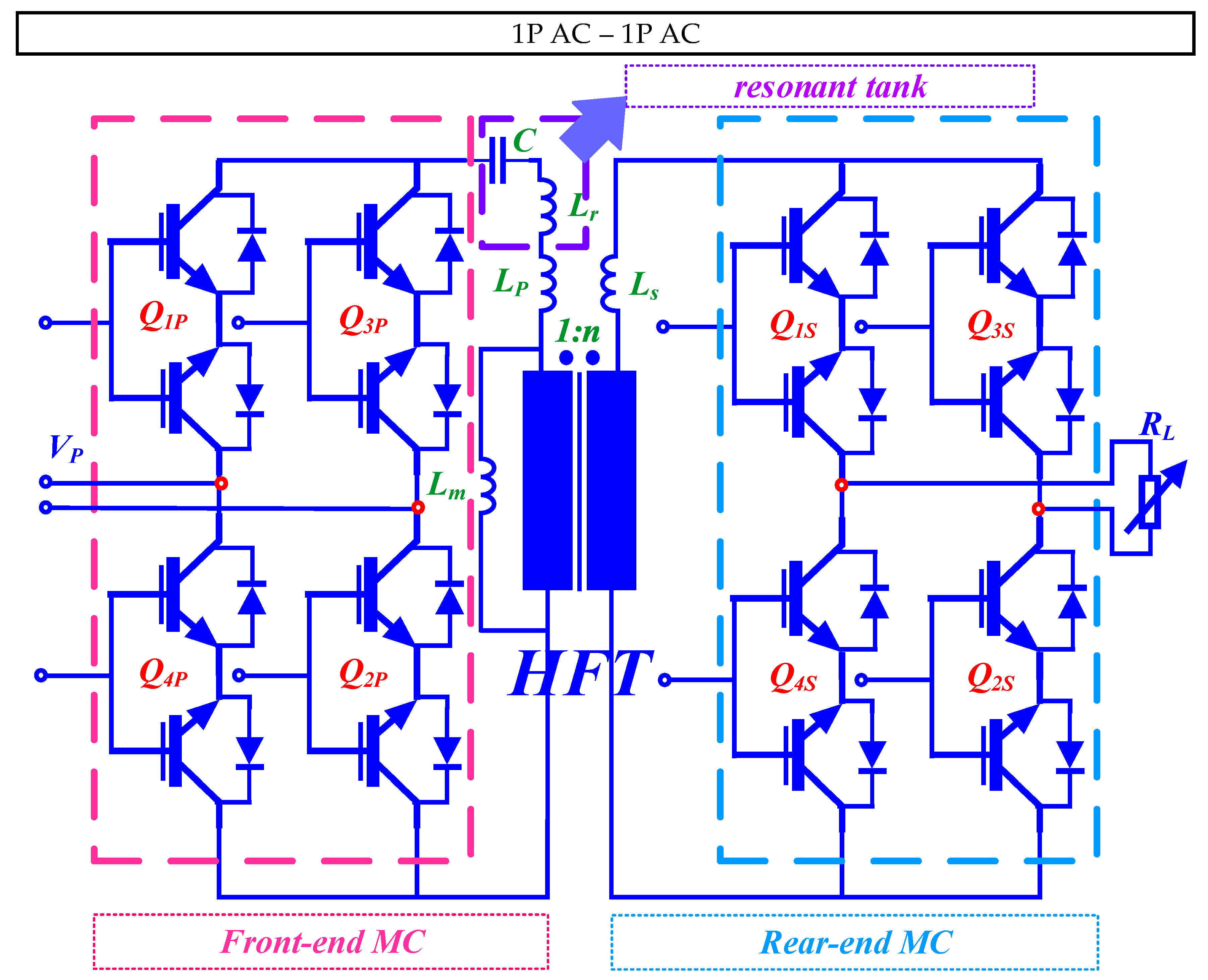
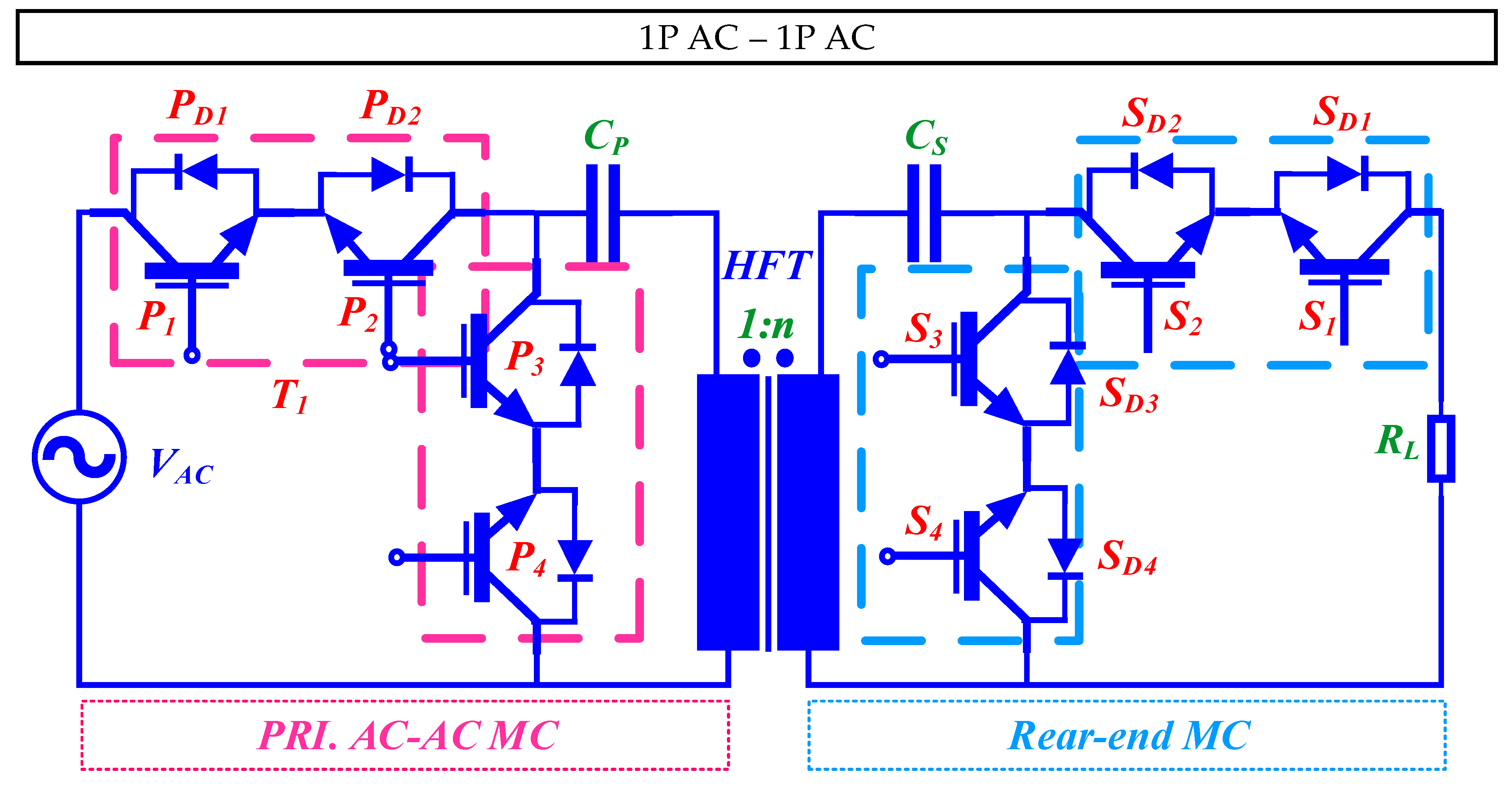
2.1.1. 1P AC-1P AC Circuit

1P AC-1P AC conversion is the most prevalent type of conversion in which both the source and load operate as 1P AC systems. Within the 1P AC-1P AC DMC-based circuit category, further subdivisions are made based on the presence or absence of a primary-side AC-link resonant tank which can be connected to the HFT in series or in parallel. In HF power conversion topologies, resonant tanks play a pivotal role in enhancing efficiency and minimizing switching losses. Specifically, in MC-based systems, where direct AC-AC conversion is achieved without the need for an intermediate DC-link, resonant tanks become crucial elements. Resonant tanks, typically implemented using inductors and capacitors, are strategically designed to resonate at the converter’s operating frequency. This resonance allows for ZVS and ZCS conditions during the switching transitions.

2.1.1.1. Resonance-Based Converter

Resonant-tank-based matrix-integrated isolated MF/HF 1P AC-1P AC MC topologies are discussed in the range of references [20,21]. The topology studied in [20] is exemplified in Figure 2. It has front-end and rear-end MC-based circuits. This topology is commonly known as direct AC-AC conversion SST. The control technique of this topology is the simplified logic-based control in order to achieve soft switching in response to load variation. The controller is designed in the energy injection/regeneration mode. The control mode is based on a quantum energy injection/absorption principle.
Two key advantages of this converter with the proposed control method are (a) ZVS, and (b) resonant current tracking for self-tuning. The authors also report using an FCS MPC-based gating generation where the algorithm optimizes the switching current vectors via a finite number of enumerations and selects the optimal gatings to be provided to the MC circuit via present- and future-state space variable prediction models utilizing the first order Euler’s forward discrete time model and minimizing the cost function. One of the common challenges of adopting an MPC algorithm for gate pulse generations is the control complexity of achieving a soft-switching scheme which further puts pressure on the additional LC resonant tank requirement. On top of that, for any MC-based SST architecture, design accuracy of the HFT is crucial for the overall performance of the power conversion. The authors in [20] provide a physics-based design-optimization algorithm for the SST’s HFT.
A similar resonant-tank-based 1P AC topology has been studied in [21]. A direct symmetrical and back-to-back front-end as well as rear-end AC-AC MC converter for EPT based on energy-injection control has been proposed in this study. The basic EPT configuration is shown in Figure 3. The primary and secondary self-inductance and compensation capacitors act as an SR tank which ensures soft switching of the primary and secondary MC circuits. The researchers face a crucial decision-making process, carefully weighing the advantages of a complex circuit structure featuring additional switches against the inherent drawbacks associated with conventional transformers, e.g., (a) DC bias, (b) no-load losses, and (c) magnetic saturation. However, this innovative topology successfully achieves HF current generation, showcasing its remarkable potential in HF power conversion applications. This topology further promises a stable output current with variable load response.
The subsequent key operating waveforms of this converter are shown in the inset of Figure 3a,b. The left inset shows the key operating waveform of the front-end converter, while the right inset exhibits the key operating waveform of the rear-end converter.

2.1.1.2. Resonance-Less Converter

Numerous studies have delved into resonant-tank-less 1P AC-1P AC converter topologies. The proposed structure in [22] reflects a similar configuration as demonstrated in Figure 4. It comes up with a novel commutation technique derived from the 4-step commutation which has resolved synchronization challenges between the commutation timing and the leakage inductance as well as reducing switching losses. The topology has bidirectional MC-based circuits both at the front end and rear end. The front-end MC circuit is fed with a voltage source, while the output is a current source. The MC-based circuits in both sides use a leakage-inductance-tolerant commutation strategy and also achieves ZCS for safe soft-switching ability.
This topology finds a counterpart in the Dual-CBM configuration, as detailed in [23]. The Dual-CBM topology is prominent in microgrid clusters and generation systems, which has led to its recognition as MMPC. Specifically, the 1P variant of the Dual-CBM topology employs LF input voltage modulation to generate an MF or HF voltage waveform.
The 1P solution of the converter has a front-end and rear-end b2b cycloconverter-based module. However, the 1P topology faces limitations when it comes to interconnecting two drives and frequency-regulation compatibility. Consequently, a multi-input 3 × 1 AC-AC topology utilizing the Dual-CBM structure has been proposed to overcome these limitations. The 1P topology can be transformed into a modular structure derived from the topology shown in Figure 4. This modification allows for 3P input, offering three input options simultaneously. It also maintains characteristics such as modularity, galvanic isolation, and bidirectional power capability. It becomes possible to generate non-integral multiples of the input frequency. For instance, the system can produce a 40 Hz output voltage from a 50 Hz input voltage. Moreover, this new configuration exhibits exceptional output grid frequency regulation, even when subjected to a substantial variation in input grid frequency. Furthermore, the capabilities of this 3 × 1 AC-AC isolated converter system can be extended to create a 3 × 3 MC topology. It is worth noting that the input and output voltage and current characteristics of the 3 × 3 MC topology closely resemble those of classical MCs. This innovative converter topology represents a notable advancement in the realm of grid-interconnection applications. It leverages bidirectional switch-based converters and offers increased versatility and adaptability.
The effective key operating waveform for two different commutation methods have been incorporated in Figure 4a,b. The 4-step commutation method illustrated in Figure 4a demonstrates that the initial commutation occurs in the output bridge, and the transition from state three to state four instigates the activation of the protection clamp. Consequently, the output voltage Vo is sustained at a level equivalent to the negative clamp voltage, until the reversal of IL is driven by the combined voltage VT + Vo. This results in power dissipation within the clamp. In contrast, the proposed commutation method, as depicted in Figure 4b, achieves the reversal of IL without triggering the clamp, owing to the incorporation of the proposed current-decoupling phase.

2.1.2. 3P AC-3P AC Circuit

Unlike the 1P topologies, the 3P AC-3P AC conversion involves systems where both the source and load operate as 3P AC systems. Within the 3P AC-3P AC DMC-based circuit category, additional variants in our study include CT-HFT converter topologies, along with single and cascaded converter types.

2.1.2.1. CT-HFT Converter

Several studies have provided insights into CT-HFT-based topologies which will be discussed in detail in the later sections. Figure 5 and Figure 6 illustrate the Type-I and Type-II MC-based SST architectures, integrating CT-HFT as an AC-link. There are three primary types of MC-based SST architectures, specifically crafted for distribution and transmission feeders. Further discussions on Type-III are reflected in the subsequent sections.
Type-I SST utilizes a bank of three HFTs. The topology presented in [24] features bidirectional complimentary IGBTs (S1 and S2), PP structured HFTs and two diode bridges, offering soft-switching and grid-side converter functionality. The load side of the Type-I SST is a typical MC circuit. The LF AC to HF AC power conversion does not require bulky electrolytic capacitors. HF AC directly feeds towards the rear-end MC circuit. This topology achieves bidirectional power flow via the rear-end MC circuit. Type-II architecture incorporates a cascaded FBC connected to the secondary side of the HFTs, distinguishing it from Type-I where the MC is connected to the secondary side. A bidirectional MC circuit is located at the primary side of the converter topology. Additionally, the HFT which has been incorporated into this architecture has a push–pull configuration. The front-end MC of the Type-II architecture adopts a PWM (50% duty cycle modulation) technique, which suppresses the switching commutation losses coming from the leakage inductor as well as CMV. However, a major drawback of this topology is the increased switch counts.
In the work outlined in [25], another isolated 3 × 3 PET-based AC-AC MC converter architecture is proposed. The PET-based topology of this converter incorporates a CT-HFT similar to the Type-II SST architecture. The primary-side converter has a leakage commutation frequency minimization capability. The modulation method employed in this converter is the improved CSVPWM. The AC-side connection has seen a three-wire nature, employing bidirectional semiconductor devices which have a different configuration derived from the conventional MC-based circuit. The three-wire nature of the converter circuit reduces shoot-through switching commutations. Additionally, source-based commutation of leakage energy is adopted in this topology. However, this converter has some major drawbacks: (a) high semiconductor device count, (b) high conduction loss, (c) high switching power loss, (d) heat dissipation of the semiconductor devices, (e) complex control and computational burden, and (f) limited ride-through capability. This configuration encompasses nearly all the advanced attributes of PWM AC drives and holds significant promise as a compact solution for isolated motor drives.

2.1.2.2. Single Converter

Single converters in the context of 3P AC-3P AC conversion refer to those which operate independently, distinct from cascaded modular structures or parallel converter configurations. The Type-III SST architecture as shown in Figure 7 is a prime example of single-converter topology which employs two winding transformers to mitigate excess copper demand, but it lacks the CMV capability like Type-II SST architecture. The lowercase a, b, c indicates the grid-side front-end 3P lines whereas the uppercase A, B, C indicates load-end 3P lines. In addition to this, the Type-III SST architecture reported in [24] employs b2b front-end and rear-end indirect MC circuits with a virtual DC-link. In [24], the authors have proposed a novel AC-AC converter structure based on Type-III, but it requires hard switching for the primary-side converter.
The key operation of this converter is achieved using two signals, S and C, as depicted in Figure 7. Flux balance is maintained over a complete cycle of signal S within a 2Ts timeframe. Signal C is associated with the commutation of leakage energy and will be elaborated upon in the subsequent section. The grid-side converter is modulated to rectify the input of three-phase voltage into a virtual DC, subsequently inverting the rectified DC into a high-frequency AC over one period of signal S.
Other classifications of SSTs provided in [22] are (a) direct and (b) hybrid voltage source DAB with rear-end MC-based topology. The direct SST topology is similar to the Type-III SST architecture where front-end and rear-end converters are both bidirectional MC-based circuit. With no intermediary DC-link energy-storage elements, the direct SST topology ensures a smaller footprint.
In another instance of a single converter for single-stage 3 × 3 AC-AC conversion, documented in [26], the configuration involves 4Q switches and an optional HFT, resembling the topology depicted in Figure 7. Some of the advantages of this topology are: (a) a voltage step-up mode and (b) variable output voltage magnitude and frequency. The topology has b2b MC-based circuits in both sides of the galvanic HFT. The converter is well-fitted with switching techniques like SPWM or SVPWM. This converter topology shows a semi-soft-switching technique. The front-end converter employs a modulation scheme with a control objective of suppressing the AC-link ripples experienced in the voltage waveform’s envelope in each phase. The rear-end converter employs an improved SVPWM modulation scheme using two techniques: (a) utilization of a conventional SVM scheme during the positive half cycle of the Ts and (b) utilization of SVM scheme with the consideration of a negative DC bus voltage during the negative half-voltage propagation. As compared to similar dual b2b MC topologies, this converter topology has successfully resolved the control challenges of the secondary-side MC-based circuit. While the conventional modulation technique of the secondary-side MC lacks the mitigation of high voltage stress d v d t of the semiconductor devices as well as unexpected voltage ripples in the HFT AC-link voltage waveform envelope, the proposed converter in [26] resolves this using a fine switching technique. The secondary-side modulation scheme can also support other converter control strategies, e.g., v/f control and vector control techniques. Experimental results prove that this MC topology achieves lower EMI and THD in the unfiltered output voltage waveform. This converter is well suited for AC drive applications with specific demands for HV AC voltages and the necessity of electrical isolation from the input 3P power source.
Reference [27] presents a parallel resonant AC-AC converter topology. This configuration is similar to the topology illustrated in Figure 7 from input AC towards output AC which includes an input LC current ripple-suppression filter followed by a 3 × 1 MC circuit topology, AC-link capacitor C1, RL series-resonant tank, and AC HFT galvanic isolation. At this point, everything is symmetrical to the input side on the secondary side of the AC HFT link. The converter incorporates two AC-link capacitors (C1 and C2) to facilitate soft-switching commutation. To maintain smooth converter operation, AC-link capacitors are positioned on either side of the transformer. These capacitors serve a dual purpose by providing pathways for the currents of the primary and secondary leakage inductances when the input and output switches are turned off, thus averting voltage spikes. In addition to this, the converter incorporates small low-pass filters at both the input and load terminals to effectively suppress HF harmonics. In the usual operation, power is transferred from the input to the output through the intermediary link inductance LM. This inductance charges from the input voltages and subsequently discharges to the output phases. While this converter boasts high reliability and an extended lifespan, it is relatively more expensive when compared to conventional topologies. One interesting advantage of this converter is that it can seamlessly handle step-up and step-down operations in both forward and reverse directions while maintaining a high input PF, regardless of the load current. The simulation and experimental results emphatically validate the efficacy of this innovative topology.
A voltage-source DAB with rear-end MC-based SST architecture [22] is shown in Figure 8. The front-end converter topology is a DAB-based AC-AC converter derived from the popular DC-DC converter circuit which employs a bulky DC-link electrolytic capacitor. This is why DAB-based SST architecture simplifies power conversion into a two-stage process, which simply falls outside the scope of our review. This bulky capacitor smooths the incoming DC voltage right after the rectifier adopted in the primary side. Another common strategy to adopt DC-link energy-storage elements within the circuit converter topology is to ensure grid-load decoupling functionalities, which fails to stand out over the disadvantage of shorter lifespan of the bulky energy-storage elements.

2.1.2.3. Cascaded Converter

Cascaded or series single-stage HF isolated MC topologies are instrumental in addressing critical challenges in power electronics, offering advantages that make them pertinent in various applications. These configurations involve multiple stages of MCs, each stacked one by one to an HFT. Cascaded modular converters usually embody layers of power-conversion techniques, resulting in increased control complexity of the topology.
However, one of the key aspects of these topologies lies in their ability to achieve efficient, compact, and high-performance power conversion. The modular nature of cascaded configurations allows for scalability and flexibility in adapting to different power ratings. Each stage can be optimized for a specific voltage level, and the overall system can be tailored to meet the requirements of specific applications. Furthermore, these topologies enable improved fault tolerance. If one stage fails, the others can continue to operate, enhancing the reliability of the entire system. This characteristic is crucial in applications where downtime is a critical concern.
A cascaded modular unique SST “ROMAtrix Converter” topology is shown in Figure 9. It has a b2b configuration and versatile features including (a) modularity, (b) multiple MV network’s integration, (c) optimized MTBF, and (d) enhanced isolation barrier [28]. The semiconductor devices used in this topology have bidirectional-power-flow ability. Both front-end and rear-end converter have modular MC-based circuits.
In this topology, the MC-based circuits are stacked together to make three interconnected modules into a single one. For this reason, one leg of a single MC is connected to the immediate incoming 1P line of the input-side main grid, while the two other legs of the same converter are attached to the other two modules for successful integration. For achieving HP or HV conversion, MC-based circuits can be stacked in this way. For each single module of the MC-based circuit, an improved input-current-vector-based SVPWM modulation technique is adopted. One of the key advantages of modular MC-based topology is that it can integrate an array of networks for MV or HV grid integration. The structure can be regarded as a PEBB in order to be able to improve modularity and high voltage-integration capacity.
In [28], the authors propose a converter structure that has three modules integrated into the front-end and rear-end module. Furthermore, in the event of any unpredictable fault situation, this converter’s individual module can be readily disconnected. Despite these advantages, it is important to note that this circuit structure comes with the drawback of a high number of switches. This abundance of switches introduces several challenges, particularly concerning high power-switching losses and the thermal management of semiconductor devices. The complexity is further compounded when dealing with the control of all these switches, necessitating an appropriate modulation scheme to enable soft switching. Moreover, the inclusion of 72 power-bidirectional IGBT semiconductor devices result in a total of 144 distinct operational switching states, further posing a threat with complex commutation burdens. As compared with other modular AC-AC MC-based SST topology, e.g., SSPS, the ROMAtrix converter has lower-power device requirements. Notwithstanding that, as compared to SSPS converter architecture, the ROMAtrix converter can function both as a star or triangle configuration. The authors have incorporated a modulation scheme derived from improved SVPWM technique for this converter. The ROMAtrix converter topology is popular in MV SST applications.
In [29], the authors report a cascaded AC-AC converter topology with six bidirectional IGBTs illustrated in Figure 10. This is a unique topology compared to the conventional AC-AC MC-based topology. Three 1 × 3 MCs are stacked together in series in the primary side of the HFT. The topology is aimed for DVR applications. The MC-based circuit used in this topology interlinks between a multi-phase resource to a multi-phase load. In this study, authors report employing a technique known as PEC dedicated for DVR applications. This approach is primarily utilized for loads prone to phase shifts, such as driving control thyristors. Essentially, it involves compensating both the magnitude and phase of the load voltage. This control method operates on the principle of minimizing the disparity between the desired output voltage and the input voltage for each permissible converter switching mode. This special topology provides a dynamic range of input–output voltages with load and frequency variance. Furthermore, this converter has some notable advantages over the subvariants similar to this topology, e.g., (a) low switch counts and (b) stable input currents under imbalanced load conditions, as well as a balanced-output dynamic response with considerable THDs. Some noteworthy features of this converter include (a) uniform input-to-output waveform conversion from a diverse angular frequency to zero-to-extreme HF waveform, (b) input-side shoot-through and short-circuit-phenomena mitigation, (c) low thermal loss incurred from the semiconductor devices, and (d) considerable THDs in the input-voltage waveforms under imbalanced load variation. This converter, when utilized as a DVR, offers a wide range of applications and benefits by addressing the critical issue of voltage disturbances, particularly voltage sags, in electrical systems. The scope of this converter under DVR applications includes (a) voltage-sag mitigation, (b) enhanced power quality, (c) protection for sensitive devices, (d) industry-friendly applications, (e) commercial and residential appliances, (f) grid resilience, (g) sustainable-energy integration, (h) reduced economic loss, (i) adaptability and scalability, and (j) research and development.
Another modular multistage SST-based AC-AC converter topology is proposed in [30], for the integration of the power grid to the AC grid derived from Type-III SST. Interestingly, the topology incorporates HFTs between the DC-DC conversion stage. Power conversion of this topology is carried out in four stages. The first stage is the adoption of bidirectional switches to develop multilevel MC-based AC-AC followed by an AC-DC rectifier stage. The modular structure can be revamped into a single-converter structure. The single-converter structure can be constructed without employing the DAB-based topology. Instead, it may utilize an input-side 3 × 1 MC-based topology, eliminating the need for DC-link capacitors. In the modular structure, two AC-DC converters are located at the front-end and rear-end of the converter which operates in five voltage levels enabling versatile load integration at the output side. One crucial aspect of the multilevel converter approach is to reduce the CMV problem in the circuit. After the AC-DC stage, a DAB-type DC-DC with an AC-link HFT isolation stage is introduced; the DAB stage is connected to an intermediary DC-DC stage before it is connected to the final DC-AC stage. The secondary-side DC-DC stage is also connected to another virtual isolated DC-DC converter with multilevel-voltage-output capability. The secondary-side DC-DC operates in three voltage levels capacitating smooth and simultaneous control over the DC-grid voltage and current. Ultimately, this converter structure can be operated as a hybrid AC-AC and AC-DC grid integration. Overall, this topology ensures efficient power quality at the AC-power-grid side. In addition to this, one of the key benefits of this converter topology is the fundamental power-grid-frequency operation of the IGBT switching devices S1{a,b,c} and S2{a,b,c}. To summarize, the authors report significant features of this converter topology as listed: (a) novel modular multilevel structure of the power converter featuring bidirectional power flow in both sides of the SST, (b) hybrid-grid-integration functionality, (c) new operation opportunities of the SST as opposed to conventional FBC-based SST, and (d) a robust control algorithm for the multilevel SST with mathematical models. However, a total of 72 semiconductor-switching devices are employed which impose an intricate control burden.

2.2. Matrix-Integrated Single-Stage Isolated DC-AC Inverter Topology

DC-AC inverters have emerged as a highly desirable choice for solar PV and EV-charging applications. These inverters can be broadly grouped into three primary categories: (a) inverter without DC-link, (b) inverter with pseudo-DC-link, and (c) inverter with DC-link. Various papers have classified DC-AC inverters based on power-conversion stages. The single-stage topology has gained significant attention in research and is further categorized into (a) a DAB-based HF rectifier type (operating as a DC-AC bidirectional converter mode) and (b) an MC high-frequency-link (HFL) inverter type. Inside a single-stage DC-AC network, the isolated DC-DC conversion stages are usually integrated, and they are based on Buck-Boost (BB), SEPIC, flyback, and forward converters. On the other hand, some MC-based DC-AC topologies incorporate VSI-based FBC, HBC, CT-HFT, and voltage clampers at the DC-side.
In this paper, the matrix-integrated single-stage isolated MF inverters are classified based on the power-conversion-phase type on the load end. According to the load-end power-conversion-phase type, the circuits can be classified as (a) DC-1P AC converter, and (b) DC-3P AC converter structure, as shown in Figure 1 with green ink. Both of these two circuits are DMC-based. However, based on the DC-side front-end converter drive techniques, the inverter topology can be categorized as an (a) FB inverter, (b) HB inverter, (c) SR inverter, and (d) Six Leg Inverter. Nevertheless, our primary focus is on the rear-end conversion type. Single-stage isolated DC-AC inverter topologies employ either an HBC-MC or FBC-MC combination which allows bidirectional power flow. This is essential in many applications, including grid-tied inverters and motor drives. It enables energy regeneration, making it suitable for regenerative braking systems and RE applications. The HBC-MC or FBC-MC combination offers flexible control options, allowing the tailoring of output waveforms to meet specific application requirements. This adaptability is valuable in motor drives, uninterruptible power supplies, and variable-speed drive systems. Both HB or FB inverters enhance the reliability of the MC by reducing stress on the power electronic components, leading to longer lifespans and fewer maintenance requirements.

2.2.1. DC-1P AC Circuit

Typical rear-end 1P AC inverter topologies primarily fall under the widely adopted DMC-based isolated DC-AC topology including two subvariants as the (a) single inverter and (b) cascaded inverter. Descriptions of these converter topologies are provided below.

2.2.1.1. Single Inverter

Reference [31], as depicted in Figure 11, introduces a single-inverter structure based on novel HFT-based primary-side FBC and a secondary-side MC topology. This topology highlights an active power-decoupling method. Without requiring any additional passive components, the active power decoupling is achieved via the two coupling inductors. Similar to the previous topology, this topology also employs PDM for the secondary-side MC.
Figure 11 further illustrates a crucial operating waveform for this converter, simplifying the relationship among each command, the triangle carrier, and the switching pattern of the primary converter in the proposed system. The signals A and B are generated through comprised duties, which involve the sum of ‘dcom_c and ddif,’ as well as only dcom_c and a triangle carrier, as depicted in this figure. Consequently, the desired operation in each duty cycle of the primary converter is realized. This primary converter in the system accomplishes power decoupling and power transfer to the secondary side simultaneously, without requiring additional passive components or switching devices.

2.2.1.2. Cascaded Inverter

In [32], the authors introduce a multiport 1P inverter utilizing an MC with six switches similar to the topology shown in Figure 12. The front-end converter is two HBCs cascaded and stacked together. This innovative topology features two output ports, each capable of independent voltage control. Notably, it streamlines the AC-DC power stage by incorporating a 1P MC, effectively reducing the number of required switches in comparison to traditional AC-DC-AC converters. However, this approach employs a nine-switch inverter topology, which, in turn, increases the total number of switches compared to conventional circuits. To mitigate this, the paper presents a novel control strategy aimed at minimizing the switch count. A closer look at this converter reveals these prominent features: (a) independent control of the two output AC voltages, and reduced switching loss using an innovative modulation scheme. The versatile two-port output AC voltage converter structure ensures safe V2G operation.

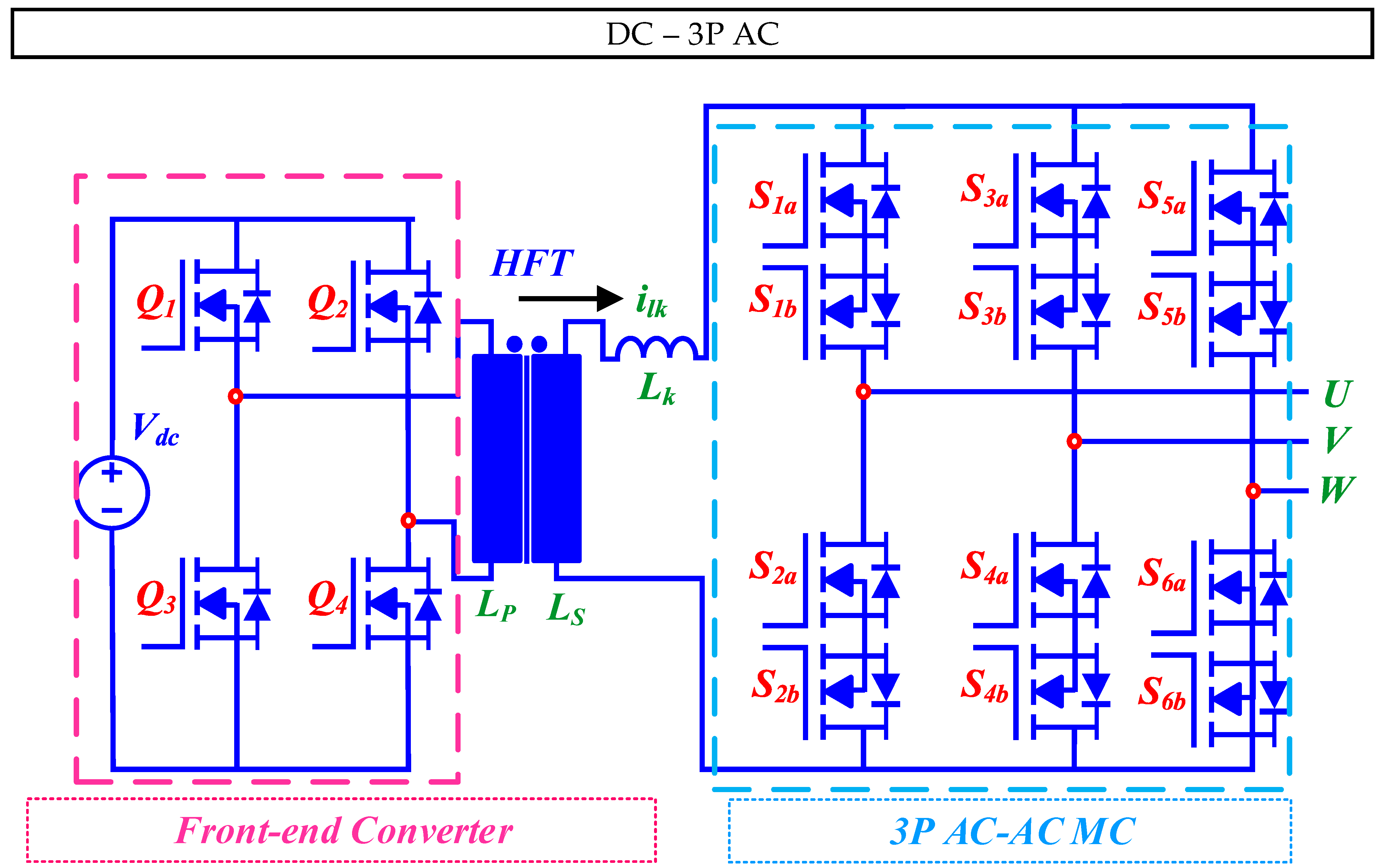
2.2.2. DC-3P AC Circuit

Recent scholarly works indicate a prevalence of single-inverter-based DC-3P AC circuits in the existing literature. Over the past few years, researchers have delved into various configurations, unveiling several noteworthy topologies, some of which are outlined below.

Single Inverter

DC to rear-end 3P AC MC-based topologies centering the modulation of switching semiconductor device gatings and optimal converter design are the current trending research focuses. Primarily, this topology incorporates a DC to 3P AC via a 1 × 3 MC circuit with AC-link HFT included as an intermediary stage. In [33], the authors report a similar topology. The front-end FBC is composed of four semiconductor devices S1S4. The rear-end 1 × 3 MC topology employs six bidirectional IGBTs Sxy (x = a, b, c and y = p, n). A DC filter capacitor is inserted before the front-end FBC to smooth the DC voltage feeding into the FBC so that it can output a bipolar primary HFT voltage. The secondary-side also incorporates an LC filter to ensure reactive power compensation of the system. This converter topology provides robustness and compactness of the network. The existing literature shows that conventional DC-AC circuits utilize a front-end FBC and a cascaded AC-DC rectifier followed by a DC-AC inverter with DC-link energy-storage capacitors placed in between the DC bus at the secondary side of the converter topology. This topology makes the system lose out in terms of power density. The MC proposed in this topology has adopted FCS MPC to generate gatings for a secondary-side MC circuit with an auxiliary output-current-tracking control method with steady-state compensation. However, a drawback of this control approach is that even though the MPC optimizes the cost function to select an optimal-state space vector for the gatings, the output of the MPC block is actually a modulation index parameter m which is being fed into the SVM block. Consequently, this approach introduces a degree of control complexity and calculation burden, seemingly a downside of this topology. In contrast to the conventional PI-controller-based gating generation which suffers from control complexity in terms of control-target error and environmental-variance factors, this converter effectively fulfills its control objectives with the MPC modulation scheme. The MPC control algorithm employed in this converter features a (a) converter stability, (b) low THDs in the output voltage waveform, (c) fine dynamic response with minimal overshoot with respect to the reference and load current variance, and (d) compensated leakage inductance using air-gap LCHFT. This type of converter topology is popular in WPT systems.
Figure 13 illustrates a generic key operating waveform of this converter. From this figure, we understand the cycle of the transformer’s primary-side switch signal, voltage, secondary-side switch signal, voltage, and inductive voltage, and the current for one cycle in sector I. In the first half of the cycle, the reference current vector is synthesized with the vectors iab, iac, i0. During the second half of the cycle, the vectors iba, ica, and i0 are synthesized, and the corresponding duty cycles of the bidirectional switches from Sap to Scn are 0.5T02, Tab, Tac, T01, Tba, Tca, 0.5T02, respectively.
In a similar study in [34], a configuration was introduced which combines a front-end FBC with a rear-end 1 × 3 MC topology, derived from Figure 13. A notable difference from the previously discussed topology is the inclusion of a leakage inductor on the secondary side of the HFT. This design ensures ZVS by employing the FBC with a fixed dead time. Moreover, ZVZCS is guaranteed for the rear-end 1 × 3 through an innovative modulation technique. This approach ensures that one upper switch from each phase leg aligns with low output frequency at all times, resulting in (a) reduced overall switching losses, (b) improved power density, and (c) enhanced system reliability.
In [35], the authors report a similar study for a DC-AC inverter. The primary-side FBC is regulated using a PS control method. PS modulation is a control strategy commonly used in the front end of an FBC in various applications, including RE systems and 3P AC motor drives.
Another DC-3P AC topology is introduced in [36], based on a front-end FBC and a rear-end 3 × 2 MC. The proposed converter is regulated using an asymmetrical SVPWM technique. The SVPWM initiates ZVS in the front-end FBC and ZCS in the rear-end 3 × 2 MC. Some key advantages of this modulation technique are it (a) reduces voltage spikes introduced by the HFT-side energy stored in the leakage inductor, (b) provides natural commutation to the current entering the AC-side of the inductor, (c) reduces additional requirement for RC snubber circuits which further leads to complex control of overlap-time and the dead-time compensation control technique, and (d) simpler control technique. Adoption of an asymmetrical SVMPWM technique in power converters to optimize the operation of the converter in situations where the desired output voltage or current waveform is not symmetric is an old method. The non-symmetric output voltage and current can occur in various powered electronic applications, such as motor drives, renewable energy systems, and grid-connected converters. The purpose of asymmetrical SVPWM is to achieve precise control of the output while taking into account the specific requirements of the application. Unlike traditional SVM, which assumes balanced and symmetric 3P systems, asymmetrical SVM recognizes the imbalances and asymmetries that may exist in practical scenarios. Similar to the popular FBC cascaded with 1 × 3 MC-based topology, researchers have also employed primary-side HBC cascaded with a secondary-side 1 × 3 MC circuit reported in [37,38,39,40,41]. This topology also reflects the conventional DC-3P AC inverter circuit structure. The standard configuration of such topology is similar to the topology depicted in Figure 13 for bidirectional EV charging and BSS applications. Using a primary-side HBC instead of an FBC cascaded with a secondary-side 1 × 3 MC in a DC-AC isolated inverter has its advantages and disadvantages.
Figure 13. HBC cascaded 1 × 3 matrix-based HFL DC-AC inverter [39,40] and (a) key operating waveform [33].
Electronics 13 00237 g013aElectronics 13 00237 g013b
In study [37], the authors report using an improved SVM technique to generate gatings for the HBC and the secondary-side 1 × 3 MC circuits. The topology offers some noteworthy features, e.g., (a) reduced low-order THDs, (b) improved duty-cycle calculation method, (c) two-step voltage-based natural commutation method, (d) zero sampling errors, (e) an optimized zero vector leading to the elimination of narrow pulses, and (f) low or nearly zero distortions in narrow pulse processing. The authors in [38], report a bidirectional DC-AC converter circuit similar to Figure 13. The MC is connected to the 3P grid via 3P capacitor bank acting as an input filter. The input AC filter assists in reducing unwanted grid-current harmonics and produces near sinusoidal grid currents to be fed into the 3 × 1 MC. Although, a minimal effect is experienced in the grid-side PF. However, the control algorithm minimizes this issue and produces UPF at the grid side. The proposed converter in this paper is actually seen in the rectifier mode, although bidirectional power flow in both the front-end and rear-end of the converter has ensured the inverter operation mode. The HBC in this circuit provides natural soft switching without the need of any auxiliary circuit components. Bidirectional-power-flow control is achieved by manipulating the switching patterns and duty cycles of both the MC and HBC. Therefore, the need for an additional leakage inductor on either the primary or secondary-side of the HFT is eliminated. Overall performance of the system depends on three control objectives: (a) power-flow control through the utilization of switching patterns and duty cycles in both converter at each side, (b) input DC current control, and (c) injection of sinusoidal currents to the grid at UPF. Several key attributes of this converter include (a) that additional dead time between the gating signals of the 3 × 1 MC and the HBC, leading to a natural soft-switching commutation of the HBC, (b) that a simple control algorithm cuts off additional delay in DSP response and execution time, (c) reduction in the overall system cost by elimination of the series inductors and resonant tanks in each side of the HFT, (d) duty-cycle accuracy of the MC due to independence on system parameters, and © low THD in the grid current. One major drawback of this converter is the discontinuous nature in the HFT current, which further reduces the system efficiency. However, all the effective features render this system exceptionally valuable for integrating BESS with RE sources into the future power grid, showcasing an impressive efficiency rate of 93%, as demonstrated in various case studies.
References [39,40] show a similar HBC cascaded 1 × 3 MC topology as depicted in Figure 13. In this circuit topology, the only visible difference is the parallel damping resistor located at the rear-end-filter 3P inductors. The bidirectional power flow of this converter is ensured via a phase-shift angle of the output voltages of the HBC and the 1 × 3 MC. A small capacitor is introduced at the DC-side to suppress unexpected DC current ripples. One key drawback of this converter is the capacitor current which affects the grid-side UPF. Furthermore, a notable distinction in this converter structure, compared to its predecessors, lies in the inclusion of a 3P capacitor bank on the grid side, complemented by series inductors. This addition not only incurs extra costs but also contributes to an increase in overall size. The key operating waveform for this converter is depicted in Figure 14a,b, showing the different analyses of duty cycles based on positive middle voltage and negative middle votlage.
In Ref. [42], a 3P SR DC-AC converter topology is proposed for V2G applications, featuring a front-end FBC and a rear-end MC with 4Q switches. The circuit diagram for this topology is similar to that of Figure 13. The front-end DC voltage source is connected in series with an inductor to work as a CSI. The input source is followed by a small capacitor to smooth any unwanted input-DC current ripples. The series’ resonant tank is placed at the front-end side of the converter and in series with the HFT to ensure ZVS of the FBC switches. This converter has also incorporated LC filters at the AC-side to downscale any uninterrupted grid harmonics feeding into the HFT. Subsequent research endeavors will concentrate on multiport configurations and enhance modulation techniques to eliminate HF harmonics within the tank circuit. Notable characteristics of this converter encompass: (a) simultaneous real and reactive power control in both directions, (b) high converter efficiency, (c) single-stage power conversion, (d) HF commutation, and © bidirectional power flow.
Numerous studies have explored multi-stage DC-3P AC circuit topologies. Common bidirectional dual-stage DC-AC topology is constructed via a DAB followed by a VSC which necessitates an intermediate DC-link capacitor. Acknowledging the issue, several research groups have investigated the functionalities, performance, and applications of a DC-link-less dual/multi-stage DC-AC network. A three-stage DC-AC converter circuit, as similar to the topology shown in Figure 13 employs a primary-side HB PWM rectifier, an HFT, and a secondary-side 1 × 3 DMC [43]. In order to achieve soft switching, the authors discuss adding a total of ten lossless-snubber-shunt ceramic capacitors in the circuit, which ideally makes the circuit more complex and cost-inefficient. Notwithstanding that, the efficiency of the converter is also susceptible to the usage of additional capacitors. In this network, ideally four parasitic ceramic capacitors have been added across the HB rectifier and an additional six capacitors have been integrated across the six semiconductor switches of the 3 × 1 MC network. A phase-shifted PWM technique with a 50% duty ratio has been employed for the primary-side converter network. This modulation technique is also another strategy to achieve soft-switching current commutations. However, for practical implementation, an additional PI controller is required to smoothly control the PS angle between the input and output voltages of the HFT which increases complexity for the control approach. The HB rectifier with a phase-shifted modulation technique converts a constant DC battery voltage to a HF square-wave 1P waveform. One key drawback of square-wave approximation is that it introduces additional harmonic spectrums in the grid current. To mitigate this problem, accurate mathematical model derivation is associated with the HF current and the duty ratio of the MC, which has high research potential. Next, the 1P AC goes through the HFT and becomes a more stable HF AC 1P waveform. This HF AC waveform is being fed back to the bidirectional 3 × 1 MC circuit and finally outputs 3P sinusoidal output which is basically connected to a 3P grid. This topology achieves ZVS for all oncoming switches and ZCS for all off-going switches, which also ensures reduced switching-power loss of the circuit topology. Overall, this network has the two following advantages over the aforementioned topologies: (a) high power density and (b) high efficiency.
An IMC-based topology is presented in [44] derived from the topology shown in Figure 13. The rear-end 1 × 3 MC is replaced with a PWM-diode rectifier followed by an indirect MC-based topology with a bulky DC-link inserted between the secondary-side converters. Although, this configuration projects a conventional isolated DC-DC converter at the secondary side, additional diodes and the inclusion of bulky DC-link capacitors contributes to increased system weight and additional costs while potentially reducing the lifespan of the converter.

2.3. Matrix-Integrated Single-Stage Isolated AC-DC Rectifier Topology

Matrix-integrated single-stage isolated AC-DC rectifier topologies can function similarly to DC-AC MC-based inverters, especially when integrated with MC, FBC, or HBC, enabling bidirectional power flow. Inside the single-stage MC-based HFL rectifier type AC-DC topology, different converters are employed at the secondary side of the circuit. Diverse converter drive techniques are prevalent in the secondary side of the AC-DC topology, e.g., (a) FB rectifier drive, (b) HB rectifier drive, (c) diode-rectifier drive, and (d) PWM-rectifier drive. A few DAB-type MC-based FB rectifier topologies have been documented in the literature [45,46,47]. However, we opted not to delve into these particular topologies due to their extensive number of subvariants, which did not align with the primary focus of our review. Three common single-stage AC-DC rectifier-based topologies: (a) DAB, (b) current-fed, and (c) voltage-fed have been identified in [48]. Each of these circuit configurations exhibit bidirectional-power-flow capability. In a separate study [49], AC-DC rectifiers are categorized based on (a) Buck Type and (b) Boost Type circuit networks. However, these two topologies are not conducive to bidirectional operation. The single-stage AC-DC rectifier topology emerges as a promising contender, effectively overcoming the challenges and issues encountered with its dual-stage counterpart. These challenges encompass, e.g., (a) low efficiency, (b) circuit complexity, (c) bulky boost inductor, and (d) DC-link capacitor requirements. The categorization of the isolated AC-DC rectifier topologies commences with its power-conversion-phase type at the source side. The basic circuits can be categorized as (a) 1P AC-DC rectifier, and (b) 3P AC-DC rectifier structure, as shown in Figure 1 with pink ink.

2.3.1. 1P AC-DC Circuit

Based on our literature review, a common 1P AC-DC circuit can be classified into (a) DMC-based and (b) flyback-integrated rectifier. DMC-based topologies have two subvariants including (a) resonance-based rectifier and (b) resonance-less rectifier. Subsequent sections will comprehensively discuss these topologies.

2.3.1.1. Resonance-Based Rectifier

AC-DC rectifier topologies with resonant tanks are documented in [50,51,52,53]. Reference [50] presents a bidirectional WPT system utilizing a resonance-based 1P MC and a rear-end HBC depicted in Figure 15.
This system incorporates a HFT for transferring power between the primary and secondary converters, with bidirectional power flow controlled by adjusting the phase-shift angle between the primary and secondary voltages of the transformer. In terms of modulation and control, this topology operates all switches at a 50% duty cycle and a specific switching frequency to generate a phase-shifted voltage. The magnitude and direction of power flow are determined using the phase-shift angle. Some interesting features of this topology include (a) a reduced number of conversion stages, (b) eliminating the need for a bulky DC-link capacitor, and (c) achieving bidirectional power transfer in a single stage. The use of an MC also offers benefits like size reduction, low weight, cost-effectiveness, high efficiency, HP density, and noise decoupling. However, it comes with challenges related to power loss and the need for compensation for leakage inductance. Applications for this converter topology span a wide range, including EVs (in both V2G and G2V power transfer), implanted medical devices, solar-powered satellites, unmanned aerial vehicles, smart homes, and man-made satellites.
In Figure 15, the typical mode of operation of switches and the working principle of such an isolated AC-DC rectifier can be observed. The δp and δs parameters are the phase-shift angles between two legs of the MC and the HB. From these delta values, a PS of Өd in v11 and v22 will be introduced. The PS angle determines the amount of current absorbed or delivered by the grid. Өd is positive and negative depending on whether v11 leads or lags v22. G2V is activated when v11 leads v22, and V2G is activated when v22 leads v11. δp angle is always maintained at 180 degrees.
Additionally, another resonance-based isolated 1P AC-DC Buck MC topology is proposed in [51] for DVR applications as shown in Figure 16. In this topology, the total number of switches count of the proposed MC is six. Four IGBTs in the primary-side construct the front-end converter, and two IGBTs in the secondary-side construct the rear-end converter. Altogether the six IGBTs work as an MC topology. One key aspect of this topology, is that the realization of the circuit can be achieved through two different secondary-side circuits, distinguished by the nature of their output current, either (a) continuous or (b) discontinuous. The two secondary side switches (S5-S6) can be employed in specific configurations to realize the circuit in these two distinct ways. This is how the rear-end HFT isolation semiconductor switching devices of the MC functions in two different ways. One of the key advantages of this topology is that it eliminates the requirement of any bulky passive-energy-storage elements and line-frequency transformer, which confirms rapid power density of the converter and a low-cost approach for designing the topology. Soft-commutation has been employed to resolve the commutation problems, specially to avoid (a) any high-shoot-through current through the front-end IGBTs during the overlap-time when all the switches are ideally turned on as well as (b) any high-voltage surge reflected back on the primary-side of the converter during dead-time when the leakage inductor current cannot pass through towards the primary side of the HFT due to a freewheeling current loop circling around the input passive element Cin which also risks short-circuit situation. The soft-commutation strategy of this topology eliminates a shoot-through current commutation scenario and abnormal switching voltage spikes via overlap-time and dead-time compensation techniques, which also further minimizes the necessity of additional RC snubber circuits. Key advantages of this MC circuit are (a) variable output-voltage drive including in-phase, out-of-phase, and rectified 3P voltage waveform, (b) stepper output frequency modulation technique, and (c) AC HFT galvanic isolation.

2.3.1.2. Resonance-Less Rectifier

In [52], the authors propose a matrix-integrated single-stage isolated resonant tank-less 1P AC-DC rectifier topology which is an HFT-based converter consisting of a primary-side MC and secondary-side HBCs as demonstrated in Figure 17. It incorporates modulation and control techniques that employ soft-switching methods. Advantages of this topology encompass (a) enhanced efficiency, (b) reduced switching losses, and (c) minimized EMI. However, the challenges include increased system complexity and the requirement for precise control. This converter topology holds promise for a range of applications, including use in RE systems, EVs, and power electronics.
In Figure 17a,b, two key operating waveforms for the voltage current of HFT around the peak of source voltage as well as at the low source voltage have been visualized, respectively.

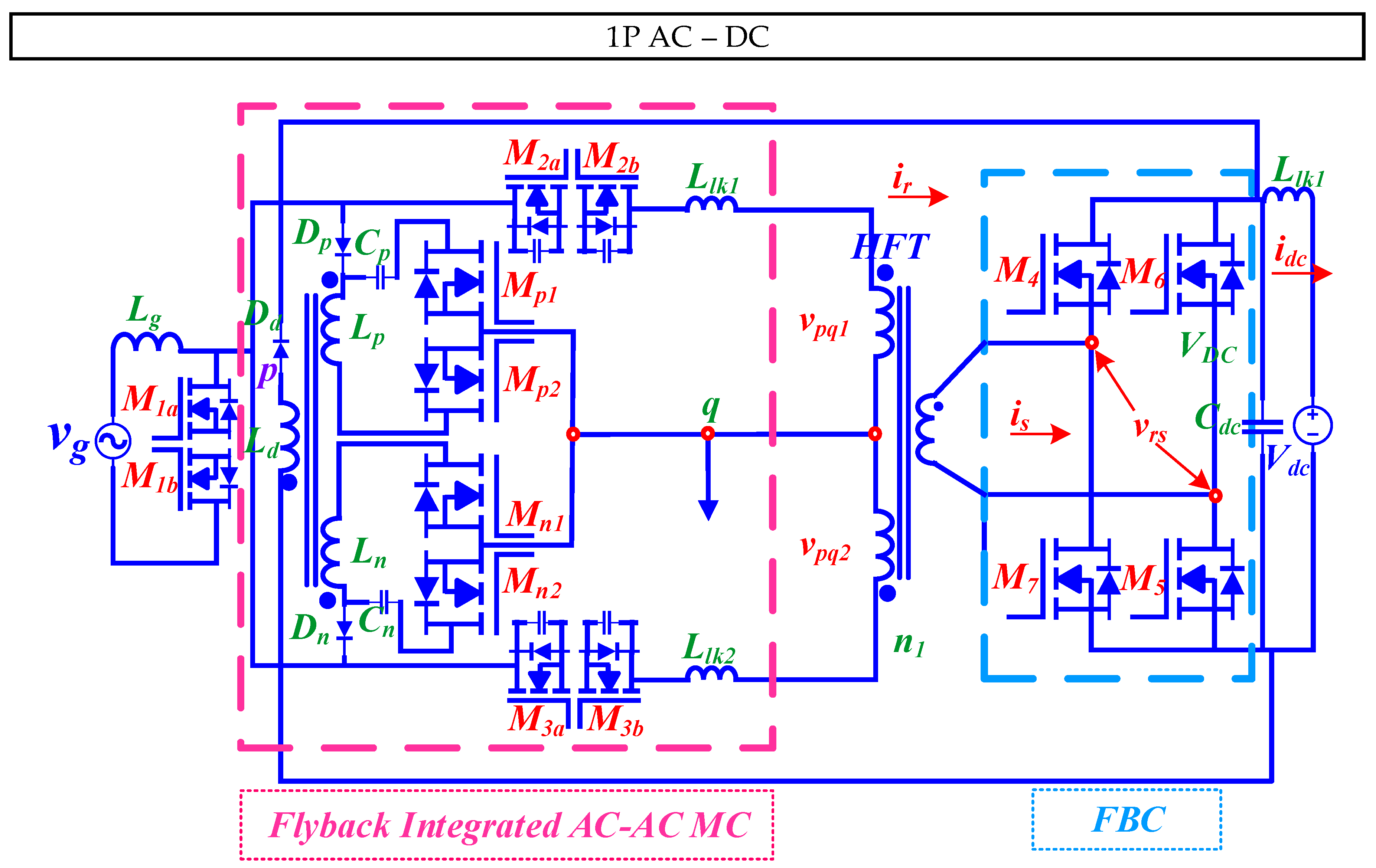
2.3.1.3. Flyback-Integrated Rectifier

In [53], the authors introduce a novel isolated single-stage bidirectional MC-type AC-DC rectifier topology with a flyback-based clamp circuit destined for EV battery-charging applications as shown in Figure 18. Primary AC-side employs a standard HB cycloconverter derived from conventional 3 × 1 MC and a rear-end FBC. To control the power flow in both G2V and vehicle V2G modes of operation, a soft-switched UPWM scheme is implemented. The special clamp-integrated MC circuit is designed to facilitate smooth current commutation through the filter inductor and the leakage inductor of the AC-side HFT. A notable feature of this clamp circuit is its ability to regenerate energy. It effectively recycles the energy stored in the clamp capacitors twice during a switching cycle, resulting in an overall improvement in power conversion efficiency.
The circuit operation over a switching period Ts is segmented into ten intermediate modes, as illustrated in Figure 18. The grid voltage vg and the DC bus voltage Vdc are assumed to remain constant throughout the switching period Ts at the steady state. Although the devices employed in the converter are assumed to be ideal, their body diodes and output parasitic capacitors are considered to elucidate the converter’s operation.

2.3.2. 3P AC-DC Circuit

The 3P AC-DC rectifier topologies have been categorized based on: (a) DMC-based, and (b) 3P VSC-based MC-type AC-DC rectifier. The DMC-based rectifiers have been further subcategorized as: (a) single rectifier, (b) cascaded rectifier, and (c) MMxC rectifier respectively. These topologies have been broadly explored in the following sections.

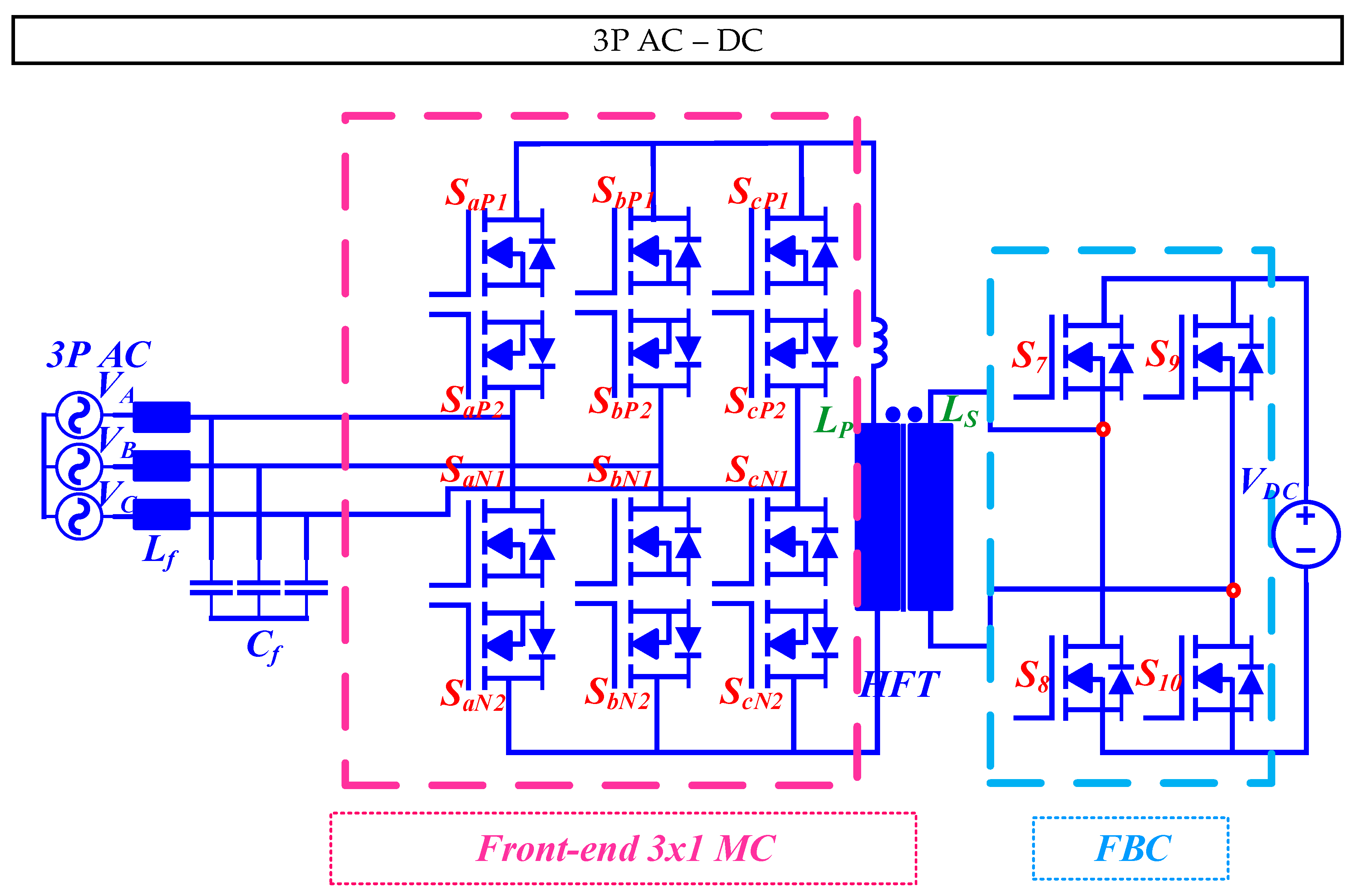
2.3.2.1. Single Rectifier

The researchers in [54,55], propose a single-rectifier-based topology that incorporates rear-end FBC cascaded with a front-end 3 × 1 MC-based circuit as illustrated in Figure 19. The later topology shown in [55] employs a damping resistor with the input LC filter. A similar topology is reported in [56]. The proposed topology introduces a decoupling control method based on the HFT’s physical model to eliminate the DC bias flux. This topology offers several advantages, notably (a) the removal of DC bias flux within the transformer, (b) enhanced controllability of the output current, and (c) the potential for a more compact size and increased efficiency when compared to alternative topologies. However, this topology presents specific challenges, including (a) the necessity for effective decoupling control between the primary and secondary sides of the HFT, and (b) addressing LF pulsations stemming from cross coupling between the MC and FBC control. Potential applications for this converter topology encompass AC-DC converters integrated into systems featuring storage batteries connected to AC networks, as seen in RE systems and EVs.
A soft-switching method is employed in this 3P MC-based FB rectifier topology [57], similar to the topology demonstrated in Figure 19. This topology utilizes a QR modulation strategy, ensuring soft-switching operation for all semiconductors over a broad operating range. Noteworthy advantages of this configuration encompass an enhanced efficiency, as demonstrated by experimental results achieving 96.5% efficiency at nominal power. Importantly, this efficiency remains consistently high across the entire operating spectrum, distinguishing it from conventional converters. Nevertheless, challenges persist, notably voltage ringing within the MC, which is not entirely mitigated by the modulation strategy alone. To address this, minimizing the HFT’s leakage inductance is crucial to reduce duty-cycle losses associated with MC commutations. This converter topology finds promising applications in integrating distribution generation, energy storage, DC microgrids, and EVs within AC distribution systems. Its versatility extends to battery storage, EV chargers, and serving as an interface converter for DC microgrids.
A typical 3P AC-DC rectifier topology [58], referred to as isolated AC-DC MC IAMC, comprises: (a) an input LC filter, (b) a 3P-to-1P AC-AC MC, (c) an HFT, (d) an HBC, (e) an output LC filter, and (f) a DC load. The modulation strategy applied in the converter is the bipolar current SVM (B-C-SVM). This topology offers several advantages, including (a) commendable input and output performance, (b) minimal power conversion stages, (c) the absence of a need for large-capacity energy-storage elements, and (d) bidirectional energy flow. Furthermore, it achieves simultaneous grid-side PFC and harmonic suppression, leading to simplified control system architecture and enhanced control accuracy. However, it faces challenges, particularly related to the phase difference between grid-side voltage and current introduced by the input filter. To mitigate this, the topology incorporates virtual capacitors and virtual resistors. Potential applications for this converter topology encompass ESS, wind-power systems, rail transit systems, and DC microgrid systems. Researchers have proposed a similar configuration in [59], comprising a 3 × 1 MC, an HFT, and an HBC. An SVM strategy is implemented to enhance power quality and reduce switching actions in both the 3 × 1 MC and HBC. This topology offers several advantages, such as (a) increased power density and (b) reliability when compared to traditional solutions. It also provides galvanic isolation without requiring intermediate energy-storage components. Nevertheless, it faces challenges related to (a) power quality, (b) commutation, and (c) the need for efficient coordination of PWM signals to ensure power transfer. Potential applications for this converter topology encompass V2G systems, ESS, and hybrid microgrids.
In [60], a bidirectional isolated grid-tie AC-AC-DC converter is introduced. It consists of two key components: (a) a MC responsible for converting the grid’s 3P voltage into a HF square-wave 1P voltage, and (b) a HF HBC that converts this HF square-wave voltage into a DC voltage. These converters are interlinked by an HFT. The proposed modulation technique in this configuration is a PWM switching technique. It offers precise control over the DC voltage and current, ensuring UPF at the grid side. For controlling the DC voltage and current during battery charging and discharging, a conventional PI controller is employed. The advantages of this topology are notable and include (a) high power density, (b) high efficiency, and (c) the elimination of bulky components like the DC-Link capacitor and 3P isolating transformer. Furthermore, the proposed technique successfully achieves UPF at the grid side. However, it is worth mentioning that challenges exist, notably in the form of high current and voltage ripples, as well as relatively lower efficiency when using the previous switching technique. This converter topology holds promise for a variety of applications, including systems designed for battery charging and discharging, the integration of RE sources, and grid-tie applications.
The authors report an MC-based HB rectifier topology, utilizing the modified SVM technique in [61]. While the specific control strategy is not detailed in the paper, the advantages of this design encompass: (a) bidirectional power flow, (b) high power density, and (c) a reduced number of power conversion stages. It is important to note that this approach also presents certain challenges, including (a) increased complexity, (b) higher switching losses, and (c) elevated voltage stress on the power devices. Potential applications for this converter topology extend to RE systems, EV charging stations, ESS, and microgrids.
In [62], the authors report a bidirectional AC-DC MC-based topology with a two-stage switch in the rear end. It utilizes PWM for the front-end converter, based on the fitting of the maximum input voltage, while the rear-end HBC employs a control method similar to synchronous rectification. This topology offers several advantages, including (a) the achievement of a sinusoidal grid current and UPF in both rectifier and inverter modes, and (b) a constant output current exhibiting less than a 3% ripple. It is characterized by high efficiency, high power density, low current harmonics, bidirectional energy flow, and unit power factor operation. However, the use of bidirectional switches in this topology results in reduced system efficiency due to an increased on-state voltage drop. The complex structure and control of the bidirectional isolated AC-DC MC also present challenges for its implementation. Key applications of this converter include energy-storage systems and EV V2G systems.
Similarly, in [63], the authors present a 3 × 1 MC which functions as a Buck-type rectifier and a Boost-type inverter in a single stage, facilitating the connection with lower DC voltage sources. This topology introduces a new SVM strategy with two-step commutation, ensuring safe commutation and minimizing current distortions during the process. It achieves this by always commutating between phases with detectable differences in instantaneous voltage amplitude and optimizing the distribution of zero vectors. Advantages of this design include (a) high power density, (b) low power loss, and (c) an extended expected lifetime due to the elimination of DC-link capacitors. It is well-suited for applications like EV charging, ESS, and hybrid AC-DC microgrids. Challenges associated with this topology involve the coordination of PWM signals between the 3 × 1 MC and the HBC to attain sinusoidal current and ensure the safe commutation of bidirectional switches. Additionally, relative voltage magnitudes and handling narrow pulses during commutation present challenges.
The authors in [47,64] report a 3P MC-based AC-DC converter featuring a short-circuit leg. It relies on six gate drivers to transform 3P AC into MF AC, which is then stepped down and rectified for battery-charging applications. The converter utilizes a SVM strategy and closed-loop control to regulate the input PF and battery current. Key advantages of this topology encompass (a) enhanced efficiency, (b) power density, and (c) reliability when compared to conventional two-stage converters. It achieves soft-switching for all active devices, eliminates body-diode conduction, and enables high-frequency operation with complete ZVS. Additionally, the reduced number of isolated drivers and associated power supplies contributes to improved converter reliability. However, challenges exist in this topology, including effectively managing the energy stored in the transformer’s leakage inductor, which is addressed through the incorporation of an additional short-circuit leg to ensure a continuous path for the leakage energy. The reliability of the operation may also be influenced by potential gate driver failures, as these components are critical in power converters. This converter topology finds suitability in battery-charging applications, particularly for integrating BESS with the utility grid. It offers bidirectional AC-DC conversion with galvanic isolation, making it applicable to systems like V2G and ESS.
An AC-DC isolated MC topology, often referred to as MCharger is presented in [65]. It makes use of an MC to directly perform AC-AC energy conversion, eliminating the need for a separate rectifying stage. The system includes an HFT with low leakage inductance, an HBC, and an LC filter for rectification. The modulation strategy employed in this topology is a 4-STEP switching procedure, which generates 12 gate logic signals from six modulation signals. This method facilitates the generation of the desired output voltage and manages the AC transformer current polarity. Notable merits of this converter include its capability to provide current and voltage regulation for ES devices, like EV batteries. It offers a wide output voltage range from 50 V to 500 V and can handle a maximum power of 25 kW. The use of the MC and the low leakage inductance of the isolation transformer helps reduce transformer voltage drops and improve efficiency. Challenges with this topology may include the complexity of the modulation strategy and the need for careful design of the isolation transformer with low leakage inductance. Applications of such converter generally revolve around level I chargers for EVs and other applications that require DC power.
An interesting isolated input LCL type 3P AC-DC rectifier that integrates an ES element, such as a battery, with the utility grid is proposed in [66]. The ideal converter structure is shown in Figure 20. It employs an MC-based AC-AC converter for 3P-to-1P conversion, a HFT for galvanic isolation, and a FBC controlled rectifier section for AC-DC conversion. The modulation technique used in this topology consists of SVM for the MC, enhancing input-power quality, and SPWM for the FBC controlled rectifier. This topology offers several advantages, including (a) superior input power quality, (b) improved power conversion efficiency, (c) HV conversion gain, (d) a HP factor, and (e) increased power density. It also allows bidirectional power flow and facilitates a smooth transition of power-flow direction. However, one challenge is the need for a comprehensive modulation technique to reduce THD due to the input LC filter. Popular converter applications include integrating ES elements such as batteries or supercapacitors with the utility grid. It finds utility in various applications, including aircraft systems, telecommunications, micro-grids, and ES systems.
Similar topology with a secondary-side diode bridge rectifier is incorporated into the AC-DC rectifier topology as reported in [67,68,69,70,71,72,73] references. A standard topology of such a converter is shown in Figure 21. However, in contrast to the rear-end FB or HB AC-DC circuit topologies, this secondary-side diode-rectifier configuration operates strictly in a unidirectional manner. Two innovative variations from this topology are known as (a) buck-matrix-type, and (b) boost-matrix-type converters and are reported, respectively, in [71,73]. In a diode rectifier converter, diodes are arranged in a specific configuration, such as a bridge rectifier, to perform the rectification process. When HF AC voltage is applied to the input of the diode rectifier converter, the diodes conduct during the portions of the AC waveform where their anode-to-cathode voltage is positive. This allows the positive half-cycles of the AC voltage to pass through, while blocking the negative half-cycles. The result is a pulsating DC output with ripples, which can be further smoothed using filtering components like capacitors to obtain a more constant DC voltage. Diode rectifier converters are simple and cost-effective but are typically used in applications where a fixed DC output with some ripple is acceptable, as they do not provide precise control of the output voltage. Diode rectifiers are often used in low-power applications, such as in power supplies, battery chargers, and simple voltage-rectification tasks. For more advanced applications requiring controlled and regulated DC output, other types of rectifiers, such as thyristor-based rectifiers or semiconductor switches like IGBTs, might be used.
Another special boost-matrix-type diode rectifier topology is presented in [73], which shows advantages in achieving soft switching for all switches, reducing conduction loss, improving system efficiency, and using conventional PWM technology derived from the topology shown in Figure 21. However, challenges are associated with the requirement for additional components, such as the clamping capacitor and commutation inductors, and the complexity of the soft-switching process found in other topologies. This converter topology is well-suited for single-phase high-power PFC applications where high efficiency and reduced conduction loss are crucial.
Several studies have explored MC-based PWM rectifiers [74,75,76]. Notably, the authors report an isolated AC-DC converter designed for rapid battery-charging applications based on PWM rectifier [75]. It incorporates an MC with both discontinuous current mode (DCM) and CCM operation to meet the demands of quick charging. A notable feature of this converter is the replacement of the boost inductor with an MF AC inductor linked to an MFT, resulting in a more compact design. SVM is employed as the modulation technique to calculate the duty ratio for the converter, and the control method combines voltage-based commutation with two-level compensation, utilizing linear approximation to reduce voltage error and input current distortion. Advantages of this topology include (a) its compactness, (b) enhanced efficiency achieved through fewer conversion stages, and (c) reduced size and weight. Nevertheless, it faces challenges related to input current distortion due to the small medium-frequency inductor and potential transmission power errors arising from voltage errors during commutation. The proposed compensation method is introduced to tackle these challenges. This converter topology is particularly well-suited for rapid battery-charging applications in EVs and PHEVs. It offers the potential for benefits such as weight reduction, size reduction, and improved overall efficiency.

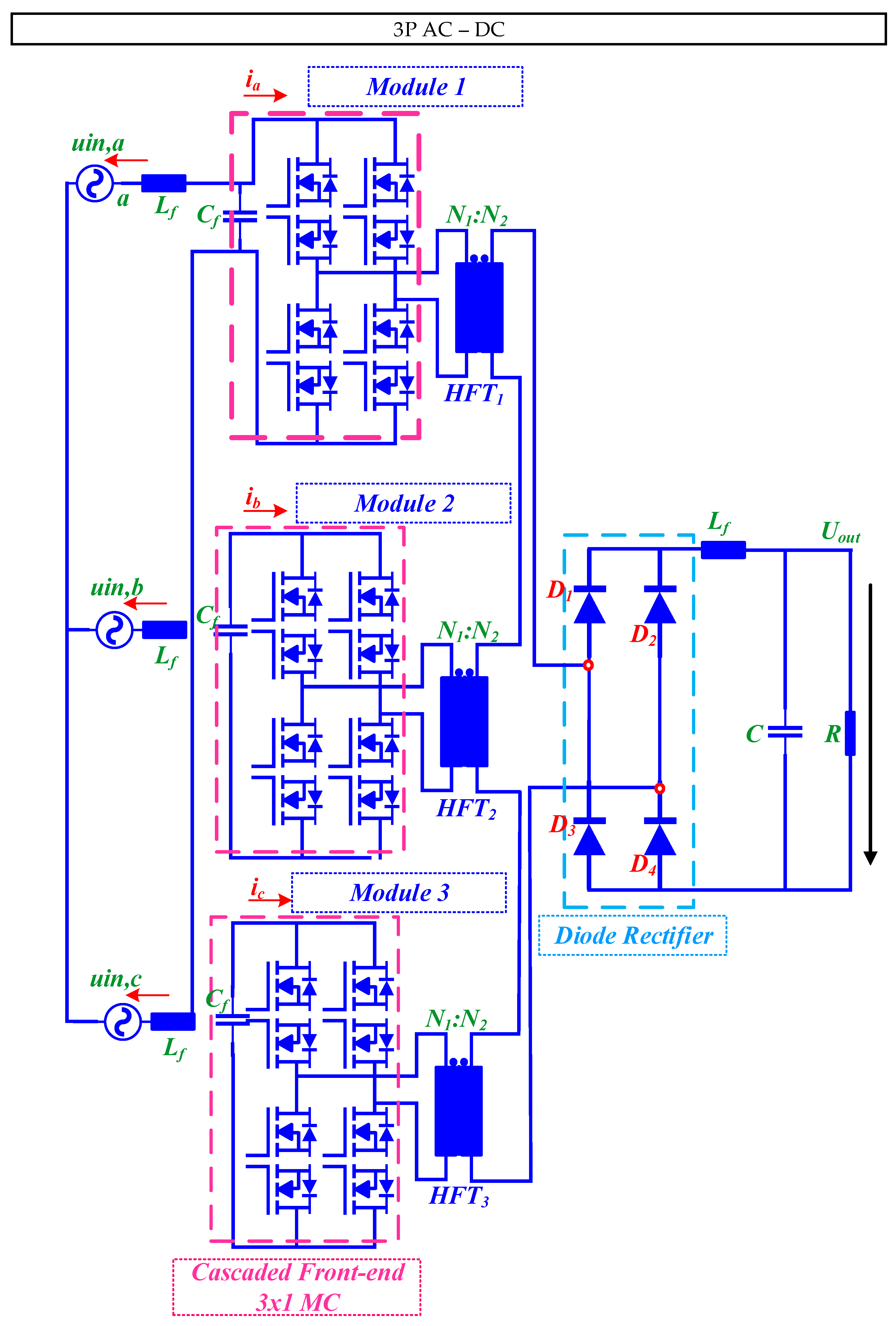
2.3.2.2. Cascaded Rectifier

An innovative cascaded 3P AC-DC topology known as isolated matrix-type y-rectifier (IMY-Rectifier) is presented in [67]; it involves a star connection of 1P mains frequency to HF AC-AC MCs at the input. The circuit configuration is shown in Figure 22. These MCs feed HFTs. The secondary windings of the transformers are connected in series to the input of a diode rectifier with an LC output filter. The modulation and control scheme applied to this topology ensure constant power flow and a constant output voltage. It actively controls the potential of the star points of the phase modules, eliminating the need for a connection to the mains neutral. Simulation results validate the operation of the new control scheme. Noteworthy features of this topology include (a) controlled output voltage, (b) sinusoidal input currents that are in phase with the mains voltages, and (c) the ability to provide galvanic isolation of the output voltage. However, it requires a larger number of semiconductor devices compared to a phase-integrated 3P rectifier. The voltage stress on these devices is lower, allowing for the use of lower voltage rating power switches. Challenges include the complexity of the topology and the need for careful design considerations. This converter topology finds applications in various scenarios, including PF correction rectifiers, high-frequency AC sources, and constant-current supplies. The article also presents alternative topologies, such as the Boucherot-IMY-AC/AC-Converter and dual Boost-type alternatives.

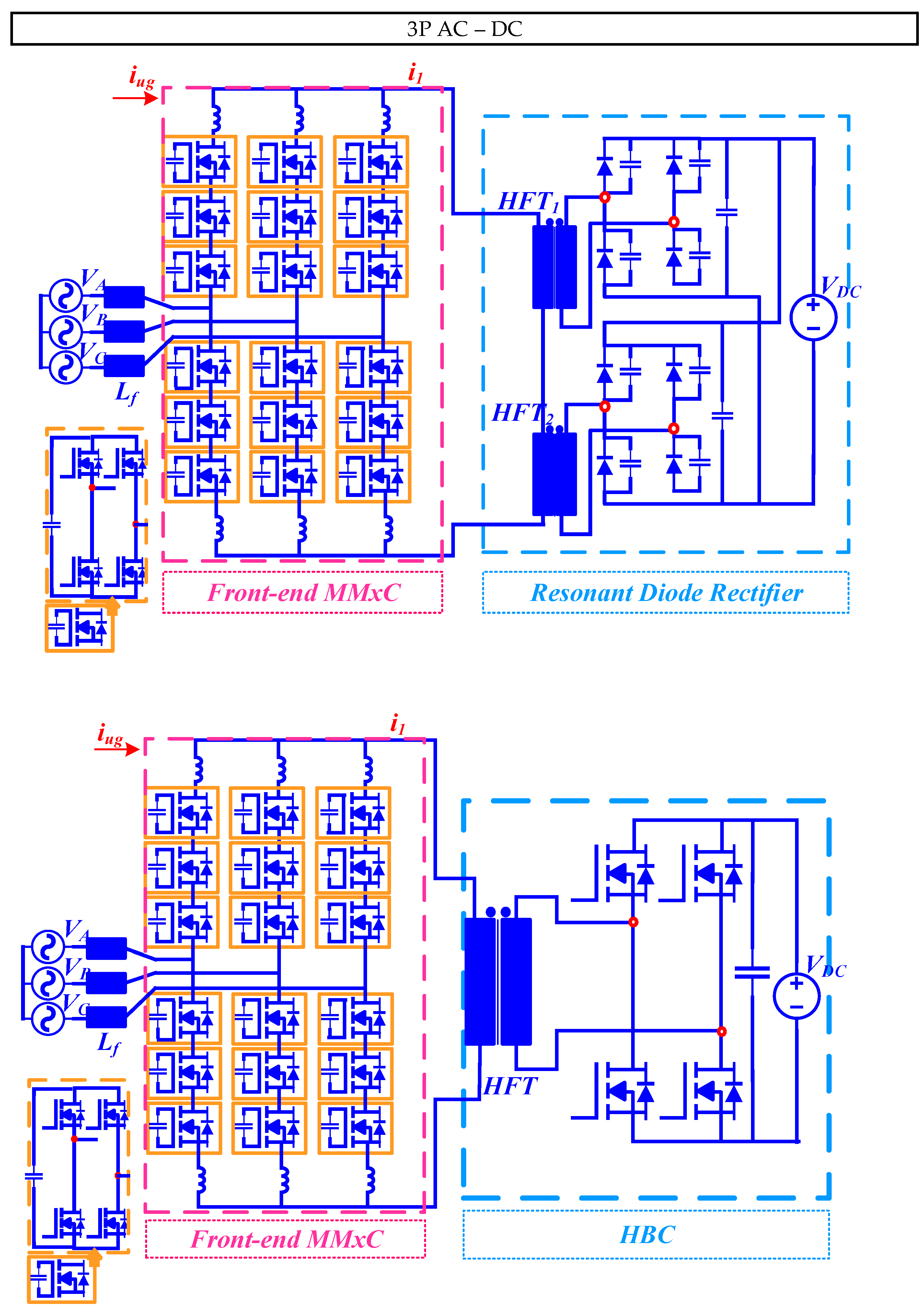
2.3.2.3. MMxC Rectifier

The MMxC 3P AC-DC is comprising six arms, with each arm consisting of three modules connected in series. Each module is equipped with an HBC and a DC capacitor. It is crucial to maintain balance in the DC voltages across all the capacitors in the MMxC to ensure the stable operation of the converter. Quite a few studies have reported incorporation of MMxC-based rectifier topologies in [77,78,79,80]. Currently, there are two subvariants present for the topology. One is the rear-end resonant diode-rectifier circuit and the other one is rear-end HBC circuit. The typical circuit diagram of such a topology can be found in Figure 23.

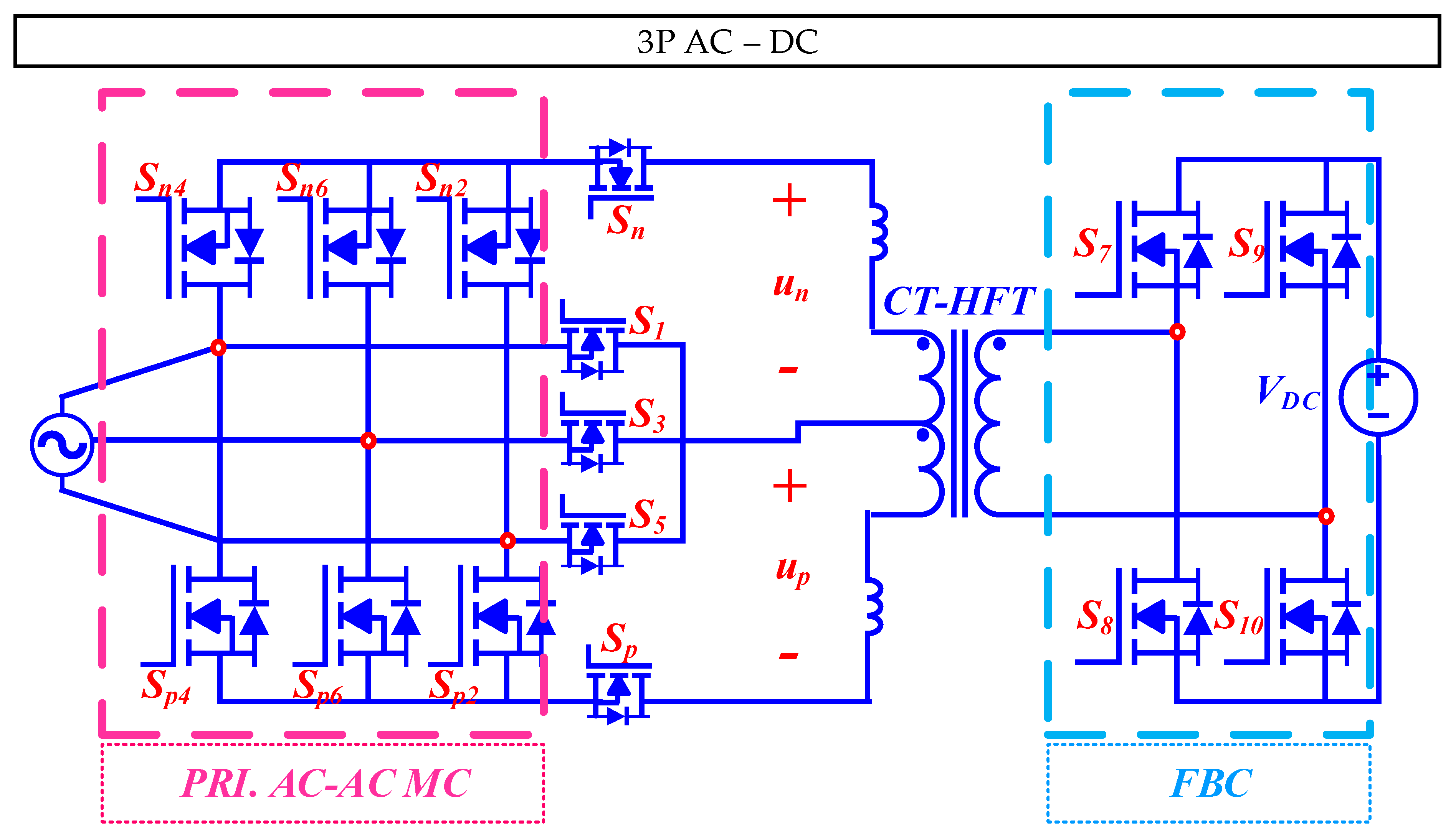
2.3.2.4. 3P VSC-Based MC-Type AC-DC Rectifier

A special MC-based circuit topology is proposed in [81] as shown in Figure 24. The proposed topology uses a 3P VSC-based isolated MC-type AC-DC converter. It consists of three main parts: (a) front-end 3 × 1 MC, (b) a CT-HFT replacing two cascaded HFTs, and (c) a rear-end FBC. The MC is composed of two VSCs that alternately work during each switching cycle, eliminating the need for bidirectional power switches. The uniqueness about this front-end MC-based structure is the adoption of 11 bidirectional power-switching devices. The armature windings of the HFT are used as input filters, and no additional inductor or capacitor is required. The HFT replaces the line-frequency transformer used in conventional systems. The HFT includes leakage inductors Lkp and Lkn caused by the leakage flux and cannot be eliminated completely in practical transformer design. Among the defining features of this converter are (a) elimination of bidirectional power switches, simplifying the commutation process and reducing additional conduction losses from serially connected power switches, (b) elimination of intermediate electrolytic capacitors, enhancing reliability, power density, and system efficiency, (c) increased high power density, reducing the heat sink volume and enhancing the overall system efficiency, (d) modular structure for high power conversion, further facilitating large power-transfer capacity for offshore WFs, (e) simplified control and gatings, by avoiding the need for a four-step commutation process and employing voltage vectors-based SVM, (f) wide operation range by maintaining a constant amplitude of the leakage-inductor current, even in the presence of voltage mismatches on both sides of the HFT, and (g) elimination of RC snubber circuits for switching power devices. The authors in this study do not explicitly mention any challenges and pitfalls of the proposed converter topology, but based on the information provided some potential challenges could include (a) HFT design, (b) switching-power losses, (c) limited switching frequency, and (d) voltage and current stresses. The proposed converter topology uses voltage-vectors-based SVM for control and simplifies the commutation process by eliminating bidirectional power switches and employing a two-step or three-step commutation scheme. The proposed converter topology is intended for use in WECS, particularly in offshore WFs and isolated grid-tied inverters, to improve efficiency, reliability, and power density. The same research group proposed a similar topology in [48]. The modulation and control strategies implemented in this topology closely resemble those of VSCs, with the use of a voltage-vector-based SVM scheme. Key advantages of this design encompass (a) heightened power density, (b) enhanced system reliability, (c) minimized conduction losses, and (d) reduced computational burden when compared to alternative MC topologies. Notably, it eliminates the necessity for filter capacitors on the 3P grid side and extra inductors on the DC side, leading to a reduction in overall system size and weight. Furthermore, the proposed topology achieves soft-switching operation. Nonetheless, certain challenges persist within this configuration, including (a) the presence of HV spikes during the commutation process, and (b) the emergence of circulating currents, contributing to additional conduction losses. Additionally, the computation of dwell time for the direct AC-DC matrix converter (DAB-MC) proves to be more intricate compared to the other MC-types. This converter topology shows promise in applications such as WECS, WPT, ESS, and V2G systems.
In the following three pages, three concise summary and comparative analysis of all the matrix-integrated single-stage isolated MF/HF converter AC-AC/DC-AC/AC-DC topologies are tabulated. These tables contain a compare–contrast of different advantages/disadvantages as well as a performance analysis (efficiency, cost analysis, control complexity, etc.) of matrix-integrated converter topologies. Table 1 shows the summary of matrix-integrated single-stage isolated AC-AC converter topologies. A total of six topologies have been discussed and their performance has been analyzed. Again, in Table 2, a concise summary of matrix-integrated single-stage isolated DC-AC inverter topologies have been presented. A total of three topologies have been discussed, and their performance has been analyzed in a similar manner. Finally, in Table 3, a narrative summary of matrix-integrated single-stage isolated AC-DC rectifier topologies have been discussed. This table analyzes a total of 10 different topologies. All the tables include reference numbers for clarity. In instances where certain studies did not extensively address efficiency improvements, the review aims to elucidate any enhancements, be it through software analysis or experimental validation, providing a comprehensive overview of each study’s contribution to efficiency considerations. The presented tables crucially highlight the advantages and disadvantages of the matrix-integrated converter topologies. These assessments serve to underscore the strengths and weaknesses of each configuration. Moreover, a significant emphasis is placed on control challenges—a pivotal aspect for designers aiming to conceptualize and implement hybrid converter topologies. Understanding these control challenges is paramount in the design process for achieving optimal performance and reliability.

3. Modulation Techniques and Control Method of Matrix-Integrated Single-Stage Isolated MF/HF Converters

Efficient control methods play a significant role in enhancing the dynamic behavior of the MCs. Yet, modulation techniques are equally vital for ensuring smooth switching commutations within a circuit. A good MC topology can be identified as one that has a fine balance in control method and modulation techniques, thereby yielding benefits like (a) low switching losses, (b) minimum EMI, (c) reduced voltage and current stress, (d) rapid switching transition, (e) zero overvoltage and overcurrent, (f) damped transients, (g) synchronized switching commutation, and (h) adaptive control in the circuit.
Different MC modulation techniques are reported in the literature, e.g., ZVS+ZCS [20,22,53], 3P PWM [24], SVM [29,33,52], Modified SVM [28,37,38,39,40,41,57,59,67], PDM [31,35], Duty Ratio [42], PWM [60], Modified PWM [38,39,43], Nonlinear PWM [54], Sine-Triangle PWM [50], SPWM [66], Modified SPWM [41], DLVM [55], Staircase Modulation [51], and VVBM [81], etc.
Among them, the SVM technique has been quite popular. SVM stands out as a technique in power electronics, particularly in applications like motor drives and UPS, where maintaining precise control over the output voltage is crucial. According to the study [31], the PDM technique is applied to the secondary-side converter using a MC in order to reduce switching losses. PDM achieves ZVS by generating output grid voltage waveforms using the input voltage pulses of the MC as the minimum unit. This allows the MC to switch at the zero-voltage period of the third-winding of the coupled inductor, reducing the switching losses and improving efficiency. Additionally, PDM based on delta–sigma conversion is used to generate inverse voltage pulses that cancel the quantization error and reduce the distortion of the grid voltage, resulting in low output voltage THD.
Furthermore, PWM is a crucial technique in power converters, widely employed to regulate the output voltage by adjusting the width of pulses in a square wave signal. This technique is extensively used in various applications, including motor drives, power inverters, and voltage regulators. PWM involves rapidly switching between high and low voltage levels within a fixed period, creating a waveform with varying pulse widths. By altering the duration of these pulses, the average voltage delivered to the load can be controlled. PWM is favored for its efficiency in regulating power, reducing harmonic distortion, and enabling precise control of output voltage, making it a cornerstone in power electronics.
In [50], a special modulation technique derived from the general PWM as known as the sine-triangle PWM modulation technique has been reported to generate a sinusoidal control wave for PWM operation by comparing the ratio of two signals and then comparing it to a carrier wave of switching frequency to produce PWM pulses for the MC. This technique is used to avoid over modulation and ensure that the PWM pulses for the HBC are synchronized with the primary converter. In the study [66], SPWM is employed for the FB-controlled rectifier section for AC-DC conversion. The SPWM technique is used to generate the gating signals for the FB-controlled rectifier switches, which allows the converter to produce a sinusoidal output voltage with low THD.
DLVM is employed for the pre-stage circuit in the study [55]. This modulation strategy is used to realize the coordination of the pre-stage circuit and the post-stage circuit of the isolated bidirectional AC-DC matrix converter. It is employed to achieve balanced sinusoidal grid currents, nearly UPF, and low output voltage/current ripple.
The staircase modulation technique is a unique method used in AC-AC converters to improve the output power quality. In [51], the staircase modulation technique is applied to the proposed single-phase buck MC to enhance the quality of the output power. This technique is used to achieve various output voltages, such as IPOP output voltages, rectified output, and output voltage with step-changed frequency. The study presents the switching strategies and key waveforms of the proposed MC for IPOP mode operations, which are part of the staircase modulation technique.
VVBM is employed in the proposed converter in reference [81]. This modulation method is used in the context of the proposed matrix-type AC-DC converter, where voltage vectors are employed to achieve space vector modulation. The modulation method is based on the use of voltage vectors to control the switching of the power switches in the converter, allowing for efficient and controlled power conversion.
Table 4 presents a succinct and clear summary report of various modulation techniques applicable to matrix-integrated single-stage isolated MF/HF converter topologies. The table delineates the characteristics of each modulation technique along with their specific applications, aiding designers in understanding how and when to employ these modulation techniques.
From this table, we can piece together a clearer idea about different features of the modulation techniques and their applications.
Some popular control methods are reported in the existing literature, e.g., EIC [20,21,53], LITC [22,81], SBCC [24], PSVDC [28], PEC [29], DMO [31], FCS MPC [33], PSC [35,42,43,44], PFC [37,38,39], DCC [40], Acom. [41], IPOPC [51], SSC [52], DPC [56], UPFC [58], LOHMC [59], BPFC [60,66,67], etc. Among all these control methods, only FCS MPC is a predictive control technique that necessitates analysis of an algorithm for future predicted models of the output load current. Apart from that, all the other control methods have specific control objectives and they must be met in order to be able to successfully perform efficient power conversion from either grid–grid or grid–HVDC or vice versa. A comparison of all the common control methods has been outlined in Table 5.
Table 6 offers comprehensive design specifications for various matrix-integrated single-stage isolated MF/HF converter topologies. Serving as an effective guide for designers seeking to comprehend the converter specifications, the table includes details such as front-end and rear-end converter types, the number of semiconductor devices used in the front-side or rear-end of the converter, input power level, switching frequency requirements, DC or AC voltage levels, and additional applications. Its uniqueness lies in the incorporation of different ratings for system parameters.

4. State of the Art for 2023 and Beyond: Isolated MC-Based Networks in Industrial/Residential Applications

In 2005, Yaskawa, a leading Japanese drive manufacturer, introduced the inaugural commercially available Matrix Converter, named as “Varispeed AC.” Popular manufacturers in the field of MCs and related components include Fuji Electric [82], Yaskawa [83,84], ABB, Mitsubishi Electric, Hitachi Electric [85,86], Siemens Electric, Tokyo Electric, Samsung, Hyundai, ARVI Systems & Controls, Bonfiglioli Transmissions [87], Riello PCI, Emerson Network Power others. These manufacturers are actively contributing to the development and adoption of MC technology across various industries as reported in [88]. In 2023 and beyond, MC-based circuits showcase significant advancements in industrial and residential applications [89,90,91]. Notably, direct MCs present challenges related to bidirectional switch realization, commutation, and inherent limitations. Meanwhile, indirect MCs tackle issues such as input filter design, EMI control, capacitor and inductor sizing, and fault protection. As the demand for efficient and high-quality power-conversion solutions continues to grow, MCs are poised to play an increasingly vital role in meeting these requirements in a variety of applications.
Nevertheless, within the context of our review, we have explored the adoption of single-stage isolated MC-based networks in different RE-based grid-interconnection and ES systems. Currently, AC-AC/DC-AC/AC-DC single-stage isolated MC-based networks/systems are prevalent among large-scale (a) grid-to-vehicle (G2V) vehicle-to-grid (V2G) technologies, (b) IPT, EPT, WPT and soft-switching solid-state transformer (S4T)-based appliances, (c) medium-voltage AC-drives, (d) grid-interconnection projects, (e) EV-charging infrastructure, (f) HVDC, STATCOM and renewable energy integration, (g) ES system and BS system, (h) UPS, wind-turbines and photovoltaics, and (i) MEA, etc., which is illustrated in Table 6 as well.
Table 6. Complete design specifications of different matrix-integrated single-stage isolated MF/HF converters.
PCTCMRef./YearMT1S CT2S CT1S ASC2S ASCPL (kW)VDC (V)VAC (Vrms)Fsw (kHz)ApplicationsEfficiency
AC-ACEIC[21]/2020ZVS+ZCSFront-end & Rear-end MC885-20817SST-based 1P-1P AC DriveEff. 98.6%
[22]/2016-1P AC-AC MC44--311-EPT-based Applications-
LITC[23]/2019ZVS+ZCS1P AC-AC MC883kVA-20010GI & RE Applications-
SBC[25]/20143P PWM3 × 1 MCHF AC-DC + DC-AC Inverter1212--855Motor DrivesEff. 92.22%
PSVDC[29]/2017Modified SVM3 × 1 MC1 × 3 MC181820kV-3805AC-AC 3P Conversion, SST-based AC Drive-
PEC[30]/2015SVM1 × 3 MC-60---0.0083DVR-
DC-ACDMO+ZVS[32]/2019PDM-based delta-sigma conv.FBC1x1 MC441200200100 & 10PHEV & EVC-
CCS[33]/2019-Six-switch Inverter1x1 MC68-350148 & 10010V2G, EVC, DC-Microgrid to AC Household Connection-
FCS MPC[34]/2021SVMFBC1 × 3 MC4120.370-10WPT-based ApplicationsTransmission Eff. 91.12% & 87.93% (0.3kW exp.)
PSC[36]/2014PDMFBC1 × 3 MC412320018050 & 5ESS, DC-AC GI, BatteryEff. 90.9% (1.5kW exp.)
[43]/2018Duty Ratio & ZVSHBC1 × 3 MC4121---V2G, EVC, PHEV, GI.-
[44]/2017Modified PWMHB PWM Rectifier1 × 3 MC4120.923020020Distributed Generation System, Wind Turbine, Solar PV, etc.Eff. 96.4% (Sim.)
[45]/2015ZVS & PDMFBC1 × 3 MC412320020010RE-based GI Appl., Battery ChargingImproves Eff. by 2%
PFC[38]/2021Modified SVMHBC1 × 3 MC412-18038010EVC, Hybrid DC-AC Micro-GI-
[39]/2021Modified PWMHBC1 × 3 MC412-20030020RE-based Applications, BESS, WECS.Eff. 93% (Case Study)
[40]/2019Modified PWMHBC1 × 3 MC412224020020GI Appl. -
DCC[41]/2018Modified PWMHBC1 × 3 MC412123020020Wind Turbines, Solar PV, RE-based Appl.Eff. 96% (Sim.)
Acom.[42]/2012Modified SPWMHBC/FBC1 × 3 MC4122.5kVA4811012Naval, Aerospace, Space, UPS etc.-
AC-DCPSC[51]/2019Sine-Triangle PWM1x1 MCHBC841.0520023080PHEV, V2G-G2V, WPT-based Applications-
[55]/2019Nonlinear PWM3 × 1 MCFBC124-22032520BESS-
[56]/2020DLVM3 × 1 MCFBC124----BESS & RE-based Applications-
[58]/2023Optimized SVM3 × 1 MCFBC1243.535023050RE-based Applications, PV & EVC-
IPOPC[52]/2017Staircase Mod.1x1 MC2 Series/Parallel IGBTs420.2-13620DVRs, IMD, Audio Power Amplification-
SSC[53]/2017SVM1x1 MCHB/FB PWM Inverter84-28320010PHEV, EVC, H2V-V2H, etc.Eff. 94.3% (Charging) & 95% (Discharging)
EIC[54]/2019ZVS+ZCSMC-based Flyback Integrated CircuitHB/FB PWM Inverter1041.530012050EVC, BESS & G2V-V2GEff. count 95% & 96% (G2V & V2G) mode
DPC[57]/2018-3 × 1 MCFBC12410.0520015RE-based Applications & EVC-
UPFC[59]/2020BCSVM3 × 1 MCFBC124--22010ESS. Wind Power System, Solar PV-
LOHMC[60]/2021Modified SVM3 × 1 MCHBC124-4812010AC-DC GI Applications-
BPFC[61]/2016PWM3 × 1 MCHBC124123020020GI ApplicationsEff. count 95.3% (prototype)
[68]/2018SPWM3 × 1 MCHBC124-30041540 & 10Distributed Generation, GI Applications, & Utility Grid-
[69]/2013Modified SVMCascaded Boost-Type IMY-MC-24-7.540040072PFC Rectifier Applications-
LITC[85]/2023VVBMVSC-based MCFBC11411307020WECSEff. count 93.5%
Note: PCT = Power Conversion Type, Ref. = Reference, CM = Control Method, MT = Modulation Technique, 1S = Primary-side, 2S = Secondary-side, CT = Converter Type, Acom. = Adaptive Commutation, ASC = Active Switch Count, PL = Power Level, BPFC = Bidirectional Power Flow Control, CCS = Carrier Comparison Scheme, DCC = Duty Cycle Control, SST = Solid State Transformer, EIC = Energy Injection Control, PEC = Pitch Error Compensation, SBC = Source-based Commutation, PFC = Power Factor Control, DPC = Decoupled Power Control, LOHMC = Low Order Harmonic Mitigation Control, DMO = Differential Mode Operation, PSC = Phase-Shift Control, IPOPC = In Phase & Out-of-Phase Control, LITC = Leakage-Inductance Tolerant Control, SSC = Soft-Switching Control, FCS MPC = Finite Control Set Model Predictive Control, BCSVM = Bipolar Current Space Vector Modulation, SPWM = Sinusoidal PWM, DLVM = Dual Line Voltage Modulation, VVBM = Variable-Voltage-based Modulation, ZVS = Zero Voltage Switching, ZCS = Zero Current Switching, EVC = EV-charging, MEA = More Electric Aircraft, sim. = simulation results, exp. = experimental results, 3-W = 3-Winding, GI = Grid-Interconnection, R = resistor, L = Inductor, C = Capacitor, 1P = Single-phase, 3P = Three-phase, Eff. = Efficiency.
Notable residential, commercial, and industry applications where MCs are making an impact in recent time include the following:
  • Electric Vehicles (EVs): Isolated MC-based circuits are used in EV motor drives, battery chargers, and regenerative braking systems, contributing to increased efficiency and longer driving ranges.
  • RE Systems: Isolated MC-based circuits are employed in solar inverters, wind turbine converters, and ES systems to efficiently convert and manage energy from renewable sources.
  • Aerospace and Drones: Isolated MC-based circuits are used in aircraft and drone power distribution systems, where lightweight and efficient power conversion is crucial.
  • Industrial Drives: Isolated MC-based circuits play a significant role in variable frequency drives for industrial motors, contributing to energy savings and precise control.
  • Residential and Commercial Power Supplies: Isolated MC-based circuit networks are used in UPS and power conditioners, ensuring reliable and high-quality power delivery to critical loads.
  • Marine and Offshore Applications: Isolated MC-based circuit networks are applied in ship propulsion systems and offshore RE-based installations, where reliability and compact design are essential.
Several prominent applications of single-stage isolated MC-based circuits encompass IPT systems, which have garnered substantial research attention and scrutiny. Bidirectional IPT systems have seen incorporation of 1P [92,93] and 3P [94,95] AC-AC MCs. This technology is mostly popular in emerging EVs and grid integration under G2V and V2G mode for either inductive EV charging or discharging. The basic structure of the 1P topology is shown in Figure 5. Compared to the conventional hard-switched IPT systems, the topology mentioned in [92] achieves soft-switching with simpler commutations and an efficiency of 98%. In [93], another 1P IPT system is reported with a novel lookup-based PWM technique offering (a) self-tuning capability, (b) low THD, (c) simple switching states, and (d) fixed switching frequency as opposed to the conventional method that suffer from variable frequency while offering constant power transfer operation. On the contrary, several other IPT systems have adopted a utility 3P grid in the input side. In [94], the authors report a topology that features (a) reduced switches, (b) soft-switching operation, (c) lower output current sags, (d) low EMI and switching stress. In [95], the same research group investigates another 3P bidirectional IPT system visualized validating effective ZCS and LF current generation via software analysis and experimental tests.
The state-of-the-art developments reflect the ongoing pursuit of efficient, compact, and reliable power conversion solutions, setting the stage for transformative impacts in diverse application domains.

5. Conclusions

Matrix-integrated single-stage isolated converter topologies entail certain challenges that necessitate resolution to ensure their successful implementation and operation, encompassing the following:
  • High Switching Frequency: Single-stage MCs often require higher switching frequencies to achieve high-quality output waveforms and reduce input/output harmonic distortion. High switching frequencies can lead to increased switching losses and thermal stresses on the semiconductor devices, affecting the overall efficiency of the converter.
  • Complexity of Control Algorithms: The control algorithms for single-stage MCs are often more complex compared to traditional converters. Achieving bidirectional power flow and seamless transitions between rectification and inversion modes require sophisticated control strategies.
  • Limited Voltage and Current Levels: Single-stage MCs may face limitations in terms of voltage and current handling capabilities, e.g., high dv/dt or di/dt, especially when compared to multi-stage converters. This can affect their suitability for high-power applications.
  • EMI and Noise: High switching frequencies in single-stage MCs can result in increased EMI and noise. Effective EMI filtering and shielding are essential to meet regulatory requirements and ensure reliable operation of the converter.
  • Commutation Issues: MCs rely on commutation to control power flow, and improper commutation can lead to voltage sags, current surges, and increased stress on components.
  • Reliability and Fault Tolerance: Single-stage MCs are more susceptible to faults due to their complex control and switching mechanisms. Implementing fault-tolerant features and protection mechanisms is crucial and needs careful consideration to ensure reliable and safe operation.
  • Heat Dissipation: High switching frequencies and compact designs can lead to higher heat-dissipation requirements, necessitating efficient thermal management techniques.
Addressing these challenges requires a deep understanding of the MC’s operation, advanced control algorithms, robust component selection, and effective thermal management strategies. As research and technology advancements continue, matrix-integrated single-stage isolated MF/HF AC-AC/DC-AC/AC-DC converters have the sheer potential to overcome these challenges and find wider application in various power-conversion systems in future.

Author Contributions

Conceptualization, T.M. and H.G.; methodology, T.M. and H.G.; formal analysis, T.M. and H.G.; investigation, T.M.; resources, T.M..; data curation, T.M.; writing—original draft preparation, T.M.; writing—review and editing, T.M. and H.G.; visualization, T.M.; supervision, H.G.; project administration, H.G.; funding acquisition, H.G. All authors have read and agreed to the published version of the manuscript.

Funding

This research was funded by Washington State University Vancouver grant number PG00019346.

Data Availability Statement

No new data were created or analyzed in this study. Data sharing is not applicable to this article.

Conflicts of Interest

The authors declare no conflict of interest.

Nomenclature

Acom.adaptive commutation control
b2bback-to-back
BESSbattery energy storage system
BPFCbidirectional-power-flow control
CCMcontinuous current mode
CMVcommon mode voltage
CSCcurrent source converter
CT-HFTcenter-tapped high-frequency transformer
DABdual-active bridge
DCCduty cycle control
DFIGdoubly fed induction generator
DLVMdual line voltage modulation
DMCdirect matrix converter
DMOdifferential mode operation control
DPCdecoupled power control
Dual-CBMdual cascaded bridge multilevel
DVRdynamic voltage restorer
EICenergy injection control
EPTelectronic power transformer
EVCelectric vehicle charging
EMIelectromagnetic interference
EVelectric vehicle
ESenergy storage
FBfull-bridge
FCfuel-cell
FCS-MPCfinite control set model predictive control
G2Vgrid-to-vehicle
HBhalf-bridge
HFhigh frequency
HFThigh-frequency transformer
HVhigh voltage
HVDChigh-voltage direct current
IMCindirect matrix converter
IPTinductive power transfer
IPOPCin phase and out-of-phase control
LITCleakage inductance tolerant control
LOHMClow order harmonic mitigation control
LVlow-voltage
MCmatrix converter
MEAmore electric aircraft
MFmedium frequency
MFTmedium-frequency transformer
MMxCmodular multilevel matrix converter
MMPCmultiport modular power converter
MVmedium voltage
MTBFmean time between failure
PDMpulse density modulation
PEBBpower electronic building block
PECCpitch error compensation control
PETpower electronic transformer
PFpower filtering
PFCpower factor control
PHEVplug-in hybrid vehicle
PSphase-shift
PSCphase-shift control
PSVDCpower switch voltage drop control
PVphotovoltaics
PWMpulse-width modulation
RErenewable energy
SBCCsource-based commutation control
SCCsoft-switching control
SRseries-resonant
SSPSsolid-state power substations
SSTsolid state transformer
SVMspace vector modulation
SVPWMspace vector pulse width modulation
Tssampling period
UPSuninterruptible power supplies
UPFCunity power factor control
v/fvariable-frequency
V2Gvehicle-to-grid
VSCvoltage-source converter
VVBMvariable-voltage-based modulation
WECSwind-energy-conversion systems
WFwind-farms
WPAwind power applications
WPTwireless power transfer
ZCSzero current switching
ZVSzero voltage switching
1 × 3single-phase-to-three-phase
1Psingle phase
3Pthree phase
3 × 1three-phase-to-single-phase
3 × 3three-phase-to-three-phase
4Qfour-quadrant

References

  1. Alesina, A.A.; Venturini, M. Solid-State Power Conversion: A Fourier Analysis Approach to Generalized Transformer Synthesis. IEEE Trans. Circuits Syst. 1981, 28, 319–330. [Google Scholar] [CrossRef]
  2. Kolar, J.W.; Friedli, T.; Rodriguez, J.; Wheeler, P.W. Review of Three-Phase PWM AC–AC Converter Topologies. IEEE Trans. Ind. Electron. 2011, 58, 4988–5006. [Google Scholar] [CrossRef]
  3. Alammari, R.; Aleem, Z.; Iqbal, A.; Winberg, S. Matrix Converters for Electric Power Conversion: Review of Topologies and Basic Control Techniques. Int. Trans. Electr. Energy Syst. 2019, 29, e12063. [Google Scholar] [CrossRef]
  4. Khanday, S.A.; Sekhar, O.C.; Mir, T.N. Comparative Study of Three Phase AC/AC in-Direct Matrix Converters: A Review. In Proceedings of the 2022 International Conference for Advancement in Technology (ICONAT), Goa, India, 21–22 January 2022; IEEE: Piscataway, NJ, USA, 2022. [Google Scholar]
  5. Kumar Rasappan, S.; Babu Williams, R.; Muthusamy, S.; Pandiyan, S.; Panchal, H.; Shyam Meena, R. A Novel Ultra Sparse Matrix Converter as a Power Transferring Device for Gearless Wind Energy Conversion Systems Based on Renewable Energy Applications. Sustain. Energy Technol. Assess. 2022, 50, 101830. [Google Scholar] [CrossRef]
  6. Bedoud, K.; Rhif, A.; Bahi, T.; Merabet, H. Study of a Double Fed Induction Generator Using Matrix Converter: Case of Wind Energy Conversion System. Int. J. Hydrog. Energy 2018, 43, 11432–11441. [Google Scholar] [CrossRef]
  7. A New Family of Multilevel Matrix Converters for Wind Power Applications [Electronic Resource]: Final...—Catalogue. Available online: https://catalogue.nla.gov.au/catalog/4386398 (accessed on 17 November 2023).
  8. Kandaswamy, K.V.; Sahoo, S.K. Harmonic Control Using Matrix Converter of Unbalanced Input Voltage Supplied from Solar Power System. Appl. Sol. Energy 2017, 53, 199–207. [Google Scholar] [CrossRef]
  9. Diaz, M.; Espinoza, M.; Mora, A.; Cardenas, R.; Wheeler, P. The Application of the Modular Multilevel Matrix Converter in High-Power Wind Turbines. In Proceedings of the 2016 18th European Conference on Power Electronics and Applications (EPE’16 ECCE Europe), Karlsruhe, Germany, 5–9 September 2016; IEEE: Piscataway, NJ, USA, 2016. [Google Scholar]
  10. Rivera, M.; Castro, G.; Wheeler, P. Design, Assembly and Startup of a Single-Phase Multi-Modular Matrix Converter for Grid Interconnection. In Proceedings of the 2018 IEEE International Conference on Automation/XXIII Congress of the Chilean Association of Automatic Control (ICA-ACCA), Concepcion, Chile, 17–19 October 2018; IEEE: Piscataway, NJ, USA, 2018. [Google Scholar]
  11. Liu, S.; Zhao, B.; Chen, Y.; Wang, G.; Wang, X. Optimal Arm Current Reallocation of Modular Multilevel Matrix Converter Dedicated for Power Grid Interconnection. IEEE Trans. Power Deliv. 2022, 37, 3477–3490. [Google Scholar] [CrossRef]
  12. Li, J.; Cui, M.; Du, T.; Sun, C.; Huang, X. Modeling and Analyzing an Optimal Control Method for Parallel Multi-Matrix Converter Systems in Intelligent Micro-Grid. In Proceedings of the 2019 IEEE International Conference on Sustainable Energy Technologies (ICSET), Kazimierz Dolny, Poland, 21–23 November 2019; IEEE: Piscataway, NJ, USA, 2019. [Google Scholar]
  13. Haque, M.M.; Wolfs, P.; Alahakoon, S. Dual Active Bridge and Matrix Converter Based Three-Port Converter Topology for Grid Interactive PV-Battery System. In Proceedings of the 2017 Australasian Universities Power Engineering Conference (AUPEC), Melbourne, Australia, 19–22 November 2017; IEEE: Piscataway, NJ, USA, 2017. [Google Scholar]
  14. Mirzaeva, G.; Seron, M.; Carter, D. Advanced Hybrid Models for Control of Matrix Converters in Mining Vehicle Applications. In Proceedings of the 2021 IEEE Industry Applications Society Annual Meeting (IAS), Virtual, 10–14 October 2021; IEEE: Piscataway, NJ, USA, 2021. [Google Scholar]
  15. Liu, Y.; Liu, Y.; Abu-Rub, H.; Ge, B.; Balog, R.S.; Xue, Y. Model Predictive Control of a Matrix-Converter Based Solid State Transformer for Utility Grid Interaction. In Proceedings of the 2016 IEEE Energy Conversion Congress and Exposition (ECCE), Milwaukee, WI, USA, 18–22 September 2016; IEEE: Piscataway, NJ, USA, 2016. [Google Scholar]
  16. Yilmaz, M.; Krein, P.T. Review of Battery Charger Topologies, Charging Power Levels, and Infrastructure for Plug-in Electric and Hybrid Vehicles. IEEE Trans. Power Electron. 2013, 28, 2151–2169. [Google Scholar] [CrossRef]
  17. Wu, F.; Wang, K.; Hu, G.; Shen, Y.; Luo, S. Overview of Single-Stage High-Frequency Isolated AC–DC Converters and Modulation Strategies. IEEE Trans. Power Electron. 2023, 38, 1583–1598. [Google Scholar] [CrossRef]
  18. Korkh, O.; Blinov, A.; Vinnikov, D.; Chub, A. Review of Isolated Matrix Inverters: Topologies, Modulation Methods and Applications. Energies 2020, 13, 2394. [Google Scholar] [CrossRef]
  19. Li, L.; Xu, G.; Sha, D.; Liu, Y.; Sun, Y.; Su, M. Review of Dual-Active-Bridge Converters with Topological Modifications. IEEE Trans. Power Electron. 2023, 38, 9046–9076. [Google Scholar] [CrossRef]
  20. Olowu, T.O.; Moghaddami, M.; Sarwat, A.I. Soft-Switching, Self-Tuning and Optimization Technique for Solid State Transformers Based on Direct AC-AC Matrix Converter Topology. In Proceedings of the 2020 IEEE Industry Applications Society Annual Meeting, Detroit, MI, USA, 10–16 October 2020; IEEE: Piscataway, NJ, USA, 2020. [Google Scholar]
  21. Zhao, Z.; Yang, J.; Zhu, Q.; Wang, C.; Jian, F. A Direct AC-AC Converter for Electronic Power Transformer Based on Energy Injection Control. In Proceedings of the 2016 2nd International Conference on Control Science and Systems Engineering (ICCSSE), Pudukkottai, India, 24–26 February 2016; IEEE: Piscataway, NJ, USA, 2016. [Google Scholar]
  22. Nasir, U.; Costabeber, A.; Rivera, M.; Wheeler, P.; Clare, J. A Leakage-Inductance-Tolerant Commutation Strategy for Isolated AC/AC Converters. IEEE J. Emerg. Sel. Top. Power Electron. 2019, 7, 467–479. [Google Scholar] [CrossRef]
  23. Rivera, M.; Toledo, S.; Nasir, U.; Costabeber, A.; Wheeler, P. New Configurations of Power Converters for Grid Interconnection Systems. In Proceedings of the 2016 IEEE International Conference on Automatica (ICA-ACCA), Curico, Chile, 19–21 October 2016; IEEE: Piscataway, NJ, USA, 2016. [Google Scholar]
  24. Basu, K.; Shahani, A.; Sahoo, A.K.; Mohan, N. A Single-Stage Solid-State Transformer for PWM AC Drive with Source-Based Commutation of Leakage Energy. IEEE Trans. Power Electron. 2015, 30, 1734–1746. [Google Scholar] [CrossRef]
  25. Basu, K.; Mohan, N. A Single-Stage Power Electronic Transformer for a Three-Phase PWM AC/AC Drive with Source-Based Commutation of Leakage Energy and Common-Mode Voltage Suppression. IEEE Trans. Ind. Electron. 2014, 61, 5881–5893. [Google Scholar] [CrossRef]
  26. Nair, H.S.; Ramchand, R. A New Switching Algorithm for an AC-AC Converter with High Frequency Link. In Proceedings of the IECON 2015—41st Annual Conference of the IEEE Industrial Electronics Society, Yokohama, Japan, 9–12 November 2015; IEEE: Piscataway, NJ, USA, 2015. [Google Scholar]
  27. Keyhani, H.; Toliyat, H.A.; Harfman-Todorovic, M.; Lai, R.; Datta, R. An Isolated Resonant AC-Link Three-Phase AC–AC Converter Using a Single HF Transformer. IEEE Trans. Ind. Electron. 2014, 61, 5174–5183. [Google Scholar] [CrossRef]
  28. Pipolo, S.; Bifaretti, S.; Lidozzi, A.; Solero, L.; Crescimbini, F.; Zanchetta, P. The ROMAtrix Converter: Concept and Operation. In Proceedings of the 2017 IEEE Southern Power Electronics Conference (SPEC), Puerto Varas, Chile, 4–7 December 2017; IEEE: Piscataway, NJ, USA, 2017. [Google Scholar]
  29. Zargar, A.; Barakati, S.M. A New Dynamic Voltage Restorer Structure Based on Three-Phase to Single-Phase AC/AC Matrix Converter. In Proceedings of the 2015 20th Conference on Electrical Power Distribution Networks Conference (EPDC), Zahedan, Iran, 28–29 April 2015; IEEE: Piscataway, NJ, USA, 2015. [Google Scholar]
  30. Monteiro, V.; Pedrosa, D.; Coelho, S.; Sousa, T.; Machado, L.; Afonso, J.L. A Novel Multilevel Solid-State Transformer for Hybrid Power Grids. In Proceedings of the 2021 International Conference on Smart Energy Systems and Technologies (SEST), Vaasa, Finland, 6–8 September 2021; IEEE: Piscataway, NJ, USA, 2021. [Google Scholar]
  31. Takaoka, N.; Watanabe, H.; Itoh, J.-I. Isolated DC to Single-Phase AC Converter with Active Power Decoupling Capability for Battery Storage System. In Proceedings of the 2019 8th International Conference on Renewable Energy Research and Applications (ICRERA), Brasov, Romania, 3–6 November 2019; IEEE: Piscataway, NJ, USA, 2019. [Google Scholar]
  32. Haruna, J.; Miura, K.; Funato, H. A Consideration of Multi-Port Six-Switch Single-Phase Inverter Using Matrix Converters. In Proceedings of the 2019 IEEE 4th International Future Energy Electronics Conference (IFEEC), Singapore, 25–28 November 2019; IEEE: Piscataway, NJ, USA, 2019. [Google Scholar]
  33. Jin, P.; Xia, Z.; Chang, L.; Guo, Y.; Lei, G.; Zhu, J. Model predictive current control scheme for high frequency chain matrix DC/AC converter with loosely coupled transformer. CSEE J. Power Energy Syst. 2023, 1–10. [Google Scholar] [CrossRef]
  34. Yu, X.; Wang, M. An Isolated Bi-Directional Soft-Switched Three-Phase DC-AC Matrix-Based Converter with Novel Unipolar SPWM and Synchronous Rectification. In Proceedings of the 2016 IEEE Transportation Electrification Conference and Expo (ITEC), Busan, Korea, 1–4 June 2016; IEEE: Piscataway, NJ, USA, 2016. [Google Scholar]
  35. Itoh, J.-I.; Oshima, R.; Takahashi, H. Experimental Verification of High Frequency Link DC-AC Converter Using Pulse Density Modulation at Secondary Matrix Converter. In Proceedings of the 2014 International Power Electronics Conference (IPEC-Hiroshima 2014—ECCE ASIA), Hiroshima, Japan, 18–21 May 2014; IEEE: Piscataway, NJ, USA, 2014. [Google Scholar]
  36. Nayak, P.; Rajashekara, K. An Asymmetrical Space Vector PWM Scheme for a Three Phase Single-Stage DC-AC Converter. In Proceedings of the 2019 IEEE Energy Conversion Congress and Exposition (ECCE), Baltimore, MA, USA, 29 September–3 October 2019; IEEE: Piscataway, NJ, USA, 2019. [Google Scholar]
  37. Fang, F.; Tian, H.; Li, Y. A New Space Vector Modulation Strategy to Enhance AC Current Quality of Isolated DC–AC Matrix Converter. IEEE Trans. Ind. Appl. 2021, 57, 2602–2612. [Google Scholar] [CrossRef]
  38. Sayed, M.A.; Takeshita, T.; Iqbal, A.; Alaas, Z.M.; Ahmed, M.M.R.; Dabour, S.M. Modulation and Control of a DC-AC Converter with High-Frequency Link Transformer for Grid-Connected Applications. IEEE Access 2021, 9, 166058–166070. [Google Scholar] [CrossRef]
  39. Sayed, M.A.; Takeshita, T.; Kitagawa, W. Advanced PWM Switching Technique for Accurate Unity Power Factor of Bidirectional Three-Phase Grid-Tied DC–AC Converters. IEEE Trans. Ind. Appl. 2019, 55, 7614–7627. [Google Scholar] [CrossRef]
  40. Sayed, M.A.; Suzuki, K.; Takeshita, T.; Kitagawa, W. PWM Switching Technique for Three-Phase Bidirectional Grid-Tie DC–AC–AC Converter with High-Frequency Isolation. IEEE Trans. Power Electron. 2018, 33, 845–858. [Google Scholar] [CrossRef]
  41. Yan, Z.; Jia, M.; Zhang, C.; Wu, W. An Integration SPWM Strategy for High-Frequency Link Matrix Converter with Adaptive Commutation in One Step Based on DE-Re-Coupling Idea. IEEE Trans. Ind. Electron. 2012, 59, 116–128. [Google Scholar] [CrossRef]
  42. Sal y Rosas, D.; Andrade, J.; Frey, D.; Ferrieux, J.-P. Single Stage Isolated Bidirectional DC/AC Three-Phase Converter with a Series-Resonant Circuit for V2G. In Proceedings of the 2017 IEEE Vehicle Power and Propulsion Conference (VPPC), Belfort, France, 14–17 December 2017; IEEE: Piscataway, NJ, USA, 2017. [Google Scholar]
  43. Sayed, M.A.; Suzuki, K.; Takeshita, T.; Kitagawa, W. Soft-Switching PWM Technique for Grid-Tie Isolated Bidirectional DC–AC Converter with SiC Device. IEEE Trans. Ind. Appl. 2017, 53, 5602–5614. [Google Scholar] [CrossRef]
  44. Takuma, S.; Orikawa, K.; Itoh, J.-I.; Oshima, R.; Takahashi, H. Isolated DC to Three-Phase AC Converter Using Indirect Matrix Converter with ZVS Applied to All Switches. In Proceedings of the 2015 IEEE Energy Conversion Congress and Exposition (ECCE), Montreal, QC, Canada, 20–24 September 2015; IEEE: Piscataway, NJ, USA, 2015. [Google Scholar]
  45. Tomida, K.; Natori, K.; Xu, J.; Shimosato, N.; Sato, Y. A New Control Method to Realize Wide Output Voltage Range for Three Phase AC/DC Converter Based on Matrix Converter. In Proceedings of the 2022 International Power Electronics Conference (IPEC-Himeji 2022—ECCE Asia), Himeji, Japan, 15–19 May 2022; IEEE: Piscataway, NJ, USA, 2022. [Google Scholar]
  46. Sumiya, K.; Naito, Y.; Xu, J.; Shimosato, N.; Sato, Y. An Advanced Commutation Method for Bidirectional Isolated Three-Phase AC/DC Dual-Active-Bridge Converter Based on Matrix Converter. In Proceedings of the 2020 IEEE Energy Conversion Congress and Exposition (ECCE), Detroit, MI, USA, 11–15 October 2020; IEEE: Piscataway, NJ, USA, 2020. [Google Scholar]
  47. Saha, J.; Kumar Singh, R.; Kumar Panda, S. Three-Phase Matrix-Based Isolated AC-DC Converter for Battery Energy Storage System. In Proceedings of the 2021 IEEE 12th International Symposium on Power Electronics for Distributed Generation Systems (PEDG), Virtual, 28 June–1 July 2021; IEEE: Piscataway, NJ, USA, 2021. [Google Scholar]
  48. Xu, Y.; Wang, Z.; Zou, Z.; Buticchi, G.; Liserre, M. Voltage-Fed Isolated Matrix-Type AC/DC Converter for Wind Energy Conversion System. IEEE Trans. Ind. Electron. 2022, 69, 13056–13068. [Google Scholar] [CrossRef]
  49. Shigeuchi, K.; Xu, J.; Shimosato, N.; Sato, Y. A Modulation Method to Realize Sinusoidal Line Current for Bidirectional Isolated Three-Phase AC/DC Dual-Active-Bridge Converter Based on Matrix Converter. IEEE Trans. Power Electron. 2021, 36, 6015–6029. [Google Scholar] [CrossRef]
  50. Vardani, B.; Tummuru, N.R. Bidirectional Wireless Power Transfer Using Single Phase Matrix Converter for Electric Vehicle Application. In Proceedings of the TENCON 2019—2019 IEEE Region 10 Conference (TENCON), Kochi, India, 17–20 October 2019; IEEE: Piscataway, NJ, USA, 2019. [Google Scholar]
  51. Ahmed, H.F.; Cha, H.; Khan, A.A. A Single-Phase Buck Matrix Converter with High-Frequency Transformer Isolation and Reduced Switch Count. IEEE Trans. Ind. Electron. 2017, 64, 6979–6988. [Google Scholar] [CrossRef]
  52. Iwata, Y.; Suzuki, K.; Takeshita, T.; Hayashi, Y.; Iyasu, S. Isolated Bidirectional Single-Phase AC/DC Converter Using a Soft-Switching Technique. In Proceedings of the 2017 IEEE 6th International Conference on Renewable Energy Research and Applications (ICRERA), San Diego, CA, USA, 5–8 November 2017; IEEE: Piscataway, NJ, USA, 2017. [Google Scholar]
  53. Nayak, P.; Rajashekara, K. Single-Stage Bi-Directional Matrix Converter with Regenerative Flyback Clamp Circuit for EV Battery Charging. In Proceedings of the 2019 IEEE Transportation Electrification Conference and Expo (ITEC), Detroit, MI, USA, 19–21 June 2019; IEEE: Piscataway, NJ, USA, 2019. [Google Scholar]
  54. Mei, Y.; Liu, Z.; Huang, W. A Coordination Control Strategy for an Isolated Bidirectional AC/DC Matrix Converter. In Proceedings of the 2019 22nd International Conference on Electrical Machines and Systems (ICEMS), Harbin, China, 11–14 August 2019; IEEE: Piscataway, NJ, USA, 2019. [Google Scholar]
  55. Mei, Y.; Lu, Q.; Liu, Z. A Novel Partition-Phase-Shift Control Strategy for the Isolated Bidirectional AC/DC Matrix Converter. In Proceedings of the 2020 IEEE 9th International Power Electronics and Motion Control Conference (IPEMC2020-ECCE Asia), Nanjing, China, 29 November–2 December 2020; IEEE: Piscataway, NJ, USA, 2020. [Google Scholar]
  56. Sakuma, K.; Shigeuchi, K.; Xu, J.; Shimosato, N.; Sato, Y. Decoupling Control Method for Eliminating DC Bias Flux of High Frequency Transformer in a Bidirectional Isolated AC/DC Converter. In Proceedings of the 2018 International Power Electronics Conference (IPEC-Niigata 2018—ECCE Asia), Niigata, Japan, 20–24 May 2018; IEEE: Piscataway, NJ, USA, 2018. [Google Scholar]
  57. Carvalho, E.L.; Blinov, A.; Emiliani, P.; Chub, A.; Vinnikov, D. Three-Phase Bidirectional Isolated AC–DC Matrix-Converter with Full Soft-Switching Range. IEEE Access 2023, 11, 119270–119283. [Google Scholar] [CrossRef]
  58. Deng, W.; Jiang, P.; Chen, Z. Virtual Capacitors and Resistors Control for Isolated AC-DC Matrix Converter. In Proceedings of the IECON 2020 the 46th Annual Conference of the IEEE Industrial Electronics Society, Singapore, 18–21 October 2020; IEEE: Piscataway, NJ, USA, 2020. [Google Scholar]
  59. Fang, F.; Tian, H.; Li, Y. SVM Strategy for Mitigating Low-Order Harmonics in Isolated AC–DC Matrix Converter. IEEE Trans. Power Electron. 2021, 36, 583–596. [Google Scholar] [CrossRef]
  60. Sayed, M.A.; Suzuki, K.; Takeshita, T.; Kitagawa, W. Modeling and Control of Bidirectional Isolated Battery Charging and Discharging Converter Based High-Frequency Link Transformer. In Proceedings of the 2016 IEEE 7th International Symposium on Power Electronics for Distributed Generation Systems (PEDG), Delhi, India, 4–6 July 2016; IEEE: Piscataway, NJ, USA, 2016. [Google Scholar]
  61. Jha, P.K.; Reddy Tummuru, N. Modified Space Vector Modulation Scheme and Control Strategy for Isolated Bidirectional Three-Phase AC-DC Matrix Converter. In Proceedings of the 2021 IEEE 12th Energy Conversion Congress & Exposition—Asia (ECCE-Asia), Singapore, 24–27 May 2021; IEEE: Piscataway, NJ, USA, 2021. [Google Scholar]
  62. Mei, Y.; Huang, W.; Liu, Z. Research on Control Strategy of Bidirectional Isolated AC/DC Matrix Converter. In Proceedings of the 2018 IEEE International Power Electronics and Application Conference and Exposition (PEAC), Shenzhen, China, 4–7 November 2018; IEEE: Piscataway, NJ, USA, 2018. [Google Scholar]
  63. Fang, F.; Tian, H.; Li, Y. An SVM Strategy with Two-Step Commutation for Isolated AC-DC Matrix Converter. In Proceedings of the 2020 IEEE Applied Power Electronics Conference and Exposition (APEC), New Orleans, LO, USA, 15–19 March 2020; IEEE: Piscataway, NJ, USA, 2020. [Google Scholar]
  64. Yadav Gorla, N.B.; Saha, J.; Jayraman, K.; Panda, S.K. Analysis and Implementation of a Three-Phase Matrix-Based Isolated AC-DC Converter with Transformer Leakage Energy Management. In Proceedings of the 2020 IEEE International Conference on Power Electronics, Drives and Energy Systems (PEDES), Jaipur, India, 16–19 December 2020; IEEE: Piscataway, NJ, USA, 2020. [Google Scholar]
  65. Rovere, L.; Pipolo, S.; Formentini, A.; Zanchetta, P. AC-DC Isolated Matrix Converter Charger: Topology and Modulation. In Proceedings of the 2020 IEEE Energy Conversion Congress and Exposition (ECCE), Detroit, MI, USA, 11–15 October 2020; IEEE: Piscataway, NJ, USA, 2020. [Google Scholar]
  66. Deshpande, P.P.; Singh, A.K.; Panda, S.K. A Matrix Based Isolated Bidirectional AC-DC Converter with LCL Type Input Filter for Energy Storage Application. In Proceedings of the 2018 International Power Electronics Conference (IPEC-Niigata 2018—ECCE Asia), Niigata, Japan, 20–24 May 2018; IEEE: Piscataway, NJ, USA, 2018. [Google Scholar]
  67. Cortes, P.; Huber, J.; Silva, M.; Kolar, J.W. New Modulation and Control Scheme for Phase-Modular Isolated Matrix-Type Three-Phase AC/DC Converter. In Proceedings of the IECON 2013—39th Annual Conference of the IEEE Industrial Electronics Society, Vienna, Austria, 10–13 November 2013; IEEE: Piscataway, NJ, USA, 2013. [Google Scholar]
  68. Lan, D.; Das, P.; Sahoo, S.K. A High-Frequency Link Matrix Rectifier with a Pure Capacitive Output Filter in a Discontinuous Conduction Mode. IEEE Trans. Ind. Electron. 2020, 67, 4–15. [Google Scholar] [CrossRef]
  69. Hu, W.; Xie, Y.; Guan, Y.; Wang, Z.; Zhang, Z.; Xu, J. A Novel Volt-Second Self-Balancing SVPWM Scheme to Eliminate Steady-State DC Bias for a Three-Phase Isolated AC–DC Matrix Converter. IEEE Trans. Power Electron. 2020, 35, 11518–11532. [Google Scholar] [CrossRef]
  70. Kodaka, W.; Ogasawara, S.; Orikawa, K.; Takemoto, M.; Tokusaki, H. An Isolated AC/DC Converter Using a Matrix Converter: A Feedback Control Method Considering the Non-Linearity of a Diode Rectifier. In Proceedings of the IECON 2020 The 46th Annual Conference of the IEEE Industrial Electronics Society, Singapore, 18–21 October 2020; IEEE: Piscataway, NJ, USA, 2020. [Google Scholar]
  71. Afsharian, J.; Xu, D.; Wu, B.; Gong, B.; Yang, Z. Analysis of One Phase Loss Operation of Three-Phase Isolated Buck Matrix-Type Rectifier with a Boost Switch. In Proceedings of the 2018 IEEE Applied Power Electronics Conference and Exposition (APEC), San Antonio, TX, USA, 4–8 March 2018; IEEE: Piscataway, NJ, USA, 2018. [Google Scholar]
  72. Kodaka, W.; Ogasawara, S.; Orikawa, K. Power Decoupling Method Using Input Filters in a Matrix Converter for Isolated AC-DC Converters Fed by Single- or Three-Phase Supply. In Proceedings of the 2021 IEEE Energy Conversion Congress and Exposition (ECCE), Virtual, 10–14 October 2021; IEEE: Piscataway, NJ, USA, 2021. [Google Scholar]
  73. Li, C.; Zhang, Y.; Xu, D. Soft-Switching Single Stage Isolated AC-DC Converter for Single-Phase High Power PFC Applications. In Proceedings of the 2015 9th International Conference on Power Electronics and ECCE Asia (ICPE-ECCE Asia), Seoul, Korea, 1–5 June 2015; IEEE: Piscataway, NJ, USA, 2015. [Google Scholar]
  74. Takuma, S.; Kusaka, K.; Itoh, J.-I.; Ohnuma, Y.; Miyawaki, S. A Novel Current Ripple Cancellation PWM for Isolated Three-Phase Matrix DAB AC-DC Matrix Converter. In Proceedings of the 2019 21st European Conference on Power Electronics and Applications (EPE ’19 ECCE Europe), Genova, Italy, 3–5 September 2019; IEEE: Piscataway, NJ, USA, 2019. [Google Scholar]
  75. Nakamura, S.; Watanabe, H.; Takuma, S.; Kiri, K.; Itoh, J.-I. Isolated Three-Phase AC to DC Converter with Matrix Converter Applying Compensation for Voltage Error by Voltage-Based Commutation. In Proceedings of the 2021 IEEE Energy Conversion Congress and Exposition (ECCE), Virtual, 10–14 October 2021; IEEE: Piscataway, NJ, USA, 2021. [Google Scholar]
  76. Kumar, R.; Singh, B. Matrix Converter Based Three Phase Isolated EV Charger with Direct Power Control. In Proceedings of the 2020 IEEE International Conference on Power Electronics, Drives and Energy Systems (PEDES), Jaipur, India, 16–19 December 2020; IEEE: Piscataway, NJ, USA, 2020. [Google Scholar]
  77. Budo, K.; Takeshita, T. Capacitor-Voltage-Balancing Control for an Isolated Secondary-Resonant AC-DC Modular Matrix Converter. In Proceedings of the 2022 International Power Electronics Conference (IPEC-Himeji 2022—ECCE Asia), Himeji, Japan, 15–19 May 2022; IEEE: Piscataway, NJ, USA, 2022. [Google Scholar]
  78. Budo, K.; Takeshita, T. A Unidirectional Isolated Secondary-Resonant Medium-Voltage AC-DC Converter. In Proceedings of the 2022 IEEE Applied Power Electronics Conference and Exposition (APEC), Houston, TX, USA, 20–24 March 2022; IEEE: Piscataway, NJ, USA, 2022. [Google Scholar]
  79. Budo, K.; Takeshita, T. Experimental Characteristics of Capacitor Voltage Balancing Control in Modular Matrix Converter for Isolated Medium-Voltage AC-DC Converter. In Proceedings of the 2021 23rd European Conference on Power Electronics and Applications (EPE’21 ECCE Europe), Virtual, 6–10 September 2021; IEEE: Piscataway, NJ, USA, 2021. [Google Scholar]
  80. Budo, K.; Takeshita, T. An Isolated Medium-Voltage AC-DC Converter Using Level-Shifted PWM Control of a Modular Matrix Converter. In Proceedings of the 2020 22nd European Conference on Power Electronics and Applications (EPE’20 ECCE Europe), Lyon, France, 7–11 September 2020; IEEE: Piscataway, NJ, USA, 2020. [Google Scholar]
  81. Xu, Y.; Wang, Z.; Shen, Y.; Zou, Z.; Liserre, M. A VSC-Based Isolated Matrix-Type AC/DC Converter without Bidirectional Power Switches. IEEE Trans. Ind. Electron. 2023, 70, 12442–12452. [Google Scholar] [CrossRef]
  82. Fuji Electric FA Components & Systems Releases next Generation Matrix Converter FRENIC-Mx Series. Available online: https://www.fujielectric.com/about/news/detail/06030601.html (accessed on 30 December 2023).
  83. U1000 Industrial MATRIX Drive. Available online: https://www.yaskawa.com/products/drives/industrial-ac-drives/general-purpose-drives/u1000-industrial-matrix-drive (accessed on 17 November 2023).
  84. AC7 Matrix Drive. Available online: https://www.yaskawa.com/products/drives/industrial-ac-drives/general-purpose-drives/ac7-matrix-drive (accessed on 17 November 2023).
  85. Available online: https://www.hitachi.com/rev/archive/2022/r2022_01/pdf/01a03.pdf (accessed on 17 November 2023).
  86. Hitachi, Ltd. Development of Smart Power Management for Achieving Carbon Neutrality by 2050. Available online: https://www.hitachi.com/rev/archive/2022/r2022_01/01a03/index.html (accessed on 17 November 2023).
  87. Bonfiglioli. Available online: https://www.bonfiglioli.com/usa/en (accessed on 17 November 2023).
  88. Available online: https://www.pes-publications.ee.ethz.ch/uploads/tx_ethpublications/13_Milestones_Matrix_Converter_Friedli_01.pdf (accessed on 17 November 2023).
  89. University of Bologna. Available online: http://www.die.ing.unibo.it/dottorato_it/Matteini/Matteini_PhD_part1.pdf (accessed on 17 November 2023).
  90. Bento, A.; Paraíso, G.; Costa, P.; Zhang, L.; Geury, T.; Pinto, S.F.; Silva, J.F. On the Potential Contributions of Matrix Converters for the Future Grid Operation, Sustainable Transportation and Electrical Drives Innovation. Appl. Sci. 2021, 11, 4597. [Google Scholar] [CrossRef]
  91. Ali, M.; Iqbal, A.; Khalid, M. A Review on Recent Advances in Matrix Converter Technology: Topologies, Control, Applica-tions, and Future Prospects. Int. J. Energy Res. 2023, 2023, 6619262. [Google Scholar] [CrossRef]
  92. Moghaddami, M.; Sarwat, A.I. Single-Phase Soft-Switched AC–AC Matrix Converter with Power Controller for Bidirectional Inductive Power Transfer Systems. IEEE Trans. Ind. Appl. 2018, 54, 3760–3770. [Google Scholar] [CrossRef]
  93. Jafari, H.; Olowu, T.O.; Mahmoudi, M.; Sarwat, A. AC-AC Matrix Converter Using Lookup-Based PWM for Inductive Power Transfer Systems. In Proceedings of the 2021 IEEE Transportation Electrification Conference & Expo (ITEC), Chicago, IL, USA, 21–25 June 2021; IEEE: Piscataway, NJ, USA, 2021. [Google Scholar]
  94. Moghaddami, M.; Moghadasi, A.; Sarwat, A.I. A Single-Stage Three-Phase AC-AC Converter for Inductive Power Transfer Systems. In Proceedings of the 2016 IEEE Power and Energy Society General Meeting (PESGM), Boston, MA, USA, 17–21 July 2016; IEEE: Piscataway, NJ, USA, 2016. [Google Scholar]
  95. Moghaddami, M.; Sarwat, A. A Three-Phase AC-AC Matrix Converter with Simplified Bidirectional Power Control for In-ductive Power Transfer Systems. In Proceedings of the 2018 IEEE Transportation Electrification Conference and Expo (ITEC), Long Beach, CA, USA, 13–15 June 2018; IEEE: Piscataway, NJ, USA, 2018. [Google Scholar]
Figure 1. Classification of single-stage matrix-integrated isolated MF/HF hybrid converter (AC-AC/DC-AC/AC-DC) topologies.
Electronics 13 00237 g001
Figure 2. SST with a design-optimization algorithm for HFT [20].
Electronics 13 00237 g002
Figure 3. Basic AC-AC MC-based EPT and key operating waveforms (a) primary-side switching in AC-AC conversion and (b) secondary-side switching in AC-DC conversion [21].
Electronics 13 00237 g003aElectronics 13 00237 g003b
Figure 4. Resonant tank-less 1P AC-1P AC converter for SST and key operating waveforms (a) with 4 step commutation and (b) with proposed LITC method [22].
Electronics 13 00237 g004
Figure 5. Type-I SST with CT-HFT converter [24].
Electronics 13 00237 g005
Figure 6. Type-II SST with CT-HFT converter [24].
Electronics 13 00237 g006
Figure 7. Type-III SST and (a) key operating waveform [24].
Electronics 13 00237 g007aElectronics 13 00237 g007b
Figure 8. DAB-based SST with rear-end 1 × 3 MC [22].
Electronics 13 00237 g008
Figure 9. SST “ROMAtrix Converter” [28].
Electronics 13 00237 g009
Figure 10. Cascaded 1P AC-AC MC with six two-way switches for 3 × 3 AC drive [29].
Electronics 13 00237 g010
Figure 11. MC-based active power-decoupling DC-AC topology and (a) key operating waveform [31].
Electronics 13 00237 g011
Figure 12. Multiport six-switch 1P DC-AC inverter using MC [32].
Electronics 13 00237 g012
Figure 14. HBC cascaded 1 × 3 matrix-based HFL DC-AC inverter’s key operating waveform (a) positive middle voltage and (b) negative middle voltage [40].
Electronics 13 00237 g014
Figure 15. Bidirectional MC-based AC-DC rectifier with resonant tank for WPT, and (a) its key operating waveform [50].
Electronics 13 00237 g015
Figure 16. Isolated AC-DC buck MC rectifier topology with rear-end continuous/discontinuous circuit type [51].
Electronics 13 00237 g016
Figure 17. Bidirectional MC-based resonant tank-less AC-DC rectifier with parasitic capacitor and key operating waveforms (a) voltage and current waveforms of HFT around peak of source voltage and (b) voltage and current waveforms of HFT at the low source voltage [52].
Electronics 13 00237 g017
Figure 18. MC-based flyback-integrated AC-DC rectifier topology and (a) key operating waveform [53].
Electronics 13 00237 g018aElectronics 13 00237 g018b
Figure 19. Isolated bidirectional single AC-DC rectifier [54,55].
Electronics 13 00237 g019
Figure 20. LCL-type input-filter-based AC-DC single MC rectifier [66].
Electronics 13 00237 g020
Figure 21. 3 × 1 MC with rear-end boost diode bridge AC-DC rectifier topology [73].
Electronics 13 00237 g021
Figure 22. Cascaded isolated matrix-type Y-rectifier (IMY-rectifier) [67].
Electronics 13 00237 g022
Figure 23. MMxC rectifier with rear-end resonant diode-rectifier/HBC circuit [77,80].
Electronics 13 00237 g023
Figure 24. 3P VSC-based MC-type AC-DC rectifier [81].
Electronics 13 00237 g024
Table 1. Comparative analysis I: Matrix-integrated single-stage isolated MF/HF AC-AC converter topologies.
Power ConversionRef.Type of ConverterAdvantagesDisadvantagesPerformance Analysis
EfficiencyCost AnalysisControl Complexity
AC-AC[20]SST (Front-end & Rear-end MC)i. Improved reliability via DC-Link capacitor elimination
ii. Higher efficiency using direct AC-AC conversion
iii. Ease of control and integration of RE sources
iv. Cost-efficient
Higher control complexity and lengthy calculation burden for switching logic designThe simulation results show that the proposed controller achieves soft-switching and high efficiency at various loading conditionsThe proposed control circuit for the matrix converter consists of logic gates, minimizing costs and eliminating the need for complex programming of micro-controllersBy using logic gates, the control circuit achieves soft-switching and self-tuning of the converter switches based on the resonant frequency, polarity of the applied AC voltage, and direction of power flow. Overall, the control complexity is reduced, making the converter more cost-effective and easier to implement.
[21]Basic 1P AC-AC MC-based EPTi. The converter successfully achieves soft-switching in all conditions while the output current remains unchanged irrespective of load variationEmployment of energy injection control requires a keen understanding of the converter topology via area equivalence principle Simulation result verifies that when the load RL changes from 400 Ω to 200 Ω, the peak output voltage drops from 856 V to 460 V and output current remains constant which is the main control objective of this converterOnly 4 set of bidirectional switches have been used in the whole converter system, which further makes the system compact and cost-efficientConventional DC transformer-based DC-DC converter fails to accommodate single-stage power conversion due to the absence of an AC-link. The proposed converter in this study successfully adopts direct EPT-based AC-AC conversion derived from the concept of Matrix-integrated converter.
[22]DAB-based SST with rear-end 1 × 3 MCi. The proposed strategy addresses the issue of leakage inductance in the isolation transformer, allowing for efficient commutation without the need for overrated switching devices or dissipative snubbers
ii. The strategy is applicable to a topology that has been identified as a potential building block for future multimodular AC/AC converters for grid applications
i. SSTs including matrix-based isolated AC/AC converters, tend to have higher complexity and cost compared to traditional low-frequency transformers
ii. SSTs may have lower efficiency and reliability compared to low-frequency transformers.
iii. SSTs may have lower overload capability compared to low-frequency transformers
The proposed leakage-inductance-tolerant commutation strategy is expected to reduce switching losses compared to the traditional 4-step commutation method. The simulation results show a reduction in switching losses with the proposed method compared to the 4-step method. Additionally, a dataset has been included that shows the total losses with the 4-step commutation and the proposed method in both the experimental setup and the simulation model, indicating the improvements achievable with the proposed leakage-inductance-tolerant commutation method.The cost of developing such a converter would depend on various factors, including the design complexity, choice of components, manufacturing processes, and scale of production. Implementing the proposed leakage-inductance-tolerant commutation strategy may require additional considerations in terms of component selection and control algorithms, which could impact the overall cost.The main control complexity of the proposed converter lies in the implementation of the leakage-inductance-tolerant commutation strategy. The commutation strategy is designed to address the issue of leakage inductance in the isolation transformer. The control algorithm needs to ensure proper commutation of the switches in the converter to maintain the desired output current waveform while avoiding short-circuiting the input voltage.
[24]Type-I/II/III SSTi. High-power density.
ii. SST provides isolation between the input and output, ensuring safety and protection.
iii. SST allows for BPF, enabling energy to be transferred in both directions.
iv. Input PF correction, fewer switches and minimum copper usage.
Large number of semiconductor switches increase switching power losses and additional thermal management requirementThe efficiency of the single-stage SST has been experimentally observed to be 92.22%. However, the specific improvement in efficiency compared to other topologies or conventional methods is not explicitly mentioned in this study.SST-based Matrix-integrated converter topologies have larger switch counts which leads to an increased converter pricing.The primary control complexity of the SST lies in the modulation technique and commutation strategy employed. The proposed modulation method and commutation technique require careful control of the switching signals in both the grid-side and load-side converters. The modulation of the load-side converter is related to the indirect modulation of a matrix converter. Additionally, the commutation of leakage energy without using additional snubber circuits and the recovery of leakage energy require precise control. Overall, the control complexity of the SST is influenced by the modulation and commutation techniques used in the converter.
[28]SST “ROMAtrix Converter” (Front-end 3 × 1 MC & Rear-end 1 × 3 MC)i. Supports MV ratings.
ii. Modularity
iii. Large system integration.
i. High switching power loss
ii. Complex switching states approximation
The proposed modulation technique has been verified via software analysis. Simulation results show that the ROMAtrix converter works properly.Cascaded & modular converter architecture has many semiconductor power switches, which is generally expensive.The SVM technique must accurately perform flux-balancing of the MF transformer as well as reduce switching power losses in the parasitic inductance.
[29]Cascaded 1P 1 × 3 AC-AC MC with 6 two-way switches for 3 × 3 Drivei. Elimination of voltage limitations
ii. Improved output voltage quality
iii. Faster response and smaller physical converter size
iv. Compensation of voltage sag and swell
Modular architecture requires careful understanding of the converter connectionSimulation results verify that the proposed converter structure successfully compensates voltage sag and swell. No efficiency count has been explicitly mentioned.Large number of semiconductor switching devices typically contributes to the higher cost of this converter.The control strategy used in this converter is called pitch error compensation. This method is primarily used for loads susceptible to phase jump, such as drive control thyristors. It involves compensating both the amount and phase of the load voltage.
Table 2. Comparative analysis II: Matrix-integrated single-stage isolated MF/HF DC-AC inverter topologies.
Power ConversionRef.Type of ConverterAdvantagesDisadvantagesPerformance Analysis
EfficiencyCost AnalysisControl Complexity
DC-AC[30]Front-end DC-AC Inverter & Rear-end AC-AC MCi. Multilevel operation
ii. Balanced and Sinusoidal Currents and Voltages
iii. SST offers improved power controllability and power quality in the grid-side and load-side
iv. Reduced volume and weight
i. A multilevel SST topology may require complex power electronics converters and control systems, which could increase the complexity of the overall system.
ii. The cost can be higher compared to traditional transformers
Obtained results, both in steady-state and transient-state, prove the correct functioning of the proposed SST. While the specific efficiency improvement values are not mentioned, it can be inferred that the proposed SST topology demonstrates satisfactory performance and characteristics.Cost analysis typically involves considering factors such as the cost of components, manufacturing processes, design complexity, and market factors. This converter has the highest number of power switches results in an increased budget.The control algorithms mentioned include strategies such as Fryze-Buchholz-Depenbrock theory for determining power grid current references, phase-shift strategy for the isolated dc-dc converter, voltage feedback control for the dc-ac converter, and voltage or current feedback control for the dc-dc converter on the secondary-side. The control algorithms for each converter involve considerations of voltage and current feedback, as well as the use of differential equations and digital control equations.
[31]Front-end Six Switch 1P Inverter & Rear-end 1P AC-AC MCi. Simplified circuit design.
ii. No passive components required
iii. Power decoupling using a coupled inductor
iv. PDM+ZVS reduces switching losses
Boost converter inductor sizing needs to be accurate for maintaining a proper ripple ratioThe double-line frequency power ripple component on the input current is reduced by 79.2% as compared to that without the power decoupling method. Simulation result also verifies that the output voltage is lower than 3.0% overwide load range.Total switch count for this inverter is 12, which leads to a minimum price for the converter design.Accurately balancing the synchronization between the differential mode operation and the common mode operation for the power decoupling control.
[39,40]Front-end HBC Cascaded with Rear-end 1 × 3 Matrix-based HFL Inverter i. Smaller footprint, lower cost, higher efficiency, voltage step up/down adaptation, noise elimination, and reliability for grid-tied applications [39]
ii. Compact size, high efficiency, high power density, galvanic isolation, UPF [40]
i. Understanding the PWM Switching patterns need careful consideration [39]i. According to the results, the system achieved a maximum efficiency of 97.3% at 0.8 kW power flow and a maximum efficiency of 97.6% at 800 W power flow when using the proposed [39]
ii. The system overall efficiency is approximately 96% [40]
In this inverter, total switch count is 16. Thus, the converter price will be slightly higher as opposed to other converters.i. The system was controlled by a digital controller based on TMS320C6657, which was linked with a field-programmable gate array (FPGA) card. [39]
ii. The proposed PWM switching technique minimizes the number of switching transitions of the matrix converter. [40]
Table 3. Comparative analysis III: Matrix-integrated single-stage isolated MF/HF AC-DC rectifier topologies.
Power ConversionRef.Type of ConverterAdvantagesDisadvantagesPerformance Analysis
EfficiencyCost AnalysisControl Complexity
AC-DC[50]WPT (Front-end 1x1 MC & Rear-end HBC)i. Single-stage conversion
ii. Reduced size and cost
iii. High Efficiency
i. Switching losses
ii. Limited reported applications
Steady state analysis and transient analysis of battery current iDC, was done through the MATLAB/Simulink. No specific efficiency count was mentioned.Total switch count for this rectifier is 12, which leads to a minimum price for the converter design.The primary control complexity of the bidirectional WPT converter using a 1P MC in the control strategy employed for the matrix converter and H-bridge topology. The control method involves coordinating the operation of the bidirectional switches in the primary and secondary sides of the MC, as well as controlling the PS angle between the primary and secondary voltages of the HFT. The control strategy needs to ensure efficient bidirectional power transfer and proper synchronization between the AC source, MC, HBC, and battery.
[51]AC-DC Buck MC Rectifier (Front-end 1x1 MC & Rear-end 2 Series/Parallel IGBTs)i. Step-down operation
ii. HFT isolation
iii. Reduced switch count
The proposed converter has a commutation problem due to the limited speed of switching devices and different time delays of gate driving circuits.The efficiency of the proposed converter topology with continuous output current is lower than that without continuous output current.Only 6 switches required for the converter, making it a cost-efficient solution.The main control objective for this converter is to mitigate the overlap-time and dead-time compensation via soft-commutation. The process is shown through in-phase and out-of-phase operation.
[52]Front-end AC-AC MC & Rear-end HBCi. BPF capability
ii. Soft-switching
Large calculation burdenThe efficiencies of the soft switching control in the charging and discharging operations at the rated power of 1 kW rise by 0.3% and 0.4% as opposed to the hard-switching scheme.Although, total 12 semiconductor switches have been employed, additional parasitic capacitors have been inserted for avoiding shoot-through current. This increases the converter’s budget.Different operations have been reported in this paper e.g., voltage and current waveforms, soft switching conditions, and primary and secondary converter behavior. These factors suggest that the control complexity of the converter may involve managing and coordinating these different aspects to achieve desired performance.
[53]Front-end Flyback Integrated AC-AC MC & Rear-end FBCi. High efficiency
ii. BPF capability
iii. PFC
iv. Reduced power loss
i. Commutation issues
ii. Limited power rating
SiC MOSFET based 1.5 kW prototype unit was developed to evaluate the converter performance with the proposed modulation scheme. However, the exact efficiency improvement achieved by the proposed topology is not mentioned in the study.Building this converter will require careful attention because it requires additional passive components, which will definitely put pressure on the cost.A soft-switched unipolar pulse width modulation (UPWM) scheme is presented for both G2V and V2G modes of operation. The control complexity of the converter is likely to be influenced by the implementation of this modulation scheme and the associated control algorithms.
[54,55]Front-end 3 × 1 MC & Rear-end FBCi. High efficiency
ii. High power density
iii. Low current THDs
iv. UPF and Wide range of applications.
Complex calculation and estimation of switching states for line-voltagesi. Simulation results verify that the waveforms of the output voltage and current are steady with small ripples, and the voltage achieves the reference. [54]
ii. THD of ia is 1.05%. The peak value of ripple voltage is 0.65V for 0.208% THD. [55]
This converter has 16 switches leading to a high initial design cost.The control principle of the DAB is introduced to coordinate the front 3 × 1 MC stage and the back FBC stage. [54,55]
[66]LCL-input filter-based Front-end 3 × 1 MC & Rear-end HBCi. Galvanic isolation
ii. Power quality
iii. Improved power conversion efficiency
iv. BPF capability
v. Compact size
i. Complexity
ii. Additional components
iii. Modulation requirements
iv. Simulation-based results.
The proposed converter offers improved power conversion efficiency compared to conventional converters.Additional cost burden due to LCL-input filter.A closed-loop control is developed for the matrix-type AC-AC converter. It can be inferred that the control system for this converter involves managing the switching of the matrix switches, implementing modulation techniques such as SVM and SPWM, and ensuring bidirectional operation of the system
[67]Cascaded Isolated IMY Rectifieri. Sinusoidal input currentsii. Controlled output voltage
iii. Potential control of the star point
iv. Constant power flow
Modular system architecture requires careful circuit connection. A voltage with a constant magnitude is drawn from the load, which is independent of the load value R.High initial design costThe main control complexity is the adjustment of three stacked front-end cascaded converters.
[73]Front-end 3 × 1 MC & Rear-end Diode Bridge Rectifieri. Minimized conduction loss
ii. Soft-switching for all switches
iii. Compatibility with traditional PWM
iv. Avoidance of problems experienced in resonance-based soft-switching
No critical disadvantage has been mentioned in this paper.Inductor current iLin, which restricts the THD within 6.5%, further optimization can be made to improve the current waveform shape.Although this converter has only 10 switches but additional passive components and diode sizing is important to design different logic gates.The realization of soft-switching for all switches and the design of control diagram for the proposed circuit is the main control objective.
[77,78,79,80]Front-end MMxC Rectifier & Rear-end Diode-Rectifier/HBCUPF capabilityComplex integration of front-end MMxC with rear-end converterHF waveforms generated by software simulation analysis matches with theoretical assumption.High initial design costThe smooth operation of capacitor-voltage-balancing control is the primary control complexity of this converter.
[81]Front-end 3P VSC-based AC-AC MC & Rear-end FBCi. Elimination of bidirectional power switches
ii. Increased power density and reliability
iii. Simplified commutation process
Unique converter architecture requires careful design processThe efficiency improvement of the proposed topology has been validated through software and experimental analysis. In simulation, the efficiency of the proposed topology was reported to be 95.9%.The total switch count is 15, which somewhat makes the converter expensive.The main control complexity of this converter is reduced compared to conventional isolated matrix converters. The proposed topology simplifies the commutation process and control scheme, allowing for the use of a single DSP for control and gating pulse generation.
Table 4. Comparison of different modulation techniques for matrix-integrated single-stage isolated MF/HF converter topologies.
Ref.Modulation TechniqueFeaturesApplications
[29]Space Vector Modulation (SVM)i. Precise control
ii. Reduced harmonic distortion
iii. Efficient use of DC bus voltage
Motor drives, UPS, where precise control of output voltage is essential.
[33]
[52]
[60]Pulse Width Modulation (PWM)i. Widely used
ii. Simple implementation
iii. Efficient power regulation
Inverters, motor drives, power supplies.
[31]Pulse Density Modulation (PDM)i. Controls power by varying pulse density
ii. Potential for high resolution
High-resolution applications, digital communication.
[35]
[50]Sine-Triangle Pulse Width Modulation (STPWM)i. Utilizes sine and triangle waveforms
ii. Improves harmonic performance
Inverters, motor drives, where harmonic distortion needs reduction.
[66]Sinusoidal Pulse Width Modulation (SPWM)i. Emphasizes sinusoidal output
ii. Minimizes harmonic distortion
Motor drives, audio amplifiers, where sinusoidal waveforms are critical.
[55]Dual Line Voltage Modulation (DLVM)i. Applies dual-line voltage control
ii. Potential for improved performance
Inverters, AC motor drives.
[51]Staircase Modulationi. Simplified modulation technique
ii. Leads to increased harmonic content
Low-cost applications, where complexity is a concern.
[81]Variable-voltage-based Modulation (VVBM)i. Adapts output voltage based on system requirements
ii. Potential for versatile control
Various power electronics applications requiring adaptable voltage.
Table 5. Comparison of different control methods for matrix-integrated single-stage isolated MF/HF converters.
Power ConversionRef.Control MethodControl ObjectiveMajor Challenges
AC-AC[20]Energy Injection Control (EIC)EIC, as proposed in these papers, is a control strategy designed for SSTs. This strategy entails the control of energy injection and regeneration within the converter's LC tank, taking into account factors such as the applied AC voltage polarity, power flow direction, and resonant current. Notably, EIC utilizes logic gates for implementation, eliminating the necessity for intricate programming of DSPs and FPGAs. Through precise control of energy dynamics, this strategy facilitates soft-switching and automatic self-tuning of the converter's switching based on its resonant frequency. [20] Top of FormKey challenge of the EIC method proposed in the paper is its inability to achieve soft switching, which can potentially increase switching losses, especially at high frequencies. [20]
[21]
[22]Leakage-Inductance Tolerant Control (LITC)The LITC proposed in this paper is a commutation strategy for isolated AC-AC converters in SSTs. It addresses the issue of leakage inductance in the isolation transformer during the commutation process. The control strategy introduces an intermediate state called the current decoupling phase, where the leakage inductance current is modified to match the required magnitude and direction after commutation. This is achieved by driving the commutation using a controllable voltage source, eliminating the need for additional ES components and avoiding resonance-related problems.One critical challenge of the LITC method is effectively managing potential current mismatches caused by nonnegligible transformer leakage inductance during the commutation process in matrix-integrated or hybrid converters.
[24]Source-based Commutation Control (SBCC)SBCC, as described in the paper, is a technique that uses the source-side converter to apply the necessary voltage required for commutation, resulting in complete recovery of leakage energy and soft switching of the load-side converter.The major challenge of the SBCC method is the requirement for additional hard switching of the source-side converter.
[29]Pitch Error Compensation Control (PECC)According to this study, PECC is a control method used in DVRs that compensates for both the amplitude and phase of the load voltage by minimizing the difference between the desired output voltage and input voltage for each admissible converter switching state.The primary challenge associated with the PECC method is to ensure that the switches in the converter do not create short circuits for the resource voltage or open circuits for the resource current.
DC-AC[32]Carrier Comparison Scheme Control (CCSC)The carrier comparison scheme control proposed in this paper is a control strategy that selects switching patterns directly from two output voltage references to reduce the number of switching in the multi-port six-switch single-phase inverter.As mentioned in this paper, the main control challenge associated with the CCSC method is that it increases the number of switching at the middle switches, which directly affects the switching loss of the converter.
[33]Finite Control Set Model Predictive Control (FCS-MPC)FCS-MPC is a predictive control strategy introduced in the paper that uses a predictive model to accurately control the currents by generating optimum gatings via cost function optimization. These gatings are sent in a HF chain matrix-integrated DC/AC converter with a loosely coupled HFT.Based on this study. the major challenge of the FCS-MPC method is the decline in control system accuracy due to control target errors and environmental factors.
AC-DC[50]Phase Shift Control (PSC)PSC in this paper refers to the use of a PS angle between the primary and secondary voltages of a HFT to control the BPF between the grid and the EV. [50]A major challenge of this control method is the misalignment problem caused by changes in self-inductance and resonating frequency, which can reduce efficiency and cause power loss if not compensated by a compensating capacitor. [50]
[54]
[55]
[57]
[51]In-phase & Out-of-Phase Control (IPOPC)In-phase control compensates for voltage sags, while out-of-phase control compensates for voltage swells.A critical issue of this control method is the commutation problem, which refers to the safe and efficient switching of the converter's switches.
[56]Decoupled Power Control (DPC)The DPC proposed in this paper aims to eliminate the DC bias-flux in a bidirectional isolated AC-DC converter by decoupling the front-end and rear-end of the HFT using a physical model, resulting in improved control of the exciting current.A major setback of the DPC is that the cross-coupling between the primary and secondary sides of the transformer, which can cause LF pulsation and affect the effectiveness of DC bias flux elimination.
[58]Unity Power Factor Control (UPFC)Based on this paper, the UPFC involves using virtual capacitors to compensate for the phase difference between the grid voltage and current, allowing the isolated AC-DC MC to operate at a PF of 1.The major complication of this control method is addressing the resonance produced by the filter capacitors and inductors.
[59]Low Order Harmonic Mitigation Control (LOHMC)The paper proposes an improved SVM strategy to mitigate low-order harmonics in isolated AC-DC MCs by designing the SVM switching sequence and redistributing the zero vectors.A major challenge of this control method is achieving both HP quality and a low number of switching actions simultaneously.
[60]Bidirectional Power Flow Control (BPFC)The BPFC based on this paper utilizes a new PWM technique to control the DC voltage and current, achieving UPF at the grid side.One serious problem of this control method is the need for a bulky isolation transformer, which increases the system size and reduces overall efficiency due to its high leakage inductance.
[66]
Disclaimer/Publisher’s Note: The statements, opinions and data contained in all publications are solely those of the individual author(s) and contributor(s) and not of MDPI and/or the editor(s). MDPI and/or the editor(s) disclaim responsibility for any injury to people or property resulting from any ideas, methods, instructions or products referred to in the content.

