Article

Blue-Hazard-Free Organic Light-Emitting Diode with a Lifetime Greater than 200,000 h

1
Department of Materials Science and Engineering, National Tsing Hua University, Hsinchu 30013, Taiwan
2
Wisechip Semiconductor Inc., 8, Kebei RD. 2, Science Park, Chu-Nan 35053, Taiwan
3
Shine Materials Technology Co., Ltd., Kaohsiung City 806, Taiwan
*
Author to whom correspondence should be addressed.
Electronics 2023, 12(9), 2099; https://doi.org/10.3390/electronics12092099
Submission received: 2 March 2023 / Revised: 24 March 2023 / Accepted: 28 April 2023 / Published: 4 May 2023

Abstract

:
Blue-hazard-free lighting is in urgent need in order to protect human eyes and physiology. A candlelight-style organic light emitting diode (OLED) is so far the safest measure for its blue-hazard-free, low-color-temperature illumination. However, lifetime is still the most critical reliability issue in OLEDs, especially in lighting applications that are closely associated with high current density operation. Here, we present a novel approach to develop blue-hazard-free OLEDs with a lifetime exceeding 200,000 h at 1000 cd/m2 by employing a tandem structure with ultra-high purity emitter. The resultant device shows a current efficacy of 37.4 cd/A, an external quantum efficiency (EQE) of 22.7%, an 80 CRI, and a 78 SRI with a 223,500 h lifetime (t50). Additionally, the resultant device also exhibits a long retina exposure duration of 12,300 s (3.42 h) and suppresses very less melatonin generation (1.7%), demonstrating that the fabricated OLED device is a highly prospective general lighting source to safeguard human health.

1. Introduction

1.1. Applications and Disruptive Advantages of OLED

OLEDs have attracted enormous attention due to their disruptive features, such as being energy-saving [1], being environmentally [2], physiologically, and psychologically friendly [3], color-temperature tunability [4], dimmability [5], thin and light weight [6], compatibility for roll-to-roll production [7], and flexibility [8] with unlimited design possibilities, etc. Their inherent diffused emission with continuous and smooth spectrum provides visual comfort [9]. Moreover, some other superlative characteristics, e.g., full color [9], high color contrast [10], wide viewing angle [11], and very-high color rendering index (CRI) or spectrum resemblance index (SRI) [9], etc., make OLEDs superior components for the fabrication of high-quality displays for TVs and smartphones and panels for solid-state lighting. Furthermore, OLEDs enable the design of cold white and warm white as well as blue-hazard-free display and lighting luminaires.

1.2. Challenges of OLEDs for Display and Lighting

In general, high efficiency, low cost, and long lifetime are the three basic requirements for any display or lighting device to meet consumer’s desire. Although noteworthy advancements in developing high efficiency devices have already been accomplished, OLEDs possess some intrinsic shortcomings which affect their operational lifetime. Developing devices with a considerably long lifetime would hence play a significant role for OLEDs to disrupt the existing lighting and display markets.

1.3. Blue Hazards

Besides lifetime, one also needs to consider public health issues from modern lighting. Numerous medical reports showed health hazards to be caused by blue light-enriched white light, which can harm the human retina and can cause blindness [12,13]. It was also reported that blue light or intense white light causes disruption of circadian rhythm [14], sleeping disorders [15], and breast cancer [16] resulting from the suppression of melatonin, an oncostatic hormone. The International Dark Sky Association reported that light at night can cause light pollution and interrupt the life sustaining behaviors of nocturnal animals, including amphibians, insects, and birds, causing disruption of ecosystems [17]. Utilization of blue-hazard-free light sources can significantly minimize such health and environmental issues. In response to the need for such human and eco-friendly light, the development of low color temperature (CT) light sources is crucial.

1.4. Prior Studies in Blue-Hazard-Free OLEDs

Despite the urgent need, only a few lighting devices reported are healthy, i.e., of low color temperature. In 2011, Jou et al. reported a white OLED with a CT of 1880 K and an efficacy of 36 lm/W [18]. In 2012, they reported a physiologically friendly, single emissive layer dry-processed OLED with a CT of 1773 K and an efficacy of 11.9 lm/W [3]. The device showed a much lower CT as compared with the incandescent bulb with a CT of 2300 K; however, it was not energy-efficient. In 2013, Jou et al. reported a dry-processed OLED device with a CT of 1970 K and a power efficacy of 24 lm/W [19]. In 2014, Hu et al. reported a hybrid OLED with an interlayer using dry-process, which showed a 54.6 lm/W power efficacy and a 1910 K CT [20]. In 2016, Li et al. reported a white OLED with a CT of 2200 K and an efficacy of 42 lm/W [21]. In 2017, Sun’s group developed a hybrid white OLED with 1945 K and a maximum power efficacy of 20.6 lm/W [22]. So far, nearly all approaches have been used to develop high-efficiency, low-CT blue-hazard-free OLED devices. However, none have yet reported the lifetime of low-color-temperature OLED devices.

1.5. Prior Studies in Long Lifetime OLEDs

Due to some inevitable limitations, it is very difficult to achieve a long lifetime in OLED devices. However, a few research groups and industries have managed OLED devices with considerably high operational lifetime. In 2013, Panasonic developed OLED panels with over 100,000 h in a lifetime (LT50) at 1000 cd/m2 [23]. In 2014, Liu’s group obtained an extremely long lifetime of 30,920 h at 1000 cd/m2 [24]. Acuity brands had developed OLED lighting panels with a variety of CT including 3000 K, 3500 K, and 4000 K with lifetime (LT70) of 54,000–72,000 h at 2000 cd/m2 [25]. Recently, LG Chemical reported an extremely thin (0.88 mm) OLED lighting panel with a lifetime (LT70) of 40,000 h at 3000 cd/m2 [26]. OLEDWorks announced a commercially available OLED lighting panel with a lifetime (LT70) of 10,000 h at 300 cd/m2 [27]. In 2017, Yeolight Technology reported a new Amber OLED panel [28]. The panel’s color temperature is 2000–2600 K which exhibits a lifetime of over 20,000 h at 2000 cd/m2. Although many OLED devices with high lifetime had been reported, most of them were enriched with health-hazardous blue light emission.

1.6. Summary of Present Study

We demonstrate here a novel approach to develop blue-hazard-free OLEDs with a lifetime more than 200,000 h at 1000 cd/m2 by employing a tandem structure with ultra-high purity emitters. For comparison, we have changed the purity of a green emitter from 99.9% (3N) to 99.99% (4N). The resultant device shows a maximum permissible exposure limit (MPE) of 11,025 s and melatonin suppression sensitivity (MSS) of only 1.8% of that of the reference blue light (480 nm). The resultant device shows an efficacy of 7.5 lm/W, a current efficacy of 37.4 cd/A, an external quantum efficiency (EQE) of 22.7%, and an 80 CRI and a 78 SRI. For comparison, we have considered electroluminescent properties and lifetime of a typical blue hazard free OLED.

2. Theoretical

2.1. Melatonin Suppression Sensitivity (MSS)

Melatonin suppression sensitivity of any given light source can be calculated by using the action spectrum of melatonin suppression per photon quanta, SPQ, which was first proposed by Jou’s group [29]. The resultant formula can be expressed as follows.
S PQ   ( λ ) = 10 ( λ r λ ) C
where SPQ (λ) is defined as the suppression power per quanta of a monochromatic light, λ, relative to that of the reference light, λr, and C is a fitting constant. The chosen reference light is 480 nm blue light in this study.
To make practically meaningful, the above formula is converted into lux, with a unit of lx, which is shown below.
S L   ( λ ) = λ S PQ ( λ ) d λ V ( λ )
where SL (λ) is the action spectrum of melatonin suppression sensitivity per lux, and V(λ) is the photopic luminosity function.
For polychromatic light sources, the correlated suppression power per lux, SLC(λ), can be expressed as follows.
S LC   ( λ ) = λ S PQ ( λ )   S I ( λ ) d λ V ( λ )   S I ( λ )   d λ
where SI (λ) is measured spectrum of a given light source.

2.2. Maximum Permissible Retina Exposure Limit (MPE)

According to the International Commission on Non-Radiation Protection Council (ICNIRP), the maximum permissible retinal exposure limit (MPE) with a unit of second (s) can be calculated as follows [30]:
t = 100 E B
where EB is blue light weighted radiation, with a unit of Wm−2, and the value can be obtained by the following formula:
E B = 300 700 E λ   · B ( λ )
where Eλ represents the luminance (cd/m2); B(λ) represents the blue light hazard function (Wm−2sr−1); and λ represents the light wavelength (nm).

2.3. Spectrum Resemblance Index (SRI)

The light quality of a given light source can be quantified in terms of the natural light spectrum resemblance index, SRI, which was first presented by Jou’s group [31]. The SRI index provides a direct comparison of the luminance spectrum of a given light source with its blackbody-radiation counterpart at the same correlated color temperature and luminance, which can be defined as follows.
SRI = L ( λ , T ) d λ L BR ( λ , T ) d λ
where LBR( λ ,T) is the luminance spectrum of the blackbody-radiation. L( λ ,T) is the overlapping area between the luminance spectra of a studied light and blackbody-radiation. Moreover, the value of the SRI can be ranged from 0 to 100 for any given lighting source, meaning a total dissimilarity and similarity, respectively.

2.4. Color Rendering Index (CRI)

Color rendering index is utilized to determine light quality which indicates how accurate a given light source is at rendering color when compared to a reference light source. The CRI can be calculated via the following steps.
1. Measure the chromaticity coordinates of the given light source on the CIE-1960 color space.
2. From the color coordinates, find the closest point on the blackbody’s radiation path to determine its correlated color temperature (CCT).
3. Selection of reference light source: If the correlated color temperature is less than 5000 K, then assume blackbody-radiation as reference light source. If the correlated color temperature is greater than 5000 K, then CIE standard light source (daylight) can act as a reference light source.
4. To irradiate the standard test pieces: The first eight specimens of the reference light source and the given light source were irradiated to find the light color coordinates of the test pieces on CIE-1960.
5. Calculate CRI: Calculate the average light color difference according to the eight light color coordinates measured above. If eight light color coordinates reflected from the given light source are reflected with the eight lights from the reference light source, the light color coordinates are the same, and the average light color difference is zero, then the CRI would be 100.

2.5. Lifetime

The lifetime (t1/2) of OLEDs is the time required for the brightness to decay to half of its initial value [32], which can be calculated as below:
Lon × t½ = constant
where Lo represents the initial brightness; t½ is the time for brightness to decay to half of its initial value; and n is the accelerating factor.
In the aspect of lifetime measurement, we usually adopt an accelerating experiment for time saving. From this experiment, we can obtain a brightness decay curve of the device, which combines an initial decay and normal decay. The resultant decay curve can be expressed as follows.
Total decay = initial decay + normal decay

3. Experimental Work

3.1. Device structures and Fabrication of Typical and Tandem OLEDs

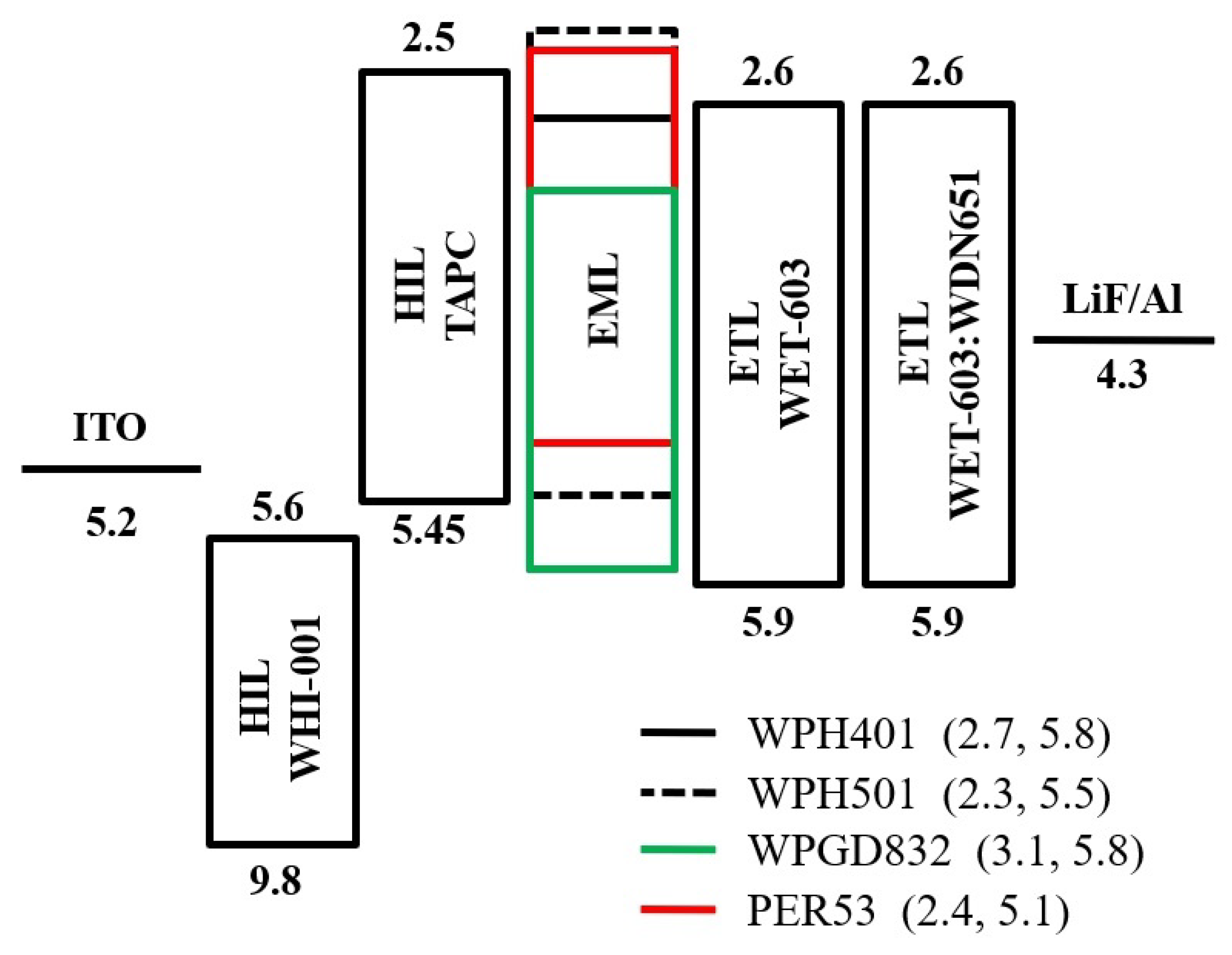
Figure 1 shows schematic illustrations of the blue-hazard-free OLEDs with typical and tandem structures. Figure 2 shows energy level diagram of typical tandem structure. The typical device is composed of a 150 nm indium tin oxide (ITO) layer, a 30 nm WHI-001 hole-injection layer (HIL), a 70 nm WHT-215 hole transporting layer (HTL), a 30 nm emissive layer (EML), a 10 nm WET-603 electron transporting layer (ETL), a 20 nm WET-603:WDN-651 N-doped ETL, a 1 nm lithium fluoride (LiF) layer, and a 150 nm aluminum layer. The emissive layer consists of a WPH-401 host with a 33 wt% WPH-501 co-host doped with a 10 wt% WPGD-832 green emitter and 0.8 wt% PER 53 red emitter. While the tandem device is composed of two emitting units which are connected by charge generation layers, each emitting unit contains a 70 nm WHT-215 HTL, a 30 nm EML, and a 10 nm WET-603 ETL, and the charge generation layers are composed of a 20 nm N-doped ETL, a 2 nm WDN-651 EIL, a 1.5 nm aluminum layer, and a 30 nm WHI-001 HIL. All of the organic and metal layers were deposited under base pressure of 10−6 Torr onto pre-cleaned and oxygen plasma pre-treated ITO glass by using thermal evaporation.

3.2. Encapsulation

After all the layers were deposited, the device was encapsulated to prevent moisture and oxygen from deteriorating the sensitive organic layers. The encapsulation was performed by generating a continuous epoxy lining along the periphery of the emissive area, and then a glass was capped lid on. The whole process was done under low moisture and oxygen condition. The encapsulated device was thereafter treated with UV-light for curing.

3.3. Device Characterization

The current-voltage (I–V) characteristics of the resultant devices were measured using a Keithley 2400 electrometer with Minolta CS-100A luminance-meter. The spectrum, luminance, and CIE chromatic coordinates of all the devices were measured by using a Photo Research PR-655 spectrascan spectroradiometer. All the fabricated devices have an emission area of 9 mm2. All the measurements were done in the forward direction.

3.4. Lifetime Measurement

From the CS-100A, applied current for desired initial luminance is found. Then, the device is kept in the base of a Chroma lifetime test system where the current is set to attain the desired initial brightness. Then, the device is allowed to run under the constant current where the brightness of the device will decrease gradually. The t50 lifetime is measured when the brightness becomes half of its initial value.

4. Results and Discussion

4.1. Device Characteristics

4.1.1. Typical vs. Tandem OLED

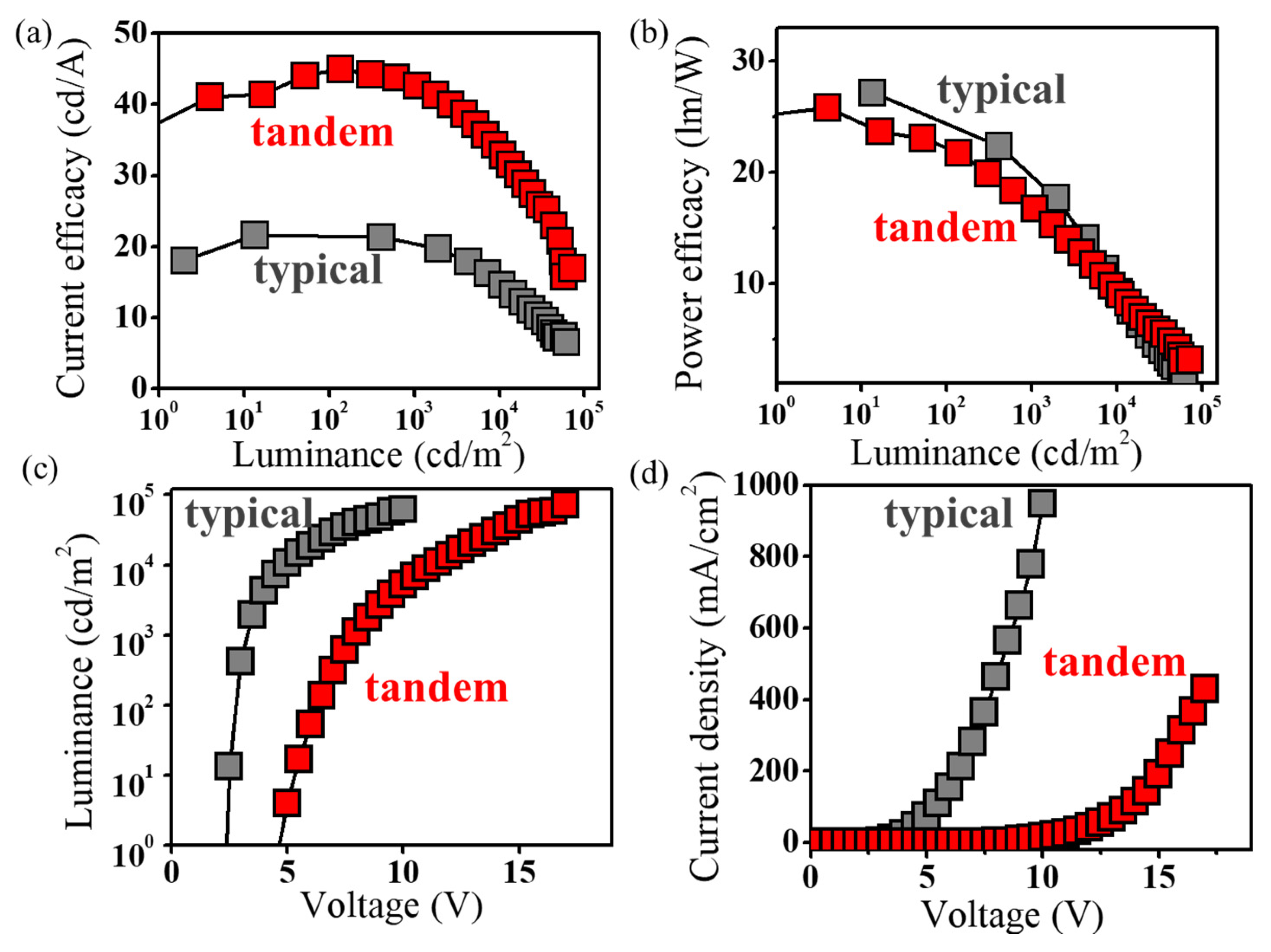
The corresponding electroluminescence performances of both the blue-hazard-free OLED devices are shown in Table 1. Figure 3 shows the comparison of luminance, current density, power efficacy, and current efficacy of the double stacked tandem OLED with that of a typical single electroluminescent unit OLED. Remarkably, the fabricated tandem OLED displayed higher brightness and driving voltage than that of the typical OLED counterpart. For example, maximum brightness of the designed tandem OLED is 1.2 time higher than the typical OLED. Similarly, the driving voltage of double-stack OLED at 100, 1000, and 10,000 cd/m2 is 2.4, 2.4, and 2.3 times higher than that of the single-stack OLED. The reason behind this may be that the much thicker device architecture and designed tandem OLEDs are formed by connecting two single unit OLEDs in series, so the driving voltage and luminance of tandem OLEDs should be equal to the sum of that of individual single unit OLEDs under a certain voltage, as expected in most ideal situation. However, the observed results deviate from the ideal situation, which may be attributed to the produced extra resistance in the designed device structure due to the inefficient electron injection and transportation of in the charge generation layer under bias voltage.
It is also interesting to note that the current efficacy of tandem OLED is more than double in extent than that of the typical device at varying luminance from 100 to 10,000 cd/m2. For example, at 100 cd/m2, the tandem OLED exhibited a current efficacy of 44.6 cd/A, while typical device showed 21.6 cd/A. However, the power efficacy of tandem OLED is slightly lower than the typical device. For example, at 100 cd/m2, the tandem OLED exhibited a power efficacy of 22.3 lm/W; however, 26 lm/W is observed from the typical OLED. Three major reasons may contribute to this. First, tandem device structure reduced the plasmon quenching effect from electrodes because it occurs only at the nearby electrode since the other electrode is too far away. Firstly, the plasmon quenching effect from electrodes is weakened by two single units as plasmon quenching occurs only at the nearby electrode since the other electrode is too far away. Secondly, a high-quality charge carrier unit exists between both the light emitting unit offering equal amounts of holes and electrons under forward bias to improve balance by preventing an excess of charges that would be lost during OLED operation. Hence, the overall carrier recombination balance can be realized leading to higher CE and EQE. Thirdly, the electric-field-induced quenching effect, remarkable in phosphorescent OLEDs, can be restrained. Triplet-triplet annihilation (TTA), triplet-polaron quenching (TPQ), and field-induced quenching are possible quenching processes commonly in PhOLEDs. In our designed OLED with UEML, although the emitting layer is very thin, the relatively high roll-off at the high current density could be TTA due to the short distances among the emitting molecules in the non-doped layer.
It may be because of interface resistance between the stacked organic layers in the tandem architecture. Additionally, the tandem device showed higher driving voltages as compared to the typical OLED because of its much thicker tandem architecture.
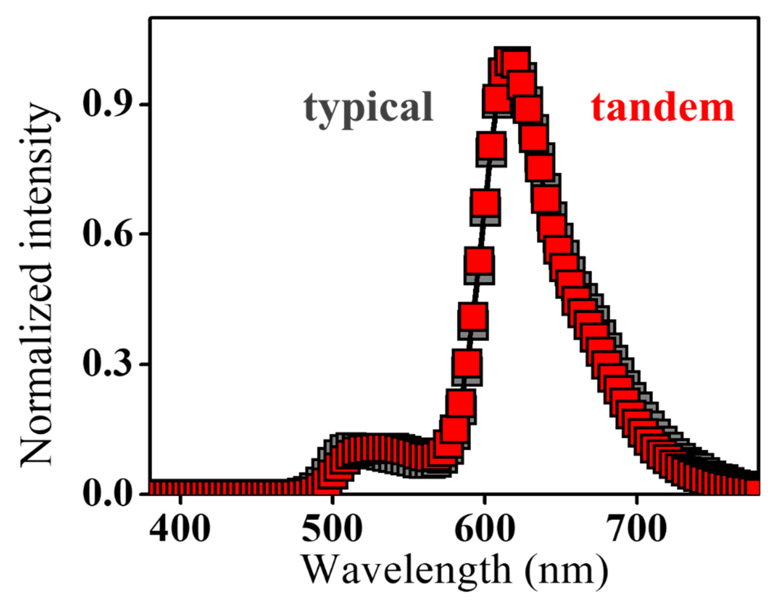
The electroluminescent spectra of both the OLED devices are nearly similar with a major peaking at 610 nm, as shown in Figure 4.
The tandem OLED showed a current efficacy of 33.5 cd/A and an EQE of 22.4% at 10,000 cd/m2 with a maximum luminance of 72,500 cd/m2. It may be because of more balanced charge carrier injection to the stacked electroluminescent units than those in the typical device.

4.1.2. Doping Concentration Effect

Further, the effect of doping concentration of the red emitter has been studied in the tandem OLED, as shown in Table 2. On decreasing the doping concentration of the red dopant from 1 wt.% to 0.8 wt.%, the resulting device showed slightly decreased efficiencies. For example, at a luminance of 100 cd/m2, the resultant device exhibited a power efficacy of 21.3 lm/W, a current efficacy of 37.6 cd/A, and an EQE of 22%. At high brightness, for example, 10,000 cd/m2, the device exhibited an 8.8 lm/W power efficacy, a 29.5 cd/A current efficacy, and a 17.6% EQE. Additionally, the tandem OLED device with 0.8 wt% red emitter exhibited a slight rise in color temperature from 1500 K to 1600 K with a CIE (0.58, 0.40). It should be noted that the light quality of the device still lies in high light-quality range, i.e., CRI and SRI > 75.
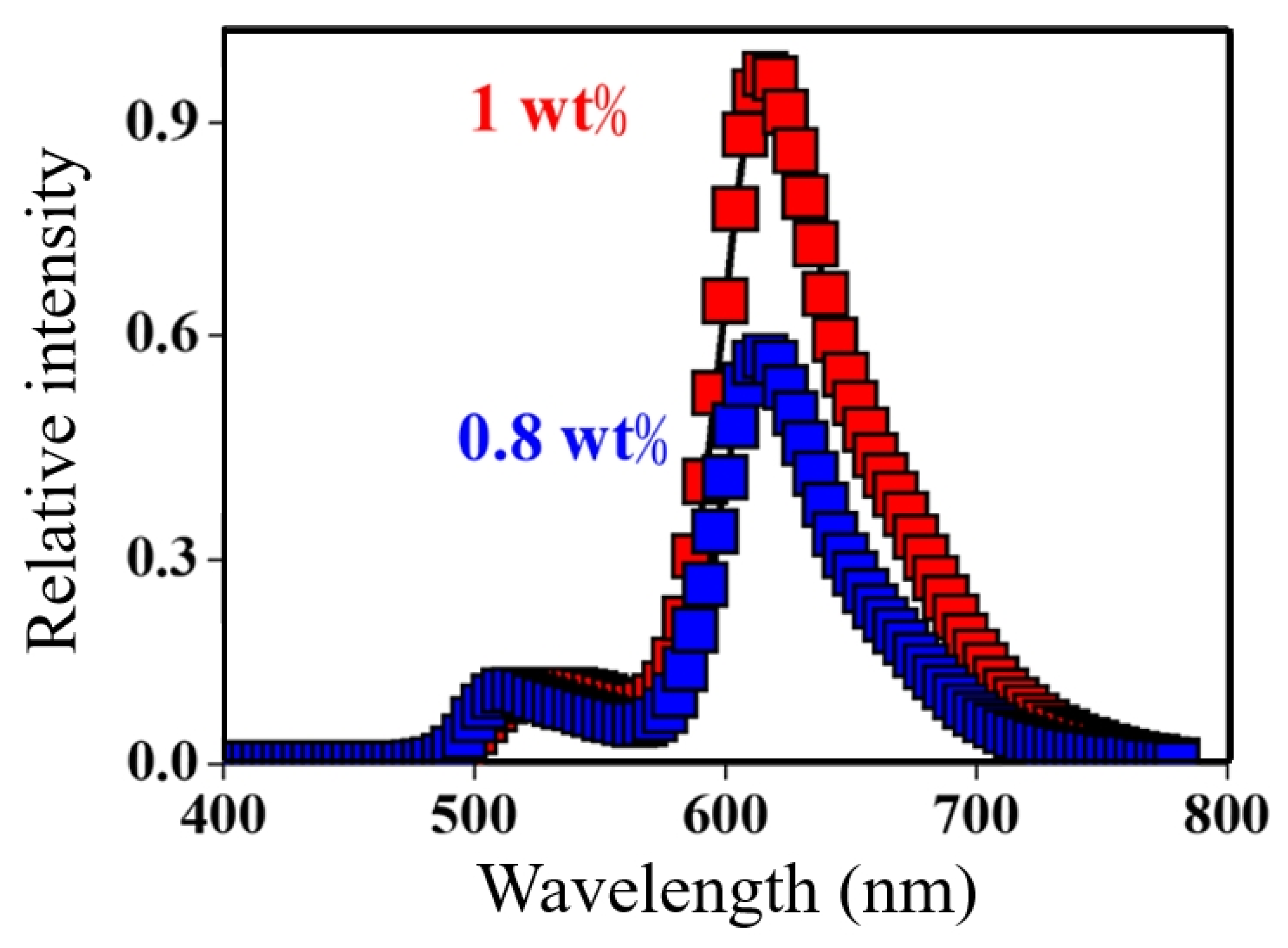
In addition to light quality, emission spectrum of the device has also been characterized in terms of MPE and MSS to ensure the human-eye and -physiology friendliness of the emission. The respective data of both the devices are shown in Table 2. There is no such noticeable variation in MSS values, and both devices suppress 2% melatonin secretion with respect to the reference blue light of 480 nm. It can be explained by considering the electroluminescent (EL) spectra of both the OLED devices, as shown in Figure 5.
As can be seen in Figure 5, the device with a 0.8 wt.% red emitter exhibited a slightly lower intensity emission in long wavelength side (620–720 nm) as compared to the device with 1 wt.% counterpart. Additionally, a significant difference in the MPE values has been observed. At an illuminance of 100 lx, the device with 1 wt.% red emitter showed a 15,403 s (4.3 h) MPE which further decreases to 9595 s (2.6 h) upon decreasing the doping concentration to 0.8 wt.%. It shows that the fabricated blue-hazard-free tandem OLED devices exhibited human eye-friendly lighting which can be used for continuous source of light from 2–4 h without any damage to retina cells.

4.1.3. Emissive Layer Thickness Effect

Further, the initial thickness of the emissive layers was increased from 25 nm to 30 nm in the tandem architecture with 0.8 wt.% red dopant. The device performance decreased slightly in terms of power efficacy, current efficacy, and EQE, as shown in Table 2. However, color coordinates, light-quality, i.e., CRI and SRI >75, MPE, and MSS values remain unchanged. It shows the stability of emission spectrum of the fabricated devices.

4.1.4. OLED Material Purity Effect

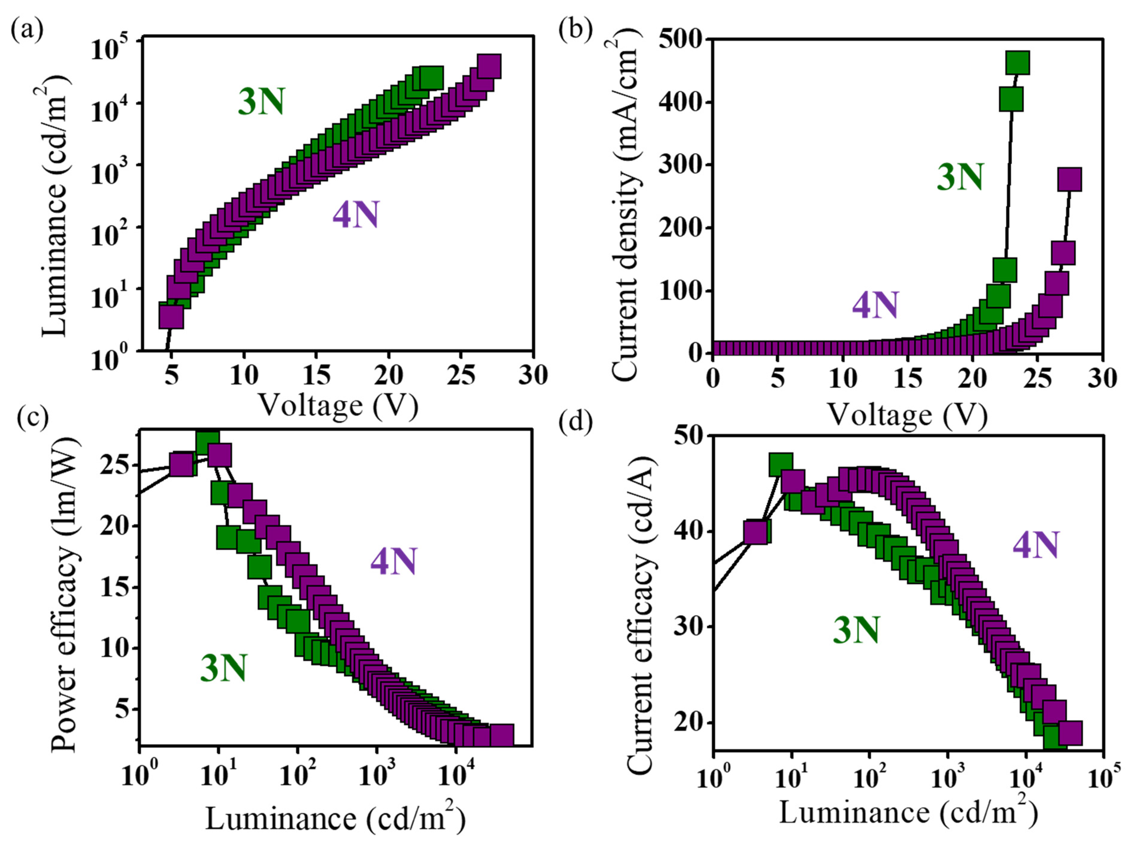
Organic electronic devices are highly sensitive to the purity of the organic materials used. Hence, we have studied the effect of purity level of an emitter on the device characteristics, as shown in Figure 6.
The higher-purity, emitter-based OLED showed a slightly lower operation voltage. The tandem OLED with a green dye of 4N purity exhibited higher efficiencies than those of the 3N purity counterpart. For example, at 100 cd/m2, a power efficacy of 16.8 lm/W, a current efficacy of 45.4 cd/A, and an EQE of 27.6% are observed in the 4N purity-based tandem OLED. On the other hand, the 3N purity-based device exhibited a power efficacy of 11.8 lm/W, a current efficacy of 35.7 cd/A, and an EQE of 21.2%. As shown in Table 2, the tandem OLED with the 4N purity green emitter showed a CRI of 80 and an SRI of 78 at 1000 cd/m2. Regardless, the emitter purity of both blue-hazard-free OLED devices suppresses melatonin secretion by around 1.7 ± 0.2% which is much lower than that of the high-color-temperature, cold-white lighting sources. In other words, the cold-white compact fluorescent bulb (CT 5921 K, MSS 29%), cold-white light emitting diode (CT 5501 K, MSS 20%), and cold-white OLED (CT 5000 K, MSS 12%) are 16.1-, 10.8-, and 6.1-fold more hazardous to the generation of melatonin than the two fabricated blue-hazard-free OLED counterparts.

4.2. Device Lifetime

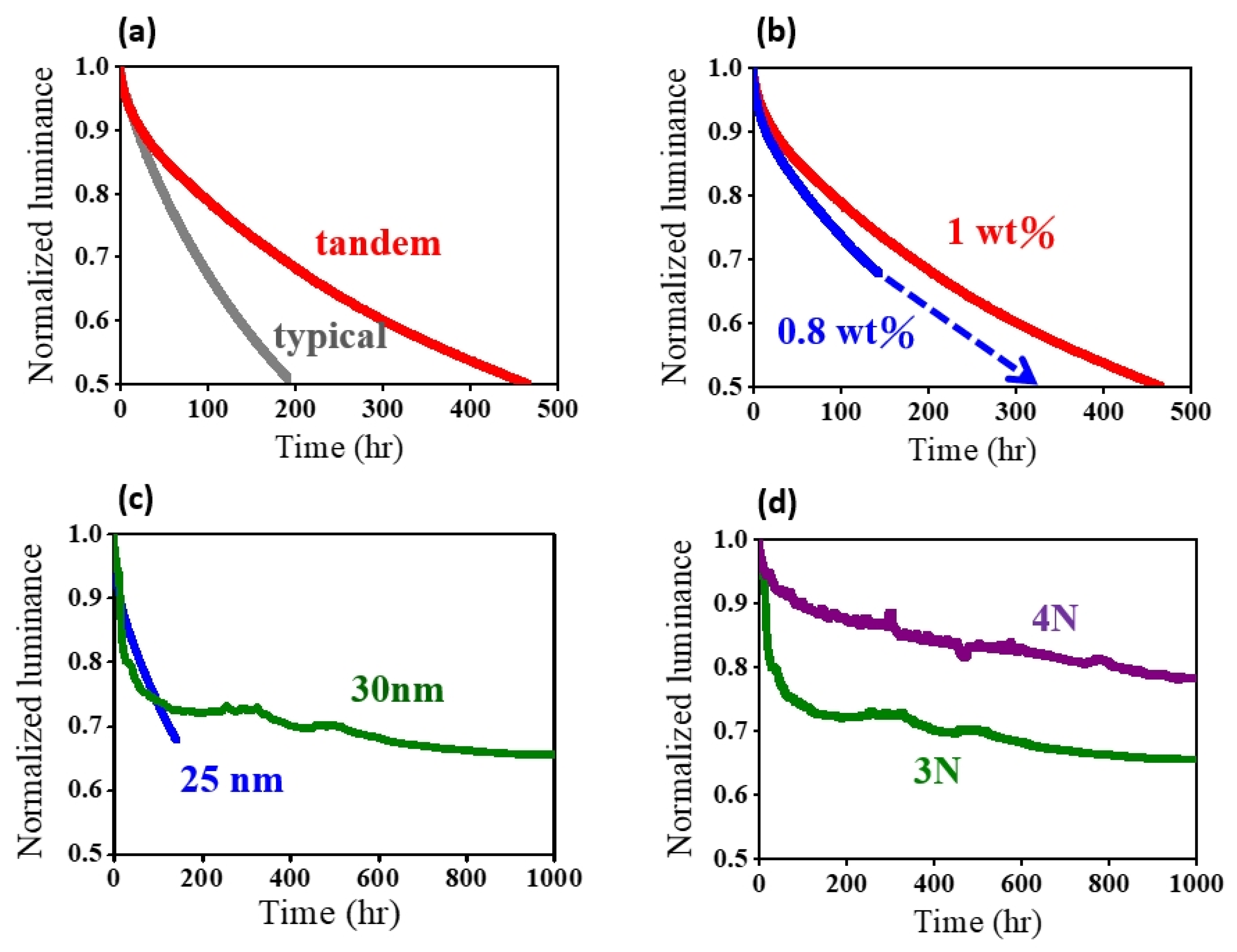
The device operational stability in terms of normalized luminance against operative time of the fabricated OLEDs is shown in Figure 7. A typical single stack OLED device exhibited a lifetime of 10,000 h under the application of a constant current with an initial luminance of 10,000 cd/m2. On the other hand, the fabricated double stacked tandem OLED showed a lifetime of 23,382 h. It is more than double in extent with that of the typical OLED at 50% decay of the initial luminance, as shown in Figure 7a. A tandem OLED with a reduced doping concentration of red emitter exhibited a lifetime of 16,037 h. As shown in Figure 7b, the plot of the 70% decay of the initial luminance of 10,000 cd/m2 is extrapolated up to 50% of its decay. Further, by increasing the thickness of the emissive layer from 25 to 30 nm, the resulting OLED showed a drastic change in the device lifetime, as can be seen in Figure 7c. By extrapolating the plot of lifetime up to 50% decrement in the initial brightness of 10,000 cd/m2, the OLED device exhibited a long lifetime of 223,500 h. A slightly thick emissive layer structure facilitates the carrier recombination at high current density without degradation in the organic layers and results in substantial improvement in the lifetime of the device. The purity of organic materials is crucial for the device stability. It controls self-heating of organic films caused by joule heating at high luminance and consequently inhibits the degradation mechanisms inside the device. As shown in Figure 7d, the device with the high purity 4N emitter showed a sharp fall in lifetime until the 95% decrement of initial luminance of 10,000 cd/m2 which later decreases steadily. However, the device with 3N purity exhibited a sharp fall until 80% decay of initial luminance, and the luminance further decreases unsteadily till 70% of its decay, representing accelerated degradation mechanisms at high luminance. The fabricated tandem OLED with 4N purity emitter showed a lifetime (t50) longer than 223,500 h, which is highest among all the reported long lifetime tandem OLEDs to date.

5. Conclusions

In conclusion, we have fabricated a long-lifetime, blue-hazard-free OLED by using tandem device architecture. The resultant OLED exhibited a long operation time, i.e., more than 223,500 h at 1000 cd/m2. The high-purity, organic emitter provides enough stability to achieve a long device lifetime. Notably, the OLED device showed a color temperature (1600 K) much lower than that of candles (1800 K) and also exhibited high light-quality emission with a CRI of 80 and an SRI of 78. This high light-quality, blue-hazard-free OLED can be recommended as the safest lighting measure for indoor lighting after dusk. At an applied illuminance of 100 lx, the general brightness for indoor lighting, the resultant device showed a longer eye exposure duration of 12,306 s without any damage to retina cells. Additionally, it suppresses only 1.7% of melatonin secretion, lower than that of candlelight. The fabricated OLED fulfills all the needed criteria of human-friendly lighting for commercialization with a sufficiently long lifetime.

Author Contributions

Conceptualization, J.-H.J. and W.-J.L.; methodology, J.-H.J.; validation, W.-J.L., S.-H.S. and S.S.; formal analysis, W.-J.L. and S.-H.S.; investigation, W.-J.L.; resources, Y.-C.T. and S.-W.W.; data curation, W.-J.L.; writing—original draft preparation, M.S. and S.S.; writing—review and editing, Y.-S.W.; visualization, Y.-S.W.; supervision, J.-H.J.; project administration, J.-H.J. All authors have read and agreed to the published version of the manuscript.

Funding

This research was funded by Ministry of Science and Technology through grant MOST 106-2119-M-007-011.

Data Availability Statement

The data presented in this study are available on request from the corresponding author.

Acknowledgments

The authors are thankful for the financial support in part by Ministry of Science and Technology through grant MOST 106-2119-M-007-011.

Conflicts of Interest

The authors declare no conflict of interest.

References

  1. Reineke, S.; Lindner, F.; Schwartz, G.; Seidler, N.; Walzer, K.; Lüssem, B.; Leo, K. White organic light-emitting diodes with fluorescent tube efficiency. Nature 2009, 459, 234–238. [Google Scholar] [CrossRef] [PubMed]
  2. Seino, Y.; Inomata, S.; Sasabe, H.; Pu, Y.J.; Kido, J. High-Performance Green OLEDs Using Thermally Activated Delayed Fluorescence with a Power Efficiency of over 100 lm W−1. Adv. Mater. 2016, 28, 2638–2643. [Google Scholar] [CrossRef] [PubMed]
  3. Jou, J.-H.; Tang, M.-C.; Chen, P.-C.; Wang, Y.-S.; Shen, S.-M.; Chen, B.-R.; Lin, C.-H.; Wang, W.-B.; Chen, S.-H.; Chen, C.-T.; et al. Organic light-emitting diode-based plausibly physiologically-friendly low color-temperature night light. Org. Electron. 2012, 13, 1349–1355. [Google Scholar] [CrossRef]
  4. Jou, J.H.; Wu, M.H.; Shen, S.M.; Wang, H.C.; Chen, S.Z.; Chen, S.H.; Lin, C.R.; Hsieh, Y.L. Sunlight-style color-temperature tunable organic light-emitting diode. Appl. Phys. Lett. 2009, 95, 10–13. [Google Scholar] [CrossRef]
  5. Nicolai, H.T.; Hof, A.; Blom, P.W.M. Device Physics of White Polymer Light-Emitting Diodes. Adv. Funct. Mater. 2012, 22, 2040–2047. [Google Scholar] [CrossRef]
  6. Srećko, K.; Šego, Z. OLED technology and displays. In Proceedings of the ELMAR-2012, Zadar, Croatia, 12–14 September 2012. [Google Scholar]
  7. Kim, J.-J.; Han, M.-K.; Noh, Y.-Y. Flexible OLEDs and organic electronics. Semicond. Sci. Technol. 2011, 26, 30301. [Google Scholar] [CrossRef]
  8. Li, Y.; Tan, L.W.; Hao, X.T.; Ong, K.S.; Zhu, F.; Hung, L.S. Flexible top-emitting electroluminescent devices on polyethylene terephthalate substrates. Appl. Phys. Lett. 2005, 86, 1–3. [Google Scholar] [CrossRef]
  9. Jou, J.H.; Chou, K.Y.; Yang, F.C.; Hsieh, C.H.; Kumar, S.; Agrawal, A.; Chen, S.Z.; Li, T.H.; Yu, H.H. Pseudo-natural light for display and lighting. Adv. Opt. Mater. 2015, 3, 95–102. [Google Scholar] [CrossRef]
  10. Xie, Z.Y.; Hung, L.S. High-contrast organic light-emitting diodes. Appl. Phys. Lett. 2004, 84, 1207–1209. [Google Scholar] [CrossRef]
  11. Ichikawa, M.; Amagai, J.; Horiba, Y.; Koyama, T.; Taniguchi, Y.J. Dynamic turn-on behavior of organic light-emitting devices with different work function cathode metals under fast pulse excitation. Appl. Phys. 2003, 94, 7796–7800. [Google Scholar] [CrossRef]
  12. Williams, T.P. Photoreversal of Rhodopsin Bleaching. J. Gen. Physiol. 1964, 47, 679–689. [Google Scholar] [CrossRef] [PubMed]
  13. Kuse, Y.; Ogawa, K.; Tsuruma, K.; Shimazawa, M.; Hara, H. Damage of photoreceptor-derived cells in culture induced by light emitting diode-derived blue light. Sci. Rep. 2014, 4, 1–12. [Google Scholar] [CrossRef] [PubMed]
  14. Pauley, S.M. Lighting for the human circadian clock: Recent research indicates that lighting has become a public health issue. Med. Hypotheses 2004, 63, 588–596. [Google Scholar] [CrossRef] [PubMed]
  15. Arendt, J.N. Melatonin, circadian rhythms, and sleep. N. Engl. J. Med. 2000, 343, 1113–1116. [Google Scholar] [CrossRef] [PubMed]
  16. Stevens, R.G.; Brainard, G.C.; Blask, D.E.; Lockley, S.W.; Motta, M.E. Breast cancer and circadian disruption from electric lighting in the modern world. CA Cancer J. Clin. 2014, 64, 207–218. [Google Scholar] [CrossRef]
  17. Light Pollution Effects on Wildlife and Ecosystem, International Dark-Sky Association. Available online: http://darksky.org/light-pollution/wildlife/ (accessed on 1 January 2022).
  18. Jou, J.-H.; Chen, S.-H.; Shen, S.-M.; Jou, Y.-C.; Lin, C.-H.; Peng, S.-H.; Hsia, S.-P.; Wang, C.-W.; Chen, C.-C.; Wang, C.-C. High efficiency low color-temperature organic light-emitting diodes with a blend interlayer. J. Mater. Chem. 2011, 21, 17850. [Google Scholar] [CrossRef]
  19. Jou, J.H.; Hsieh, C.Y.; Tseng, J.R.; Peng, S.H.; Jou, Y.C.; Hong, J.H.; Shen, S.M.; Tang, M.C.; Chen, P.C.; Lin, C.H. Candle light-style organic light-emitting diodes. Adv. Funct. Mater. 2013, 23, 2750–2757. [Google Scholar] [CrossRef]
  20. Hu, Y.; Zhang, T.; Chen, J.; Ma, D.; Cheng, C.H. Hybrid Organic Light-Emitting Diodes with Low Color-Temperature and High Efficiency for Physiologically- Friendly Night Illumination. Isr. J. Chem. 2014, 54, 979–985. [Google Scholar] [CrossRef]
  21. Li, W.; Sun, C.; Yang, L.; Zhu, W.; Zhang, H.; Cai, M.; Zhang, X.; Wei, B. Extremely low color-temperature white organic electroluminescence devices based on the control of exciton recombination zone. Phys. Status Solidi Appl. Mater. Sci. 2016, 213, 2400–2405. [Google Scholar] [CrossRef]
  22. Sun, Q.; Hu, Y.; Dai, Y.; Ma, D.J. Low color-temperature, high color rendering index hybrid white organic light-emitting diodes by the effective control of exciton recombination zone. Mater. Chem. C 2017, 5, 8022–8026. [Google Scholar] [CrossRef]
  23. Panasonic Developed a 114 lm/W OLED Panel—Claims World’s Most Efficient Panel. Available online: https://www.oled-info.com/taxonomy/term/129/all?page=4 (accessed on 1 January 2022).
  24. Liu, B.; Wang, L.; Xu, M.; Tao, H.; Zou, J.; Gao, D.; Lan, L.; Ning, H.; Peng, J.; Cao, Y. Efficient hybrid white organic light-emitting diodes with extremely long lifetime: The effect of n-type interlayer. Sci. Rep. 2014, 4, 1–5. [Google Scholar] [CrossRef] [PubMed]
  25. WHY OLED? Sunoptics. Available online: http://sunoptics.acuitybrands.com/sitecore/content/acuitybrandscorporate/home/oled/why-oled (accessed on 1 January 2022).
  26. LG Chem Launches the World’s Largest OLED Lighting Panel at 320 × 320 mm. Available online: https://www.oled-info.com/lg-chem-launches-worlds-largest-oled-lighting-panel-320x320-mm (accessed on 1 January 2022).
  27. Miller, N.J.; Leon, F.A. OLED Lighting Products: Capabilities, Challenges, Potential; Pacific Northwest National Lab. (PNNL): Richland, WA, USA, 2016.
  28. Yeolight Developed New Amber OLED Lighting and Automotive OLED Rearlights. Available online: https://www.oled-info.com/yeolight-developed-new-oled-panels-and-automotive-oled-rearlights (accessed on 1 January 2022).
  29. Jou, J.H. Melatonin Suppression Extent Measuring Device. U.S. Patent S20120303282 A1, 19 August 2012. [Google Scholar]
  30. International Commission on Non-Ionizing Radiation Protection. Guidelines on limits of exposure to ultraviolet radiation of wavelengths between 180 nm and 400 nm (incoherent optical radiation). Health Phys. 2004, 87, 171–186. [Google Scholar] [CrossRef] [PubMed]
  31. Jou, J.H.; Chou, K.Y.; Yang, F.C.; Agrawal, A.; Chen, S.Z.; Tseng, J.R.; Lin, C.C.; Chen, P.W.; Wong, K.T.; Chi, Y. A universal, easy-to-apply light-quality index based on natural light spectrum resemblance. Appl. Phys. Lett. 2014, 104, 203304. [Google Scholar] [CrossRef]
  32. Scholz, S.; Kondakov, D.; Lüssem, B.; Leo, K. Degradation Mechanisms and Reactions in Organic Light-Emitting Devices. Chem. Rev. 2015, 115, 8449–8503. [Google Scholar] [CrossRef]
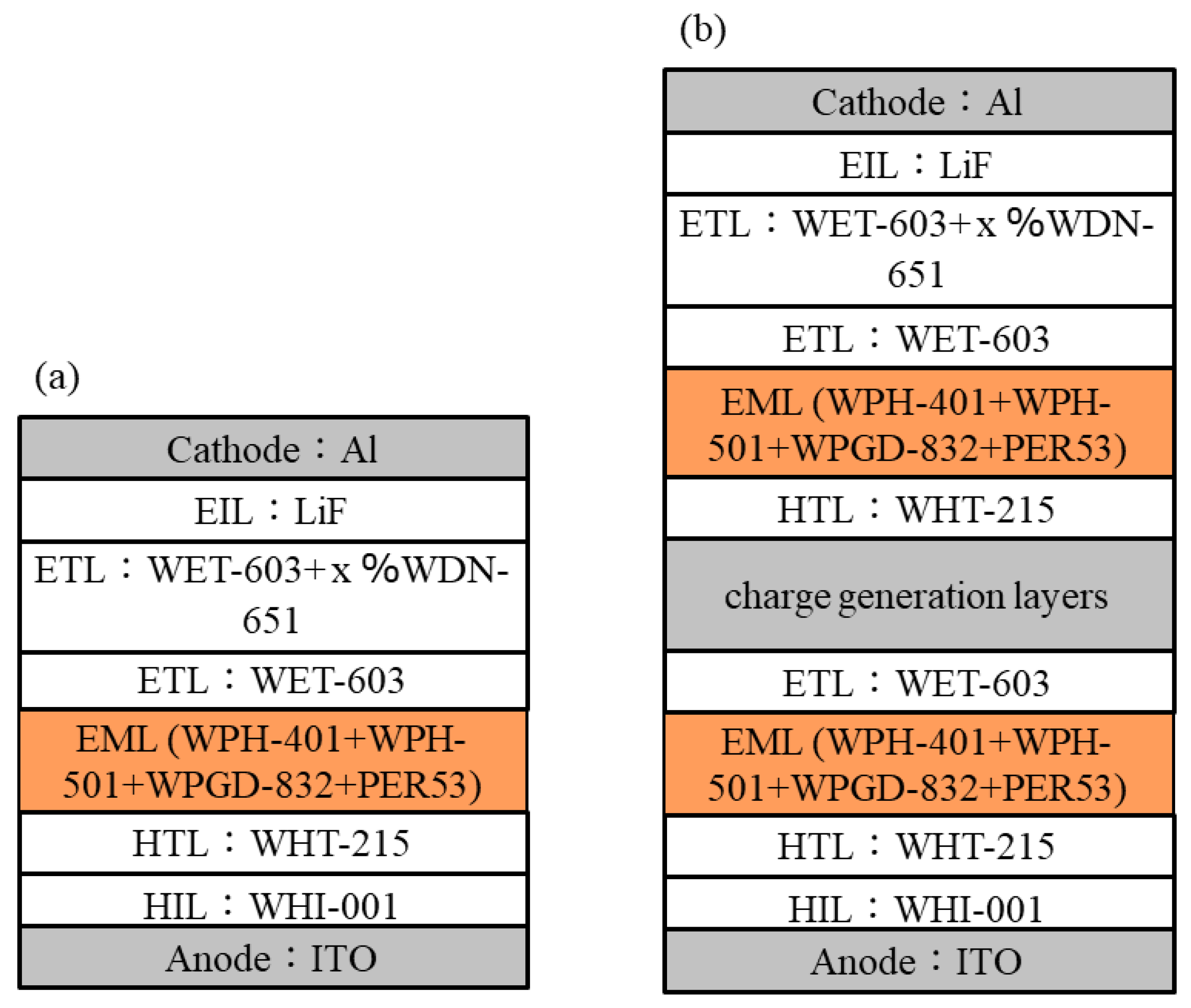
Figure 1. Schematic illustrations of the blue-hazard-free OLEDs with (a) typical and (b) tandem structures.
Electronics 12 02099 g001
Figure 2. Energy level diagram of typical tandem structure.
Electronics 12 02099 g002
Figure 3. Comparison of the (a) current efficacy, (b) power efficacy, (c) luminance, and (d) current density characteristics of the studied blue hazard free OLEDs with typical and tandem structures.
Electronics 12 02099 g003
Figure 4. EL spectra of the studied blue hazard free OLEDs with typical and tandem structures at 1000 cd/m2.
Electronics 12 02099 g004
Figure 5. Effect of red dopant concentration on the EL spectra and color temperature of the resultant blue hazard free tandem OLEDs at 1000 cd/m2.
Electronics 12 02099 g005
Figure 6. Effect of green dye purity on (a) luminance, (b) current density, (c) power efficacy, and (d) current efficacy of the tandem OLEDs.
Electronics 12 02099 g006
Figure 7. Effect of (a) device architecture, (b) doping concentration of red dye, (c) emissive layer thickness, and (d) green dye purity on the lifetime of the blue hazard free tandem OLEDs driven under constant current with an initial brightness of 10,000 cd/m2.
Electronics 12 02099 g007
Table 1. Effect of device architecture on the operation voltage (OV), power efficacy (PE), current efficacy (CE), external quantum efficiency (EQE), CIE color coordinates, maximum luminance, and lifetime of the studied blue hazard free OLEDs.
Device
Architecture
Doping
Concentration (wt%)
OV [V]PE [lm/W]CE [cd/A]EQE [%]CIE (x, y)
Chromatic
Coordinates
Max
Luminance
(cd/m2)
Lifetime
(h)
@ 1000
cd/m2
@ 100/1000/10,000 cd/m2
Typical1 wt%2.6/
3.2/
4.9
26.1/
20.5/
9.6
21.6/
20.7/
14.9
14.7/
14.9/
10.5
(0.60, 0.38)/
(0.62, 0.38)/
(0.61, 0.38)/
61,00010,000
Tandem1 wt%6.3/
7.9/
11.3
22.3/
17.0/
9.3
44.6/
42.8/
33.5
28.9/
28.6/
22.4
(0.61, 0.39)/
(0.61, 0.38)/
(0.61, 0.38)/
72,50023,382
Table 2. Effect of doping concentration, emissive layer thickness and purity of green dye on the OV, PE, CE, EQE, CIE coordinates, CRI, SRI, maximum permissible exposure-limit (MPE), melatonin suppression sensitivity (MSS), and lifetime (t50) of the blue-hazard-free tandem OLEDs studied.
Doping
Concentration (wt%)
Emissive
Layer
Thickness
(nm)
Purity
of
Green Dye
OV [V]PE [lm/W]CE [cd/A]EQE [%]CIE (x, y)
Chromatic
Coordinates
CRISRIMPE
(s)
MSS
(%)
Lifetime
(h)
@ 1000
cd/m2
@ 100/1000/10,000 cd/m2
1253N6.3/
7.9/
11.3
22.3/
17.0/
9.3
44.6/
42.8/
33.5
28.9/
28.6/
22.4
(0.61, 0.39)/
(0.61, 0.38)/
(0.61, 0.39)/
85/
84/
85
76/
75/
77
14,969/
15,403/
14,862
1.6/
1.5/
1.5
23,382
0.8253N5.6/
7.2/
10.5
21.3/
16.7/
8.8
37.6/
38.1/
29.5
22.0/
22.7/
17.6
(0.58, 0.40)/
(0.59, 0.40)/
(0.58, 0.40)/
75/
75/
76
77/
76/
77
8,783/
9,595/
8,817
2.1/
2.0/
2.1
16,037
0.8303N9.4/
14.3/
20.5
11.8/
7.5/
3.7
35.7/
34.0/
23.9
21.2/
20.9/
14.8
(0.59, 0.40)/
(0.59, 0.40)/
(0.58, 0.41)/
78/
77/
76
77/
78/
79
10,802/
10,106/
7,685
1.9/
2.0/
2.3
223,500
0.8304N8.5/
15.6/
24.7
16.8/
7.5/
3.2
45.5/
37.4/
24.8
27.6/
22.7/
14.9
(0.60, 0.39)/
(0.59, 0.40)/
(0.57, 0.41)/
80/
80/
80
77/
78/
78
12,306/
11,025/
10,708
1.7/
1.8/
1.8
>223,500
Disclaimer/Publisher’s Note: The statements, opinions and data contained in all publications are solely those of the individual author(s) and contributor(s) and not of MDPI and/or the editor(s). MDPI and/or the editor(s) disclaim responsibility for any injury to people or property resulting from any ideas, methods, instructions or products referred to in the content.