Review

A Review–Unguided Optical Communications: Developments, Technology Evolution, and Challenges

1
Free Space Optical Communication Laboratory, Defence Institute of Advanced Technology, Pune 411025, India
2
Electronics and Communication Engineering, National Institute of Technology Karnataka, Mangalore 575025, India
3
Department of Informatics, Faculty of Information and Communications Technology, Universitas Nasional, Jakarta 12520, Indonesia
4
Department of E-Learning Center, Universitas Siber Asia, Jakarta 12550, Indonesia
5
École de Technologie Supérieure (ÉTS), Université du Québec, Montréal, QC H3C 1K3, Canada
6
Cyber Security Systems and Applied AI Research Center, Lebanese American University, Byblos P.O. Box 36, Lebanon
7
Optical Communications Research Group, Northumbria University, Newcastle NE1 8ST, UK
8
Department of Physics, Colorado State University, Pueblo, CO 81001, USA
9
Department of Engineering, Faculty of Science and Engineering, Manchester Metropolitan University, Manchester M1 5GD, UK
*
Authors to whom correspondence should be addressed.
Electronics 2023, 12(8), 1922; https://doi.org/10.3390/electronics12081922
Submission received: 6 February 2023 / Revised: 19 March 2023 / Accepted: 29 March 2023 / Published: 19 April 2023
(This article belongs to the Special Issue New Technologies in Visible Light Communications)

Abstract

:
This review paper discusses the complete evolution of free-space optical (FSO) communication, also known as unguided optical communication (UOC) technologies, all the way back to ancient man’s fire to today’s machine-learning-supported UOC systems. The principles, significance, and developments that have happened over the past several decades, as well as installation methodologies, technological limitations, and today’s challenges of UOCs are presented. All the subsets of UOC: FSO communication, underwater optical wireless communication (UOWC), and visible light communication (VLC), with their technology/system developments, potential applications, and limitations are reviewed. The state-of-the-art developments/achievements in (i) FSO channel effects and their mitigation techniques; (ii) radio-over-FSO techniques; (iii) wavelength division multiplexing and sub-carrier multiplexing techniques; (iv) FSO for worldwide interoperability for microwave access applications; (v) space optical satellite communication (SOSC); (vi) UWOC; (vii) photoacoustic communication (PAC); (viii) light-fidelity; (ix) VLC; (x) vehicular VLC (V2LC); and (xi) optical camera communication are reviewed. In addition, the current developments on emerging technologies such as artificial intelligence (to improve the performance of UOC systems), energy harvesting (for the effective utilization of UOC channels), and near-future communication network scenarios (mandatory for secured broadband digital links) are covered. Finally, in brief, to achieve the full potential of UOC systems, challenges that require immediate research attention are summarized.

1. Introduction to Unguided Optical Communication (UOC)

1.1. Revolution of UOC

This review paper covers the evaluation of today’s free-space optical (FSO) communication, also known as unguided optical communication (UOC), and their techniques/systems, right from prehistoric fire-based signal transmission. The technology developments in the field of UOC have significantly evolved over the past several decades, which has led, in depth, to FSO communications, underwater optical wireless communications (UOWC), and optical wireless communications (OWC). Though, primarily, these transmission schemes have a common denominator in their transceiver chains, they require different kinds of installation mechanisms, beam processing, optoelectronic and electro-optic components, signal processing, and performance indicators, due to differences in data link range, transmission medium, and applications. Due to its dual nature, light does not need any medium to travel. However, due to channel effects, in FSO systems, the link range is long, typically in the order of several kilometers, while in UOWC and OWC systems, the link span is relatively short, typically in the order of a few meters. Optical wireless technologies catering for low to high data rates are being used in a range of applications for last-meter/last-mile access networks, terrestrial long-range connectivity, ground to air/space links, air-to-water/underwater networks, and fifth-generation (5G)/emerging 6G wireless networks, etc. [1,2]. This review paper covers a broad spectrum of developments, breakthroughs, and achievements in the field of UOC techniques, starting from their origin through to today’s successful artificial intelligence (AI)-supported UOC systems. The developments in optoelectronics components and optical/electrical signal processing platforms/algorithms, which are advancing the UOC techniques aiming to resolve near-future data traffic, are presented [2]. UOC systems were initially designed for only point-to-point simplex data communication and later duplex data communications, and then for full-duplex transmission [3]. With advances made in making optical sources and detectors, optoelectronic devices, wavelength selection devices, and modulation/coding techniques, UOC systems operating under weather conditions have remarkably improved [4,5], thus making them attractive for a variety of purposes. These include indoor, in-flight, underwater, and vehicular communication, as well as communications from the surface to unmanned aerial vehicles (UAVs), inter-satellite communications, etc. [6,7,8]. Considering the growing number of applications of these systems, it is important to address the challenges in UOC to ensure their full utilization. These challenges include the estimation/prediction of channel effects, accurate measurement of the received optical beam’s temporal/spatial disturbances, development of optimum mitigation schemes, reliability analysis/prediction of system parameters, efficient transmission of radio over FSO links, design of hybrid FSO–radio frequency (RF) antennas, finding tunable modulation techniques, framing implementations and installations strategies, incorporating AI techniques, efficient UOC channel energy harvesting, designing the next generation of UOC network architecture, using UOC in the Internet of Things (IoT) as a part of 5G/6G wireless networks, etc. [5,6,7,8,9]. Note that, at the research level, only a few of the above challenges have been addressed. To address these challenges, one of the best options would be the integration of several allied research fields such as the design of high phase stable optical sources, high-data-rate modulation/demodulation optoelectronics devices, high-speed signal/data processing, AI-based optimization, design of mid-infrared/quantum-cascaded lasers, design of long-wave infrared optical sources, quantum encoding/decoding schemes, intelligent energy harvesting techniques, high-data rate optical detectors, etc. [8,9,10,11]. However, addressing all these research barriers is of the utmost importance to build a network infrastructure capable of handling near-future data traffic. Therefore, a comprehensive review of these challenges together, from their initial status to today’s mature and the state of art developments, is essential to allow the readers to comprehend them. Several review/review papers addressing focused (very narrow) and limited issues on sub-topics of UOC technology have been reported in the literature [10,11,12,13,14].
Recently published review papers have addressed only a few topics [9,10,11,12,13,14]. However, minimal review works reported on a comprehensive evaluation of UOC systems/techniques, all the way back to ancient man’s fire to present-day AI-supported UOC technology. This coextensive review will benefit many readers considering that near-future high-data-rate wireless networks will benefit from the integration and operation of UOC systems individually and together (combined version) with RF signals. To the best of our knowledge, no review paper covers the entire roadmap of UOC, as in Figure 1.
In this review paper, we cover a thorough investigation on the complete evolution of UOC technologies right from the prehistoric man’s fire-based communications. Brief historical developments of communication technologies and the working principles and installation strategies of UOC systems are covered in Section 1.2 and Section 1.3, respectively. Section 2 reviews FSO communications, channel effects and mitigation techniques. Hybrid FSO–RF systems and the achievements therein are covered in Section 3. Section 4 and Section 5 present optical water communications and wireless optical communications, respectively. Section 6 outlines the recent developments in UOC with AI, and energy harvesting, whereas Section 7 addresses next-generation UOC networks and several associated research challenges. Finally, Section 8 concludes this review paper.

1.2. A Brief History of Communication Technology

Communication technologies have evolved over time, reaching their status and capabilities for use in a multitude of applications in many areas. The capability to cover a huge amount of data information at very high speed with high quality and minimum latency is the main feature of the modern communication technology, which underpins today’s telecommunications services. We have seen a tremendous advance from pre-historic smoke-based pre-coded signal transmission system to the 21st century’s smart mobile phones with a multitude of features and capabilities not seen before [1,15]. Prehistoric man used smoke signs, firelight, and some sound sources to convey pre-defined (coded) messages (i.e., celebrations, war, etc.) over line-of-sight (LoS) and short coverage areas. The terrestrial signal towers used in the Great Wall of China and coastal signal towers in the Mediterranean region demonstrated the use of light (fire)-based communications over longer transmission ranges, which are still being used [16]. Greece invented the hydraulic semaphore in the 4th century before Christ (BC), and also used it during the time of Punic war, which was in the 3rd century BC, for communication purposes. In the 5th century BC, the first network of pigeon messengers is thought to have been established in Assyria and Persia by Cyrus the Great. In 2000 BC, they were carrying messages to warring groups in Mesopotamia. The great Persian Empire of Cyrus in the 6th century BC employed relays of mounted messengers, served by posthouses. The system was favorably described by the Greek historians Herodotus and Xenophon. Following these early developments, the Egyptians, Romans, and Chinese introduced new systems [1,2,3]. In the 18th Century, the French introduced navy communications through flag-holding semaphore, conveying information between ships, which was an advanced version of the systems first introduced by the Romans. In 1672, Robert Hooke demonstrated speech transmission with the help of an acoustic telephone and showed that sound signals could pass through a wire medium. In 1790, after the navy flag messaging system, the Chappe brothers demonstrated an initial optical/light telegraph scheme in Europe. Pendulum-like mechanical arm structures were built on a tower, which were used for the data transfer between towers [3,4]. In 1838, S.B. Morse, V. Alfred, and G. Leonard came up with the idea of a telegraph recording process, where a button-based data transmission scheme was proposed and named as Morse code [4]. In 1858, wired telephonic communications between Britain and the US were demonstrated successfully. A man named Cyrus Field from New York wanted to lay the first transatlantic telephone cable to connect England and the United States by telegraph. This project, though it was met with many setbacks, was finally completed in August of 1858 [3]. In 1867, British Admiral Philip Colomb established a lamp-based code-signaling mechanism for inter-ship communications.
The year 1876 was a significant one for Alexander Graham Bell. Having come to the U.S. as a teacher for the deaf, he had been trying to figure out a way to transmit speech electronically. Despite little support from his friends, he successfully invented the telephone in March of 1876 [3]. In 1877, Thomas Alva Edison demonstrated a phonograph system using an acoustic mechanism for recording sound signals. In the 19th century, A. Graham Bell demonstrated the “photophone,” as shown in Figure 2a, where light beams were used for the transmission of acoustic signals; this was not taken further but set the foundation for wireless transmission using light [16]. In 1893, Nikolai Tesla was able to transmit wireless RF signals successfully. Following that, in 1896, Marconi was successful in transmitting RF signals over a 2 km distance [17]. Alexander Graham Bell was back in the history books again after he made the first coast-to-coast call by phone to his assistant in January of 1915. It was the first long-distance call made in history from a landline. It has significance because it made long-distance communication all over the country a reality [3]. In 1927, the first wireless communication using the telephone was established between England and the USA [5,18]. In 1930, the company named “American Telephone & Telegraph” demonstrated the videophone. In 1934, wireless communications were established between the USA and Japan. In 1936, in Germany, videophone connectivity was used for communal purposes. In 1946, the introduction of a voice mobile phone calling system was demonstrated. In 1956, a telephone link with 36 circuit cables was established between Scotland and Newfoundland. In 1962, the first wireless space satellite communications were demonstrated for the first time. In 1964, George Hockham and Charles Kao verified voice communications using light over fiber-optic cables for the first time. Following the invention of the laser, fundamental and ground-breaking steps were taken in terrestrial long-distance communications [3,19]. The availability of coherent laser sources opened new opportunities for light-based communication. In 1965, the picture phone trial was initiated, while in 1969, the first internet service between a few computers in four universities in the USA under the Advanced Research Projects Internet Advanced Research Projects Agency Network (ARPANET) was demonstrated. Inventor Martin Cooper placed the first cellular mobile call in 1973 to his rival at Bell Labs, Joel Engel. The first mobile phone had a maximum talk time of 30 min, and it took a year for the battery to recharge. The phone would eventually be a prototype for Motorola’s first mobile phones [3,5,6,7]. In 1979, because of the judgment and necessity of INMARSAT, naval boats were connected for security and safety communications. In 1981, Japan deployed a communal automatic mobile network. This was followed by a secured and limited amount of internet data transmission for the emergency services, corporations, and researchers of a few universities in 1982 [5,6].
On 1 January 1983, the Internet was officially born. ARPANET officially switched its old network control protocols and Transmission Control Protocol/Internet Protocol became standard [3,8]. The first canopy of 64 satellites was put into place by a company called Iridium in 1998. They also produced the first hand-held satellite phones, which were smaller and less cumbersome than the earlier “bag” phones. This revolutionized mobile telecommunications and would lead to the modern smartphone [3,4,5,6,7]. The availability of real-time communications has had an enormous impact on society at large. Today’s commercial UOC systems are more compact and with much reduced installation costs (see Figure 2b). The integration of massive connectivity, with the aim of providing voice and video services, text messaging, internet connections, entertainment, third-party-service access, online applications, etc., using a single device is possible if and only if a beam of light is used as the carrier signal [20,21]. Furthermore, the rising demand for large bandwidth backhaul or mobile backhaul networks necessitates the need for a complementary optical wireless technology with a huge bandwidth for use in many indoor and outdoor applications including aerial vehicles, satellite, space craft, and UAVs. According to a recent study, UOC has reached a 400 Gbps of data rate; hence, it is a better option for high-altitude platforms’ (HAP) digital data up/down links [8,10].

1.3. Working and Installation Principles of Unguided Optical Communications

Over the past few decades, the current telecommunication system has gone through incredible growth and expansions in LANs, WANs, MANs, Gbps Ethernet data transmission, optical fiber communications, and UOC [12,19]. T1 links, i.e., local loop line networks, currently have a bandwidth of 1.544 Mbps [13,20]. Today, the fiber to the home service provides the first/last mile connectivity at a data rate of 10Gbps. However, wherever providing fiber cable is difficult, high-data-rate bridging is needed to link the destination points with LANs, WANs, and MANs to resolve data load and first/last mile bottleneck issues to provide end-to-end broadband connectivity for, e.g., a 10 Gbps data link [22]. During the initiation phases, UOC technology was undervalued; some people even said that “the field was not mature, even decades after its birth” [21]. In reflection of the past, UOC was first and foremost used in the 19th century by sending voice signals using optical beams. For example, the A. Graham Bell “photophone”, with a range of 600 feet, was a step forward towards the development of the telephone system [14,16]. The remarkable progress and advances made in devices and systems has made UOC a very attractive alternative option for use in civilian data communications and defense secured communication networks, as well as astrophysics, space engineering, and various underwater imaging applications. Most advancements in the UOC technology were driven by military requirements [17,18].
Depending on the link range between Tx-Rx units and the channel characteristics, UOC is classified into OWC (mainly for indoor/short-range communication), FSO (mainly for outdoor/long-range communication), and UOWC (mainly for air-to-water/within-water communication) systems. The top-level design schematics of UOC systems of these three kinds are shown in Figure 3. In indoor/short-range systems, i.e., OWC systems, public and private backbone fiber networks are linked the data centers, which manages the data distribution to/from the internal data distribution fiber networks. The internal fiber network is routed to all offices (1 through N) via connectivity control hubs. In every office, an optical head (transceiver) using IR and visible light is used to establish communication links. All appliances within the office can be connected to internal networks via OWC dongles. Provision is made in the dongle to receive and transmit data via a downlink diverged beam and uplink narrow beam, respectively. The connectivity hubs manage the data distribution from/to offices based on their requirements, as shown in Figure 3a. Most OWC installations are within the offices’ rooms/floors, or within short-range outdoor access points; hence, link attenuation is not significant and can be ignored. A low-power diverged laser beam is sufficient in a OWC system over a short-range, within the office or outdoor access points, since atmospheric turbulence effects are very small; hence, transmitter power, modulation bandwidth, and the sensitiveness of the optical detector are the main factors in OWC systems.
In outdoor/long-range systems, i.e., FSO systems, intense or phase-modulated IR/visible optical beams carrying multi-media-type data from multiple sources are transmitted into free space using optical antennas (telescopes) (see Figure 3b). At the receiver side, an optical antenna is used to collect incoming light for conversion into an electrical signal using a photodetector and an amplifier for further processing to recover the transmitted data stream. Note that 50 Gbps FSO systems are now commercially available for networking applications. Nevertheless, high data rates of 1.6 Tbps have been recently reported in the literature [8]. FSO connectivity can be installed successfully by maintaining a direct L o S path (or drone/HPA-based pend-pipe-supported path) between the transmitter and the receiver antennas. FSO systems have several advantages over RF wireless technologies, including no spectrum licensing, no frequency coordination, no RF-induced interference with other channels, and inherent security (i.e., hard to intercept).
The available data rates of FSO technology are comparable to existing fiber-optic communications. Particularly, the coherence and low divergence of light beams enable the implementation of huge parallel (MIMO) FSO links at certain locations. In addition to ground-based FSO systems, there are other applications for the use of FSO systems such as inter-satellite up/downlinks, communication between a UAV and ground platforms, connectivity between mobile space stations, etc. [20,21,22]. The unique characteristics of a light beam and its coherence make high-data-rate modulation and long-range free-space data transmission possible. An FSO system covering long-distances through the atmosphere uses a highly shaped optical beam [21]. The most popular modulation methods for FSO links are digital pulse-width/pulse-position, digital pulse interval, on-off keying (OOK), and differential phase-shift keying (DPSK) [23]. A digital pulse position modulation (PPM) scheme is very suitable in FSO systems, in multiple scattering environments [24,25]. In communication systems, the channel capacity developed by Claude Shannon in 1949 [23] is given as
C = B   log 2   1 + r E b N 0 b / s ,
where B represents channel bandwidth, N0 represents noise PSD, Eb is the energy of the bit, and r denotes the spectral efficiency. An signal-to-noise ratio (SNR) of −1.6 dB is required to maintain the 0.7 ppb Shannon sensitivity [23] to achieve the maximum data rate with proper channel/source coding and modulation methods. FSO technology is becoming more and more popular and being adapted to conventional network models to attain fast terrestrial or global data connectivity [26]. However, FSO links are impacted by atmospheric conditions [27]. Variations in atmospheric weather conditions decide the phenomena relating the optical propagation through it. For example, dispersion (scattering) and attenuation are more noticeable in adverse weather conditions. Following the analysis of weather conditions, FSO system parameters can be specified in order to ensure quality of service [28]. The link margin can be expressed as [29]
L M = P t L p N b ,
where Pt is transmitter power, Nb is receiver sensitivity, and L p is propagation loss. As in Equation (2), the LM is used to describe the dependability of an optical data link. The LM can also be defined as [30]
L M = Received power power necessary for specified BER ,
The LM express the amount of power margin required for the FSO link to compensate for the scattering/absorption of the atmosphere [31]. FSO link visibility (V) and attenuation at 785 nm under different weather conditions is investigated in [32,33]. FSO links must meet the accessibility [34] and availability standard of 99.999% for data transport [35], which means the FSO link being down for 5 min over a year, i.e., [(525,600 − 5)/525,600] × 100 ≈ 99.999%. Note that where the information speed exceeds the requisite value, the link performance is measured in terms of the time average, T a v [36], as a function of the probability loss (p(αA)) as given by [37]
T a v = 100 % 0 α A lim p ( α A ) d α A ,
where αAlim is the integral limit of the attenuation coefficient. The probability density function (PDF) of αA can be obtained from the long-term observation of the receiver signal. V data are used by meteorological atmosphere monitoring departments and airport authorities to quantify the attenuation coefficient as [27]
α A dB km = 4.43 3.91 V λ 550 q ,
The value of q must be correctly selected depending on the value of V as in [14,26]. The communication link accessibility estimated in Equation (4) is for a given time. Tracking mechanisms are employed in many long-range FSO links so that beam centroid wandering errors are minimized and, hence, they are not required to be considered when determining connection consistency [38]. For example, if the atmospheric challenges follow a log-normal distribution, then the PDF of the irradiance (I) can be characterized by
p I = 1 2 2 π I σ X exp ln   I ln   I 0 2 8 σ X 2 ,
where the average intensity denoted by I0 is for zero turbulence and σ X is the variance. We can see that the irradiance cumulative probability p(I) and a threshold intensity (Ith) can be used to determine the data link reliability τ(l) as given by [39]
τ l = l t h p I d I = 1 2 1 2 erf l n I t h / I 0 2 σ X 2 ,
where erf denotes the error function. When the reliability of the FSO link exceeds a certain I t h level, then it can be detected. The reliability value ranges between 0 to 1 and is affected by the communication range, i.e., lower the reliability, the longer the connection. In [40], an analysis related to link dependability, BER, SNR, probability function, link margin, and average outage capacity is given.
In air-to-water/within-water OWC systems, an optical beam is used as the data carrier, as shown in Figure 3c. UOWC architecture is almost the same as OWC except for the waterproof packaging. The system parameters are decided based on the specific applications, such as underwater sensing, underwater imaging, air-to-water/water-to-air data connectivity, and air-to-water control/guidance. As in Figure 3c, underwater sensors (S1, S2 and S3) are connected using laser beams directly by using data hubs. The data hubs act as coordinating nodes to bridge the data flow control from/to the sensors, ships, and surface buoy. The surface buoy is made up of necessary electrooptic systems to function as an air–water interface to establish data connectivity with the aerial platform (i.e., UAV), which uses FSO links with a low Earth orbit (LEO) satellite, sea shore stations, and neighboring UAVs. A separate laser beam, from the surface buoy, can also be used for the control/guidance of submarine vehicles. Another emerging underwater communication/imaging technology is opto-acoustic communications, where acoustic waves are produced by a high-power laser beam at the air–water interface point (or surface), as shown in Figure 3c. The opto-acoustic-generated sound waves then travel within water, reaching the objects and sensors. The object-scattered acoustic waves travel upwards and are collected by the acoustic sensor located in the UAV. Since the depth of sensor is known, the received echo from the underwater object is processed to extract information. In both OWC techniques, the altitude of the UAV from the water surface must be chosen based on the applications and the parameters of underwater systems (sensor and submarine vehicles).

2. FSO Communication Channel Effects and Their Mitigation Techniques

The impact of FSO communication channels and the installation scenario of transceiver systems with channel effect mitigation techniques are reviewed in this section.

2.1. FSO Communication Channels

FSO communication offers an attractive solution for large bandwidth information transportation in general and where optical fiber cable installation becomes unrealistic. Incredible electro-optic component progressions in the areas of light sources, modulators, highly sensitive light detectors, and light processing optics with reduced unit size and weight, facilitate the establishment of reliable large bandwidth FSO data transmission systems. However, in FSO communication, environmental constraints to the transmission path, such as sand–wind, haze, storm, fog, aerosol, dust, Tx/Rx platform instability, etc., have a negative impact on information rate consistency and so, total connectivity efficiency deteriorates [41]. The emitted light signal power is greatly reduced by environmental particles (reflection and absorption) and the wavefront of the light beam is heavily disrupted by FSO channel turbulence instabilities. The environmental properties for the transmission of an optical signal brings power fading, multiple scattering, and an instantaneous power reduction at the receiver surface. Optical parameters such as polarization, refraction, reflection, signal amplification, dispersion, and cohesiveness are altered during the transmission through the environment. The key cause of this is that the FSO channel is made up of a variety of compounds of ground atmosphere that constantly change their energy levels in response to changes in ambient parameters. It is possible to calculate the ambient parameters’ inhomogeneity as a function of atmospheric parameters. When the refractive index structure parameter (Cn2) has large dissimilarities, it results in random light signal wandering and/or power variation at a frequency range of approximately 0.01 Hz through to 200 kHz, and even above [26]. In a long-range terrestrial FSO communication system, the optical beam interacts with the environment along the way; hence, optical power is more severely affected than the vertical path.
The scintillation index measures random temporal/spatial power variations introduced by light power fluctuations at the detection plan. Even for relatively low scintillation effects, the bit error rate (BER) grows rapidly, particularly in long-range Gbps FSO data links. Thus, to assess the maximum possible link range and data rate, it is essential to calculate the scintillation index fluctuation profile prior to system installation [10]. Overall, the various deleterious atmospheric features lead to severe signal fading and complete optical link disconnection [41]. This must be taken into consideration when measuring the LM in terms of atmospheric condition, since it is crucial for the reliability of the FSO system’s efficiency. We can find various LM models that provide constraints of atmospheric channels as a function of weather parameters in [42,43]. These models support the optimization of the both the transmitter and the receiver base station parameters to install an FSO communication link with the highest possible data rate in a variety of atmospheric turbulence conditions. The optical data link classifications based on the channel (beam path) are (i) terrestrial channel (buildings, towers, and between vehicles); (ii) earth-to-space channel (near-earth spacecraft, drones, UAVs, and space-shuttles); (iii) space channel (between satellites); (iv) enclosed (interior) channel (office electronic appliances); and (v) optic connectivity channel (IC inter connections). The transmitter and receiver installations for these classifications are as follows.
(i) Horizontal link: preferred for urban zone data connectivity between the roofs of high constructions/buildings, windows and rooftops, and windows and tall towers, with a maximum link distance of a few kilometers. The effect of the atmosphere is assumed to be uniform throughout the channel and the link parameters such as the scintillation and turbulence strength index are calculated accordingly. Since the transmitter/receiver stations are positioned at roof/tower tops, building/tower movement due to high winds as well as temperature variations and ground vibrations impair optical beam pointing accuracy, i.e., they introduce optical beam center wandering on the detector plan.
(ii) Slant link: preferred for ground and UAV, ground and aircraft, ground and top-of-mountain connectivity or in high towers and where we cannot set up a horizontal link. For slant link, the effects of atmosphere changes on the propagating light signal are not uniform along the direction.
(iii) Up/downlink: preferred for earth surface and satellites, and earth surface and spacecraft data links. It is important to compute the atmospheric turbulence effects considering the altitude in this link.
(iv) Indoor link: preferred for office voice/message communication, computers/phones/printers, and other electronic gadgets such as Li-Fi short-range data connectivity. This form of indoor connection is gaining popularity due to its easy installation and high data rates.
The C n 2 variation measured for the first 100 m is insignificant (varies from 10–11 to 10–15 m 2 / 3 ), but it is significant for a medium-/long-range link since we can obtain a good FSOC system installation at any place where we can measure the C n 2 with reasonably good accuracy. Present studies on combining several separate orbital angular momentum (OAM) beams will greatly increase FSO device capability and spectral performance, while reducing cross-talk [41]. Through combining OAM with wavelength division multiplexing (WDM), researchers have shown that a 100.8 Tbps FSOC is feasible [40].

2.2. FSO Communication System: Temporal Challenges

The unique features and benefits of FSO systems come at the cost of the uncontrollable atmospheric channel effects. In fiber-optic communications, the amount of power obtained at the detector end is well-known, while, owing to agitation variations in the open atmosphere and spatially scattered route impacts, an FSO system has a number of dynamic inhomogeneous and random power fluctuation issues. Thus, the data-carrying light signal transmitted through the atmosphere decides the output of FSO systems. As depicted in Figure 4, fog, ice, polluted air, haze, desert, turbulence speed variations, building motion, etc., have a significant impact on optical beam transmission [15,16,17]. Water dewdrops and aerosol units with a diameter of a few hundred microns will change the properties of a light wave as it propagates, and as a result, we obtain a random wavefront value, which results in signal amplitude and phase fluctuations. By the mutual action of the absorption, scattering, and reflection of the atmospheric particles [9], link availability is greatly limited and the system BER is, therefore, increased [44]. Similarly, fog absorbs a lot of visible and infrared light. An FSO system’s environmental loss is similar to an RF system’s rainfall loss [14]. These massive ambient channel molecules expand or decay in response to moisture levels, and their impacts can be calculated using the Rayleigh or Mie scattering principle because of the spectrum of light and molecule dimensions [27]. Photonic attenuation for atmospheric absorption spectrum and extinction varies with the optical range, with higher wavelengths having more attenuation, i.e., the air molecules feebly interfere with the optical field above one micrometer [45]; as a result, optical scattering becomes negligible. A prime criterion for the effective connection of an FSO system is the specification of the optical wavelength in compliance with local climatic factors. The discrepancy of ambient intensity disturbance in the light system, due to the solar non-uniform heat of channel air pockets, is the primary cause of the light beam reference that we set at the detector. At the output port [46], scintillation causes intensity/phase variations over time, which must be dealt with via statistical approaches. In short-distance communication (<1 km) light signal transmission, the scintillation properties are negligible, whereas, in medium-(≤3 km)/long (>3 km)-range communication, they become one of the most important factors affecting an FSO system’s overall efficiency and reliability. Air temperature, moisture, pressure, height, the spatial geography of the implementation location, wind direction, and other environmental conditions, all influence the power level of FSO channels [46].
Bird species, insects/bees, helicopters, mini-UAVs, tree branches, building motion, pollution from power plants, and other transient physical obstacles in the L o S can cause total or fractional clogging of an optical field. MIMO FSOC transmitter and receiver devices can successfully prevent these forms of clogging/disruptions [47]. To avoid object obstruction, an FSO system uses redundancy MIMO transceiver connections. An obstacle affecting a large portion of one channel’s optical field would give little impact on the other channel; thus, the total required power will not fall below the minimum. Additionally, FSO systems are mounted on buildings and towers; hence, building/tower sway causes beams to wander on the detector plane [48]. Strong winds, frequent heating and cooling, and tiny movements over time are the major factors in this kind of sway. Today’s modern professional FSO systems have built-in protocols to manage the tilt/sway of buildings where they are deployed and preserve beam centroid stabilization on the detection plane, such as beam-tracking-alignment systems, beam divergence mix, well-matched FoV, and clock recapture PLL. Furthermore, solar effects on optical waves at the 1550 nm range can be mitigated using appropriate optoelectronic devices/filters. In conjunction with the environmental (channel) state, the dynamic alteration of laser energy strength with an appropriate adjustable control system will offer a more effective and stable FSO data link while maintaining the given transmission speed and BER. The requirement of transmitting power is less in perfect weather, while in bad weather conditions, it is quite large. The findings of many theoretical, methodological, and experimental research on atmospheric turbulence intensity variations, as well as in-depth discussions, can be found in [49,50,51].

2.3. FSO Communication—Spatial Profile Challenges

The spatial displacement of the receiving light beam must first be corrected to build a stable FSO link. After beam stabilization and phase noise compensation have been accomplished, traditional error management and data decoding techniques can be used to increase the overall communication efficiency. The following are necessary methods to minimize spatial disruptions: (a) aperture averaging; (b) pointing acquisition and tracking(PAT); (c) wavefront adjustment; and (d) random focus-spot mitigation, all of which are mentioned below.

2.3.1. Aperture Averaging

In long-range optical propagation, in favorable weather conditions, to achieve the desired data rate, the power margin can be low. In adverse atmospheric conditions with beam divergence, fading due to variations in atmospheric turbulence and fluctuations in received signals, the installed FSO system must be capable of providing a reliable data link. Because of the variations in the temperature of the Earth’s atmosphere, a strong Cn2 is produced, and it decreases as altitude increases [52].
Because of the increase in temperature fluctuations, a strong influence of Cn2 around the optical signal will occur. The commonly employed technique for reducing the power fluctuation is aperture averaging. Using this technique, the fluctuations in the received signal power is reduced by making use of a suitable size of beam around the receiver aperture. As a smaller aperture collection area is small, the value of the atmospheric turbulence strength and link range are used to determine the variance of the influence of the receiving signal. The proportion of intensity variance (σI2) and the variance of point receiver is given as [53]
F = σ I 2 D σ I 2 D = 0 ,
where D denotes the aperture of receiver and F denotes the aperture average factor. As in [54], F is also calculated as
F = 16 π D 2 0 b I ρ b I 0 K ρ ρ d ρ ,
where b I ρ denotes the covariance order of the irradiance (I), b I 0 is mild turbulence, and K(ρ) represents the irradiation variation which is identical to the Rytov variance as
K ρ = arccos   ρ D ρ D 1 ρ 2 D 2 ,
Commonly, D << 0.5(λL), L denotes link range, which is considered as a point receiver, and l0 << 0.5(L/k) denotes a flat wave with minor internal scale; thus, F can be approximated as
F = 1 + 1.07 k D 2 4 L 7 6 1 ,
where wave number is denoted by k (k = 2π/λ). According to Equation (11), for smaller apertures, i.e., ((kD2/4L) << 1), F is 1, and for bigger apertures, (kD2/4L >> 1), with an increase in aperture size, there is a decrease in the power variance. Thus, an aperture averaging technique becomes essential for reducing the variations in received power in strong atmospheric conditions. Figure 5 shows a brief illustration of the aperture averaging of the received optical signal. An aperture-averaged optical antenna, e.g., a Cassegrain type telescope, gathers most of the photon particles that reach its aperture [54]. Usually larger-aperture antennas are used to collect the entire photons entering it; hence, the scintillation induced in received power due to turbulence variations are reduced. In practicable FSO system installations, when choosing the aperture of the receiver, there will be a trade-off between the weight, the optical transmitting receiving antenna size, and potential agility.

2.3.2. Beam Centroid Positioning PAT System

In long-range operations, such an interplanetary investigator with realism, e.g., the realistic interstellar explorer (RISE), FSOC optical systems are favored even for applications with a low data-rate downlink [55]. In applications such as up/downlink, and long-range terrestrial/inter-satellite/space FSO communications, to improve the consistency of a light ray centroid on the sensor plane, an accurate beam centroid PAT system being on board is mandatory. The typical accuracy of beam steering is ≤1 prad with a peak-to-peak range of ≥±10 mrad [56]. Since the installation of a PAT system is necessary, it has to be achievable according to size compactness, optimum operation, low weight, etc. It is important that the PAT system must be very accurate (with an accuracy ≈1 prad in both the axes). This can be attained by making use of micro-scale tip/tilt platforms which are available commercially, such as piezoelectric actuator (or micro electromechanical systems (MEMS) actuator)-based fast-steering mirrors (FSM). Figure 6 shows the schematic of a PAT system’s main electro-optic subsystems. An opto-electronic position detector (OPD) is a photodiode, which has a 4-Quadrant (4Q) arrangement and is used as the principal sensor for tracking in a PAT system. Bi-directional A/D converters are used to convert the error values of a beam centroid measured by the 4Q-OPD into digital data. A mono-pulse arithmetic circuit is used to compute the position error signals: x-axis tip-tilt (Ex), y axis tip-tilt ( E y ) and sum (Ʃ) as [56]
E x = E t i l t = A + D B + C ,
E y = E t i p = A + B C + D ,
where ∑ denotes the summation of the receiving signals from all the four quadrants as (A + B + C + D), which normalizes Ex and E y as in Equations (12) and (13). The angle of arrival (AOA) and the position of the laser spot are computed using the total energy and the error position values [57].
A digital signal processing (DSP) controller is built in the system which uses the information of the centroid position of the beam (Ex and E y ) to generate control data that steers and steadies the arriving beam to center it on the detector plane. The FSM obtains the control data via a digital-to-analog converter (DAC) and a high-power amplifier. To attain high accuracy (in terms of prad) in beam steering, a tri-piezoelectric-actuated platform (or equivalent MEMS platform) is used and a steering mirror is mounted on it [58]. The displacement of the beam’s center is evaluated using a 4Q-OPD and adjusted with a confined controller, resulting in beam steadiness at the detector’s center being refined [59].

2.3.3. Wavefront Corrections

In optical beams, during the propagation, phase disturbances are introduced due to fluctuations in the atmosphere. Phase compensation based on adaptive optics (AO) provides an effective solution for making the FSO communication system reliable [60]. Usually, heavy wavefront aberrations are caused by fluctuations in ground atmospheric turbulences [61]. These are commonly seen in the applications of astronomical imaging. AO is a better solution used to compensate for wavefront aberrations [62]. Li, M et al., in their study, used real-time wavefront correction AO techniques to evaluate the channel capacity of FSO links based on OAM, under atmospheric turbulence of different ranges [63]. Liu, W et al., in their paper, derived empirical models for the fluctuation of AOA and wavefront distortion. In their work, they used a deformable mirror (DM) and an FSM to compensate for the distortions in the wavefront [64]. The distortions in the wavefront were evaluated directly by using a wavefront sensor (WFS), a charge-coupled device (CCD) camera or Shack–Hartmann WFS (SH-WFS). In all these sensor measurements, the wavefront aberrations were corrected using a deformable mirror (DM) or MEMS mirrors. However, a WFS-based measuring approach has significant drawbacks, especially for biological imaging using multiphoton microscopes and turbulence-induced optical paths in FSO communications [63]. To solve these limitations, AO systems without a wavefront sensor were presented and determined to be more appropriate for both FSOC and astronomic applications [65].
Today’s AO systems are attracting significant attention for both model-free and model-based optical beam phase aberration correction techniques. Figure 7 shows a conceptual configuration of AO-based FSO systems, where a Gaussian beam is transmitted using the laser source from a remote Tx point. As the transmitted beam travels through a turbulence-induced atmospheric channel, its wavefront is aberrated. An optical lens is used in the collection, and the collimation of the arriving beam and is made to fall on the DM. As the beam falls on the DM, it is reflected and is split into two paths: the propagating beam and the reflecting beam. The communication detector detects the propagating beam while the CCD camera receives the reflected beam. To drive the DM to make the aberration-restrained Φ(r,θ) accurate, a DSP controller is used to generate appropriate regulatory signals Ψ(r,θ), which are based on the output of a CCD. This closed-loop process continues if the wavefront aberration remains. The correction of wavefront distortions in the incoming optical beam, i.e., φ(r,θ) in Figure 7, improves the coupling efficiency and, consequently, the quality of communication. The performance capability of the AO system is determined by a metric known as “Strehl ratio” (SR) [65]. A higher SR means a better performing system. In Figure 7, the inserts (a) and (b) show the beam profile without and with the AO device, respectively. In-depth discussions on other control techniques of the measurement of wavefront aberrations, wavefront corrections, and control algorithms are available in [64,65]. High-speed wavefront aberration measurement and correction is crucial in FSO communications because of high data rates. As mentioned in [63], present-day FSO–AO systems suffer from a poor rate of speed of wavefront correction, which invites the need for real-time high-speed (nano second), high-accuracy (prad) actuators and their controllers.

2.3.4. Random Focus Spot Mitigations

Atmosphere is considered as a non-homogenous and non-isotropic medium, where the phenomena of turbulence is mainly caused by a difference in temperature distribution, spatially and temporally. This gradient distribution of temperature causes the distribution of refraction index which is also vary with space and time. The distribution of temperature leads to the conservation laws of thermodynamics phenomena, where the flow of air in the atmosphere will break the laminar state into a turbulence state. The phenomena are indicated by the Reynolds number, where turbulence eddies of the atmosphere obey the minimum value of 105, to change the state from laminar into turbulence. Thus, the distribution of the refraction index is no longer in the steady state but has changed drastically into a random distribution. For this reason, atmosphere as the media of optical propagation can be pointed out as the media of optical turbulence, where the distribution of the refraction index becomes a random distribution in space and time. Regarding whether the medium of the atmosphere is in a state of optical turbulence, the interaction of optical propagation in free space such as refraction, absorption, diffraction, and scattering also becomes random.
As can be well understood, the media of optical turbulence is a natural process and it cannot be avoided nor can be neglected. FSO as the UOC scheme in free space faces those turbulence effects, as depicted in Figure 8, which is a major problem. The aforementioned major processes along the optical propagation are stochastic processes and could happen simultaneously. Thus, the degradation of performance could become worse if these major processes exist along the optical propagation and are received by the photodiode (PD). Regarding the stochastic process of optical turbulence, there is an opportunity to involve an optical method to reduce or minimize the turbulence effects into optical propagation. Generally, there are two schemes of signal reception in FSO; the first is the direct-detection (DD) method and second is the fiber-detection (FD) method [66,67]. DD is commonly used as the final signal detection in the Rx of FSO. DD receives an optical signal directed by a receiver lens, whereas FD is commonly used as the signal amplification method in order to enhance the signal strength. FD is frequently implemented in the scheme of a relaying network, where a node has a role to amplify an optical signal forward and deliver it into next node of relaying, over several kilometers of optical propagation. FD is also implemented with an optical amplifier such as an Erbium-doped fiber amplifier (EDFA), praseodymium-doped fluoride fiber amplifier, fiber Raman-amplifier or semiconductor optical amplifier [68,69,70].
In Ref. [71], an optical method was developed to suppress the noise modulation instead of improving the signal quality input into the PD. The optical method is called spatial filtering, as shown in Figure 9, where a pinhole is used before the optical signal is received by the PD. The result of this method has been successfully reported in filtering spatial noise modulation and suppressing scintillation as well. The output of the signal intensity that governs the pinhole as the spatial filtering is given by
I 1 = 1 4 W G 2 W 0 2 S R   I 1 0 0 , L f exp   S R 2 r 0 2 W 0 2 1 2 c o s   ν J 0 v + J 0 2 v ,
where 〈.〉 denotes mean value, SR is the Strehl ratio, I 1 0 is the signal intensity received in X−1 in the absence of optical turbulence, W0 is the focus spot radius on X0, WG is the effective aperture radius on X−1 and J 0 v is the Bessel order of the first kind. However, this method cannot anticipate a beam wandering whenever the optical propagation is induced by a strong turbulence level. Thus, a focus spot from a receiver lens deviates randomly from the optical axis of the PD.
Thus, to improve the spatial filtering technique, in [72,73], an optical spatial filter (OSF) which is composed of a cone reflector and pinhole was developed and installed before the PD, as shown in Figure 10. The result of this technique has been reported successfully and improved the quality of signal input into the PD where scintillation, fluctuation of signal spectral, and noise modulation were suppressed optimally by the configuration of the cone reflector and pinhole. The cone reflector collects the random deflection of the focus spot from a receiver lens and directed it into the pinhole in order to suppress spatial noise modulation. This technique greatly improved the performance of FSO under the influence of strong turbulence for the DD signal reception. The governing equation for the OSF is
P 1 = π 2 W G 2 W 0 2 S R   I 1 0 0 , L f exp   S R 2 r 0 2 W 0 2 c o s   ϕ i B ,
where P 1 is the signal power output from the OSF in the detection plane of X−1, B is the circular aperture function, and ϕ i = ϕ + 2 tan 1   D C D P 2 Z C is the governing of the guided random focus spot into a pinhole with diameter D P by a cone reflector with diameter D C and a width of Z C . In an FD method, an OSF, as in [74], is added using a multi-mode fiber (MMF), as shown in Figure 11. The results of experiments have been reported which show that the quality of the signal input is improved, as indicated by the signal spectral measurements. Thus, the OSF is capable of processing an optical signal with a minimum of scintillation and noise modulation as well as clean signal spectral components, as in Figure 12. Though the OSF fades out the signal, the subsequent optical amplifier compensates for it.
An optical signal that is induced by turbulence effects such as beam wandering, beam spreading, and noise modulation can be suppressed by the configuration of the cone reflector and pinhole.

2.4. Improvement of Signal Detection by Filtering Method

For signal detection in the Rx of FSO, PiN and an avalanche photodiode (APD) are widely used as the photodetector [75]. Those two characteristics of PD are determined by quantum efficiency and responsivity. Under turbulence effects, PDs produce greater shot and thermal noise that are initiated by scintillation, background noise, and spatial noise modulation, as illustrated in Figure 13.
Since the output of the PD is an electrical signal, there is an opportunity to implement an electronics filter before the signal is forwarded into a destination network. Thus, the role of the electronics filter related to this issue is giving the bandwidth a limited electrical signal so that it minimizes unwanted spectral components, as shown in Figure 14.
Applying a suitable filter can limit the frequency around the center frequency of a signal. In Ref. [76], a scheme of low-pass filtering (LPF) was successfully implemented to improve the performance of optical relaying networks in FSO. The type of LPF’s that were implemented in the output of PD were tested for PiN and APD as well as for the data modulation formats of non-return to zero (NRZ) and return to zero (RZ). The results of the simulation in [76] show that the LPFs are successful in improving the performance of BER where the scale level can be reduced in the range of 10−1–10−3. In addition, the different format modulation for a signal provides a significant impact as well; RZ tends to comply with LPF better than NRZ does. It can be analyzed that RZ has half as long a cycle (short-pulse) of pulse modulation as in NRZ. It gives benefits for the noise modulation around the center frequency of a signal, where RZ has a smaller minimum noise modulation around the center frequency than in NRZ. For this reason, the results of the simulation in [76] show that the performance of SNR and BER in RZ is better than NRZ.

2.5. Terrestrial Expansion of FSOC

One of the benefits of FSO is that it can be configured with the optical relaying networks (ORN) to expand the distance of the data link between source and destination, as illustrated in Figure 15, wherever the LoS path is unavailable. In the ORN configuration set-up, FSO can reach longer link distances, in the order of 10s/100s of kilometers terrestrially, as it is supported by many nodes to receive, process, and forward the optical signal. The ORN can also support dual and multi-hop to provide communication in computer networks [77]. In the ORN configuration, FSO has no issues with the non-LoS path between Tx and Rx points. The only requirement for an ORN-based installation of FSO communication is the need for an optical transceiver within each node. Thus, the ORN can be adapted to the geography of Earth’s contours through spacing of the nodes, as required, for several kilometers of data link connectivity.
The ORN implementation in FSO can be accomplished with either amplify-forward (AF) or amplify-receive-relaying (AR) configurations, as in Figure 16 [78,79]. However, the implementation of an optical amplifier in the ORN also increases the noise figure (NF), amplified spontaneous emission (ASE), and background noise. These issues can be solved by applying the appropriate fixed or adaptive filters for the reception of the signal in the AR and AF configurations. An optical band-pass filter (OBPF) can be implemented before the amplification process, as in Figure 17 [79,80]. Thus, a received signal by an optical amplifier in the configuration of AF and AR can accept a signal with a minimum of NF, ASE interactions, and background noise. Another issue with an optical amplifier is the fade-out condition whenever the received signal power falls below a threshold level.
In addition to avoiding this issue, the implementation of OBPF and OSF in the node of the ORN means that an optical amplifier produces a signal with high gain and with minimum of noise modulation.

3. Hybrid RF–FSO Systems Techniques and Their Advanced Achievements

This section discusses advancements in FSO technology used in conjunction with other RF schemes to improve the capabilities of long-distance data transmission systems. The significance of radio-over FSO (Ro-FSO) signaling systems, different techniques of modulating the optical carrier using RF signals, and the strategic approach for a full-duplex Ro-FSO communications system are reviewed. In addition, a design of hybrid antenna for RF and optical signals transmission are discussed. A review on the state-of-the-art (SOTA) advanced achievements and recent implementations of FSO communication techniques with WDM and sub-carrier multiplexing (SCM) schemes, worldwide interoperability for microwave access (WiMAX), and space optical satellite communications (SOSC) are presented.

3.1. Radio-over-FSO and Integrated FSO-RF Antenna Systems

Radio signal transmission using an optical carrier wave can be achieved in three ways: intensity modulation, phase modulation, and intensity–phase modulation. The available FSO systems are exceedingly capable of performing the transmission of a radio signal on par with that of fiber-based optical links, with flexibility and added advantages. The synchronous broad-spectrum RF signal transmission over an FSO link is referred to as Ro-FSO communications. Figure 18 shows a simplified schematic block diagram of an Ro-FSO system that can be used between a base station and remote access points [80]. The Mach–Zehnder Modulator (MZM), pioneered by two physicists, Ludwig Mach and Ludwig Zehnder, can be used as an external modulator in light communications where the intensity/phase of the optical carrier wave is modulated by the RF signal. Because of the Pockels effect, the refractive index of the optical waveguide can be changed, thus resulting in amplitude, phase, and IQ phase modulations [81].
The Pockels effect, which is a linear electro-optic action, states that when an external electric field is applied to an optical medium, it produces birefringence. The MZM device uses this principle in which a beam divider is used to divide the incident optical beam into two paths (see Figure 19). The RF signal input is used to individually control the phase delay in the upper and lower paths in the MZM. Electric field tuning, i.e., the modulation of the optical signal is completed by moderating the intensity/phase value of the light beams propagating along two different paths with respect to the RF signal. The modulated beam(s) will either combine constructively or destructively, thus resulting in a phase-modulated optical signal at the output port. Thus, based on this process, the unmodulated optical beam’s phase and amplitude are controlled. Note that a single integrated and compact MZM device with an RF signal applied to one of the arms which induced changes in the refractive index, can be used for the external modulation of the optical wave index [82].
The modulated optical signal at the output of the MZM is given as [82]
E o u t t = 0.5 E i n t e j π E 1 t V π + e j π E 2 t V π ,
where E1(t) and E2(t) are the electric signals at the lower and upper arms, respectively, and represents the bias voltage, which induces a phase shift of π radians between two arms. The constant 0.5 indicates that the input optical power Ein(t) is split into two with equal intensities. The generation of double-sided or multiple-sided moderated signals can also be carried out using a single-arm- or a double-arm-driven MZM. For a dual-drive MZM, the output is defined as [83]
E o u t t = 0.5 E i n t e j π E 1 t V π + π 4 + e j π E 2 t V π + π 4 = E i n t c o s π E t V π + π 4 .
Using Bessel function, Equation (17) can be expanded for the part of the signal at fc of Eout(t) as
E o u t t , f f = f c = E i n t 2 2 J 1 m π V π c o s 2 π f c t .
Eout(fc) is the amplitude modulation function for smaller values of m as well as for the first order linear Bessel function [35]. Phase modulation can also be completed using MZM by applying an equal amount of voltage to both the arms. Using MZM as a phase modulator, the transfer function of the modulator is reduced to just the production of the phase shifts in accordance with the electric voltage applied as
E o u t t = E i n t e j π E t V π .
As shown in Equations (16)–(19), simultaneously transmitting RF signals, in numerous wireless applications, over FSO links will address the demand of higher bandwidths for enhanced electromagnetic or photonic communications, remote sensing, and measurement applications. Note that wireless services using Ro-FSO have been made possible for broadband wireless local area networks (WLAN), CDMA, and ISDB. A full-duplex Ro-FSO network is shown in Figure 20. At the Tx, the RF signals containing the standard network service data generated are used for the modulation of the light signal using the optical unit, which includes MZMs, optical amplifiers, WDMs, and optical couplers.
The modulated optical beam is launched into the free-space channel using a single-mode fiber (SMF) cable and optical lenses. At the receiver, the reverse operation is carried out in order to regenerate the original transmitted signal. In Ro-FSO systems, to estimate the losses associated with SMF coupling, fading, atmospheric attenuation, and free-space beam geometry, the power margin should be determined. Note that the fading loss is given by [81]
a s c i n = 4.343 e r f 1 2 p t h r 1 2 l n σ p 2 + 1 1 2 l n σ p 2 + 1 ,
where Pthr is the probability of outage time, the inversion error function is given by e r f 1 , and σ p 2 denotes the power scintillation index which is given by
σ p 2 D R X , L = e x p 0.49 σ R 2 1 + 0.65 d 2 + 1.11 σ R 12 5 7 6 + 0.5 σ R 2 1 + 0.69 σ R 12 5 5 6 1 + 0.9 d 2 + 0.62 d 2 σ R 12 5 7 6 ,
where σ R 2 = 1.23 k 7 / 6 L 11 / 6 C n 2 denotes the Rytov variance parameter, d = ( k D R X 2 / 4 L ) 1 / 2 , L is the link range, and DRX is the receiver aperture diameter. The optical signal propagation is significantly degraded because of the atmospheric conditions, which results in the decreasing spatial consistency of the light wave. The estimate of the SMF coupling efficiency of the optical beam which is distorted due to atmospheric turbulence without incorporating any PAT techniques, is given by
ɳ = 8 a 2 0 1 0 1 e x p a 2 + A R A C x 1 2 + x 2 2 I 0 2 A R A C x 1 x 2 x 1 x 2 d x 1 d x 2 ,
where a is the coupling geometry, AR/AC is the number of speckles (AR = πD2/4 and AC = πρc2), ρ c = ( 1.46 C n 2 k 2 L ) 3 / 5 , and I0 is the first sort of zero-order generalized Bessel function [83]. The beam centroid stability determines the precision and efficiency achieved using an efficient PAT system. Beam coupling, beam dispersion, and link length are the major forms of geometric losses given as
L g e o = 10 log 10 D R X D T X + L θ .
To ensure link availability at all time and under all weather conditions, one option would be to use a hybrid RF and FSO link [84,85]. In such a scheme, the preferred link can always be the FSO that can change over to the RF link under conditions of high turbulence, fog, and smog, etc. [86]. In the present day’s long-range FSO networks, a radio communication scheme is also used as a gridlock network. Although FSO systems have numerous advantages which includes the ability of managing a heavy density of data traffic, their obtainability fully relies on the channel weather condition and on rapid power fluctuations (signal fading) due to non-uniform temperature and wind fluctuations in the clear channel.
A number system on the hybrid RF–FSO has been proposed and investigated [86]. In Ref. [87], a hybrid antenna suitable for both RF and optical signals transmission was proposed. In Ref. [88], the comparison of link selection algorithms for a hybrid RF–FSO network was investigated. In Ref. [89], a hybrid RF–FSO antenna was designed and tested, under different atmospheric conditions, with a high-speed access network. Figure 21 shows the geometry of the dual-band composite RF–FSO antenna design. Based on the concept of a Cassegrain structure, a dual-purpose antenna was developed with a greater feed and with simple rear accessibility [90]. The RF transmission and reception systems were equipped with traditional hyperbolic and parabolic reflectors. As depicted in Figure 21, positioning the optical Tx and the Rx antennas at the shadow region of the RF system avoids the blocking of the RF signals by optical beams. To avoid EMI and for flexibility, optical fibers were used to transfer the Tx/Rx signals from optical unit to the external electronic units, while an RF electronics unit was connected via a waveguide.

3.2. FSOC with WDM and SCM Techniques

The need for broadband is increasing almost every day due to the huge usages of massive data applications, and the availability of various multimedia services, which results in spectrum congestion. In addition, there is a significant rise in network density due to the rapid increase in device connectivity, which requires the need for high-speed wireless links. One of the studies reported by Cisco predicts that by 2023, almost 2/3 of the world’s inhabitants will have internet connectivity. The amount of IP-connected mobile device users will be at least three times more than the global population in 2023 [91]. Due to the high demand, alternative solutions have been developed that can offer a higher data rate compared to the RF networks. Using optical fibers, the high bandwidth requirement can be fulfilled for now, but it is still a wired technology [92]. Therefore, it is logical to deploy an FSO system which offers the same bandwidth as optical fibers, for last-mile access networks and beyond. FSO can give the same bandwidth as optical fibers, but it provides a wireless connection. FSO is considered an appropriate alternative, particularly in areas where fiber-optical cable deployment is not practicable [93]. High transmission protection, license-free operation, full duplex transmission, and protocol clarity are the main advantages that enable FSO communication integrating the WDM and DWDM [94,95]. Nowadays, FSO systems employ a range of modulation multiplexing schemes including WDM and DWDM that are being used in many applications needing high transmission capacity [96,97,98,99].
Several successful milestones have enabled the development of viable WDM transport systems for international, national, regional, and metropolitan telecommunications networks. The inventions of lasers in 1960 [95]; dielectric waveguides as a possible means of information transmission in 1966 [96]; low-loss optical fiber (≈20 dB/km) in 1970 [98]; an InGaAsP diode laser with a 1300 nm wavelength in 1976 [99]; a single-mode low-loss fiber (about 0.2 dB/km) in 1978 [100]; experimental WDM systems in 1978 [101]; and EDFA in 1987 [102], resulted in the development of commercial WDM systems in the year 1995. The development of advanced electro-optic components such as 1550 nm lasers, SMFs, and effective photo detectors have followed these inventions. An FSO link was developed between satellites and ground stations in New Mexico in the 1970s. In the year 1980, a WDM system was demonstrated between aircraft and the ground at data rate of 1 Gbps. These distinct wavelengths were then multiplexed by a WDM filter at the transmitter and de-multiplexed using the same kind of filter at the receiver, or by coherent detection involving a tunable optical local oscillator (LO). The transport ability of FSO communication can be increased by using WDM by increasing the available bandwidth. Therefore, it can facilitate the reduction of the data traffic of today’s network.
FSO and WDM systems have been investigated for different user case scenarios [103,104]. Several architectures of WDM-FSOC have been suggested and demonstrated in the literature including (i) Tbps WDM-FSO [104] and (ii) WDM-PONS for FSO for multiple users [103]. Since FSO and fiber-optic communications use almost the same type of opto-electronic devices and subsystems, FSO can be used as an intermediate link in short-/long-range communications. Figure 22 illustrates a top-level schematic diagram of WDM-FSO communications system. Pseudorandom binary sequence data signals following line coding (i.e., RZ or NRZ) are applied to MZMs which are injected with an optical beam at different wavelengths (i.e., λ1 through λN). The output of MZMs is applied to the multiplexer to generate the WDM signal for transmission over a free-space channel. The reverse process is carried out at the receiver in order to regenerate the estimated input data sequences.
Experimental work has shown the viability of WDM-FSO networks. In Ref. [105], Jinno, M. et al. demonstrated, for the first time in 1997, eight 10 Gbps evenly spaced WDM channels with repeater-less transmission over a 160 km dispersion shifted fiber. In Ref. [106], a 4λ × 10 Gbps silicon photonics CWDM link was demonstrated using all-optical-component-electronics-packaging technology. In Ref. [107], 10 Gbps OOK was demonstrated with a bidirectional WDM-FSO communications architecture using 5 m FSO and 25 Km fiber links. A WDM-FSO fiber access network over a 51 km link range was demonstrated in [108]. Therein, symmetric 4 × 10 Gbps OOK downstream/upstream WDM-FSO keys were transferred. In a WDM-FSO system, the reliability depends on the received power being above a defined minimum threshold level. Ren et al. experimentally showed that the capability and the system performance of FSO can be improved by minimizing the cross-talk [109], by multiplexing different independent OAM beams and combining them with WDM signals at a high data rate of 100.8 Tbps [110].
A 200 Gbps WDM-FSO system using 4-PAM was demonstrated to be suitable for 5G/6G wireless networks in [111], where a 16 × 16 Si-photonics cyclic frequency arrayed waveguide grating router system for O-band routing applications in DWDM was used [112]. To overcome inter-channel cross-talk and improve BER performance and system quality, the combination of N-hybrid spatially modulating diversity using M-ary PPM was investigated in [113]. Using the Gamma–Gamma model [114], the WDM-FSO efficiency based on the parallel multi-light beam selection method was studied. In Ref. [115], the authors demonstrated a WDM-FSO high-speed hybrid system in which a single beam was used to convey a hybrid fast-paced signal coupled with four-modulated wavelengths at data rates of 10, 25, 28 and 32 Gbps. In the WDM-FSO scheme, a recent 2D-PDA and four-combined WDM filters were implemented. During the demonstration of a 4λ × 25 Gbps FSO communication system, the 2D-PDA receiver performance was analyzed [116]. A dual-band two orthogonal polarization state and wavelength-interleaving scheme based on integrated FSO/PON and Ro-FSO for a DWDM system was proposed [117], as shown in Figure 23. A 100 Gbps bandwidth capability combined system is shown in WDM-PAM4 FSO-UWOC [117].
Multiplexing multiple (m) channels in the FSO link obviously reduces the actual capability of every channel which leads into the estimation of an effective high data rate. When multiplexing four channels, if each channel is capable of 250 Mbps, the effective information speed will be 1 Gbps and the practical data rate will be close to this. Furthermore, the inclusion of WDM networks allows data transportation that improves data access and resilience. In WDM-FSO networks, there is a lot of scope to improve network optimization, link alignment, and service protections. WDM can also be combined with a different combination of convergent systems with respect to ground, terrestrial, aerial, and space to increase the entire device’s capability.
FSO technology with a multi-beam can only function in point-to-point mode [118]. A fusion DWDM FSO network has been tested as a solution in [119]. Similarly, in [120,121,122], the authors investigated the advantages of using solitary and multi-light ray FSO systems with DWDM. DWDM technology has various advantages, including a passive operating principle, an acceptable power budget, a large enough margin to allow for a high-capacity setup, the ability to multiplex across various systems without interference, etc. [123]. Even though FSO is a good connectivity system, the new determination to integrate it through DWDM has given communication applications a recent boost, expanding the possibility for high-speed broadband [124]. In near-future communications networks, all the connections of the Earth’s surface, terrestrial static or mobile links, and space satellite networks must be linked to the opto-transporter to have a high-data-rate transmission system. To increase the transmission rate in DWDM, advanced modulating techniques must be used. The project of DWDM full-optical FSO links is critical in the current scenario for the transmission of data from numerous facility foundations, such as 5G/6G cellular signals, terrestrial digital television, and WLAN and revolutionary wireless services. Figure 23 depicts the suggested combination DWDM/multi-beam FSO network’s basic design [119]. An FSO access point, a free-space laser channel, a composite DWDM and multi-beam FSO system, a node for optical dissemination, and many FSO end-users invite the integration of SCM with FSO. A top-level schematic of an SCM with an FSO scheme is shown in Figure 24. The transmitted section is designed with data sources, OFDM circuits, RF combiners, MZMs, laser diodes, DWDM modules, and FSO Tx optics, while on the other hand is FSO Rx optics, an optical demultiplexing module, optical detectors, RF de-combiners and coherent decoders, an optical combiner, a detection lens, and a demultiplexer. In some applications, using optical fiber links, optical demultiplexed signals can be directly taken to the end-users’ devices, where the conversion and data distributions take place within the end devices.
There is an increasing need for optical capacity that is reliant on spectrum efficiency. Techniques that allow for the most efficient use of limited wavelength resources should be used in such scenarios [125]. An SCM-based single/multiple wavelength technique offers high capacity that greatly reduces the cost per bit [126]. In SCM, several RF signals are multiplexed and transmitted via an optical signal in the RF domain [127], as shown in Figure 24. Non-linearity of the optical source makes the SCM more sensitive to the effects of noise and distortions. An increased temporal and spatial bandwidth can be obtained from the combination of the SCM technique and an FSO communication system [128]. The combined M channels of an RF signal are modulated with the M number of optical carrier signals generated by the laser diodes using optical MZM. The modulated optical signals are multiplexed, emitted to the FSOC channel with a transmission optics, and its reverse operations are then performed to receive the data at the output terminal of each channel. Various RF channels are thus transmitted to their destinations over the FSO-SCM channel [129]. By using the digital SCM technique, coherent electrical detection is possible. Due to the possibility of a high degree of optical beam coherency, it has become possible to make optimal use of the complete spectral bandwidth of the SOTA FSO communication system. The typical applications of SCM technology are particularly in optical wireless communications, economic local-area optical connectivity, cable television (CATV), and label switch routing [130].
The deployment of high RF power typically reduces the entire performance of an FSO communication system [131]; thus, the selection of optimum power in an SCM-based FSO system becomes significant. The effect of inter-channel cross-talk is also a concern in SCM-WDM-FSO communication. Inter-channel cross-talk is investigated in [132] for an all-optical TDM/WDM-PON by OLT burst-mode receiver. The impact of turbulence-accentuated inter-channel interference on system stability was discussed in [133]. Inter-channel cross-talk, scintillation, and spontaneous optical amplification emission noise were investigated in [134]. In 2008, a report was presented on the FSO-SCM transmission technique with ASK electrical modulation [135], and in the same year, someone applied for a patent for the apparatus design of an FSO SCM system used in airborne communication [136]. FSO-SCM performance was assessed in 2009 for the transmission of CDMA signals underneath the Gamma–Gamma situation FSO channel [137]. In 2016, Petr et al. combined the technique of PDM with the FSO-SCM method and showed that the system performance was improved by using PDM in terms of launch power to reach the required error vector magnitude (EVM) limit [138]. In Ref. [139], the BER performance of an SCM-based FSO was calculated using dual-drive MZM for the sideband signals of optic single under the atmospheric turbulent channel. The performance improvement attained by the combination of SCM and spectral amplitude coding optical code division multiple access (SAC-OCDMA) in the FSO system has been discussed [140,141].

3.3. FSOC for WiMAX

WiMAX is for global cooperation for microwave access and is a wireless technique that enables the provision of wireless fast broadband connections that are an alternative to a conventional digital subscriber line (DSL) [142]. This standard offers fast information rates [143], quality of service (QoS) [144], and wide coverage compared to WLAN [145,146]. WiMAX was launched in 1999 to provide the conditions for wideband wireless metropolitan area networks [147]. In 2001, 802.16 received the first nod, and then three more improving standards: 802.16a, 802.16b, and 802.16c, followed it [148,149,150]. IEEE 802.16d-2004 standards were published to support static and roaming access in 2004 [151]. An enhancement to 802.16d, and IEEE 802.16e (previously known as IEEE 802.16e), in 2005, achieved targeting portability. The key characteristic of 802.16e-2005 is support for security, QoS, and the use of modifiable OFDM access, which is referred to as mobile WiMAX. A few standards are available for WiMAX, from 802.16 to 802.16 m [152]. Even though its use is still underutilized, WiMAX was evidenced as the major type of web correspondence alternative to DSL [153].
A WiMAX broadcast system has two main parts: (i) tower—this is very similar to a cellular tower and it is capable of delivering coverage over a huge area of about 7500 square kilometers; and (ii) receiver—this is typically a small card/box-like arrangement which is attached to a laptop/system just as with the Wi-Fi receiver [153]. The tower station of a WiMAX can be directly connected to a wired network (backbone), having a wide bandwidth, as shown in Figure 25. The fixed backhaul-connected WiMAX base station provides relatively high-speed internet connectivity (data access) to customers wirelessly (via WiMAX microwave) connected, for example in cafés, stations, offices, houses, and business spots [154]. The construction of similar neighboring towers taking the fixed backhaul connection from the internet backbone network will increase connectivity. A WiMAX tower can also be connected to another WiMAX tower with a directional microwave beam; thus, WiMAX is able to cover a very wide area. WiMAX was devised to enable a variety of developments to have wireless broadband access, whether in competition with existing wired systems or alone in unpopulated locations [155]. In addition, an internet connection to WLAN hotspots can be set up via WiMAX [156]. With the use of WiMAX, people would be able to shift away from the internet connection they currently have and access the internet at high speed from anywhere. The main issue identified with building internet-enabled zones in an underdeveloped country is finances, which plays a role in the motivation behind the use of WiMAX [157]. Regardless of the cost of the initial set up, it is modest thereafter. A WiMAX network incorporates a base station and some other components such as cellular systems. A base station operates with a unidirectional radio wire to provide a cheaper operation than that of a divisional receiver [158]. Although a unidirectional radio wire transfers EM waves 360°, it does not provide a larger area of coverage than a division receiver. Either way, a 10 km sweep back-up by unidirectional receivers is enough to cover most localities. Greater inclusion may be achieved through a segment receiver base station or by several base stations in place of a single base station. The other important cost is the range, which is estimated depending on the area to be covered by the organization. Conversely, the overhead could be restricted or kept proportionate because WiMAX uses bandwidth in the range of 1.28 MHz, 2.56 MHz, 5 MHz, 10 MHz, and 20 MHz for data transmission [159,160]. This implies that a lower data transmission rate is used for a territory having fewer customers, which increases the coverage area. System span also has a direct impact on operating costs, meaning that costs can increase as the system evolves and vice versa [160]. However, this is because the organization will employ more people and set up a larger space for base station activity than for other areas. This type of WiMAX-based customizability makes it easy for a system administrator to reduce the costs and meet the requirements/demands of customers [161,162].
Military tactical communications, disaster management, and search/rescue operations require an immediate internet/communication connectivity which is possible only with WiMAX’s kind of data access [162]. A WiMAX base station can also function as a leading mobile node which eases the way to solve all the coordination issues of group handover. The leading mobile node combines several handover processes out of the group of mobile nodes into one, which might eliminate the ‘clash of range request’ at the base station and decrease the ‘delay/latency’ in the network. Furthermore, this also copes with communication security-crack issues by dealing with local communication when a suitable target base station is not available to make a handover. VoIP can be used to implement voice applications over the Internet [163]. Finally, the IP network carries out different features, such as gathering ‘calls’ and ‘gateways’, into an open virtual network (OVN) and to the events associated with them. WiMAX facilitates various classes of services with a good QoS for VoIP [152]. Telemedicine is an evolved healthcare technology based on information and communications technology. To connect to telemedicine, hardware and software are required for both the expert/doctor and patient side. All necessary and important medical devices can be connected via a WiMAX connection [164]. Via a WiMAX-enabled telemedicine system, the preparation of patients, operation guidance, medical pictures, consultations, and other associated facts would be exchanged with clinical doctors and specialists in real time to examine the information, make a diagnosis, interact/engage with the patient, and recommend the proper care/medicines through a video consultation with the patient’s terminal. Telemedicine allows a specialist/doctor and the patient to be visible and talk to each other, though they are separated by thousands of kilometers [153].
In a smart power grid network, so many smart electricity meters and other wireless electronic equipment/sensors give a large amount of measurement data/information [165]. Reliable, safe, effective, and durable data communications with the power grid is important. WiMAX offers the flexibility of many network service configurations so that WiMAX can be adapted for applications specific to this kind of need. WiMAX technology can provide support for multipoint networks and provides multivendor interoperability between products. WiMAX-based architecture can be deployed to have complete control over traffic-management tools/systems [165]. All the advantages of FSO communication technology can be adopted to WiMAX networks. An architecture proposed to have a wide coverage WiMAX network supported by FSO communication link is shown in Figure 26, where a WiMAX base station is physically connected to the Internet (backbone network). This station is also connected to other WiMAX stations via an FSO link that facilitates high-speed data transfer. In addition, every base station provides backbone data, accessed via the FSO link, and to all its local users via WiMAX access within its coverage. Thus, the physical connection of every base station to the backbone Internet is avoided and the FSO linked base stations can be mobile platforms. An FSO communication link from a WiMAX base station to a local tower within its coverage, for high-speed data delivery, is also possible. In the proposed FSO-WiMAX architecture, only one base station accesses the data from the Internet (backbone network) and it delivers the same access to all neighbor towers via FSO communication links. The connections and data access to local users (homes, civic/business buildings, corporate offices, mobile clients, etc.) are via WiMAX microwave signals, while the main tower-to-tower access is via FSO beams. Directional microwave antennas can also be used at base stations to provide sectorial coverage, such as connectivity to rural stations, bus-stop hotspots, hotels, etc. The optical beam (visible or invisible) would also be broadcasted to the open field to provide high-speed data-access optical hotspots. The incorporation of FSO communication technology with a WiMAX network provides several advantages in terms of a reduction in physical connectivity, operations with reduced RF power, providing high-speed data access everywhere, a reduction in tower-top system volume, the creation the optical access hotspots, and less backbone routing. Thus, nowadays, FSO-WiMAX is an emerging technology and it attracts several researchers and commercial interest.

3.4. Space Optical Satellite Communications

The scenarios, benefits, and achievements in SOSC are described in this section. The involvement of FSO for space applications are rapidly increasing nowadays to meet near-future ultra-high-speed wireless communication requirements [24]. Only with the support of Earth surface to satellite, satellite to Earth surface, and inter-satellite FSO can near-future mandatory requirements for high bandwidth wireless communications be met [166]. In conventional satellite communications, RF waves are mainly used as data carriers. These RF waves degrade rapidly as they travel through atmospheric matters over long distances, which has prompted the widespread use of relay systems [167]. In addition, RF wave transmission requires high power and has limited bandwidth (data rate); thus, it is inadequate in space, particularly for satellite communications and long-distance Mars missions. Thus, we use FSO systems as an alternative technology to conventional RF transmission due to the advantages of focused or beam propagation with less degradation, lower cost, smaller optical antennas, and greater storage capacity [168]. In FSO communications, a finely linearly polarized laser beam transmits encrypted data into a vacuum. Moreover, the communication market’s demands are rapidly increasing, and they cannot possibly be met with the current crowded RF spectrum. When using radio waves, a NASA test spaceship was able to receive a movie in 639 h, whereas an FSO system took only 8 min [169]. Only FSO systems will be able to provide future deep-space satellite communications for long-distances, as well as sophisticated operations (live HD videos, video conferencing, human expeditions beyond the surface of the moon, and so on) [24] and dependable high-volume data connections (raised by 10–100X) [25]. In order to achieve effectiveness in transmitting large amounts of information, lasers are being used to replace the ESA’s existing RF space communication systems [26]. The European Space Agency (ESA) demonstrated that FSO systems could return Earth images quickly to ground stations, allowing disaster relief efforts to begin immediately.
Europe recently propelled a satellite capable of collecting pictures from near-Earth satellites and transmitting them to base stations using a well-focused optical beam. With the launching of an up/downlink FSO communication satellite, Europe also started the development of a space data highway. Today’s advancements and developments of FSO technology provided great hope for the deployment of more advanced space satellite optical communications equipped with lasers [27,168]. Figure 27 depicts an illustration of different installation scenarios of an FSO communication network for space point connectivity. A laser light was sent from Ball Aerospace & Technologies Corp. to reflect spacecraft orbiting at a 350 Km altitude in the early 1990s, which was projected down to a station on Earth [27]. The beam intensity profile was calculated using a collected optical beam, which included, primarily, air turbulence, Cn2, and spatial–temporal disruptions.
In 1992, the Galileo optical mission sent a pulsed laser light from two ground stations in California and New Mexico to a deep-space spacecraft [167]. A bidirectional (earth-to-moon and back) laser connection with an air disturbance mitigation mechanism was added and demonstrated [26]. In 2008, two LEO spacecrafts were developed with an optical connection at a data throughput of 5.5 Gbps (Terra SAR-X and NFIRE) over 5500 km [167]. Various deep-space optical telecommunication technologies feasible for (i) aerial flight test systems; (ii) optical deep-space communications; (iii) laser cross-link systems; (iv) stratospheric optical payload experiments; (v) Mars laser-beam communications; (vi) aerial laser optical links, and so on, have been identified through various experiments conducted for military and aerospace requirements [167,168]. The laser beam in the case of uplink immediately passes through the ground atmosphere; as a result, it is significantly affected at the start, and to approach the spacecraft, the warped beam travels a great distance in a vacuum. In contrast, well-concentrated optical beams in the downlink travel over a long distance in clear space and are only distorted when they reach the Earth’s atmosphere (typically 30 km). As a result, the atmospheric influence is stronger in the uplink than in the downlink. In inter-satellite data links, beam pointing is a major challenge, i.e., PAT systems, between two moving platforms [167]. To come up with new ideas in conventional satellite communications technology, a variety of microsatellites outfitted with lasers for connectivity are being launched for greater-precision Earth findings, telehealth, armed services, data routing, transportation, investigations, literacy, communication, and business purposes. A lunar laser communications demonstration (LLCD) with a 622 Mbps FSOC link between the Earth and Moon was successfully established in 2013 [168].
By the end of 2023, NASA plans to operate a space probe with an optical communication relay system for geostationary positions. Many nations are scheduling and operating satellites equipped with optics to build broadband space info-communication which can be used for a variety of applications on land, sea, and in space. The ESA launched five LEO Sentinel satellites to form FSO networks and with a geostationary orbit, i.e., with a functional optics information relay spacecraft. Japan has already started an optics information relay spacecraft scheme. Many nations have begun HTS launching programs, using the Ka-band and launching services with a capacity of 100 Gbps. To satisfy the growing need for greater capacity connectivity, the information response time at the gateway, i.e., Earth to satellite feeder connections, must be improved. In 2014, the main goal of the SOTA program [168,169] was the development of an incredibly photographic satellite (usually 50 kg) that was successfully built at a cheap cost and delivered into LEO. For the first time, images captured by this satellite were transmitted to a base station through an optical link using a laser beam of 1.5 micron. Several countries accessed this satellite’s picture information and conducted elementary quantum key distribution experimentations while it was in orbit as a worldwide optic spacecraft test platform until 2016. This SOTA program relied heavily on AO with extremely precise PAT and mass stabilizing systems [170]. Many organizations are involved in space science and are working on determining the exact orbits of debris (rocket parts, decommissioned satellites, and fragments), long-distance communication ranges in deep space (beyond 380,000 km), inter-satellite optical communications, global positioning, weather data collection, ground mapping, and spacecraft guiding using optical beams [25,169]. Th main aim of the National Institute of Information and Communications Technology, which is one of numerous space science organizations, was to demonstrate a 100 Gbps optical satellite equipped with high-speed communication and an advanced laser instrument by 2022 [168]. The references [24,25,26,27,166,167,168,169] cover a wide spectrum of optical transmissions to/from/in deep space for various space-related applications.
In order to support the exploration of Mars, there must be a platform that can support communications between the Earth station and the landed devices such as the Mars Rover of Perseverance and the Curiosity robot. As can be seen in Figure 28, the distance between Earth and Mars is about 54.6 × 10⁶ km. Thus, sending a signal over this distance is the major problem. Meanwhile, by virtue of the velocity of light speed of 3 × 10⁵ km/s, the connection between those planets can be estimated at about 180 s, or around 3 min. This is a tremendous achievement, if the FSO can be implemented in this case.
To prepare a high-speed communication platform that can support Mars exploration as well as prepare for the landing of people on this planet, some studies have been reported to implement FSO as the unguided communication scheme to support this project. In Ref. [170], beam aperture was studied in order to find an optimal dimension of the beam that can be transmitted out through space. In space, the phenomena of atmospheric turbulence variations are unlike those in the Earth’s atmosphere; thus, optical propagation is better, even for long distance data connectivity. Therefore, the primary challenge is how light intensity can reach a destination in space which is million kilometers away. In Ref. [171], a scheme of an optical link budget (optical power allocation) was investigated for vertical optical beam propagation, which covers both the up-/down-link connections between an Earth station and deep-space terminals. An optical amplifier that is suitable for optical signal boosting for deep-space propagation is studied in [172].
A scheme of optical propagation that can reach a destination millions of kilometers away should be designed with FSO. The available solution to solve this problem is by designing an optical relaying network (ORN) in space, expanding from Earth to the Moon as a stationary space, and then forwarding a signal into the space again to reach Mars. The scheme of an ORN in the space between Earth and Mars can be called a DSORN or deep-space optical relaying network. The ORN can be implemented by configurations of many satellites or inter-satellite networks in the orbital zone of Earth, the Moon, and Mars, as illustrated in Figure 28.
The main consideration when proposing a DSORN as the major communications platform is regarding the ability of supporting devices in FSO such as an optical amplifier. The capability of an optical amplifier to boost a signal strength right now is available and also reaching an advanced stage of development [173,174]. An optical amplifier that has a high power output is the first requirement to transmit an optical propagation thousands of kilometers away from the geo-stationary orbit of Earth. The optical amplifiers in the ORN of a satellite is setup to amplify received signals and amplify forward relays to produce a high signal power so as to reach the next relaying node in an inter-satellite network. In free space, absorption is no longer a major threat to optical propagation, but rather the deviation of the beam profile received by each node in the receiver. Thus, scintillation and beam wandering, or beam spreading, is not a major problem anymore in free-space propagation. Thus, an optical propagation that is produced by the high power output of an optical amplifier can deliver a signal within a distance of thousands of kilometers. One of the major issues at the receiver node in an inter-satellite network is pumping-out the optimum size beam so as to reduce beam divergence to possibly extend it at the reception end. An advanced optical system/antenna has to be implemented to pump-out a well collimated beam that diverges little over a very long distance so it is effectively coupled with the subsequent electro-optics circuits/subsystems.
Another improvement for signal modulation is to implement a soliton pulse into an optical propagation. A soliton pulse is an ideal pulse that has constant shape in amplitude and phase along the medium of optical fiber. The development of soliton pulses in optical fiber communications has shown good results to improve performance [175]. Regarding free space being a non-homogenous medium, and non-absorbing as well, a soliton pulse also has an opportunity to be implemented as the signal modulation in DSORN. A soliton pulse has some benefits for high-speed signal transmission into space to support a DSORN as the major communication platform carrying high-data-rate transmission.

4. Underwater Optical Communication

Due to several attractive features of UOC, it also successfully penetrated to underwater applications as well. Nowadays, it is being used for underwater communication, underwater scanning, underwater vehicle/weapon tracking/guidance, deep-sea mining, underwater seabed monitoring, sea-floor mapping, aerial-platform–underwater scanning/communication, etc. The developments in OWC are broadly classified into two categories, namely (i) underwater optical wireless communication (UOWC) and (ii) photoacoustic communication (PAC), which are reviewed below.

4.1. Underwater Optical Wireless Communication (UOWC)

An underwater optical link, with its high communication speed (16.6 Gbps as of today [176]), too small interference, and directionality (compact multi-path properties), offers an enticing alternative to conventional acoustic transmission networks. Underwater optical applications have exploded in recent years, with the applications extending from underwater surveillance/investigation, observation, and recording of seabed features, ship-protected communications, submarine communications, automated underwater vehicle connectivity, torpedo navigation, and underwater device node information routing without interface, among others. In UOWC, there has been significant progress, notably with underwater sensor networks, which are now being implemented more often [177]. Autonomous underwater vehicles (AUVs) are an example of this. AUVs are autonomous submerged vehicles that navigate automatically. Because AUVs are widely utilized for underwater activities with variety of capabilities, they symbolize fast advancements in submerged maritime data transmission system. Earth is a wonderful place with around 71 percent of its total being water, and the oceans retain nearly all that water, making them the heart of Earth. These oceans are used for transportation, food, and communication. Underwater communication systems are appropriate for a variety of reasons, including economy, security, environmental monitoring, search and review in the deep ocean, scientific exploration, and data collection [178]. Due to numerous hazards, most of the oceans remain undiscovered. Classical underwater communication systems encounter several challenges, including power sources, noise, and bandwidth limitations. The performance of these systems can have an impact on all these elements: distribution losses are significant, as well as poor bandwidth, Doppler spread, high latency, and multi-path transmission with temporal variations. These factors limit the performance of acoustic waves for underwater communication [179]. All these factors contribute to acoustic channel temporal and spatial fluctuation, limiting the system’s useable bandwidth. Underwater acoustic communication transmits data at 100 s of kbps within a short range and at 10 s of kbps over long distances. When employed for high-data-rate transfer over short distances, as in classical cases, radio frequencies are a promising alternative for underwater wireless communication. The permittivity, permeability, conductivity, and volume charge density of electromagnetic (EM) wave factors vary depending on the underwater conditions and RF employed. RF wave attenuation increases with frequency and is greatly reduced by sea water [178]. RF high-power narrow-beam transmissions, which need a large antenna, endure significant losses in ocean water; hence, optical beam, as the carrier, is the next alternative for submerged maritime high-data-rate transmissions. UOWC can reach several Gbps at a few thousand meters with the high-frequency optical carrier illustrated in Figure 29. Optical wireless communication has gained popularity in recent years for underwater networks due to its capability to provide speedy information with low power and without bulk system requirements [180]. For short-range wireless communications, standard sonic communication methods give lower information rates than UOWC, with less power and posing fewer computing challenges. However, it will not be suitable for the deepest sea to the shore communication, where UOWC has a wide range of potential uses. Even though optical signals in a submerged maritime atmosphere environment confront multiple extreme hurdles due to the consumption of water, dispersion of particulate matter, and high solar disturbance, there are numerous examples of high bandwidth optical networks submerged across reasonable distances. Numerous hypothetical and practical studies on the behavior of optical beams underwater have been conducted [179,180,181]. All these studies show that high-capacity UOWC over moderate distances is possible.
Light propagation in water has been studied experimentally over the past 20 years by Duntley, and their report says that light with wavelengths between 450 nm and 550 nm had a comparatively low attenuation property in seawater [182]. Gilbert et al. validated this finding through experiment in 1966 [183]. The viability of optical communication in submerged and satellite terminals was proposed in 1976 and 1977 [184,185]. In 1992, an argon-ion photon light ray operating at 514 nm was used to demonstrate a UOWC 50 Mbps transmission throughput over a range of 9 m [186]. In 1995, an LED-based UOWC system was theoretically analyzed for 1 Mbps for a 30 m distance and 10 Mbps for a 20 m distance [187]. Many researchers have shown interest in the field of UWOC over the years and have experimented with real-time UWOC systems for various military, ocean observing, Navy Internet of Underwater Things (IoUT), and other applications. The outage performance of a vertical diffused LoS UWOC link was recently systematically investigated [188]. To enhance the IoUT networks’ dependability and power performance with UOWC, a special retransmission strategy based on analytical packets and an energy-collecting method was proposed [189]. A developed Markov chain model was used to assess system capacity, latency, and throughput in regard to energy use. The authors of [190] employed 16-QAM, QPSK, and 64-QAM OFDM modulation techniques in harbor II and clear ocean water to achieve ultra-high-definition quality and real-time video streaming over a 4.5 m UOWC link. The communication system was built on a bi-directional framework that allowed video to be transmitted in downlink and feedback control to be received in uplink. In [191], the BER performance of an OOK-based 5 m UOWC link was studied over air bubbles and weak turbulence, and it was improved using receiver diversity and the Bose–Chaudhuri–Hocquenghem (BCH) coding technique. The authors of [192] investigated and improved the performance of a 30 m UOWC system based on OOK at an information speed of 500 Mbps using MIMO and methods for signal encoding in IoUT applications. For IoUT applications, an M-QAM-modulated UOWC system in a river–ocean situation for programmable submerged optical sensor networks (OSNs) was proposed and studied [193].
The transmitter, receiver units, and the water channel are the three pieces of apparatus used in a UOWC link. The apparatus of typical UOWC schemes are depicted in Figure 29. The transmitter’s four main components are a modulator, driving circuit, light source, and Tx optics. The optical beam is modulated with the input data and delivered, at a high data rate, across greater distances within the water. OOK, PPM, PAM, QAM-OFDM, and QAM-DMT are some of the modulation techniques used in the UOWC system. The transmitter’s function is to perform E/O conversion in accordance with data input and to project precisely focused light rays in the water. The transmitter uses projection optics and a beam steering system to concentrate and direct the light signal in the direction of the receiver. The transmitted signal travels along the undersea channel, which includes a variety of features depending on the time and geographic place. The arriving signal is captured by the receiving optics at the receiver and transfers it to the sensor for O/E conversion. To retrieve the original input data, the electrical signal is passed to a processor and a demodulator. Laser transmission underwater is challenging due to the peculiar optical characteristics of the undersea environment. Diverse water bodies have different characteristics depending on their geographical location (from coastal waters near land to deep blue ocean) and the number of dissolved substances in them. The various water types considered in UOWC systems are a muddy harbor, a clean ocean, a coastline ocean, and pure sea. The major challenges in UOWC systems are absorption and scattering, turbulence, alignment, and background noise. Other significant factors influencing the performance of a UOWC system include beam spreading, multipath interference, and physical obstruction. The interaction of each photon with seawater particles during light beam propagation in the submerged atmosphere causes absorption and scattering [194]. The overall attenuation due to absorption and scattering effects is described by the extermination coefficient c(λ) = a(λ) + b(λ), where a(λ) denotes the absorption coefficient and b(λ) denotes the scattering coefficient. Depending on the wavelength of the source and water type, these coefficients can vary [194]. The path loss hα is the function of distance L and wavelength λ, as stated using the Beer–Lambert law in Equation (24) [195],
h α λ , L = exp c λ L .
The changes of refractive indices of the channel along the transmission distance produces distortions in the data-carrying optical beam. This change is due to the changes in the underwater environment’s salinity, density, and temperature, and they cause large fluctuations in signal intensity at the receiver. This is referred to as scintillation, and it has a significant impact on UOWC’s performance. There is no generic model for underwater turbulence in the undersea atmosphere available due to its dynamic character, as there is for FSO communication. Due to the similarity of the subsequent submerged fluctuation with the physical process of air optical instability, i.e., randomized heat variations and moderate pressure are the primary causes for both [195], traditional air-turbulence theory can be used for underwater turbulence study. Light radiation fluctuation is modeled using the log-normal and gamma–gamma models as it travels across a chaotic undersea environment [1,196]. The PDF of the log-normal and gamma–gamma distributions is
f h = 1 2 π σ h 2 1 h exp   ln   h h 0 + σ h 2 / 2 2 2 σ h 2 , h 0 ,
where σ h 2 is the scintillation index and h 0 is the received signal intensity.
f h h = 2 ( α β ) ( α + β ) / 2 Γ α Γ β h ¯ h h ¯ α + β 2 1 K α β 2 α β h h ¯ , h 0 ,
where h is the average signal attenuation due to turbulence, and α and β are the actual number of large-scale and small-scale dispersion environmental currents, respectively. Γ(x) is the Gamma function, and Km(x) is the Mth order Bessel functionality of the second type. Because the optical beam is so narrow, maintaining the LoS in UOWC is critical for a reliable optical link. Submarine vehicles, ocean tides, and other tumultuous factors create movement, thus maintaining a continuous and reliable link inviting regular tracking between transceivers. Background noise must be considered when designing the UOWC link. Noise is heavily dependant on the wavelength and location of the operation. The deep sea is generally less noisy than a harbor. Most of the underwater origins of noise are described as Gaussian profile and continuous spectrum. The transmitted optical signal will be significantly affected by the noise in addition to the extreme scattering, absorption, and other effects generated in the undersea atmosphere. This undesirable effect will have a direct influence on the BER of UOWC systems. Many mitigation strategies, such as robust modulation, channel coding (FEC, BCH, Reed Solomon, orthogonal space–time block code, low-density parity-check), diversity, optical amplification, etc., are commonly used to reduce the impact of underwater channel noise and maintain required BER performance in lower SNR underwater environments. Direct LoS, diffused LoS, retroreflector-based LoS, and NLoS are the four major types of UWOC link configurations [197]. A 25 Gbps UWOC device using a two-stage infusion 680 nm red-light vertically hollow surface-emitting laser broadcaster and a laser beam amplifier to increase the magnified beam width is shown across a 5 m highly turbid beach water connection [198].
In a 10 m underwater network, a cost-effective UOWC system based on FPGA with data speeds up to 25 Mbps is achieved [199]. DMT with only a 450 nm GaN light beam and adjustable bit energy loading is used to demonstrate a 7.33 Gbps speed for a 15 m UOWC system. At the receiver, post-nonlinear equalization, relying on the Volterra reduced collection model, was utilized to relieve the UOWC system’s nonlinear degradation. Using a nonlinear equalization device, performance is increased with an adaptable bit-power load by 18% [200]. Mixed RF or FSO/UOWC (RF-UOWC, FSO-UOWC) schemes have received much interest recently because they address severe constraints for high bandwidth and efficient data transfer in the sea environment. To sustain the cooperative surveillance of the undersea environment, the relay sends data to the terminus through a UOWC network. Real-time data transmission between underwater terminals and land users is possible with the information transmission technique via a water surface floating buoy. The authors of [201] investigated the BER and outage performance of a cooperative RF-UOWC connection network with focusing faults across a hyperbolic tangent log-normal distribution platform. In Ref. [202], the authors examined the outage routine of a hybrid UOWC–FSO link under oceanic instability circumstances. A 9 Gbps 82 m four-level PAM-based FSO-plastic optical fiber (POF)-UOWC convergent system was demonstrated for environmental monitoring, disaster prevention, and manufacturing industry applications [203]. In Ref. [204], an RF network was simulated by using generalized-K distribution, while the UOWC network was modelled using a combination of the exponential generalized Gamma distribution. For underwater optical wireless sensor networks (UOWSNs) and IoUT applications, a DPSK-based dual-hop UOWC-FSO convergent system was presented [205]. The collected sensor data was sent to a decode-and-forward relay using UOWC links modelled as gamma–gamma distribution and the signal was transmitted to the terrestrial destination via an FSO link with a Malaga distribution model. To create high-speed network connectivity, a decode-and-forward multi-hop converging FSO-UOWC network link was developed [206]. The performance of a reconfigurable intelligent surface-assisted dual-hop mixed RF-UOWC system was investigated in [207]. A reconfigurable intelligent surface (RIS) is a new and cheap device which attempts to boost performance parameters by boosting the receiving signal’s intensity. In Ref. [208], a cooperative triple-hop RF-FSO-UOWC link for UAV-assisted underwater sensor networks was developed. A direct transmission scenario and retro-reflection scenario are provided, with water-to-air and air-to-water interaction implications for the FSO uplink and downlink communications between the AUV and the UAV. The IoT is an endeavor that aims to integrate a wide range of applications that involve communicating and connecting information content as well as system intelligence to create new business/commercial opportunities. The IoUT is a relatively new technology that is regarded as a subset of the IoT. It has many applications, as well as the smart worldwide networking of underwater devices, ocean environment monitoring, disaster prevention, etc. The integration of RF/FSO/mmW/UOWC systems, as shown in Figure 30, is extremely useful for connecting space, terrestrial, and underwater things/devices to networks. A local underwater Li-Fi network which enables communication for light autonomous underwater vehicles, the IoUT, and UOWSNs is also an emerging research topic.

4.2. Photoacoustic Communication

Wireless technology between sea water and the air has been an unresolved challenge for several decades. With the advancements in maritime technologies and the need for the investigation of the undersea environment, connectivity between the air and underwater is rapidly increasing [209]. The ocean is very important for the politics, economy, and security of a nation. Marine informatization, communication, detection, and intelligent decision making are being paid more and more attention nowadays. Basically, acoustic transducers are used to create today’s sonar systems that are being used to detect and analyze the submarine environment. However, for effective data transmission via acoustic sound, transducers should be physically submerged at an aquatic depth. The air–water interface imposes additional limitations on the communication mechanisms utilized between submerged transducers and the water surface or in-air systems. RF or FSO devices are often placed on the sea surface to communicate with flying (in-air) platforms. Establishing communication between an in-air platform and underwater or submarine platform by exploiting the sound from the light at the air water interface is known as air-optical submarine communication. A PAC system generates acoustic message information in a submerged atmosphere using the optical energy arriving form an in-air platform. The approach describes a way for transferring data at fast rate from an in-air location to a submerged location. Furthermore, it is crucial to have an efficient communication system between overwater and underwater locations to facilitate a direct air to underwater interface for target detection, submarine communication, and other marine-related data collection [210]. Thus, PAC for a direct air to submerged network is immediately required. Transforming EM impulses for acoustic wave generation at the air barrier is a better option since EM waves can travel in the air while acoustic waves can travel underwater [211]. Heat expansion, exterior evaporation, and optical disintegration are the most frequent processes for transforming EM waves to acoustic waves [212]. Existing underwater communication has two modems: an acoustic modem within water and an RF modem for ground station and/or airborne platform connectivity [213]. Nevertheless, such a method is prohibitively expensive and impracticable in larger regions. A technique using laser-generated acoustic waves is a good choice to realize air–underwater communication, which uses both optical and acoustic waves in series under the principle of the “photoacoustic effect” [214]. Photoacoustic impact, also known as optoacoustic impact, is a more effective technique to transform light energy into ultrasonic radiation at the air–water interface [215]. In practice, there are mainly three methods [216] for achieving the optoacoustic effect for the conversion of light waves into acoustic waves, namely (i) direct optical beam focusing, (ii) optical beam focusing on the active relay, and (iii) optical beam focusing on the passive relay [209]. In the direct beam focusing method, the transmission optics shape either a high-power continuous wave (CW) or a pulsed wave (PW) optical beam and pass it to the desired point on the water surface. The incident light beam generates the acoustic wave in accordance with its wavelength, incident power, beam width, wavefront quality, and water refractive transparency [217].
In the other two methods, a relay (light absorbers—refer to Figure 31) absorbs the light and generates the acoustic wave by thermal expansion, i.e., temperature rise [209,218]. These phenomena bring the photoacoustic effect, which is being increasingly used in medicinal [219] as well as industrial applications [220]. Furthermore, because of the high optical absorption coefficient of contrasting agents of relay, the strength of a photoacoustic pulse is directly related to its absorbing factor and it can enhance the acoustic energy transfer performance [209]. Thus, the relay brings possibilities for high-efficiency (reduced optical scattering and propagation loss) in air-to-underwater photoacoustic conversion. However, in the second method, active relays are widely used, in which they must be energized to actively transform the received data light signals into underwater acoustic signals. The relay sends out the sound waves beneath the water’s layer, which replicate the light data in acoustic form [221]. The majority of these devices are found in permanent off-shore cell towers, buoys, or boats. Active relays are costly and require routine maintenance. In an open ocean, it is difficult to obtain complete coverage with operational relays [222]. In the third method, photoacoustic conversion is achieved with a passive relay, which is of low cost, capable of reducing energy dissipation, easily installable, and more suitable for complicated (waving and pollution) water conditions [223]. In photoacoustic effects, both the linear (thermal) and non-linear (evaporation and vaporization) mechanism are being explored for opto-acoustic energy transformation [211,224]. Only the localized heat of the liquid environment, also referred as the linear opto-acoustic regime, is involved in the linear conversion process, whereby laser energy is transformed to sound at the air–water interface. The acoustic pressure is proportionate to the incoming laser power in this method of translation [225]. The non-linear transformation method, also known as non-linear optoacoustic conversion, in which concentrated laser energy is converted to sound at the air–water interface, involves a phase change in the water medium through the vaporization principle, resulting in the formation of a plasma [211]. The acoustic intensity is non-linearly linked to the beam power in this manner of transformation. In comparison to the linear transformation process, the non-linear transformation process is more effective, but less flexible, compared to the generation of underwater acoustic waves.
A standard opto-electronic/opto-acoustic system to conduct experiments to obtain an efficient opto-acoustic conversion leading to the establishment of a reliable in-air to in-water PAC is shown in Figure 31. The opto-acoustic generation system generally consists of an in-air platform, high-powered CW/PW mode-locked laser and wavelength (λ) selection optics. The wavelength tuning loss is compensated for by a variable high-gain optical amplifier. This amplifier is also used to vary the air–water junction incident power (Pt). The wide-band free-space transmission optics decides the laser beam parameters such as beam divergence (θ), beam diameter on the water surface (D), beam source diameter (d), beam footprint area, footprint geometry, incident angle (φ), optical wavefront profile, collimation/focus level, beam polarization, etc., and transmits it to the point of interest on the water surface. Instead of a Gaussian optical beam, an oblique beam can also be used since it gives a considerable increment in the in-air to in-water range [211,216]. Based on the principle of an acoustic signal traveling inside a water medium, the opto-acoustic energy conversion mechanism is classified into linear and non-linear energy dispersion [217]. The opto-acoustic conversion generates the acoustic wave at the air–water surface and it propagates in the underwater medium. A hydrophone receiver array (R1, R2,…, RN) is deployed (in volume), as shown in Figure 31, to collect the acoustic signal [221]. The signal conditioning (pre-amplifier and DAC) circuits amplify the electrical signals, digitize them, and then send them into the signal analyzer and computer via a communication peripheral interface port. In [210], the authors introduced a low-cost passive relay system for a photoacoustic-conversion-efficiency-increased PAC system. A data-modulated optical beam was transmitted from a UAV platform to a passive relay deployed on the water surface. An array of acoustic sensors placed at the submarine level was used as the acoustic signals were received. The received electrical signal was amplified, pre-processed, and logged in the computer where the investigational information was analyzed to determine the efficiency of opto-acoustic conversion and quality of data communication. The experiment was also conducted for different wavelengths, link ranges, data lengths, and the decoded data was displayed using a single-digit seven-segment display. In Ref. [190], the authors proposed a technique for submersible remote sensing and imaging using an aerial sonar network. The proposed method contained the principle of SAR (electromagnetic imaging) and sonar imaging. A series of PW optical beams was transmitted from a flying UAV platform, which was converted to an acoustic signal at the air–water interface, propagated inside the water, scattered by the targets, and then the echo signal travelled back to the same flying platform. The experimental results in terms of absorption factors as a function of wavelength, water attenuation as a function of frequency, acoustic frequency as a function of receiver height, and sonic frequency as a function of imaging depth were analyzed.
In Ref. [211], the authors presented their results about using the dynamic laser-pulse-repeating rates for voice transmission in an optoacoustic communication network. An indoor experimental model was used in their research, through which they converted speech into encoding characters, and then the characters were used to modulate the pulse laser. The modulated optical beam was focused into a point on the water surface. A hydrophone was used to measure the acoustic signal generated by the incident moderated light rays. The transmitted symbols were recovered after processing the electrical signal generated by the hydrophone. The speech quality was analyzed for different optical wavelengths and laser pulse repetition rate. In Ref. [212], the authors used the principle of photoacoustic in underwater remote sensing, mainly for wireless voice communication and contactless measuring instruments. The main applications covered therein were the measurement of composition/the spatial distribution of substances, ultra-sensitive spectrographic examinations of trace gases, photoacoustic tomography, the remote sensing of underwater objects, submarine sensing, material structure imaging, etc. In Ref. [221], the authors proposed a technique for communication at the air–water surface using multiple light sources. The advance of multiple light source schemes supports increased coverage, strong signal propagation, and the forming of electronic beams. In Ref. [222], Stanford University proposed an underwater investigation and high-resolution imaging of the deep ocean. The potential applications of their proposed drone-based opto-acoustic system are biological marine reviews, airborne searches for shipwrecks on a vast scale, and a map of the lowest point of the ocean. Since PAC are rapidly developing nowadays, the experimental verification of photo-acoustic conversion efficiency with direct, active, and passive relay systems as the function of optical wavelength, power, beam divergence, wavefront aberrations, etc., and the determination of the optimum system parameters: type of optical source (CW/Pulsed/normal/oblique beam), optical power, wavelength, beam pattern, polarization, beam divergence, beam incident angle, link range, LM, acoustic sensor depth, laser pulse repetition rate, switching speed, optical footprint area, optimum conversion mechanism (thermal/plasma), acoustic signal level, acoustic beam pattern, etc., are the emerging research requirements still to be addressed in this field, to establish reliable air-to-underwater long-range PAC.

5. Advancements in Optical Wireless Communications

This section gives a review of the advancements of OwC technology for the short-range high-data-rate optical connectivity/scanning applications. Today’s short-range OwC technology covers light fidelity (Li-Fi), visible light communication (VLC), vehicular visible light communication (V2LC) and optical camera communication (OCC). The general architecture, working principles, developments, and pros and cons of these OwC technologies are reviewed below.

5.1. Light-Fidelity (Li-Fi)

Short-range communication is at its peak in terms of technology, users, and applications [226]. For almost everything nowadays, people need a method for secure, high-bandwidth, low-congestion communication with low data transmission latency and high-speed, for voice/video conference calls, SMS, MMS, music/video transmissions, HDTV program watching, office work, banking, gaming services, etc. [227,228,229]. Smart phones, tablets, wearables, smart televisions, smart hybrid vehicles, wireless gaming devices, and electrical appliances with sensors require an internet connection in today’s smart home. Nearly 80% of such devices require internet connections with short-range coverage within a home or office environment [230]. Wi-Fi is a popular wireless networking technology that is being widely used nowadays. Mostly, Wi-Fi and other such wireless communications work in the RF bands, in which interference, insecurity, congestion, and bandwidth limitation are the major issues [231]. As a result, it becomes overcrowded, giving low throughput, and has high data latency. With such issues, Li-Fi is the best alternative and attractive method that overcomes the problems associated with RF technology [226,232]. A new era has begun in light-based communication, specifically for indoor OwC, with the invention of LEDs in the 1960s. Today’s LEDs are reliable, avoid the flickering effect, maximize communication capacity, control color contrast, vary light quality, and increase energy efficiency [233]. Li-Fi is a new full-duplex WOC technology that enables us to connect to the Internet by using LEDs. Li-Fi communication can be established for point-to-multipoint, multipoint-to-point, and to/from multiusers [227,228]. Several studies were conducted in the 1970s demonstrating the potential of infrared-based OwC technology in an indoor environment in terms of bandwidth, data transfer rate, communication link range, etc. [229]. During the 1990s, the data transmission rate over a short range, in an indoor environment, was increased to 50 Mbps using the OOK modulation method with decision feedback equalization [230].
Harald Haas from the University of Edinburgh presented Li-Fi in a TED talk in 2011. The Li-Fi consortium was established in Oslo, Norway, in the same year [234]. Today, the Li-Fi system has a data transfer rate of several Gbps which is very much higher than Wi-Fi and LTE access technologies [235]. Recently, Prof. Harald Haas has demonstrated data rates of 11 Gbps with Li-Fi, using a single LED source [234]. M/s Pure Li-Fi internet-accessing systems (Li-Fi-X and Li-Flame) are now commercially available. With a data rate of 40 Mbps, for both up and downlinks, Li-Fi-X offers wireless connectivity for mobility, security, and multi-user handling applications [236,237]. Few commercial Li-Fi systems support specific applications such as internet access, 5G/6G communication and beyond, classroom access, smart facilities, healthcare, disaster operations, military applications, etc. [233,234,235]. With Li-Fi, the surrounding environment such as homes, cars, offices, and streets can also be connected by creating a wireless network combining several LEDs [238]. The key benefit of the installation of Li-Fi is setting-up atto-cell (small cells) wireless infrastructures with a full-duplex very-high-speed data transfer rate that eliminates the data rate crunch of the Wi-Fi spectrum [239]. This kind of atto-cell Li-Fi installation is completely energy-efficient, free from health hazards, ensures internet-enabled smart device connectivity, and is secured with the usage of low-powered devices [240]. The top-level architecture of a Li-Fi system installation is shown in Figure 32a. The internet connection either from the server or from the backbone network must be connected to the router circuit that selects the access point and switches the connection to the addressed AP [241]. The transmitter module modulates the Li-Fi carrier, i.e., the LED light with respect to the router data, and then it transmits the modulated light within its optical divergence regime. Mainly, the Li-Fi installation system consists of a transmitter, optical wireless Li-Fi channel, and receiver. Receivers collect optical signals, convert them to electrical pulses (using PD), and format the data for downward communication [242]. The same is performed in the reverse direction during the uplink transmission, as shown in simple diagram in Figure 32c, and explained in detail in [243]. In a simple modulation scheme of Li-Fi, the baseband signal modulates the intensity of the optical signal denoted as IM/DD. Relatively, the devices of Li-Fi installation systems are low cost, compact in size, light weight (thus suitable for dense integration), have long life, high reliability, low power consumption, highly directional beams (thus suitable for spatial safety/reuse), and also give the advantage of being modulated with high-speed data as well as being operable in a broadband unlicensed light spectrum [236,237,238].
Today’s RF wireless communication technology is vulnerable to many security risks because it is susceptible to data breaches or data losses. Li-Fi has been recognized as alternative having a lot of capabilities particularly in defense sectors, due to its inherent ability to protect data [244]. The installation of Li-Fi in the defense sector would further improve the security of the communication/connection to a person, clusters, and/or devices. An indoor positioning system (IPS) includes personal tracking and material tracking (in supermarkets, shopping malls, airports, warehouses, logistics terminals, and automotive centers, etc.), and provides location-based services and advertisements to users, etc. A street lamppost equipped with a Li-Fi system can provide internet access in urban areas and parks [245,246]. By offering a full coverage area, Li-Fi will reduce the high-tower installation and land costs (or rent) of RF base stations. Full street-lamppost-installed Li-Fi coverage would also assist accident management systems, traffic information transfer, remote road condition monitoring, the management of route/site emergency situations, disaster management communications, weather data transmission, etc. [247,248]. Li-Fi will allow netizens to benefit from high data access volumes in areas such as living spaces, function halls, meeting rooms, and lobbies/hallways. Li-Fi would be a safer choice (since RF propagation needs to be prohibited) where large volumes of data are needed to be transferred in dangerous environments, such as industrial areas, hospitals, research laboratories, and some commercial/government buildings. When using Li-Fi, these places are much more secure and reliable, since Li-Fi systems need less energy and produce less heat during the data transmission [249].
A Li-Fi network can be incorporated on school premises for academic and administrative enhancements with high-speed internet connectivity for online meetings, online study/office material transfer, webinar lectures, attendance systems, library book movement tracking, indoor positioning, on-campus monitoring, public/private announcements, research, etc. [250]. The healthcare industry does not allow the use of electronic equipment that emits RF signals. Most operation theaters/patient monitoring equipment are highly sensitive to RF radiation and interference from RF devices such as cellular phones and Wi-Fi-enabled devices. Li-Fi systems are less prone to interference/risk, more reliable, less expensive, and more efficient in communication between staff and patients and with equipment. Thus, Li-Fi finds its applications in hospital security, patient monitoring, emergency situations needing quick data transmission, and the storage/transfer of patient records [251]. In travel by flight, passengers are often told to turn off their phones and electronic devices since they can interfere with the sensitive communication equipment upon a pilot’s deck. Airlines can have a Li-Fi device installed to deliver internet access while flying. Airline companies can easily provide pre-flight safety guidance, data connection, movies, online games, flight movement details, and establish contact between the pilots, flight crew, and passengers, etc., with a Li-Fi network [252]. Figure 32b depicts indoor Li-Fi downlink geometry. Each user interface is presumed to have a PD-mounted vertically positioned (towards the ceiling-access point) wireless optical dongle. The Li-Fi AP i and user u are in the L o S direction and the corresponding Euclidean distance is di,u; parameters φ i , u and ψ i , u are the irradiance and incidence angles associated with the LoS directions of APi and PDu, respectively, as marked in Figure 32b. Then, the Li-Fi L o S channel gain is defined as as [242]
H L o S i , u = m + 1 A p d 2 π d i , u 2 c o s m φ i , u g f g c ψ i , u c o s ψ i , u ,
where g c ψ i , u denotes the optical concentrator gain, gf denotes the optical filter gain, Apd is the PD physical area, and m denotes the Lambertian emission order m = ln ( 2 ) / ln ( c o s Φ 1 / 2 ) , where Φ 1 / 2 is the radiation angle at which the intensity is half that of the main beam direction. The optical concentrator gain is expressed as
g c ψ i , u = n 2 s i n 2 Ψ m a x , 0 ψ i , u Ψ m a x 0 , ψ i , u > Ψ m a x ,
where n represents the refractive index and Ψ m a x represents the PD’s FoV semi-angle. To reduce complexity, only first-order reflections are considered in the NLoS path that consists of two parts: from the AP to small area w on the wall and from w to the user. These segments are designated as d i , w and d w , u , respectively, by Euclidean distances. The first segment’s radiance and incidence angles are ϕ i , w and v i , w , respectively, while the second segment’s angles are v w , u and ψ w , u , respectively. The delay between various paths may be ignored, as the paths for indoor propagation are relatively short. Thus, the signals reaching the PD are from different directions, but they are at the same time. The Li-Fi N L o S channel gain is calculated as [242]
H N L o S i , u = A w m + 1 A p d 2 π d i , w d w , u 2 ρ w c o s m ϕ i , w g f g c ψ w , u c o s ψ w , u c o s ϑ i , w c o s ϑ w , u w d A w ,
where ϑ w represents the diffuse reflectivity of the wall and Aw is the wall’s small reflective area. When Equations (26) and (27) are combined, the channel gain for user u from the Li-Fi AP is
H L i F i i , u = H L O S i , u + H N L O S i , u ,
In a receiver, the PD captures photons and converts them into electric current, which can be expressed using the equation
I e l e c = R p d H L i F i i , u P o p t k ,
where κ is the optical to electrical power conversion coefficient, P o p t is transmitted optical power and Rpd is the responsivity of the detector. The optical signal power is represented by the coefficient Popt/κ. The desired signals SNR received by the user is expressed as
S N R L i F i i , u = R p d H L i F i i , u P o p t / k 2 N L i F i B L i F i + j i R p d H L i F i j , u P o p t / k 2 ,
where BLi-Fi is the Li-Fi AP’s system bandwidth and NLi-Fi is the noise PSD at the PD. Li-Fi encompasses a wider range of network systems, such as bidirectional, multiuser, broadcast, and multicast networking [248]. Up/downlinks and backhaul links are all part of a full Li-Fi network. Figure 33a illustrates a simple Li-Fi indoor network with all the tasks that it can perform [234,253].
Advanced transmission schemes of Li-Fi systems address improved resource allocation, spatial dimension, cell densification, and channel aggregation for enhanced spectral efficiency. The most effective approach among these techniques is cell densification [254]. Due to the short transmit–receive distance, and small/low-powered cells (Femto-cell/atto-cell), Li-Fi can achieve a higher SNR and significantly extend a handset’s battery life. As a result, the number of active users per Hertz per unit area or SEA increases, resulting in improved coverage and capacity [243]. Therefore, the concept of a small cell, as a part of HetNets, operating with more than one concurrent access technology such as macro-cells, femtocells, microcells, and atto-cells can be formed. These HetNets offer better traffic off-loading, providing sustained QoS [255]. When multiple light fixtures are used as tiny radio base stations in a room, the resultant network of small cells is known as an optical Li-Fi atto-cell network. An optical burst switching (OBS) is a light fixture that is used to serve multiple users in a room. As with an RF femtocell network, an optical atto-cell exhibits functions such as multiple access, handover, and full-duplex communication. The author of [244] investigated the downlink performance of optical atto-cell networks using optical orthogonal frequency division multiplexing (O-OFDM in terms of outage probability, SNR, and resultant cell data rates). The results were compared and confirmed that an optical atto-cell network performs better than a femtocell network. Various cell layouts in Li-Fi networks are identified and its performance is analyzed in [234].
Figure 33b illustrates the key techniques needed for creating Li-Fi optical atto-cell networks in terrestrial, underwater, and space networking applications [245]. In Li-Fi cellular networks, two methods are used to reduce the amount of feedback; they are limited frequency feedback (LFF) and limited content feedback (LCF), based on the time of the last update and minimized feedback information, respectively. These methods outperform the one-bit and full feedback schemes in terms of throughput [246]. There are a variety of protocols for multiuser access (MA) that are addressed by orthogonal and non-orthogonal multiple access (OMA and NOMA) schemes. OMA offers a better reliability of connections at the cost of reduced spectral performance. On the other hand, NOMA allows the achievable data rates to be dramatically enhanced [247,256]. In intelligent Li-Fi connectivity, APs are developed with a new cross-layer architecture system for dynamic multiple access selections (DMAS) [247]. For multi-layered optical atto-cell networks, a top-down architecture of a multi-hop wireless backhaul system using one gateway supercell was proposed. Cell-based bandwidth scheduling (CBS) and user-based bandwidth scheduling (UBS) are the best algorithms for analyzing Li-Fi device efficiency [248,249]. The Li-Fi communication network can be established with color domain modulation (CDM), multi-carrier modulation (MCM), and single carrier modulation (SCM). Pulse amplitude modulation (PAM), on–off keying (OOK) modulation and pulse position modulation (PPM) are some of the most widely used SCM schemes in Li-Fi systems and have been studied or analyzed with wireless infrared (IR) region communications [242]. SCM systems are most effective when there is a need for applications with small to moderate data rates. Utilizing adaptive bit, power loading, and direct current (DC) wandering techniques, OFDM-based modulation techniques offer a practical solution for Li-Fi [250].
Nonetheless, in NLoS conditions, RF-based systems support greater mobility and better performance. These specific RF system features can solve the few limitations of Li-Fi systems. A Wi-Fi or a femtocell AP (FAP) creates a small layer within a home. Li-Fi atto-cells additionally introduce a new layer, producing three-tier networks. In addition, users can connect femtocell, macro-cell, or Li-Fi atto-cell networks within a train/bus, thereby creating three-tier network structures. In such hybrid networks, mobility support, resource sharing, load balancing, packet scheduling, up/downlink sharing protocols, physical layer security, and network selection are the important concerns. In Ref. [253], the authors proposed a joint optimization problem to evaluate a selection at the network level over time for each user. The authors suggest a new fuzzy-logic-based approach [251] to lower the computing complexity necessary to tackle the optimization problem. In comparison to standard processes, the authors show that the proposed methodology boosts machine efficiency up to 68 percent, while reaching extremely low computing complexity. Wu et al. presented a mobility-aware load balancing (MALB) method for Li-Fi–Wi-Fi hybrid networks (HLWNets) in [253,254]. In single transmission (ST) mode, a user is serviced by only one AP, which could be Li-Fi or Wi-Fi, resulting in a handover issue. In multiple transmission (MT) mode, however, each user is served simultaneously by both Li-Fi and Wi-Fi APs, and there is no transition. A combined optimization problem can occur at the same time in order to control traffic flows between Wi-Fi and Li-Fi. The authors showed that by reducing computational complexity, the proposed MALB-ST and MALB-MT methods could increase machine performance by up to 46% and 76%, respectively [255]. In Ref. [256], the authors proposed dynamic load balancing schemes based on channel state information (CSI) to enhance load balancing in Li-Fi/RF hybrid networks.
The authors presented a downlink hybrid architecture with four Li-Fi APs and one Wi-Fi AP in [257]. An effective AP assignment technique that improves long-term system throughput was evaluated using a reinforcement learning (RL) algorithm. The authors compared the proposed system performance to recent benchmark methods, i.e., an iterative method of optimization, exhaustive user satisfaction search, signal strength strategy (SSS), average device throughput, power loss likelihood, and fairness are analyzed. In the case of smartphone devices, another key issue which needs to be addressed in HLWNets is handover. When a smartphone device feels a stronger Li-Fi signal under a weak Wi-Fi signal, it can turn to the Li-Fi network and vice versa. Therefore, mobile users can experience frequent handovers in HLWNets. In Ref. [245], Harald Haas suggested a fuzzy logic (FL)-based handover scheme that could greatly minimize handover numbers and achieve higher data rates. The authors evaluated the data rate efficiency of the proposed dynamic handover scheme based on FL to that of the traditional load balancing method, concluding that the suggested scheme outperforms the existing one. The industries producing commercial Li-Fi systems are given in Table 1. In short, the main pros and cons of Li-Fi technology are high security, high density, high efficiency, higher data transfer rates, low congestion, better availability, flexibility and interference, limited coverage area, and limited compatibility, respectively.

5.2. Visible Light Communication (VLC)

The future world will be completely hyper-connected, digitized, and globally data-driven, which will make people’s lives smoother and safer [258]. This can be achieved by predicting future wireless communication requirements (and their technologies), such as those beyond 5G/6G communication, the Super Internet of Things (SIOT) era, AI for data transfer, intelligent transportation systems, telehealth services, big data analytics, etc. To implement these technologies, we require a reliable and high-speed wireless connectivity. Visible light communication (VLC) technology can be used to solve this issue with a variety of advantages [259]. A VLC system transmits data by modulating light waves in the visible spectrum: 380–780 nm [260]. It covers frequencies ranging from 400 THz to 800 THz. The key concept behind this method of communication is to send data imperceptibly to human vision. Hence, humans have the illusion of a normal environment without any distinguishable change in light [261]. The advantage of VLC is that it can be simultaneously used for illumination, communication, and positioning, which is called the triple functionality of light. VLC has various features, such as its low cost, it being highly secured compared to RF systems, it receiving no interference from RF signals, no intensity interference, its spectral reusability in the adjacent channel and/or adjacent rooms, a lack of penetration through walls, and coverage extension by using spatially separated spot beams [262]. As with Li-Fi, VLC systems can be used in various fields such as in EMI sensitive areas (such as hospitals and aircraft cabins), in industrial environments with intense EM radiation (such as power plants and fabrication units), as an alternative to Wi-Fi (in living rooms, offices, shopping malls, and dense retail/public surroundings), and in smart lighting infrastructure with Internet-of-Things (IoT) applications [263].
VLC was first introduced in Japan in 2000 at the University of Keio’s Nakagawa Laboratory. An indoor communication system was proposed and simulated using LEDs. In Japan, the VLC consortium (VLCC) was established in 2003 and it quickly grew into a global organization. The Japan Electronics and Information Technology Industries Association (JEITA) adopted two VLC-related standards in 2007: JEITA CP-1221 and JEITA CP-1222. The first one addresses the foundations of VLC systems and the second one is a standard for visible light identification systems. In 2013, JEITA CP-1223, an improved version of JEITA CP-1222, was approved as a standard for visible light beacons. After that, research on VLC technology expanded from a data transmission system into several other applications. Hence, the standardization of VLC technology was needed, and in 2011, IEEE recognized and approved VLC technology as a standard: 802.15.7 [264,265]. The overview of VLC and how it is useful in mobile networking and sensing applications are described in [266]. The author of [267] investigated a VLC-based indoor positioning systems using a variety of techniques including statistical, optimization, and sensor-assisted approaches. Furthermore, in the simulation and experiment, the accuracy of IPS based on VLC is covered. VLC-based positioning systems and their applications in indoor and outdoor environments are studied in [268]. In addition, therein, the various algorithms used in the positioning methods are categorized. VLC network architecture and optimization techniques using the user-centric (UC) design theory for the 5G/6G era are studied in [269]. In [270], the authors briefed the optimization of VLC networks for NOMA, security issues, AP coordination, user-to-AP association, resource and power allocation, simultaneous information transmission, and energy harvesting. Furthermore, the authors also examined VLC energy harvesting, VLC networks’ physical layer protection strategies, and hybrid VLC/RF networks. The authors of [271] described VLC in terms of its physical characteristics, architecture, applications, problems, recent research platforms, and system design viewpoint. In [272], the authors addressed various challenges in future communications and proposed different hybrid optical-to-optical and RF-to-optical wireless systems for the IoT and 5G/6G (and beyond) technologies.
A VLC system uses the IM/DD process, which is commonly used in the implementation of WOC systems. Figure 34a illustrates a top-level schematic of a typical VLC system. VLC systems, as shown, use LEDs as transmitters, with transistors controlling the current arriving to the LED, resulting in the high-frequency modulation of light signals emitted by the LEDs, making the transmission invisible to human eyes [273]. LEDs have several advantages such as low power consumption, low heat generation, high bandwidth, and high energy conversion efficiency. Micro-LEDs, multi-chip LEDs (MC-LEDs), phosphor-converted LEDs (PC-LEDs), and organic LEDs (OLEDs) are commercially available in various types/structures [274]. Photodiodes (PDs) are often used in VLC systems as receivers and are responsible for collecting and transforming light into electric currents. PDs are overly sensitive, detecting infrared and ultraviolet waves that are not visible light. When exposed to sunlight, PDs saturate quickly and, hence, data will not be received due to high interference.
Modern LEDs and mobile camera image sensors can also be used to detect light. Since LEDs have photo-sensing features, they can also be used as receivers but for low data rates due to their low-speed sensitivity [261]. Although the sensitivity of an LED is lower than that of a PIN photodiode due to the absence of an intrinsic layer, it can be used as a photodetector in simple low-cost, short-range, and low-data-rate applications [275,276]. Using LEDs as transmitters (Txs) as well as receivers is emerging nowadays due to their significant benefits such as being low-cost devices and their increased security. LED-to-LED communication provides a bidirectional VLC link without adding to the system’s cost, complexity, space, or energy demands. It lowers the system’s cost by replacing the more expensive photodetector and upgrading the VLC system’s simplex channel to a time-multiplexed half-duplex channel, lowering the total number of transceiver devices [277,278]. Figure 34b depicts a general model for the indoor propagation of a VLC system, which includes L o S connections and first-/high-order reflections [273,279]. Based on [280], the average optical power collected from all links/paths has been reflected multiple times and may be insignificant. As shown in Figure 34b, a VLC Tx on a roof transmits data to a VLC receiver. Irradiance angles are denoted as ϕr and ϕ d , in the first reflection and the L o S links, respectively, and the corresponding angles of incidence in every link are represented as ψr and ψ d , respectively. The entire LoS optical channel DC attenuation, hd [u, a], from a VLC Tx to a receiver is given as [281,282]
h d u , a = w + 1 A p d 2 π d a , u 2 c o s w ϕ d T s ψ d g ψ d c o s ψ d , ψ d ψ F 0 , ψ d > ψ F
where w = −ln (2)/ln(cos Φ1/2), which is the Lambertian emission order; Apd denotes the PD physical area; and Φ1/2 is the angle of radiation where the intensity is half of it in the main beam’s direction and ψ F is half of the receiver’s FoV. When both the Tx and the receiver focus upward, the irradiance and incident angles are equal in a straight L o S direction, i.e., ϕ d = ψd. g(ψd) and Ts(ψd) represent the optical concentration and the gain from the optical filter, respectively. Then, g ψ d can be stated as [281]
g ψ d = n r 2 s i n 2 ψ d , 0 ψ d ψ F 0 , ψ d > ψ F ,
where nr is lens’s refractive index at PD. The DC attenuation d h r u , a of the channel is given on the first reflection when the angle of incidence ψr is lower than the FoV, according to [280], which is stated in Equation (35),
d h r u , a = w + 1 A p d 2 π 2 l 1 2 l 2 2 · ρ · d D w a l l · c o s w ϕ r X c o s β 1 · c o s β 2 · T s ψ r g ψ r c o s ψ r
where l1 and l2 represent the distance between the Tx and the reflective point, as well as the distance between the reflective point and the receiver, respectively. The reflectance element and the reflective area are denoted by ρ and d D w a l l , respectively. In addition, β1 and β2 show the angles of irradiance to the reflecting point and receiver, respectively. Then, the VLC channels can be given with a basic model as
y(t) = x(t) ⊗ h(t) + n(t),
where the transmitted signal is x(t), the optical received signal is y(t), h(t) represents the channel’s impulse response, n(t) shows the total noise, and ⊗ is the convolution operator. Mainly, reflections exploit the propagation of multipath that causes the received signal to spread out. The power delay profile (PDP) is used to assess the impact of transceiver multipath dispersion. One of the most extensively utilized VLC networks was suggested by Lee et al. [283,284], in which the multipath PDP is defined as
h t = n = 1 N L E D k = 0 h ( k ) t ; p n
In Equation (35), NLED is the total number of LEDs considered to be the same, and each LED is assumed to transmit the same amount of power. In addition, p n is the Nth LED’s power spectral distribution (PSD). The response to the nth LED source following the kth reflection is [283]
h ( k ) t ; p n = S L 1 · L 2 · · L k + 1 · Γ n ( k ) · r e c t θ k + 1 ψ F × δ t d 1 + d 2 + + d k + 1 c d A r e f , k 1
where Lk indicates the kth path’s path-loss as stated below:
L 1 = A r e f · w + 1 · c o s w ϕ 1 · c o s ψ 1 2 π d 1 2 , L 2 = A r e f · w + 1 · c o s ϕ 2 · c o s ψ 2 π d 2 2 , , L k + 1 = A P D · c o s ϕ k · c o s ψ k + 1 π d k + 1 2 .
The reflecting area is A r e f in Equation (39), the integration carried out in Equation (38) concerns the S surface of all the reflectors, and dk denotes the kth path length. The rectangular function can be defined as follows:
r e c t x = 1 , | x | 1 0 , O t h e r w i s e
The reflected power Γ n ( k ) is then defined as
Γ n ( k ) = λ P n λ · ρ 1 λ · ρ 2 λ · · ρ k λ d λ
where, ρ k λ is the spectral reflectance. The PDP of the L O S path is defined as [283]
h ( k ) t ; p n = L 0 · p n · r e c t θ 0 ψ F · δ t d 0 c ,
where
L 0 = A p d · w + 1 · c o s w ϕ 0 · c o s ψ 0 2 π d 0 2 , P n = λ P n λ .
The indoor VLC link includes three major sources of noise, which are (i) signal and ambient light-induced shot noise in the PD; (ii) noise from doors, windows, incandescent/fluorescent lamps and solar radiation; and (iii) electrical noise in the PD’s preamplifier (known as thermal noise). Artificial/ambient lights cause DC interference which biases the received voltage. To accurately account for such noises, extensive indoor noise review/measurements are needed. Prior to the noise filtering at the receiver, SNR is determined by shot noise and thermal noise of the PD circuitry as
S N R = P R E 2 σ s h o t 2 + σ t h e r m a l 2 ,
where σ t h e r m a l and σ s h o t denote the standard deviation (std) of thermal and shot noise, respectively. The shot noise, i.e., number of photons received by the PD, naturally fluctuates statistically. A Poisson distribution follows when counting photons, meaning that if x is the mean number of photons absorbed by the PD in a unit time, then √x is the statistical standard deviation. As a result, the photoelectrons generated by PD will exhibit Poisson distributed variation, and then the shot noise variance can be estimated as [280,285]
σ s h o t 2 = 2 q P R E B + 2 q I B I 2 B
The thermal noise variance can be expressed as [263,269]
σ t h e r m a l 2 = 8 π k T k G o l C p d A I 2 B 2 + 16 π 2 k T k η g m C p d 2 A 2 I 3 B 3
where gm is the FET transconductance, IB is the background-radiation-induced photocurrent, I2 = 0.562 and I3 = 0.0868 are the noise-bandwidth factors, C p d is the PD capacitance per unit area, Tk is the absolute temperature, B is the photodetector’s bandwidth, κ denotes the Boltzmann’s constant, Gol is the open-loop voltage gain, and η is the FET channel noise factor. Room temperature, ambient light, and other variables have an impact on thermal noise and shot noise [280]. With many Txs and receivers operating at the same time, multiple VLC access is conceivable. More than one user may be connected to a VLC access point in an indoor context, and a corporate/residential building. Mechanisms for controlling the access, managing the number of devices, and allowing mobility must be established when multiple devices need to be linked [286,287]. The main multiple access mechanisms used in VLC include the conventional orthogonal multiple accesses such as code division multiple access (CDMA), time division multiple access (TDMA), carrier sense multiple access (CSMA), orthogonal frequency division multiple access (OFDMA), and NOMA [288]. The main issues that need to be considered while designing a MIMO VLC network are coverage, mobility, uplink, multipath interference, dimming, blockage and flicker. To control the illumination, usually referred to as dimming, one must of course change the current and/or voltage of the source of electric light. However, this comes at an extra expense for the hardware. When deploying LED in a VLC system, the light intensity has a significant impact on the communication signal strength. Lowering the light intensity narrows the data transmission rate [289]. Dimming is an important function in many places, providing benefits such as energy savings and relaxing environments. The IEEE 802.15.7 standard specifies a set of mechanisms for configuring modulations so that dimming can be regulated. VLC communication dimming is well tolerated by modulation techniques such as OOK, VPPM, and CSK [290,291,292].
Flickering is the fluctuation of a human’s perceptible light brightness that occurs because of light-wave phase/intensity modulation which can cause discomfort and health risks. Therefore, the on/off status or strength of light must be modulated such that the smallest of its on/off frequencies is greater than the human’s perceived frequency, i.e., ≈3 KHz. Low-frequency communications have a duality: lower data rates and flickering [293,294]. The short-range VLC protocol IEEE 802.15.7 specifies, mainly, two methods of flickering as intraframe and interframe, i.e., flickering between frames and flickering between adjacent transmissions, respectively. The intraframe flickering problem is solved by the OOK with Manchester encoding, since 0 and 1 symbols are often present to denote a signal in this technique. There is no automatic flickering between frames when using VPPM. The CSK can cause flickering when different powers are applied to multiple light sources [295]. In indoor VLC systems, the user is within the light source’s LoS. Because of a room’s/office’s objects blocking VLC LoS, the optical power significantly decreases; hence, VLC performance is consequently degraded. Markov chain-based modelling and the Kalman filter can be used to estimate the likelihood of LoS blocking and monitor user motion, respectively, to record and anticipate blocking patterns according to the random movements of users. Filtering, such as the blue filtering method for PC-LED VLC systems [296,297,298], can help to minimize noise influence significantly.
In order for VLC to become a ubiquitous mobile technology, high-speed and continuous communication must be developed in the context of user mobility within and between VLC cells. VLC, which differs from RF in terms of user mobility, introduces significant issues. For instance, even in a tiny VLC cell, the user SNR varies dramatically as users move within the cell [299]. When developing various link-layer methods such as frame aggregation and rate adaptation, these quick alterations must be taken into account. It is vital to have appropriate coverage in all regions of an indoor space when employing LEDs for communication. User mobility requires the smooth handling of user devices horizontally (VLC to VLC) and vertically (VLC to RF) while linking VLC to RF networks. For example, the Tx’s light signals must be detectable by the receiver anywhere in the building, which necessitates a wider Tx emission angle and a higher FoV [300]. For VLC systems to be commercially viable, especially in the consumer market, mobility and signal coverage issues must be addressed. A few of the potential applications of VLC, where the present research emerges, are Li-Fi, indoor high-speed internet connectivity, localization systems, interplanetary communication, underwater communication, industrial automations, robotics control/guidance, aircraft cabins, hospitals, car-to-X communication, traffic systems, intelligent transportation systems, vehicle-to-vehicle communication (V2C), healthcare, museums, street lights, and virtual and augmented reality.

5.3. Vehicular Visible Light Communication (V2LC)

Driverless vehicles, having several built-in sensors such as ultrasonic transducers, cameras, lasers, LEDs, lidars and radars, etc., are emerging nowadays. VLC can also be integrated in such vehicles and this is known as vehicular VLC (V2LC). There is a rapid increment every day in the number of vehicles being used for transportation; thus, traffic and the number of accidents/victims are also increasing, relatively. Most of the automotive industries, government agencies, and the scientific community work together to improve driving safety, automatic control, inter/intra vehicle communication, traffic information sharing, early warning and accident prevention, etc. Therefore, the efficiency and safety of the transportation system will increase when exchanging data, in real-time, between vehicles and traffic network infrastructures [301]. V2LC also refers to communication between vehicle and persons/pedestrians, vehicles and devices, vehicles and grids, vehicles and traffic signals, vehicles and homes, vehicles and traffic infrastructure networks, and between vehicles [302]. Figure 35a shows the possibility of using V2LC for different scenarios. Vehicular networking is required to exchange safety messages, reduce crashes between vehicles, and prevent accidents on the road. Accident prevention is one of the most important requirements since it is related to life saving, reducing family, eyewitness, and rescuer trauma, emergency callouts, vehicle repair costs, medical costs, and associated traffic congestions. Vehicle networking allows each vehicle to inform all surrounding vehicles of its location, distance, and other parameters. Networked vehicles can estimate the trajectories of all nearby vehicles and thus can avoid crashes [303]. Vehicles may also warn each other of dangers such as falling trees, ice, vehicles broken down, traffic congestion, etc. With the emergence of V2LC and vehicular ad-hoc networks (VANETs), its realization becomes a reality [304,305]. All vehicles will have these features to function in the most secure and reliable manner possible. The transport vehicle industry/manufacturers are slowly introducing these solutions in the vehicles. As shown in Figure 35a, V2C is a vehicle-to-vehicle communication method for exchanging information between nearby vehicles. VPC is a vehicle-to-pedestrian communication system which is particularly useful for school children, and physically disabled and elderly people. To prevent collisions, VPC establishes a connection between vehicles and the smart devices of pedestrians. VDC is a vehicle-to-device communication system that connects automobiles to a wide range of external receiving devices, and it will be especially useful for bikes. Vehicles can communicate with the bike with the VDC application software installed on their mobile or on the bike to warn the driver about the possible hazard to prevent accidents. A vehicle health check (VHC) requires the connection of a vehicle with the home of its driver/owner, sharing the condition of the engine, energy supply, and fuel requirements. A vehicle information center (VIC) establishes a link between vehicles and traffic infrastructure to obtain traffic-related information and dynamically shows a route map to reach one’s destination with the optimal distance and efficiency. VGC stands for vehicle-to-grid communication, which allows the car’s charging rate to be adjusted by communicating with the power grid. This will be a standard feature on some electric vehicles, and it will be used as a power grid modulator to react to changing electricity demand dynamically [306].
V2LC systems are less complicated and more highly secured than RF systems, provide LoS communication with a better FoV, and the cost associated with the implementation of V2LC systems is relatively low. In this context, light sources such as streetlights, traffic lights, vehicle taillights, and headlights offer a communication environment. Hence, V2LC has become a part of the solutions required for intelligent transport systems (ITS) [303]. Yuan Zhuang et al. investigated a vehicle positioning system using V2LC for VIC and V2C in the underwater and tunnel positioning [306]. To improve road safety, Narmanlioglu and their team used brake lights to enable point-to-point V2LC and relay-based V2LC decoding and forwarding (DF) cooperative techniques. To test the performance in LoS and multi-hop V2LC systems (and beyond), the authors considered a MIMO transmission scheme with direct current biased optical orthogonal frequency division multiplexing (DCO-OFDM). The findings show that the efficiency of the communication system varies from one mode to another. Authors also showed the advantages of multi-hop transmission with a different number of relay vehicles over direct transmission [307]. In Ref. [308], an ITS-V2LC system demonstrated using headlamp LEDs. The authors built a V2LC system using an inverse 4-PPM scheme, with 75% dimming, and prototype headlight LEDs at a data rate of 10Kbps for a link distance of 20 m. Peng Ji proposed a prototype V2LC system that works with both a taillight LED and a rolling shutter camera. The authors mentioned that smartphone cameras and photodetectors could be used as V2LC receivers. The proposed V2LC prototype system utilizes under-sampled frequency shift OOK (UFSOOK) modulation. The authors found that the prototype’s performance is stable; it can withstand common optical interferences/noises in the image, and it may thus be used in automobiles [309]. Xiao tong Shen and Harald Haas have developed a V2LC channel model for VIC; the authors considered V2LC as a fascinating similar technology to conventional RF technology and used the passive car suspension method to evaluate the instantaneous position and orientation of a vehicle, determined by the road surface. The results indicate that a 4 dB drop in the SNR would occur on rough roads [310].
Understanding the propagation characteristics of VLC and RF technologies towards V2LC is essential for investigating their benefits and shortcomings. In Ref. [311], the salient features of RF and V2LC channels, such as channel time variation, path loss modelling, radiation pattern, and noise influence and interference were analyzed. The higher coherence time suggests that the V2LC is the best technology to ensure tolerance to faults, since V2LC extends its linking duration; V2C can be used in emergency braking, platooning, and overtaking. The directional (i.e., LOS contact) beam reduces the number of V2LC interreferences. However, in terms of efficiency and coverage, VLC and RF communication channels will complement each other in their capabilities, thereby developing fully cooperative ITSs. A new 2D/3D regular-shaped geometry-based stochastic model (RS-GBSM) was proposed for V2LC channels. The authors evaluated the performance of the system using a confocal ellipse model and a combined two-ring model, in which optical power wass obtained by adding the optical power from single-bounced (SB) and double-bounced (DB) components. The 3D model uses von-Mises–Fisher (VMF) distribution to find issues close to the 2D model, including the azimuth and elevation angles [312,313]. If two LEDs overlap in the captured image, there is data loss and a BER increase. In Ref. [314], the authors suggested a three-step detection algorithm to isolate the overlapping LEDs to overcome these problems. The authors evaluated the efficiency of the proposed algorithm in a real-time outdoor environment under different parametric conditions. Bastien Béchadergue proposed a V2LC-based system that uses the headlamps and taillights of a vehicle to simultaneously perform range-finding and V2C. In dense traffic scenarios, as shown in Figure 35b, such as platooning, the proposed approach works by interchanging a clock signal accommodated in Manchester-encoded signals. By using phase-shift calculations, the leading and trailing vehicles may exchange information and compute the distance between them. The authors made a Simulink model and tested it with a 500 kbps range-finding system with a BER of ≈10−6 at 30 m [315].
M Karbalayghareh suggested a channel model based on V2LC’s inherent characteristics, such as influence of road reflection, weather conditions, and asymmetric headlamp radiation. The authors proposed a closed-form path-loss expression for V2LC as a function of system and channel characteristics, i.e., lateral shift between two vehicles, linking distance, different weather conditions (clear, foggy, and rainy), angle of divergence of the Tx beam, and diameter of the aperture of the receiver. The channel-impulse responses (CIRs) were obtained using a non-sequential ray-tracing technique for a given vehicular scenario. The findings show the overall detection range, between the vehicles, of single photon avalanche diode (SPAD) array in different weather conditions, background light noise ratio, and fill factor (FF) [316]. M Yoo et al. proposed a method for estimating distance from vehicle-to-vehicle using a V2LC based on a low-resolution camera. The proposed approach uses one LED and two cameras to estimate the distance between two vehicles running on the lane. The algorithm helps the vehicle to estimate the distance in a difficult situation. The authors are also working on the estimation error caused by the low-resolution cameras. They also suggested a compensation system to reduce measurement error. The authors say that the distance between vehicles can be measured at greater precision with the proposed compensation method [317]. In Ref. [318], the authors implemented a V2LC-based vehicle tracking system using a Kalman filter positioning algorithm. The suggested approach uses a headlight LED and tail lamps to relay to the other vehicles for positioning. The target vehicle’s instant location can be calculated with the aid of two CMOS dashboard cameras positioned on each vehicle. The authors could filter out random errors using a modified Kalman filter to achieve precise tracking, resulting in the accurate prediction of a vehicle’s location. Christopher J. Rapson et al. have analyzed RF and V2LC based on vehicular networks. The authors presented a comparison of the performance of V2C networks using DSRC, LTE, 5G, Li-Fi, and OCC. The authors considered key parameters for the network such as low latency, high security, and high reliability [304]. If network lifetime, load balancing and bandwidth are not considered when selecting the next-hop link for high-mobility systems such as VANETs, then packet transmission may fail frequently. With the optimum use of resources, one can fix the problems in ITS. DL MsonGaleli has suggested a multi-objective linear integer programming (LIP) model which optimizes the use of resources in VANETs based on V2LC. In addition, the authors suggested a heuristic algorithm for a network of high-density vehicles. To improve network performance, the experimental findings from the LIP model and heuristic methods were analyzed [305].
In Ref. [319], the authors examined the critical properties of enabling V2LC networks. The authors developed and experimentally evaluated the feasibility of a V2LC system under visible light noise and interference. In observations conducted by the authors, in high-density road traffic situations, V2LC requires multiple routes to overcome packet collisions and if there is visible light blockage in traffic, V2LC can still use complex inter-vehicle gaps to provide effective transmissions. With the omnipresence of LEDs in streetlights, advertising displays and traffic signals, automotive manufacturers use V2LC to implement cooperative ITSs. In [320], an overview of a cooperative V2LC system was presented and its performance was analyzed. The authors considered the pattern of the headlamp beam and road-reflected light. The results provided a data rate of 50 Mbps between two vehicles up to 70 m. The authors also presented open-channel modelling issues and physical/upper layer architectures. A V2LC channel is influenced by various light forms; hence, the channel depends on its own unique characteristics. The most powerful source of the noise is sunlight. The shot noise dominates in the presence of background light. Furthermore, bright sunlight will saturate the receiver, rendering it blind and lowering the communication link’s efficiency. Numerous weather conditions (fog, snowfall, heavy dust, and raindrops) and the nature of vehicle environments make the V2LC channel unpredictable. These influences can obstruct the transmission channel as well as sunlight transmission, lowering the signal’s intensity. The most important requirement in automotive V2LC is increasing the robustness to noise and interference. Another main challenge in V2LC is communication distance; as distance increases, power levels decrease at the receiver, resulting in low SNR levels. One solution for improving the SNR is to narrow down the FoV of the receiver for the benefit of background noise. While this solution works well for SNR enhancement, V2LC requires a direct LoS connection between an LED and receiver, and the signal’s narrow reception angle reduces mobility. To improve stability, a low-cost camera-based vehicle tracking system can be combined with an active position control procedure. This approach reasonably offers improved flexibility in terms of connecting distance, agility, and robustness to noise and interference. Using spatial diversity with DSP at the receiver and laser-based range detection would be another solution for mobility enhancement.
In terms of traffic safety applications, vehicle location information and its surrounding data are essential either for driving-assisting systems or autonomous vehicles. The existing tools for location determination in the latest autonomous cars are global positioning systems (GPS) [321], radar [322,323], and lidar [324]. Even though these methods gained popularity, a GPS gives poor performance due to link and multipath blockage, particularly inside tunnels or underground; radar has high cost and severe RF interferences; and lidar has a low scanning rate and high cost. This motivates the use of V2LC for positioning applications. A visible light positioning (VLP) system is a solution for outdoor positioning as it provides 3D positioning with an accuracy within centimeters. In V2LC applications, along with robustness to noise/interference, low latencies, good packet delivery ratio, increased communication link distance, and data rate are also the crucial factors. The data rates of VLC in outdoor environments (when using LEDs) are significantly lower, several tens of Mbps in the link range of a few tens of meters, while the laser diode source can provide data rates in Gbps. Data speeds can be improved by distributing data across parallel channels using V2LC based on spatial diversity, such as MIMO [301]. One of the most challenging issues in V2LC systems is the handover due to the vehicle’s rapid movement, the small size of each streetlight cell, and one cell to another shifting signal patterns. Regardless of the discrepancies between the two systems, the existing cell-based handover algorithms cannot be extended to V2LC. A distance-based probabilistic algorithm is proposed in [325], which considered both the signal quality and missing handover rate to select the switching time. The proposed algorithm provides a high-quality signal, with a guaranteed missing rate of transmission. MS Demir et al. introduced a hierarchical soft transfer technique for V2LC networks based on a coordinated multipoint (CoMP) transmission that dynamically revises the time-to-trigger (TTT) and handover margin (HOM) values based on the rate of change in the power obtained. The simulation results show that the proposed approach outperforms traditional hard handover and CoMP, while preserving signal quality regardless of vehicle speed [326]. Safety concerns and the reliability of the connection is very important in V2LC communications. Since V2LC has limited applications due to range limitation, there is a need for integration with an RF system. The most promising RF technology for vehicle communications is RF-based dedicated short-range communication (DSRC). DSRC uses the 5.9 GHz radio band to enable V2C with increased network efficiency. Therefore, combining V2LC with RF systems improves link range, QoS, and the efficiency of the traffic/vehicle communication system. These hybrid communication systems find advantages in high traffic density, updating the vehicles’ positions and health, and multi-hop communication between vehicles [327,328].
Across the development of mobile networks including 5G/6G and beyond, more interest is seen in networking for various environments including V2LC, RF, and millimeter wave (mmW) systems. A hybrid VLC/mmW antenna was designed and implemented to function at 20.8 GHz [329]. To achieve data rates of 5 to 100 Mbps using V2LC and mmW connections, the authors employed OOK and QAM schemes with different orders. The authors evaluated the efficiency of each modulation technique by calculating the BER and the magnitude of the error vector for both RF and V2LC connections. The findings show that the proposed hybrid planar antenna for V2C was well suited [329]. The advancement of transportation networks makes regular vehicle service safer, greener, and more efficient, and paves the way for fully automated vehicles with the advent of the 5G/6G cellular system and beyond. As an AI branch, machine learning (ML) or deep learning (DL) seeks a way to apply a data-driven approach to solving many conventional problems in vehicular networks. The emerging vehicular system with ML/DL algorithms will become an essential component to develop the ITS and smart cities. ML/DL provide powerful methods for analyzing large quantities of data by exploring patterns and processing them. To extract and utilize data generated from multiple sources in vehicular networks, ML/DL provides a multi-skilled set of tools. This keeps the system more informed and makes data-driven decisions, diminishes communications challenges, and offers distinctive services such as real-time traffic control, location-based services, and autonomous driving. The adaptation and use of these ML/DL methods to support vehicle networks is a challenging and promising direction for research [330].
DL for optical vehicular communication was introduced in [331]. The authors considered various technical issues involved in vehicular communication systems with V2LC technology. The authors implemented an IEEE 802.15.7-2018 hybrid spatial phase-shift keying (HSPSK) for the V2LC system as a standard hybrid modulation technique. To improve real-time region-of-interest (RoI) tracking, the authors applied the “you only look once version 2” object detection technique. The proposed novel AI-based error correction and neural-network-based decoder enhanced the accuracy of data decoding and SNR required for achieving a 10−4 BER in a V2LC system. Currently, vehicles can exchange limited information with and among pieces of traffic network infrastructure. This knowledge gives information about traffic patterns, accidents, and point of interest. In addition to digital maps, real-time traffic information is available to drivers in different urban locations. The coverage area of such accessibility and exchange of information is, however, small. The current ad-hoc-based short-range communication network IEEE 802.11 V2IC and V2C do not provide delay guarantees and QoS support for broadband applications. When vehicles push towards higher levels of automation and cope with increasingly complex road conditions, diverse data may need to be exchanged. As a result, there is a growing need for a complementary communication technology to share cooperative information between V2IC and V2C, with higher bandwidth, lower cost, and improved reliability. The potential specifications of vehicle networks well outweigh the latency capacities of current wireless and 5G/6G cellular networks’ accessibility and reliability. Ubiquitous network connectivity is critical for the widespread use of ITS resources. Network coverage should still be available along roads, even in low-vehicle-density circumstances. Direct V2C or device-to-device communication (D2C) should be facilitated effectively in the absence of infrastructure. 5G/6G is a new communication technology offering a unification forum for various heterogeneous networks and ensures the critical support needed by emerging vehicle networks for ultra-reliable and low latency applications. Thus, there is tremendous growth in automation in vehicles and vehicular networks. The ever-increasing population and traffic are leading to priority being given to the safety of life, and efficient and energy-saving techniques. Bluetooth and ZigBee, due to their short-range communications and mm wave technology, and due to blockage, shadowing, atmospheric absorption, interference, etc., are not feasible options for long-range coverage; thus, a 5G/6G network with V2LC is a suitable solution for both short- and long-range V2LC applications. 5G/6G networks can use the technique of cell densification to maximize channel efficiency and reuse the spectra. Because of 5G/6G’s reliance on LoS for data transmission, V2LC agrees with the configuration of small atto-cell deployment, allowing the reuse of spectra with minimal interference between two adjacent V2LC atto-cells [313,320]. This interference may only be absolutely nullified if APs communicate in adjacent cells using different colors (wavelength). Considering these advantages and the possibility for RF–V2LC hybrid technology, car manufacturing industries may incorporate V2LC systems into their fully automated vehicles.

5.4. Optical Camera Communication (OCC)

The growing use of smart devices equipped with a flashlight, LED screens, and multiple cameras, means they can also be used as a data Tx and receiver, to establish VLC links without the need for the additional hardware for the emerging IOT [332]. In VLC systems, two main decoders (photodetectors (PDs) and cameras (an image sensor designed with multiple PDs)) with a wide bandwidth (MHz to >GHz) are more commonly used. The PDs used for VLC normally have a high data rate, typically up to 4.81 Gbps, but have limited mobility, and increased blocking and shadowing [333,334,335]. A high-speed camera typically has much lower data rates, i.e., ≈200 kbps [336,337]. In indoor contexts, however, multi-array Tx/Rx and/or NLoS VLC systems can resolve both shadowing and mobility, albeit at substantially lower data rates due to multipath generated dispersion [333]. In contrast, in outdoor contexts, PD-based VLC systems will be subjected to high levels of ambient light, particularly sunlight-induced noise, resulting in significant degradation of the link’s performance in terms of SNR and BER [338]. Cameras based on CMOS technology offer spatial separation of multiple optical sources such as sunlight, streetlight, and vehicle lights. These cameras are used for vision, photography, surveillance, augmented reality [339], motion detection, virtual reality [340], localization [341], and data communications [342]. This feature led to the development of VLC with a camera, also known as OCC, which has piqued the interest of the research community [333,343], and it has been examined as a part of the OWC framework and considered as an option in the IEEE 802.15.7r standard [344]. The use of PDs, or array-based image sensors, gives a large field of view to VLC-OCC with the spatial and wavelength separation of the lights [345]. VLC-OCC also offer MIMO capability [346] for use in indoor [347] and outdoor [348] applications such as device/machine to device/machine, communications, display-based transmissions, indoor positioning, etc., with no additional hardware [349]. In addition, unlike PD-based VLCs, VLC-OCC cameras capture two-dimensional (2D) data as image sequences, which allows for more information to be transmitted. Vision, surveillance, biometric facial recognition [350], scene change detection [351], augmented reality [352], positioning [353], digital signage [354], lighthouse-to-ship/ship-to-ship communications [355], and drone-to-drone communications for collision avoidance are all possible applications of VLC-OCC technology as a part of the fourth industrial revolution. However, one of the most interesting application areas for VLC-OCC is ITS for broadcasting traffic and safety-related information between road-side infrastructure and vehicles to improve traffic guidance [356], reduce pollution and energy usage, reduce road fatalities [357], improve economical productivity, and quality of life [358].
Every year, globally, road accidents result in ≈1.3 million deaths [359]. The information between vehicles and vehicle to road-side infrastructure can be established with the supports of ITS. The recent ITS developments use specific short-range communication (DSRC) infrastructure that mainly uses RF wireless technologies, where communications between vehicles can be established without using cellular wireless base stations [360]. In ITS, there are a few use cases that can be classified under eight categories: (i) localization—where location information is transmitted to vehicles via road-side units (RSUs); (ii) electronic parking management; (iii) traffic signal control management—where RSUs are used to collect traffic information for traffic management; (iv) traffic information—where vehicles can receive several pieces of information such as obstruction/barricades, road quality/conditions/works, road curve levels, height/width clearance, speed limit and traffic signal assistance, and parking facility/space availability via RSUs; (v) safety information—such as avoiding vehicle intersections/collisions, platooning, crashing, vehicle asynchronized flow, and inaccurate collision warnings, which can be transmitted between vehicles; (vi) emergency applications—where real-time video transmission takes place from DSRC devices to a control center; (vii) kiosk-related services—to deal with mechanical workshops such as automotive repair centers and firmware/software update centers; and (viii) other applications and services—when approaching a crossroads or crossing a road, pedestrians and cyclists who utilize DSRC devices can alert drivers. The vehicle’s onboard unit (OBU) can also be used, in addition to above applications, for turning (left or right) assistance and road track/lane changing/warning information.
However, there are a few drawbacks in RF-based ITS (or VANET) including (i) interference—due to sharing the RF carrier among the other systems/services [361]; (ii) high installation costs—due to the installation of a DSRC link with the mounting of an OBU and RSU on every vehicle and roadside supporting post/station, respectively; (iii) incompatibility with systems/services of future revolutions; (iv) packet collision/broadcast storm—due to the simultaneous transmission of data from multiple vehicles [362]; and (v) environmental/human hazards—due to the nearest high RF power radiation from/to vehicles [363]. To overcome these issue, one possible option would be to adopt the VLC-OCC technology [364], where LED (or laser diode)-based front, back, and sides lights with a camera can be used to detect an object/people, warning of possible collisions, enabling driver safety, estimating the range and data communications among vehicles, service stations, and vehicles to/from service stations [348,358]. Interference is much lower in VLC-OCC systems than the PD-based VLC systems, and hence, it is very much useful in a scenario where communication has to happen between the huge number of mobile points and stationary optical service/Tx-Rx stations. In addition, (i) due to the advantages of low sampling frequency and high-quality ICs, VLC-OCC provides a relatively increased SNR compared to the equivalent Li-Fi system; (ii) there is parallel capturing of 2D image data with colors; (iii) since, in the OCC, received data are processed as an image, it is possible to distinguish shapes and distance based on the image depth perception in the camera’s image frames; and (iv) due to vehicle head/tail lights, the receiver is biased with a certain amount of DC voltage (upper limit), and thus, the range and data rate in a PD-based VLC system is reduced, unlike the VLC-OCC, where the power requirement is just controlled by varying the exposure time, aperture of the camera, and ISO. These features are highly desirable for longer range (few tens of meters) vehicle communications. In a VLC-OCC system, however, the data rate is determined by the camera’s frame rate, and it can be increased when using high-speed (30 fps, and 60 fps) frame cameras or any specialized ultra-speed (120–240 fps, 1–1.2 kfps or greater) cameras [365]. VLC-OCC with LED and PD arrays supports establishing massive MIMO-capable systems to have the increased transmission rates suitable for IoT applications both in outdoor and indoor environments [366,367,368]. Recent studies on MIMO-OCC with rolling-shutter-based camera can be found in [369].
Figure 36 depicts a top-level schematic of a typical VLC-OCC system. The input data dk are modulated to generate data stream xk and are then applied into the LED driver circuit that performs the intensity modulation at the optical source. The modulator’s output optical beam xop is transferred into free space, and the intensity-modulated optical light is received by an image camera at the receiver. The estimated data are then regenerated after image processing and demodulation. Out of the few popular modulation schemes available for VLC-OCC systems, the simplest one is RZ/NRZ OOK, having a data rate greater than the frame rate of the receiving camera [370]. Since the intensity variations are sensitive to rolling-shutter cameras, the spatial methods are followed for the implementation of m-ary quadrature amplitude modulation and m-ary phase-shift keying techniques. In a VLC-OCC system, the flickering effect is avoided using OOK modulation with under-sampled frequency shift (UFS-OOK) or with under-sampled phase shift (UPS-OOK), i.e., alternative 0 and 1 are signified by two different frequencies or phases, respectively [371]. Applying the second modulation method, it is possible to transmit data at double the rate than the first one. Alternatively, an under-sampled PAM scheme is also used to transmit an increased data rate of 250 bps using a 50 fps camera receiver system [372].
Three different colors (red, green, and blue) used as optical source modulations, using the color shift keying (CSK) technique at the data rate of 150 bps and 5.2 Kbps, are given in [373,374], respectively. The modulation of spatial components of a traffic-light VLC-OCC system using a two-dimensional Harr wavelet transform is detailed in [375]. Nowadays, due to the availability of several sophisticated opto-electronic components, a VLC-OCC channel can be either LoS [358], NLoS [376], or a combination of these. Therefore, the classical typical channel impulse responses for all these three cases reported in the literature [346] can be adopted. Typically, today’s VLC-OCC receiving camera consists of lenses, a focus-adjustable aperture, optical filters, a lens let array, and integrated sensor chips [377]. The usage of a lens let array increases light collection efficiency even though incident light falls on only a portion of the camera aperture.
In terms of the camera, there are two types: (i) aCCD, which is not generally used in smartphones due to the bigger analog-to-digital converter (ADC) compared to CMOS devices; and (ii) a CMOS sensor. Note that the main difference between these two is the capturing mechanisms of light: the global and rolling shutter modes (see Figure 37). In the former, at the same time, all pixels are exposed to light, i.e., capturing the ON and OFF states of the light source in a single frame, which is widely used in CCD-based image sensor. Since a single large-bit ADC is used, the CCD capturing and processing time for the entire frame is high. The sensor, in the latter, scans the pixels of the entire image row by row, with the reset and readout pulses supplied to each row successively. The sample rate of the ADC limits the scanning process, which is tied to the system clock. The camera’s detecting pixel constantly integrates incoming light, with each row of pixels being exposed at the same moment during the exposure time Texp. Because each row is exposed to light once in rolling-shutter mode, light from several sources is caught simultaneously in a single frame. When compared to a global shutter-based camera, a rolling-shutter-based camera can be employed in a VLC system since it provides flicker-free transmission with higher data rates [378]. OCC image-processing techniques can be conducted in MATLAB, OpenCV, Python and FPGA. Because the data in VLC-OCC are collected as a two-dimensional image, the traditional SNR method cannot be used to assess the performance. In this instance, the commonly utilized peak-SNR (PSNR) in image processing should be applied as [379,380]
P S N R = 10 log 10 ( I p 2 M S E ) ,
where Ip denotes the measured frame’s maximum intensity, and MSE is the mean squared error, which is given as
M S E = m , n I T x m , n I R x m , n N c o l u m n × N r o w ,
where N c o l u m n and N r o w are the number of columns and rows of the images, and ITx (m, n) and IRx (m, n) are the intensity levels within the region of interest of the transmitted and received images, respectively. Note that PSNR and SNR is only equal when the original clean signal is steady and has a maximum amplitude. In PSNR, Ip is the most important metric when measuring the signal’s bandwidth or the number of bits used to describe it. The following are some examples of noise in OCC: (i) spatial noise—also known as fixed pattern noise (FPN)—which is caused by dark current non-uniformity in dark environments; and (ii) temporal noise, which includes photocurrent shot noise, flicker noise, and thermal noise. Note that, in cameras, Texp, ISO, and the aperture control the brightness level in the picture. Prior to exposing the image sensors to light, each pixel must be reset, i.e., rest duration Tres. The PD is exposed to the light with accumulating photoelectrons in the period between when the pixel is reset and when it is ready to read-out (i.e., Texp). Thus, the read-out circuit at time t = kTfr + Tres + Texp reads and samples the signal, where k is the pixel row, and Tfr is the frame duration. At the locations where OCC is installed, users may use the OCC system to locate themselves and collect product details, creating a two-tiered network within the large shopping malls. For an integrated OCC/Li-Fi system, a hybrid encoding scheme can be developed using a single multilevel-LED for transmitting both OCC and Li-Fi data. The PD receives high-frequency Li-Fi data signals, which the camera records and decrypts as binary sequences with two distinct power levels. Rate shift keying (RSK) is one of the better methods to modulate OCC data. Furthermore, the hybrid architecture (OCC and Li-Fi) increases (in the order of Mbps) the data transmission rate.
However, to install a reliable WOC system, hybrid wireless networks must be created by combining two or more wireless technologies, resulting in enhanced capabilities and the elimination of individual technology flaws [381,382]. Hybrid RF/optical wireless systems involve the integration or combination of RF and WOC networks [383]. Individual network efficiency can be improved by implementing these hybrid wireless systems in terms of load balancing, reliability, energy consumption, and throughput [384]. We see the advent of new hybrid WOC systems as a potential trend nowadays [385]. The quality of communication can be improved by network coding, multi-route use, simultaneous transmission between RF and WOC or Ethernet networks, and cooperation between wired and WOC networks [386]. Thus, any type of WOC system can be converged with RF/Wi-Fi systems to form ever more interpreted hybrid networks [387].
At the physical layer level, one of the most critical aspects of WOC is light modulation. When focusing on digital modulation schemes, many techniques are applied widely for all WOC applications [388]. The design of WOC Txs must include flicker mitigation, dimming control, and color quality. There are many modulation schemes which exist and are being used widely in WOC [389]. We classified the more popular modulation techniques in Figure 38.
RF–optical wireless mixed systems can thus be deployed in a variety of ways, depending on the requirements, environment, and applications. Some of the applications for hybrid RF–optical, optical–optical, and convergent RF–optical systems are summarized in Table 2. The integration of both technologies is possible with a wireless RF–optical hybrid network. If the user demands NLoS communication or more mobility, RF wireless technology is utilized. If a user needs a higher throughput, an optical wireless network is recommended. Indoor and outdoor applications, as well as automotive and underwater communications, can benefit from the use of RF–optical wireless hybrid systems.

6. Contemporary Developments with UOC Technology

Very recent research and successful implementations of AI in UOC techniques with their significance are reviewed in this section. Different protocols of energy harvesting from UOC networks, and their SOTA achievements are also presented.

6.1. AI in UOC

AI is an emerging field that performs computations to resolve problems by emulating human biological (cognitive) processes such as learning, thinking, and adapting. This section provides a broad review on the implementation of AI in FSO communication systems aiming to enhance quality and the performance of data transmission and reception. AI is successfully implemented into almost all the scientific fields and is currently entering into optical communication systems, in particular to establish optimal optical data transportation, system characterization, system operation/performance monitoring, optical network planning/control/management, mitigation of nonlinearities, modulation format recognition, transmission quality estimation, etc. [444]. Over the past few decades, research on the incorporation of AI mechanisms in optical communication for the applications of photonic device (source and detector) control, data transmission, and switching, and network management have become increasingly popular. AI general design techniques and their optimization algorithms that are being applied in optical communication networks nowadays, are shown in Figure 39a [445]. The design of optical path routing/establishment and network planning has been conducted based on several search algorithms and theories of different optimization techniques. All those classical algorithms/techniques are now being replaced by several AI and machine learning (ML) algorithms such as genetic algorithms, simulated annealing, local search techniques, improved grey wolf optimization, swarm optimization, etc.
Game theory, where different intelligent agents involved in a decision-making process, was proposed for multimode hybrid RF/FSO networks in [446,447]. In this intelligent technique, actions taken by one agent have an impact on others. Intelligent agents keep a knowledge base about environmental changes, and the impact of their actions, and use these data when they take decisions to act to adapt the network to the changing conditions. In FSO networks, non-deterministic events will occur frequently due to the lack of thorough studies and accurate predictions of environmental changes over time. Therefore, the incorporation of AI systems/techniques in FSO communications becomes highly significant to operate the data link in a robust way, even under bad weather conditions. Bayesian models have been used to build robust agents to handle the uncertainty as well [448]. The Markov technique is preferred to handle decision making when the current state of the agent solely defines its further actions [449]. Apart from these AI algorithms, several ML techniques are also coming up nowadays and are entering into FSO communication systems. In uncertain conditions, ML relies on (i) supervised learning—learning from mapping input with output; (ii) unsupervised learning—learning from the input patterns; and (iii) reinforcement learning—learning from continuous rewards and punishments [449,450]. In advanced modulation schemes, such as 16-QAM, 64-QAM, and beyond, the synchronization of modulation carrier frequency and phase information is very critical. Bayesian filtering, adaptive control algorithms, simulated annealing, and genetic algorithms are widely used to provide autonomous control to the modulator in accordance with environmental changes. The results prove that the AI-assisted schemes outperform conventional approaches [451,452,453]. In Ref. [454], the author proposed a novel approach for autonomous amplifier gain adjustment utilizing a multilayer perceptron neural network. Artificial neural network (ANN)- and Kalman-filter-assisted optical performance monitoring, such as polarization tracking and carrier-phase tracking using parameters of the received bits’ eye-diagram and eye-histogram, are presented in [455,456]. An ANN was adopted and utilized to estimate signal fades in FSO communication in [445]. In Refs. [445,446,447,448], an ANN was used to evaluate the statistics of temporal link attenuation changes, i.e., temporal fades. The neural network used in [445,457] had multiple layers and a nonlinear sigmoidal activation function. In [445], data corresponding to meteorological parameter variations and their corresponding FSO data link attenuations were collected over a long period, normalized into the interval <0,1>, and then used as input to train and test the developed ANN.
The cancellation of system noise, A/D conversion noise, and voltmeter noise were accomplished while collecting atmospheric and FSO attenuation data [444,445,446]. Two types of delays, i.e., delaying atmospheric and attenuation data for different amounts of time, were applied at the input of an ANN to test the performance of ANNs as regular, nonlinear, and auto-regressive networks. Experimental results were presented which show that the developed ANN predicted the receiver power well in accordance with the atmospheric changes, and the prediction results maintain a good correlation with the measured signal strength [458]. Timothy Doster and Abbie T. Watnik proposed a machine-learning-based approach to demultiplex the OAM-carrying FSO beams at the receiver. The beam intensity pattern was captured as an image and then used to train a convolution neural network (CNN) that acted as a classifier.
The CNN-based OAM demultiplexing technique simplifies the operational requirements, reduces alignment accuracy, and relaxes the orthogonality constraints [459]. A 256 × 256 pixel collection window camera was used to capture an image in different atmospheric conditions, generated using the Kolmogorov turbulence model [460]. Experiments were conducted at Tulane University in two configurations, namely configuration 1—SLMs and conjugate demultiplexed images (total 32 sub-images) for every code of 5 bits, and configuration 2—only the proposed CNN structure for all the codes. The experimental results proved that the proposed CNN-based technique demultiplexed the transmitted codes with a >99% accuracy, even in high turbulence condition. To mitigate the impacts of atmospheric turbulence, Sanjaya Lohani and Ryan T. Glasser developed a feedback network using machine learning techniques [461]. In their work, the optical mode profile of the received image was compared with the desired images and the deviation profile was inputted to the feedback machine learning network to deform the transmitted image, such that the corrected image was obtained at the receiver in the subsequent iterations, as shown in Figure 39b. An ANN was designed and used to measure the intensity profile of the distorted FSO beam, which made the measurement simple and robust. The CNN and gradient descent optimizer (GDO) were used at the feedback and correction path, respectively, and they were jointly called a feedback network. Atmospheric turbulence was simulated using the Kolmogorov phase with Von Karman spectrum effects and its strength was quantified in terms of refractive index Cn2 as
φ X , Y = R e a l F 1 C N N φ N N k ,
where φNN(k) = 0.023r0 − 5/3(k2 + k02) − 11/6 exp(−k2/km2), r0 = (0.423k2Cn2Z)3/5, X, Y are Cartesian coordinates, F-1 is the inverse fast Fourier transform (FFT), CNN is a complex random normal number with zero mean and unit variance, and NN is the sampling grid size. A single turbulence phase screen, to mimic the given atmospheric effects/conditions in the communication channel at a given time, was used. Hoon Lee et al. developed a deep learning (DL)-based WOC system to mitigate channel effects. The developed DL technique was applied to multi-colored VLC and image sensor communication (ISC). Its performance was tested in terms of identifying the efficient transceiver pair in different link ranges and data rates. In the proposed DL technique, a convolution auto-encoder and decoder pair were used at the Tx and receiver arrays, respectively. These two coders were constructed using an ANN structure and used to generate the codeword at the Tx and reconstruct the data from that codeword at the receiver so that the output is like the input [462]. R. J. Dickenson and Z. Ghassemlooy proposed an ANN-based high-data-rate detection mechanism for indoor infrared optical communications. The ANN was combined with the continuous wavelet transform (CWT) and used at the receiver for feature extraction (using CWT) and pattern recognition (using ANN). The detection accuracy of the CWT-ANN was compared with a matched filter and MMSE equalizer. The simulation and experimental results were analyzed in terms of SNR, delay spread, bit duration, and BER. The results showed the outperformance of the CWT-ANN technique [463]. RJ Dickenson and Z. Ghassemlooy also proposed an AI-assisted signal detection for WOCs. A multipath IR channel was modeled, and the respective attenuation values and delay-spread for different modulation schemes were given to the AI algorithm. Wavelet coefficients were derived based on the pulse period to fit within a time window of apt duration and to appropriately sample at the receiver. The absolute and variable threshold values of the correlation coefficients were used at a sampling interval to detect data at a rate of 40 Mbps. The translated wavelet functions were correlated with the received time domain signal and to reconstruct the data with fixed and variable decision thresholds [464,465]. B. Frackerton et al. presented a novel design using neural networks (NNs) to improve the detection performance of an optical detector. A concept of angle-diversity image receivers with a neural network was implemented. The receiver consisted of a multipath detector array, an FOV lens, a pixilated detector array, and an NN. The output of the NN layer was sent to a decision device [466].
AI-assisted FSO systems are smarter, friendlier, and more highly sensitive to the changes in their environment. AI techniques with suitable learning algorithms can suggest the most suitable Tx and Rx subsystems parameters, just by inputting atmospheric parameter variations, geographical location, and modulation technique, yielding an optimized system installation at the place of interest. Therefore, AI is expected to play a vital role in the design of optimal FSO communication systems/networks nowadays. Furthermore, a promising research challenge is the design of on-chip AI networks that will be very small in size/volume and will perform efficient computations within less time and with less power consumption. Multiple hardware platforms/chips are being developed for the real-time implementation of AI algorithms. Google has launched an AI chip called a “tensor processing unit (TPU)”. Intel’s AI chip is known as “Loihi”. Xilinx recently developed a ULSI-technology-based Field Programmable Gate Arrays (FPGA) core for AI applications. NVIDIA Jetson Nano lets us to bring incredible new capabilities to millions of small, power-efficient AI systems [445]. The hardware used for AI today mainly consists central processing units (CPU), graphics processing units (GPU), FPGA, and application-specific integrated circuits (ASIC). This type of integration of numerous subsystems and AI algorithms in a single chip will highly support FSO communication systems in achieving near-optimal performances.

6.2. FSO and VLC with Energy Harvesting

A strong dependency and demand for the use of wireless devices and the internet of wireless things has been rapidly increasing every year. The functionalities of those wireless devices are constrained since they are powered by finite-capacity batteries. Therefore, energy harvesting (EH) from available surrounding sources becomes significant to power those devices, ensuring their availability for their intended operations. Harnessing energy from the surrounding environment and/or other possible resources and converting it into the required electrical energy is a mandatory requirement to build a reliable distributed network for indoor and/or outdoor wireless applications. As a result, EH is seen as a disruptive technology paradigm to extend the life of the sources that power wireless network devices [467]. In general, ambient EH to meet increasing energy demands and the volume reduction of devices is becoming increasingly popular. Traditional EH systems’ fundamental flaw is their reliance on natural resources, such as solar and wind power, whose constancy is completely unpredictable. Harvesting energy from RF signals, which are essentially data transmission signals, is an intriguing alternative. Wireless power transmission through an RF channel has received a lot of attention in recent years, whereas optical wireless power transfer (OWPT) is a relatively new study subject with only a few works in the published literature. The different levels of throughputs existing among the devices due to their location, data acceptance angle, and channel obstruction probability suggests that there will be different EH rates [468]. This issue is being addressed by researchers with some models derived based on a few statistical/geometrical assumptions. Haas proposed VLC with EH as a new method for wireless communications. In VLC-based EH, the FoV and obstruction probability are the major performance limiting factors, and they cannot be ignored due to the directionality of visible light [469].
In the work of Fakidis et al., OWPT was accomplished using the optical wavelength of the electromagnetic (EM) spectrum of visible and IR lights. An optical signal was transmitted using a laser/LED and received using a solar cell to harvest the optical energy and convert it to electrical energy at the receiver [470]. In Ref. [471], indoor IoT devices were powered by sources energized from lighting fixtures using EH within a room. Simultaneous wireless data and power transfer were performed in a downlink VLC system with the optimization of the sum-rate maximization problem in [472]. The EH model used in this paper only supports an AC source, not DC, i.e., a solar panel. In Refs. [472,473], a solar panel optical receiver was employed to split the AC/DC components present in the received optical signal. Employing the solar panel at the receiver to complete these tasks did not limit the performance of either data decoding or EH. The proposed model considered the linear relation between harvested energy and optical power that falls on the receiver, i.e., a solar panel. In Refs. [474,475], a dual-hop hybrid visible light and RF communication systems was proposed. A relay was used to detect the information from a VLC link and also to harvest energy by separating the DC component present in the optical signal that falls on the optical detector. This harvested energy was applied to power another device that used an RF link to retransmit the data to a mobile terminal.
Wang Hong-qiao et al. proposed a MAC protocol with an EH model as a function of distance, acceptance angle, obstruction probability, and energy adoption contention to reduce the devices’ throughput unfairness problems, particularly for VLC. As a result, devices with lower EH rates may have a shorter connection window, allowing them to transmit more data [468]. The considered scenario consisted of a star topology, i.e., one access point with several devices. The access point comprised four coordinators that managed the functions of illumination and data communication. The devices were passive, i.e., not originally powered, and harvested energy from the access point. The power distribution for EH within a room to all the devices were analyzed considering the obstruction probability from moving people. Throughput in terms of transmit power over all the devices were analyzed, and fairness indices of 0.72 and 0.57 were achieved with and without the EH technique, respectively. Gaofeng Pan and Zhiguo Ding proposed a hybrid visible light–RF communication system with a legitimate receiver (R) and an eavesdropper (E). In the proposed hybrid system, R harvested energy from the optical signal that was emitted for data communication between R and the RF receiver stations. Characterization of the statistics of the received optical SNR at the RF and E stations was conducted considering the random locations of R and E. The stochastic geometry method was used to derive and validate analytical expressions for the exact and asymptotic secrecy outage probability [476].
In Ref. [477], three main folds of VLC: illumination, communication, and EH, were highlighted. The VLC-based EH technique for wireless networks and high-speed data transmission connectivity fulfilled the requirements of next-generation high-data-rate, energy-efficient, and sustainable wireless communication demands. Hongjiang Lei et al. analyzed a secure wireless downlink data and power transmission technique over a hybrid RF–FSO system. It was found from the experiment that the Gamma–Gamma fading model shows close correlation with FSO channels and the Nakagami-m fading model for RF channels. The impact of pointing errors, beam centroid, atmospheric turbulence, the data detection algorithm, optical path attenuation, and EH on the secrecy performance are also discussed and the associated closed-form models were derived. Monte Carlo simulations were used to verify the accuracy of the results. It was shown that the total number of antennas at the receiver and fading parameters of the relay-to-receiver channel contribute more and determine the optical secrecy diversity order [478]. Panagiotis et al. presented a technique for linking indoor wireless IoT devices by transferring data and power, called simultaneous light-wave information and power transfer (SLIPT). A new SLIPT stage consists of a visible light or IR communication system and a solar panel as an optical receiver. Three strategies: adjusting the transmission, reception, and both, for maximizing the transmission of both information and power were suggested. The quality of service, efficiency of EH, and their trade-off at the receiver for the proposed SLIPT were analyzed and optimally solved. Results obtained from this SLIPT scheme were compared to a static (fixed policy) EH system and the significant improvements attained were highlighted [479]. A wireless VLC/IR downlink data and power transmission model via SLIPT is shown in Figure 40a. Due to the fast increase in the demand for the deployment of wireless IoT sensor nodes, harvesting energy from the surrounding environment becomes a mandatory requirement to increase the existence of energy-constrained IoT wireless nodes that build wireless sensor networks. Gaofeng Pan et al. presented a technique for transferring data and power over a light wave. In the proposed technique, the authors designed a realizable receiver, signals/component integration system, and photoelectric conversion module. This work also addressed several possible research scopes in the field of network topologies, hybrid RF–VLC, wireless optical communications, secure communications, etc. [480].
Three receiver architectures, proposed in [480], for separating the signals for EH and information decoding are shown in Figure 40b–d. Signal separation is simply achieved in the first architecture by using two disconnected circuits. Each has a different functionality, i.e., EH via a diode (D) or data decoding via a capacitor (C). D and C are used here to block the AC and DC components, respectively.
In accordance with the switching time, the receiver switches, in time, between EH and data decoding, as shown in Figure 40b. This means that for a given fraction of time, the received signal is processed either for EH or data decoding. In the second architecture, a power splitter is used to equally divide the incoming power into two paths: one for EH, and another for data decoding, as shown in Figure 40c. In this scheme, an inductor (L) is used at the upper path to remove the AC component and allow the DC component. In the bottom path, a C is used to perform the reverse function. In the third architecture, simultaneous k-channel EH and data decoding can be performed, as shown in Figure 40d. In this scheme, higher amounts of EH are achieved [481]. In all these cases, a photoelectric converter (PEC) consisting of a photodiode and a solar panel is used to capture the optical signals.
Behrooz Makki et al. proposed and analyzed an FSO link scheme, transferring both power and data, considering two different channel conditions: quasi-static and fast-fading. Expressions, for optimal power allocation statistics, outage probability, and throughput, were derived in a closed form and simulated. Finally, an RF data link was combined with the FSO link to yield a hybrid data link (RF–FSO) aiming to reduce the data-carrying beam outage probability. The experimental results evidenced the significance of such a hybrid implementation compared to a single FSO data link case [481]. Two stages, namely power splitting and time splitting, were proposed to increase the utilization of a carrier signal while simultaneously transferring data and power. In the first scheme, the received signal is split into two paths for EH and data decoding, whereas in the second method, the received signal is alternately switched between two points from where the signal is taped for EH and data decoding [482]. Mohamed Ridha Zenaidi et al. highlighted the design of a more efficient and reliable communication system with an EH technique. The authors presented a two-LED, two-receiver dual-hop VLC/RF wireless communication system. The proposed technique had EH functionality in a decode-and-forward relaying system to power intermediate Tx-Rx devices. A series of intermediate Tx-Rx devices were used here to increase the coverage of VLC systems. A model was designed to estimate the achievable data rate and rate region using the successive interference cancellation technique. Finally, the authors devised a rate-region maximization issue and discovered a solution for the best EH time-switching protocol design [482].
Ahmed H. Abd El-Malek et al. established a multiple-input single-output (MISO) RF-combined FSO network and studied the possibility of EH and data transmission via them. In their study, due to the constraints of the power source, every secondary user communicated to its destination following the route of a hybrid MISO RF–FSO relay. The hybrid MISO RF–FSO relay and backbone network provided power to the secondary users. Every relay consisted of two antennas: one for power transmission, while the other was for data decoding. The secondary user and relay units were linked by the RF channel and the relay and destination were linked by the FSO channel. Expressions for the ergodic capacity, average BER and the outage probability in closed form were derived based on the Nakagami-m and Malaga-M fading models. The derived expressions were validated with simulation results [483]. The combined formation of heterogeneous cellular networks with good energy efficiency and EH nowadays follows the concept of small cells. John Fakidis et al. investigated the construction of an FSO data link system with the provision to transfer the power that is harvested by the small cell inside the laboratory. A concept of power transmission and EH, only in the absence of an ambient source, was proposed and an experiment was conducted using red light (five laser diodes of 50 mW each) links. Usually, EH is performed from ambient light during its availability. The harvested energy is collected by collimation lenses and then focused into a solar panel made of crystalline silicon. This type of configuration of an EH system increases the collection aperture and, as demonstrated in the experiment in [484], maximizes the collected power to 10.4 mW instead of 0.12 mW. The installation of several optical sources and receivers close to each other can potentially provide several services simultaneously. For example, the installation of an LED near the computer or suitable electronic gadgets can provide wireless lighting, wireless internet access, and wireless battery recharging. Harilaos G. Sandalidis et al. studied the threefold role (illumination, data transmission, and EH) of VLC systems by adapting some EH receiver architectures (single-input single-output, M-pulse amplitude modulation, and dynamic power splitting) recently introduced in RF communication systems. The characteristics of these architectures in terms of trade-off between energy rate and information reception were revealed. Furthermore, the BER performance of pulse amplitude modulated signals with EH was investigated [485]. Thus, EH from a UOC network while using it for data transfer invites immediate research attention with relation to several aspects.

7. UOC Near-Future Network Scenarios and Research Challenges

The demands of next-generation networks (NGN) attract UOC, either directly or with RF for data communication, to meet the increasing data transportation requirements. NGN must handle a huge amount of data for every Pico second to connect water, ground, and air points for numerous emerging near-future applications. Proposed NGN architecture and today’s research challenges associated with its establishment are reviewed in this section.

7.1. Proposed Near-Future Data Communication Network Scenario

Over the past few decades, communication technologies have undergone significant revolutions to satisfy the needs of rapidly growing applications [82,486]. UOC systems were primarily developed, demonstrated, and projected as an alternative/replacement for existing RF communication systems to meet high data transportation requirements along with resolving interference and security issues. The Tx/Rx optics at both stations control the characteristics of modulated optical beams and enables the possible prevention of the beam from the damage of the UOC channel. A suitable Ro-FSO and/or RF-FSO must be configured as a hybrid approach to take the advantages (strengths) and compensate for the limitations of both (RF and UOC) channels, particularly for NGN applications such as intelligent and highly protected data transportation, telesurgery systems, cloud data handling, and MIMO battlefield environment monitoring, etc. [487].
Figure 41 depicts the proposed architecture of a next-generation communication network. UOC transceivers are used in all terrestrial links, space satellite communication links, ground stations, and underwater points to achieve fast data transmission. Establishing a heterogeneous (RF, FSO, coaxial cable, and optical fiber) network becomes mandatory to enable ultra-high bandwidth wireless networks to connect the ground, space, and water [488]. The optoelectronic components used in large-bandwidth fiber-optic communication can also be employed in UOC systems, because modulation techniques at baseband and the transmission protocols are almost similar in both technologies. Fiber optics and UOC technologies mostly consist of a 100 Gbps (or greater) optical source, optical detector, DWDM, MZM modulator, and other components. This makes it possible to integrate UOC systems into other high-speed communication networks [489].
The design of full UOC links with DWDM is essential nowadays for data transfer for a range of services [490], including WLAN, 5G/6G cellular services, terrestrial digital television, and new wireless services. The design of next-generation wireless networks using DWDM is depicted in Figure 42. The next generation of UOC networks require three main subsystems: (i) a dedicated high-bandwidth point-to-point, ground-to-space, or air-to-water data link; (ii) a redundant and highly reliable mesh architecture with the ability to easily add/remove nodes; and (iii) limited nod broadcasting, i.e., single-input multiple-output (SIMO) architecture. Optoelectronic components for next-generation UOC networks are now commercially available, with highly matured and massive production subsystems. Because the majority of currently available UOC subsystems are optoelectronic devices used in fiber-optic communication, they are compatible with all existing communication protocols/networks. For high-data-rate carriers, interoperability inside diverse networks with their distinct communication protocols is an important and challenging open topic for research.
Some commercial systems use an asynchronous transfer mode (ATM), while most UOC systems use a protocol-independent, protocol-transparent approach for flexible deployment and cheaper service costs to attract more nodes [486,487,488]. Existing network infrastructure must be upgraded with UOC data lines, and/or adequate UOC communication systems must be built to satisfy future data transfer demands. According to research on NGNs, mesh network architectures based on ring and star architectures’ combined advantages can improve reliability. The performance of rectangular, partially coherent, flat-topped beams used in UOC data links was recently investigated. This analysis used numerical values for SNR, BER, and power-in-bucket (PIB) that accounted for atmospheric losses due to absorption, scattering, and turbulence [487,488]. An advanced method of mitigating atmospheric-turbulence-induced fading was demonstrated in [488], using all optical relaying and intermediate repeaters. Long-distance multi-hop UOC data links use advanced relaying techniques, such as optical amplify and forward (OAF) and optical regenerate and forward (ORF). UOC systems based on polarization shift keying modulation and/or OAM are used to address the question of reliability for optical communication systems. The optimization of UOC-based NGNs is also being studied for cellular backhaul. However, to improve the number of network users and to fully utilize the available optical channel capacity, network designers must ultimately provide a low-cost service.

7.2. UOC—Today’s Research Challenges

UOC technology has already gained attention in addressing high-speed communication links in terrestrial- and space-based (satellite/airborne) terminals, and underwater optical communication. UOC is a feasible method for creating a 3D global communication grid. UOC technology is a powerful tool to address connectivity bottlenecks and can provide worldwide internet access independent of terrestrial limitations, by establishing wireless links via air and satellite communications, providing access to fixed and mobile services. A complete solution should manage outdoor, terrestrial, space, indoor and underwater linkages for successful secure worldwide internet access. This section will point out some of the challenges and critical issues, as briefed below, that must be addressed and solved to explore the whole viability of implementing the technology for various applications.

7.2.1. Performance with Non-Kolmogorov Optical Turbulence

Turbulence in the atmosphere can cause both phase and intensity fluctuations in UOC links, thereby lowering the data rate. An optical propagation atmospheric channel model was used to evaluate UOC system performance, such as SNR and BER. Most of the accepted models are based on the conventional Kolmogorov’s power spectral density with constant wind speed and weak turbulence. However, recent investigations revealed that the Kolmogorov theory in many cases is not enough to explain the channel model when turbulence is high and wind speed is variable. UOC system performance could be evaluated better using a non-Kolmogorov power spectrum, which has a generalized exponent rather than a constant value of 11/3, and a generalized amplitude factor rather than one of 0.033. This will have a significant role in designing the UOC system correctly. The essential results describing the effects of using non-Kolmogorov theory for optical propagation and the effects on communication system performance parameters are briefly summarized below. This model’s theoretical power spectrum has a generalized power law spectrum that can take values between 3 and 4, which depends on the specific scenario and atmospheric turbulence characteristics. The non-Kolmogorov power spectrum model [468,469] can be written as
n k , α = A α C n 2 l α , 2 π L 0 k 2 π l 0 , 3 < α < 4
where α is the spectral power law exponent; κ is the magnitude of the 3D wave number; and C n 2 is equal to β C n 2 , which is the parameter of generalized refractive-index structure, where A α = 1 4 π 2 ( α 1 ) c o s   π α 2 . Г(x) is the gamma function. An essential parameter for assessing the performance of a communication system is the scintillation index, which is calculated by adding the radial and longitudinal components for a Gaussian beam wave (the suffix r for radial and l for longitudinal) [490] as defined in Equation (50):
σ I 2 r , L = σ I , r 2 r , L + σ I , l 2 L
To evaluate a communication system’s performance, it is also essential to know about the signal intensity’s statistical distributions under a specific turbulence condition. A Gamma–Gamma distribution PDF is generally accepted for a high-turbulence domain [491]. In the presence of a non-Kolmogorov turbulence model, the mean SNR <SNR> at the detector output (shot-noise limited system) can be stated as [489]
S N R = S N R 0 1 + σ I 2 r , L , α S N R 0 2 ,
where SNR0 is the SNR with no turbulence, and the scintillation parameter includes radial distance r, path length L, and the exponent value α of the power spectrum.
P r E = BER = 1 2 0 p 1 u erfc S N R u 2 2 d u
In Equation (52), erfc is the complementary error function and p1 (u) is the Gamma–Gamma distribution. BER as a function of SNR for several wind speeds without turbulence and the mean SNR as a function of SNR for different wind speeds with non-Kolmogorov turbulence are presented in [490]. Parameters relevant to UOC system performance such as probability of fade, scintillation index, mean BER, and mean SNR for a collimated Gaussian beam as a function of several exponent values and anisotropic parameters are discussed in [489]. Readers who are interested in the details of the derivation and graphical representations are urged to study these works.

7.2.2. Underwater Optical Communication

Underwater optical communication is recently gaining more attention to provide high-speed underwater data-point connectivity. UOC technology can establish communication links between remotely operated underwater vehicles (ROVs) and AUVs. Underwater UOC can be used in a global communication network to establish internet connectivity in remote areas. The most efficient optical wavelength range is the blue–green region at a wavelength of 450–550 nm. Laser diodes (LDs) were proposed to increase the data rate compared to the light-emitting diodes (LEDs), which have insufficient bandwidth and low transmission distance. A laser-diode-based underwater wireless communication system with a data rate of 1.5 Gbit/s over a 20 m channel using an NRZ-OOK modulation scheme is reported in [492]. Other recent research for underwater UOC to achieve a data rate of 4.88 Gbit/s using QAM-OFDM is reported in [493].

7.2.3. Random Air–Water Interface Optical Propagation

One of the most difficult and complex problems in underwater UOC is optical beam propagation via a random air–water interface [494]. When a laser beam propagates through air, via the air–water interface, and finally through the water to an underwater terminal, it suffers from geometric phase aberrations caused by the random motion of the water surface wave. This results in a significant reduction and a random fluctuation in the received communication signal, which limits the data rate that may be achieved. Recently the beam-wandering effects and detailed derivations of probabilistic models have been reported [494]. The following are the primary findings in both the transmission and reflection scenarios. In the reflection case, the PDF of an emerging angle’s angular variations is given (assuming the PDF for the slope wave, PDFS(θS) is known) as
P D F D θ D = 1 2 P D F s θ D 2 ,
where θD is the angle by which its reflection departs from its original position on a calm, flat surface, and θS is slope of the time-varying surface at the end moment of contact. In the transmission case, the PDF for the beam wander can be estimated as
P D F D θ D = 4 P D F s 4 θ D ,
Based on the results of the beam-wandering effects for both transmission and reflection, underwater optical wireless communication performance parameters, such as SNR and BER can be evaluated. A new technique for mitigating laser propagating fluctuations through a random air–water interface using an AO method was proposed [495]. The authors demonstrated the AO concept to correct the distortions using a laboratory setup of underwater communication. The AO system consisted of a deformable mirror (DM), Shack–Hartmann WFS) and FSM, and their results show several metrics, such as Strehl ratio, relevant to underwater UOC system performance operating through air and water terminals.

7.2.4. Atmospheric Turbulence Sensing Concept for In-Situ Measurements, and VLC/Li-Fi Technology

UOC is clearly the most promising technology to enable future wireless networks to address the rapid increase in demand for high-data-rate communications. UOC is significant from both a communications and optoelectronics point of view. Several recent technological developments are discussed in [491] to develop innovative UOC systems to establish all-optical global internet connectivity. Modulating retroreflector-based UOC duplex communications, as well as integrating OWC optics with LED/LD lights, are two potential technologies. Fundamental atmospheric physics concepts lead to reciprocity-enhanced optical communication over atmospheric turbulence. In a recent publication [496], this approach was explained, and it enables the construction of a new target-in-the-loop atmospheric sensing method for the in-situ measurements of major laser beam properties and atmospheric turbulence parameters. An overlapping integral, also known as an interference metric, is an integral connection between complex amplitudes of counter-propagating optical waves that maintains its value along the propagation route. Below is a basic explanation of the topic. The following invariant, also known as the overlapping integral or interference metric, is given by [496]
J int ( t ) = A ( r , z , t ) ψ ( r , z , t ) d 2 r = const
where A( ), and Ψ ( ) are the complex amplitudes of the ongoing and returned waves, respectively, r is a vector in the plane of the orthogonal to the optical axis z, and t is the time. The integration is carried out over the entire transverse plane. The above interference metric can be related to the coupling of the integral characteristics at the UOC transceiver z = 0, and target z = L planes as
J int ( t ) = A ( r , 0 , t ) ψ ( r , 0 , t ) d 2 r = A ( r , L , t ) ψ ( r , L , t ) d 2 r
An interference metric is measured directly using a laser transceiver system. It consists of a transceiver telescope, single-mode fiber, and fiber-coupled photodetector. The signal measured by the transceiver is given by
P 0 ( t ) = α M 0 ( r ) A ( r , 0 , t ) ψ ( r , 0 , t )   d 2 r 2 ,
and the square of the interference metric at the target plane can be written as
P T ( t ) = α M T ( r ) A ( r , L , t ) A ( r , L , t )   d 2 r 2 ,
where α is the proportionality constant, MT(r) is the stepwise function of the retro-reflector aperture, and M0(r) is the stepwise aperture function. It is shown that [496]
P 0 ( t ) = P T ( t )
The scintillation index σ I 2 (0, L) is derived from the following equation:
σ I 2 ( 0 , L ) I 2 ( 0 , L , t ) I ( 0 , L , t ) 2 1 = P 0 ( t ) P 0 ( t ) 2 1
The turbulence structure parameter, C n 2 (h), can also be determined from the scintillation index parameter and the path length, h. Note that for UOC wireless technology to be applied between a ground and a terrestrial terminal, or space/aerial terminal, it is essential to evaluate the scintillation index to design a UOC system to effectively mitigate atmospheric turbulence in the communication channel. Transceivers can be very small optical devices to perform the operations described above, in real-time, for applications in 5G/6G or integration with IoT systems.

7.2.5. Li-Fi Technology Concept for All-Optical Networks for Both Fixed and Mobile Terminals

Soon, Li-Fi technology will more than likely be used to create both residential and public hotspots for internet access for both fixed and mobile users. The IoT and 5G/6G will certainly benefit from Li-Fi technology. Thus, all UOC terminals will eventually be integrated with global Internet gateways and optical nodes that integrate optical devices and laser/optical transceivers. Some recent advances in infrared (IR) and VLC for high-data-rate communications are discussed below. Infrared technology has advanced to the point where it can be used for a wide range of applications and devices that adhere to Infrared Data Associations (IrDA) standards. Home-access networks (HANs) using bi-directional Gb/s IR optical wireless communications are reported in [497]. The research approach explains how to expand the indoor FOV of high-speed IR links by combining many narrow FOV links to generate a broader FOV, utilizing a cellular communication scheme. Their results show that when using an 825 nm laser diode Tx source and an APD receiver with integrated preamplifier, a BER of 10–9 at a 1.25 Gbit/s data rate was measured. At an optimal wavelength of 1550 nm, a broad FOV IR transparent wireless fiber link with a capacity of more than 100 Gbps has been achieved by combining a narrow beam (±0.15°) link with wide-angle holographic beam splitting at both Tx and receiver, utilizing a spatial light modulator (SLMs). Furthermore, digital coherent WDM transmission at 112 Gbps and 224 Gbps at full angles of 60° and 360° was presented. The employment of a high-speed photoreactor (>GHz) in conjunction with QAM-OFDM offers the potential to improve data rates.
Light fidelity (Li-Fi) is a wireless optical networking technology that uses light-emitting diodes (LEDs) or laser diodes (LD) to transmit data. At the same time, Li-Fi functions as a source of illumination and communication. The photodetector is a light sensor that can be a laptop, tablet, smartphone, or other optically equipped device, while the Tx is an LED/LD source. A light bulb connected to a microchip for processing (which can turn OFF or ON at very high speeds) sends light to a microchip, which then flicks the bulb from OFF to ON. The data are encoded first and then modulated. The data from a wireless modem are retrieved via a card reader or dongle (for both uplink and downlink) that is plugged into a laptop or tablet through a USB. Multiple users can be connected to a single light source with a networking component without losing connectivity due to movement, which is a necessity for 5G/6G and IoT applications [498]. The photodetector can be changed for scanning and retrieving data with a simple modification, such as an ultra-small camera in a mobile phone, allowing Li-Fi to be used as a receiving platform. A microchip can be placed into LED/LD lamps to turn them into internet hotspots. Li-Fi technology can meet the massive future connectivity demands of mobile consumers connecting to IoT applications. Reference [491] has more thorough information on the architecture of connecting to the internet using Li-Fi technology and on various sorts of data applications for numerous users.

7.2.6. Optical Networking Technologies Supporting 5G/6G Communication Infrastructure

Several future applications will require the integration of heterogeneous emerging technologies, such as 5G/6G wireless and UOC technology. One of the future applications will even extend to develop a “smart city” to improve and modernize everyday life. The smart city concept will support almost everything useful, from street electrical grids to traffic management (surface transport, trains, Ubers, airline landing and departure in a city, etc.). It will therefore require the transmission of a massive amount of data. Without properly integrating UOC with its huge bandwidth capability and advanced wireless technologies, it will be impossible to develop a reliable communication infrastructure to meet network requirements. Advanced optical networking will be required to provide 5G/6G transport networks capable of connecting a huge number of devices for future smart city infrastructure. The successful implementation of optical technologies in 5G/6G core networking, particularly in determining how wireless and optical can coexist, will determine the development of future advanced applications such as smart cities.

7.2.7. High-Speed UOC Transmission Link to Implement 5G/6G and the IoT

UOC technology capable of delivering high-speed transmission is essential ro truly implement the IoT in 5G/6G architecture. IoT coverage and performance will undoubtedly improve with the use of high-speed UOC links offering 10 s or more Gbit/s speeds. It may be possible to develop high-speed long-reach UOC links to integrate 5G/6G, and the IoT using advanced modulation schemes such as a polarization division multiplexed 16-level quadrature amplitude modulation (PDM-16-QAM)-based UOC link at 160 Gbit/s, using coherent detection and advanced digital signal processing at the receiver end terminals. Recently, researchers reported [499] that integrating the IoT with 5G/6G will focus on machine-type communications (MTC), and analyzed the sources of delay in end-to-end path MTC traffic in both uplink and downlink directions, specifically addressing performance optimization for the uplink direction of MTC and the mobile core of 5G/6G systems. Additionally, the authors of [499] highlighted how the IoT is evolving from a sensor-driven paradigm to one that integrates drones, robotics, actuators, and architectural components to reduce energy intake, control overhead, and delay.

7.2.8. Potentials of THz Wireless FSO Link Communication

One of the key wireless technologies recently being considered for data transfer rates of higher than tens of Gbps and a few Tbps is Terahertz (THz) wireless communication. Data rates up to 10 Gbit/s below 300 GHz and below 10 Gbit/s above 500 THz have been demonstrated [500]. THz beam propagation is significantly affected by attenuation due to molecular absorption (mainly due to oxygen and water vapor) and random fluctuations of a THz signal caused by atmospheric turbulence. A THz communication system’s performance was investigated in terms of BER and channel capacity under various atmospheric attenuation and turbulence conditions [501]. The effects of pointing errors on average BER was also reported in [501]. The authors in this paper compared the average BER between UOC (at 780 nm wavelength) and THz links, showing that as the gain of the Tx/receiver antennas in the THz link increases, the BER performance of the THz link may provide a better performance than the UOC link under similar atmospheric conditions and path lengths. The details can be found in their paper. The effect of atmospheric turbulence on Terahertz communication as a specific type of additive noise and its influence on THz communication is reported in a recent paper [502]. The authors also investigated how different atmospheric turbulence conditions affected the upper limit of bandwidth efficiency.

7.2.9. Multi-Hop-Relay-Based UOC Link to Deliver Medical Services in Remote Areas

As a possible potential solution to delivering health-related services to remote areas, researchers have recently demonstrated a new technique [503] to improve communication link performance and system reliability. The authors proposed a multi-hop serial UOC link with coherent reception for remote and outlying areas based on 120 Gbit/s DP-16 QAM modulation. For gain optimization and core elements, the authors adopted an all-optical amplify-and-forward technique with an Erbium-doped fiber amplifier (EDFA) in their research article for each relay terminal. Their results revealed that at a target BER of 10–5, the proposed multi-hop link increments of 1.8 km improved the performance in comparison with a direct link under the same atmospheric conditions. The proposed scheme showed an enhancement in link range by 0.7 km per link. The effects of increasing the number of relay nodes to approach a state of convergence was also pointed out. Further research could include creating a mesh link network in which nodes can use AI to choose the best propagation path and set their priorities for the best channel conditions. In this current COVID-19 situation affecting millions of people globally, this proposed high-speed communication network architecture technique can be especially valuable to provide the “contact-less” supervision of quarantine patients via video conferencing. UOC technology can therefore be extremely important and timely in helping health-related industries.

7.2.10. UOC between UAVs

A distributed sensing system set on mobile platforms is described in [504], where the main challenges are localization, synchronization, and processing capabilities. A new approach was examined to meet the needs of a dependable and effective distributed system. UOC links can connect multiple nodes to aid in localization and synchronization, as well as provide a high-speed communication link between sensor units for optimum processing flexibility. To show the practicality of multi-Gbps OWC, the effect of atmospheric turbulence on the UOC link between UAVs was demonstrated. UOC enables high-data-rate sensor information exchanges as well as secure communications, which are essential for a variety of tactical applications. Interest in UAVs is rapidly increasing due to their critical civil and military applications, such as the surveillance of specific regions, with a variety of sensors using multiple UAVs in cooperative swarm mode to collect a massive amount of data in a short period of time, increase robustness by sharing information between UAVs, and review a larger area. Finally, the information gathered by UAVs is transmitted to a command center on the ground, where appropriate action is taken. If UAVs are equipped with UOC using the most advanced technological devices and optical networks, UOC technology can meet these challenges [505].
Using extremely small, low-weight, low-power (SWP), and fast optical devices, UOC can be perfectly mounted on existing UAVs. The authors also described a developing AO beam divergence scheme to keep communication links operational over atmospheric turbulence. The following is an example scenario from their paper: The distributed sensors are in a UAV array of size N, the UAVs are spaced 175 m apart, and the UAVs are at the height of 5 km above the ground. The turbulence strength values considered are Cn2 in the range of 10–17 to 10–13 m−2/3. A UOC transmitting wavelength of 1550 nm; laser transmitting power = 50 mW, with a transmitting beam size, w0 = 2 cm; and receiver diameter, D = 10 cm, were assumed. The BER is very low, from 10–13 to 3.10–5 within the Cn2 range. The BER increases significantly for a longer communication range of 700 m, from 10–12 for weak turbulence to roughly 10–2 for moderate turbulence strength. To mitigate the loss induced by a combined geometric and pointing loss, an adaptive beam divergence technique, or sometimes boosting of the laser transmission power, can be used. Future study could focus on employing retro-reflectors implanted in two UAVs to automatically align them, removing the requirement for a mechanical tracking and pointing device.

8. Conclusions

A UOC system is primarily designed to fulfill the demand for large-data-rate connectivity, alleviate interference issues, and increase the security robustness of existing communication technologies’ limitations. Due to the rapid growth of optical source, opto-electronic/electro-optics-integrated components, and optical detectors, UOC has reached a wide range of potential applications. Thus, a comprehensive review covering the complete technological evolution of UOC becomes significant, which has been reported in this paper. A comprehensive review on the complete evolution of UOC technology right from prehistoric fire-based communication was reported. The historical developments of today’s communication technology and the working principles and deployment methodologies of UOC systems were reviewed. Major classifications: FSO communication, underwater communications, and wireless optical communications, were thoroughly reviewed, and their channel effects, mitigation techniques, communication quality evaluation methods, and potential applications were reported. The main emphasis was given to (i) FSO channel behaviors—channel characteristics, temporal/spatial distortions, aperture averaging, PAT systems, and wavefront corrections; (ii) hybrid FSO–RF systems—RO-FSO techniques, WDM and SDM, WiMAX and SOSC; (iii) underwater optical communication—UOWC and PAC; and (iv) wireless optical communications—Li-Fi, VLC, V2LC, and OCC, in this review, in addition to a comprehensive analysis of both research and commercial UOC technology evolutions. The significances and contributions of AI in FSO communication and energy harvesting over the UOC channels were reviewed. Next-generation UOC network infrastructure and the research challenges, mainly in the field of optical turbulence sensing/modeling, underwater optical communications, optical networking for 5G/6G communications, high-speed UOC links for 5G/6G and IoT applications, THz wireless FSO links, UOC with multi-hop for medical services, and UOC between UAVs, were addressed. All the existing challenges listed in this review must be addressed at the research and commercial product level to attain the full potential utilization and advantage of UOC.

Author Contributions

Conceptualization, A.A.B.R., Z.G., P.K., U.D. and G.K.; methodology, Z.G. and A.K.M.; validation, A.A.B.R., P.K., M.I. and U.D.; formal analysis, A.A.B.R. and G.K.; investigation, Z.G. and G.K.; resources, A.A.B.R., Z.G., P.K., M.M.A., U.D., G.K. and A.K.M.; writing—original draft preparation, A.A.B.R., Z.G., P.K., U.D., A.K.M. and M.I.; A.A.B.R., P.K. and U.D. writing, A.A.B.R., Z.G., P.K. and U.D. review and editing, and visualization, A.A.B.R., Z.G. and P.K.; project administration, A.A.B.R. and M.I. All authors have read and agreed to the published version of the manuscript.

Funding

This research received no external funding.

Data Availability Statement

Not applicable.

Conflicts of Interest

The authors declare no conflict of interest.

Abbreviations

2D-PDATwo-dimensional photodetector array
5G/6GFifth generation/sixth generation
ACO-OFDMAsymmetrically clipped optical OFDM
ADCAnalog to digital convertor
ADO-OFDMAsymmetrically DC-biased optical OFDM
AFAmplify forward
AIArtificial intelligence
AMAmplitude modulation
ANNArtificial neural network
AOAdaptive optics
AoAAngle of arrival
APAccess point
APDAvalanche photodiode
ARAmplify receive
ARPANETAdvanced research projects agency network
ASCO-OFDMAsymmetrically and symmetrically clipping optical OFDM
ASEAmplified spontaneous emission
ASKAmplitude shift keying
ATMAsynchronous transfer mode
AUVsAutonomous underwater vehicles
AWGRArrayed waveguide grating router
BCHBose–Chaudhuri–Hocquenghem
BERBit error rate
CATVCable television
CBSCell-based bandwidth scheduling
CCDCharge-coupled device
CDMColor domain modulation
CDMACode division multiple access
CIMColor intensity modulation
CIRsChannel-impulse responses
CMOSComplementary MOS
CNNConvolution neural network
COMPCoordinated multipoint
CSIChannel state information
CSKColor shift keying
CSMACarrier sense multiple access
CWContinuous wave
CWDMCoarse wavelength division multiplexing
CWTContinuous wavelet transform
D2CDevice-to-device communication
DACDigital to analog convertor
DBDouble-bounced
DCDirect current
DCO-OFDMDC-biased optical OFDM
DCSKDigital CSK
DFDecoding and forwarding
DLDeep learning
DMDeformable mirror
DMASDynamic multiple access selections
DMTDiscrete multi-tone transmission
DPPMDifferential PPM
DPSKDifferential phase shift keying
DSORNDeep-space optical relaying networks
DSLDigital subscriber line
DSPDigital signal processing
DSRCDedicated short-range communication
DWDMDense wavelength division multiplexing
E/OElectrical-to-optical
eACO-OFDMEnhanced ACO-OFDM
EDFAErbium-doped fiber amplifier
EMElectromagnetic
EMIElectromagnetic interference
ePAM-DMTEnhanced PAM-DMT
ESAEuropean space agency
eU-OFDMEnhanced UOFDM
EVMError vector magnitude
FAPFemto-cell AP
FDFibre Detection
FDMFrequency division multiplexing
FECForward error correction
FETField-effect transistor
FFFlip flop
FFTFast Fourier transform
FLFuzzy logic
Flip-OFDMFlipped OFDM
FMFrequency modulation
FoVField of view
FPGAField programmable gate array
FPNFixed pattern noise
FRAFibre-Raman amplifier
FSMFinite state machine
FSOFree space optics/optical
FSOCFree space optical communication
GaNGallium nitride
GbpsGiga bits per second
GDOGradient descent optimizer
GPSGlobal positioning system
GREEN-OFDMGeneralized enhanced unipolar OFDM
HACO-OFDMHybrid asymmetrically clipped optical OFDM
HANsHome access networks
HAPHigh altitude platform
HDHigh definition
HDTVHigh definition television
HetNetHeterogeneous networks
HICALIHigh speed communication with advanced laser instrument
HLWNetsHybrid LiFi and WiFi network
HOMHandover margin
HSPSKHybrid spatial phase-shift keying
ICIntegrated circuit
IM/DDIntensity modulation/direct detection
InGaAsPIndium gallium arsenide phosphide
IoTsInternet of things
IOUTInternet of underwater things
IPInternet protocol
IPSIndoor positioning system
IQIn phase-quadrature phase
IrDAInfrared aata associations
ISDBIntegrated service digital broadcasting
ISCImage sensor communication
ISROIndian space research organization
ITSIntelligent transportation systems
JEITAJapan electronics and information technology industries association
LACO-OFDMLayered ACO-OFDM
LANLocal area network
LAUVLight autonomous underwater vehicles
LCFLimited content feedback
LDLaser diode
LDPCLow-density parity-check
LEDLight emitting diode
LEOLow earth orbital
LFFLimited frequency feedback
LidarLight detection and ranging
Li-FiLight fidelity
LiGHTNETsLight networks
LIPLocation inventory problem
LLCDLunar laser communications demonstration
LMLink margin
LOLocal oscillator
LoSLine of sight
LPFLow-pass filtering
LTELong term evolution
MALBMobility-aware load balancing
MANMetropolitan area network
MbpsMega bits per second
MC-LEDsMulti-chip LEDs
MCMMulti-carrier modulation
MEMSMicro electromechanical systems
MIMOMulti-input multi-output
MISOMultiple-input single-output
MLMachine learning
M-LEDsMulticolour LEDs
MLLMode-locked laser
MMMetameric modulation
MMFMulti-mode fiber
MMSMultimedia messaging service
mmWMillimetre wave
MPAMono-pulse arithmetic
MPPMMulti-pulse position modulation
MSEMean square error
MTMultiple transmission
MTCMachine-type communications
MZMMach-zhender modulator
N/WNetwork
NCPNetwork control protocol
NFNoise figure
NFIRENear-field infrared experiment
NICTNational institute of information and communications technology
NGNNext-generation network
NLoSNon LoS
NNNeural network
NOMANon-orthogonal multiple access
NRZNon-return to zero
N-SMN-hybrid spatially modulation
O/EOptical/electrical
OAMOrbital angular momentum
OBPFOptical band-pass filter
OBSOptical burst switching
OBUOnboard unit
OCCOptical camera communication
OCDMAOptical code division multiple access
OFDMOrthogonal FDM
OFDMAOptical frequency division multiple access
OLEDSOrganic LEDs
OLTOptical linear transmitter
OMAOrthogonal multiple access
O-OFDMOptical orthogonal frequency division multiplexing
OOKON–OFF keying
OPDOpto-electronic positioning detector
OPPMOverlapping PPM
ORNOptical relaying networks
OSFOptical spatial filter
OSNOptical sensor network
OSTBCOrthogonal space-time block code
OVNOpen virtual network
OWCOptical wireless communication
OWPTOptical wireless power transfer
PACPhotoacoustic communication
PAMPulse amplitude modulation
PAM-DMTPulse-amplitude-modulated discrete multitone modulation
PATPointing, acquisition, and tracking
PC-LEDsPC-LEDs
PDPhoto diode
PDFProbability density function
PDFAPraseodymium-doped fluoride fiber Amplifier
PDMPolarization division multiplexed
PDPPower delay profile
PECPhotoelectric converter
PIBPower-in-bucket
PIMPulse intensity modulation
PLLPhase-locked loop
PMPhase modulation
POFPlastic optical fiber
P-OFDMPolar OFDM
PONPassive optical network
PPMPulse position modulation
PRBSPseudo random binary sequence
PSNRPeak-signal to noise ratio
PWPulsed wave
PWMPulse width modulation
QAMQuadrature amplitude modulation
QKDQuantum key distribution
QoSQuality of service
QPSKQuadrature PSK
RFRadio frequency
RISReconfigurable intelligent surfaces
RISERealistic interstellar explorer
RLPeinforcement learning
Ro-FSORadio over–free space optics
ROIRegion-of-interest
RPO-OFDMReverse polarity optical OFDM
ROVsRemotely operated underwater vehicles
RSReceived signal/regular shaped
RS-GBSMRegular-shaped geometry-based stochastic model
RSKRate shift keying
RSURoad-side units
RxReceiver
RZReturn to zero
SACSpectral amplitude coding
SARSynthetic aperture radar
SBSingle-bounced
SCMSub-carrier multiplexing
SEE-OFDMSpectrally and energy efficient
SEU-OFDMSpectrally-enhanced unipolar OFDM
SH-WFSShack–Hartmann wavefront sensor
SIMOSingle input multiple output
SIoTSocial Internet of Things
SLIPTSimultaneous light-wave information and power transfer
SLMsSpatial light modulator
SMFSingle mode fiber
SMSShort message service
SNRSignal to noise ratio
SOASemiconductor optical amplifier
SOCSpace optical communication
SO-ODMSpatial optical OFDM
SOSCSpace optical satellite communications
SOTASmall optical transponder
SPADSingle photon avalanche diode
SRStrehl ratio
SSSSignal strength strategy
stdStandard deviation
SWPSize, weight, and power
TCP/IPTransmission control/internet protocol
TDMATime division multiple access
TTTTime-to-trigger
TxTransmitter
UAVUnmanned aerial vehicle
UBSUser-based bandwidth scheduling
UFSOOKUnder-sampled frequency shift OOK
UOCUnguided optical communication
U-OFDMUnipolar OFDM
UOWSNUnderwater optical wireless sensor network
UPSUnder-sampled phase shift
UOWCUnderwater optical wireless communication
V2CVehicle-to-vehicle communication
VDCVehicle-to-device communication
VGCVehicle-to-grid communication
VHCVehicle-to-home communication
VICVehicle information center
V2LCVehicular visible light communication
VPCVehicle-to-pedestrian communication
V2VVehicle to vehicle
VANETsVehicular ad hoc networks
VLCVisible light communication
VLCCVLCC
VLPVisible light positioning
VMFVon-Mises–Fisher
VoIPVoice over IP
VPPMVariable PPM
WANWide area network
WDMWavelength division multiplexing
WFSWave front sensor
WI-FIWireless fidelity
WiMAXWorldwide interoperability for microwave access
WLANWireless local area network
WOWireless optics/optical

References

  1. Guiomar, F.P.; Fernandes, M.A.; Nascimento, J.L.; Rodrigues, V.; Monteiro, P.P. Coherent free-space optical communications: Opportunities and challenges. J. Light. Technol. 2022, 40, 3173–3186. [Google Scholar] [CrossRef]
  2. Hemmati, H. Near-earth laser communications. In Near-Earth Laser Communications; CRC Press: Boca Raton, FL, USA, 2020; pp. 1–40. [Google Scholar]
  3. Mitel Networks Corp. Internet. Available online: https://www.mitel.com/articles/history-telecommunication (accessed on 14 September 2019).
  4. Cheng, J.; Wang, C.; Zou, X.; Liao, L. Recent advances in optoelectronic devices based on 2D materials and their heterostructures. Adv. Opt. Mater. 2019, 7, 1800441. [Google Scholar] [CrossRef]
  5. Pyshkin, S.L. Optoelectronics: Advanced Materials and Devices; Sergei, P., Ballato, J., Eds.; Intechopen: London, UK, 2013. [Google Scholar]
  6. Uswitch. Internet. Available online: https://www.uswitch.com/mobiles/guides/history-of-mobile-phones/ (accessed on 15 December 2019).
  7. Morrow, R.K. Internet. Available online: https://www.britannica.com/technology/telecommunications-network (accessed on 15 December 2019).
  8. Singh, M.; Malhotra, J.; Atieh, A.; El-Khozondar, H.J.; Dhasarathan, V. Performance investigation of 1.6 Tbps hybrid WDM-PDM-OFDM-based free space optics transmission link. Wirel. Pers. Commun. 2021, 117, 2285–2309. [Google Scholar] [CrossRef]
  9. Khalighi, M.A.; Uysal, M. Survey on free space optical communication: A communication theory perspective. IEEE Commun. Surv. Tutor. 2014, 16, 2231–2258. [Google Scholar] [CrossRef]
  10. Kaushal, H.; Kaddoum, G. Optical communication in space: Challenges and mitigation techniques. IEEE Commun. Surv. Tutor. 2016, 19, 57–96. [Google Scholar] [CrossRef]
  11. Ji, X.; Yin, H.; Jing, L.; Liang, Y.; Wang, J. Modeling and performance analysis of oblique underwater optical communication links considering turbulence effects based on seawater depth layering. Opt. Express 2022, 30, 18874–18888. [Google Scholar] [CrossRef] [PubMed]
  12. Kaymak, Y.; Rojas-Cessa, R.; Feng, J.; Ansari, N.; Zhou, M.; Zhang, T. A survey on acquisition, tracking, and pointing mechanisms for mobile free-space optical communications. IEEE Commun. Surv. Tutor. 2018, 20, 1104–1123. [Google Scholar] [CrossRef]
  13. Fotouhi, B. An efficient CMOS line driver for 1.544-Mb/s T1 and 2.048-Mb/s E1 applications. IEEE J. Solid-State Circuits 2003, 38, 226–236. [Google Scholar] [CrossRef]
  14. Oyewobi, S.S.; Djouani, K.; Kurien, A.M. Visible light communications for internet of things: Prospects and approaches, challenges, solutions and future directions. Technologies 2022, 10, 28. [Google Scholar] [CrossRef]
  15. Majumdar, A.K. Advanced Free Space Optics (FSO): A Systems Approach; Springer: Berlin/Heidelberg, Germany, 2014; Volume 186. [Google Scholar]
  16. National Geography Society. The Great Wall of China. Internet. Available online: https://education.nationalgeographic.org/resource/great-wall-china (accessed on 15 December 2019).
  17. Ali, M.F.; Jayakody, D.N.; Li, Y. Recent trends in underwater visible light communication (UVLC) systems. IEEE Access 2022, 10, 22169–22225. [Google Scholar] [CrossRef]
  18. Arockia Bazil Raj, A.; Padmavathi, S. Statistical analysis of accurate prediction of local atmospheric optical attenuation with a new model according to weather together with beam wandering compensation system: A season-wise experimental investigation. J. Mod. Opt. 2016, 63, 1286–1296. [Google Scholar] [CrossRef]
  19. Anthonisamy, A.B.R.; James, A.V.S. Formulation of atmospheric optical attenuation model in terms of weather data. J. Opt. 2016, 45, 120–135. [Google Scholar] [CrossRef]
  20. Arockia Bazil Raj, A.; Arputha Vijaya Selvi, J. Comparison of different models for ground-level atmospheric attenuation prediction with new models according to local weather data for FSO applications. J. Opt. Commun. 2015, 36, 181–196. [Google Scholar] [CrossRef]
  21. Lionis, A.; Sklavounos, A.; Stassinakis, A.; Cohn, K.; Tsigopoulos, A.; Peppas, K.; Aidinis, K.; Nistazakis, H. Experimental Machine Learning Approach for Optical Turbulence and FSO Outage Performance Modeling. Electronics 2023, 12, 506. [Google Scholar] [CrossRef]
  22. Song, S.; Liu, Y.; Wu, J.; Wu, T.; Zhao, L.; Guo, L. Demonstration of Intelligent Hybrid FSO/RF System Based on Enhanced GRU Prediction and Real-World Meteorological Dataset. J. Light. Technol. 2022, 40, 7048–7059. [Google Scholar] [CrossRef]
  23. Proakis, J.G.; Salehi, M.; Zhou, N.; Li, X. Communication Systems Engineering; Prentice Hall: Hoboken, NJ, USA, 1994; Volume 2. [Google Scholar]
  24. Katzman, M. Laser satellite communications. In Englewood Cliff; Prentice-Hall: Hoboken, NJ, USA, 1987. [Google Scholar]
  25. Mott, W.H.; Sheldon, R.B.; Sheldon, L.P. Laser Satellite Communication: The Third Generation; Greenwood Publishing Group: Westport, CT, USA, 2020. [Google Scholar]
  26. Hemmati, H.; Boroson, D.M. Free-Space Laser Communications XXXII. Communications 2020, 32, 1127201. [Google Scholar]
  27. Malik, S.; Saxena, P.; Chung, Y.H. Performance analysis of a UAV-based IRS-assisted hybrid RF/FSO link with pointing and phase shift errors. J. Opt. Commun. Netw. 2022, 14, 303–315. [Google Scholar] [CrossRef]
  28. Wang, Y.; Xu, H.; Li, D.; Wang, R.; Jin, C.; Yin, X.; Cao, Z. Performance analysis of an adaptive optics system for free-space optics communication through atmospheric turbulence. Sci. Rep. 2018, 8, 1124. [Google Scholar] [CrossRef]
  29. Raj, A.A.B.; Selvi, J.A.V.; Sathiya, R.; Shanthi, A.; Sharmila, M.; Soumya, L.K. Low cost beam steering system for FSOC to SMF coupling. In Proceedings of the IEEE-International Conference On Advances in Engineering, Science and Management (ICAESM-2012), Nagapattinam, India, 30–31 March 2012; pp. 49–54. [Google Scholar]
  30. Kim, I.I.; Korevaar, E.J. Availability of free-space optics (FSO) and hybrid FSO/RF systems. In Optical Wireless Communications IV; SPIE: Bellingham, WA, USA, 2001; Volume 4530, pp. 84–95. [Google Scholar]
  31. Majumdar, A.K. Technology Developments, Research Challenges, and Advances for FSO Communication for Space/Aerial/Terrestrial/Underwater (SATU) Links. In Laser Communication with Constellation Satellites, UAVs, HAPs and Balloons: Fundamentals and Systems Analysis for Global Connectivity; Springer: Berlin/Heidelberg, Germany, 2022; pp. 129–158. [Google Scholar]
  32. Nistazakis, H.E.; Katsis, A.; Tombras, G.S. On the Reliability and Performance of FSO and Hybrid FSO Communication Systems over Turbulent Channels. Available online: https://www.researchgate.net/publication/262273748,2012 (accessed on 15 December 2019).
  33. Nistazakis, H.E.; Tsiftsis, T.A.; Tombras, G.S. Performance analysis of free-space optical communication systems over atmospheric turbulence channels. IET Commun. 2009, 3, 1402–1409. [Google Scholar] [CrossRef]
  34. Katsilieris, T.D.; Latsas, G.P.; Nistazakis, H.E.; Tombras, G.S. An accurate computational tool for performance estimation of FSO communication links over weak to strong atmospheric turbulent channels. Computation 2017, 5, 18. [Google Scholar] [CrossRef]
  35. Sridhar, B.; Sridhar, S.; Nanchariah, V. Performance Evaluation of FSO System under Atmospheric Turbulence and Noise. J. Inst. Eng. Ser. B 2022, 103, 2085–2095. [Google Scholar] [CrossRef]
  36. Kashani, F.D.; Hedayati Rad, M.R.; Mahzoun, M.R.; Kazemian, E.; Kahrizi, A. Investigation to reliability of optical communication links using auto-track subsystems in presence of different beam divergences. Iran. J. Electr. Electron. Eng. 2014, 10, 1. [Google Scholar]
  37. Kazemlou, S.; Hranilovic, S.; Kumar, S. All-optical multihop free-space optical communication systems. J. Light. Technol. 2011, 29, 2663–2669. [Google Scholar] [CrossRef]
  38. Tang, X. Polarisation Shift Keying Modulated Free-Space Optical Communication Systems. Ph.D. Thesis, Northumbria University, Newcastle, UK, 2012. [Google Scholar]
  39. Li, Y.; Pappas, N.; Angelakis, V.; Pióro, M.; Yuan, D. Optimization of free space optical wireless network for cellular backhauling. IEEE J. Sel. Areas Commun. 2015, 33, 1841–1854. [Google Scholar] [CrossRef]
  40. Huang, H.; Xie, G.; Yan, Y.; Ahmed, N.; Ren, Y.; Yue, Y.; Willner, A.E. 100 Tbit/s free-space data link enabled by three-dimensional multiplexing of orbital angular momentum, polarization, and wavelength. Opt. Lett. 2014, 39, 197–200. [Google Scholar] [CrossRef] [PubMed]
  41. Bouchet, O.; Sizun, H.; Boisrobert, C.; De Fornel, F. Free-Space Optics: Propagation and Communication; John Wiley Sons: Hoboken, NJ, USA, 2010; Volume 91. [Google Scholar]
  42. Dutta, B.; Sarkar, N.; Atta, R.; Kuiri, B.; Santra, S.; Patra, A.S. 640 Gbps FSO data transmission system based on orbital angular momentum beam multiplexing employing optical frequency comb. Opt. Quantum Electron. 2022, 54, 132. [Google Scholar] [CrossRef]
  43. Kumar, L.B.; Ramavath, P.N.; Krishnan, P. Performance analysis of multi-hop FSO convergent with UWOC system for security and tracking in navy applications. Opt. Quantum Electron. 2022, 54, 327. [Google Scholar] [CrossRef]
  44. Wang, B.; Tan, X.; Li, Z.; Li, S.; Ma, M.; Zhang, X. Simulation of underwater optical communication channel based on blue-green laser. In Proceedings of the 2nd International Conference on Laser, Optics and Optoelectronic Technology (LOPET 2022), Qingdao, China, 20–22 May 2022; Volume 12343, pp. 435–443. [Google Scholar]
  45. ArockiaBazilRaj, A.; Darusalam, U. Performance improvement of terrestrial free-space optical communications by mitigating the focal-spot wandering. J. Mod. Opt. 2016, 63, 2339–2347. [Google Scholar] [CrossRef]
  46. Arockia Bazil Raj, A.; Selvi, J.A.V.; Raghavan, S. Real-time measurement of meteorological parameters for estimating low-altitude atmospheric turbulence strength (Cn2). IET Sci. Meas. Technol. 2014, 8, 459–469. [Google Scholar] [CrossRef]
  47. Raj, A.A.B.; Selvi, J.A.V.; Durairaj, S. Comparison of different models for ground-level atmospheric turbulence strength (Cn2) prediction with a new model according to local weather data for FSO applications. Appl. Opt. 2015, 54, 802–815. [Google Scholar]
  48. Peppas, K.; Nistazakis, H.E.; Assimakopoulos, V.D.; Tombras, G.S. Performance analysis of SISO and MIMO FSO communication systems over turbulent channels. Opt. Commun. 2012, 17, 415–438. [Google Scholar]
  49. Raj, A.A.B.; Selvi, J.A.V.; Kumar, D.; Sivakumaran, N. Mitigation of beam fluctuation due to atmospheric turbulence and prediction of control quality using intelligent decision-making tools. Appl. Opt. 2014, 53, 3796–3806. [Google Scholar] [PubMed]
  50. Raj, A.A.B.; Lancelot, J.P. Seasonal investigation on prediction accuracy of atmospheric turbulence strength with a new model at Punalkulam, Tamil Nadu. J. Opt. Technol. 2016, 83, 55–68. [Google Scholar]
  51. Raj, A.A.B.; Selvi, J.A.V.; Kumar, D.; Raghavan, S. Design of cognitive decision making controller for autonomous online adaptive beam steering in free space optical communication system. Wirel. Pers. Commun. 2015, 84, 765–799. [Google Scholar] [CrossRef]
  52. Patle, N.; Raj, A.; Joseph, C.; Sharma, N. Review of fibreless optical communication technology: History, evolution, and emerging trends. J. Opt. Commun. 2021. [Google Scholar] [CrossRef]
  53. Ricklin, J.C.; Hammel, S.M.; Eaton, F.D.; Lachinova, S.L. Atmospheric channel effects on free-space laser communication. J. Opt. Fiber Commun. Rep. 2006, 3, 111–158. [Google Scholar] [CrossRef]
  54. Yuksel, H.; Milner, S.; Davis, C. Aperture averaging for optimizing receiver design and system performance on free-space optical communication links. J. Opt. Netw. 2005, 4, 462–475. [Google Scholar] [CrossRef]
  55. Tatarski, V.I. Wave Propagation in A Turbulent Medium; Courier Dover Publications: Mineola, NY, USA, 2016. [Google Scholar]
  56. Frazier, S.; O’Neill, I.J. Deep Space Optical Communications (DSOC). Available online: https://www.nasa.gov/mission_pages/tdm/dsoc/index.html (accessed on 15 December 2019).
  57. How to Build a Space Communication System Out of Lasers. Available online: https://www.wired.com/story/how-to-build-a-space-communication-system-out-of-lasers/ (accessed on 15 December 2019).
  58. Raj, A.A.B. Mono-pulse tracking system for active free space optical communication. Optik 2016, 127, 7752–7761. [Google Scholar] [CrossRef]
  59. Arockia Bazil Raj, A.; Arputha Vijaya Selvi, J.; Kumar, D.; Raghavan, S. A direct and neural controller performance study with beam wandering mitigation control in free space optical link. Opt. Mem. Neural Netw. 2014, 23, 111–129. [Google Scholar] [CrossRef]
  60. Raj, A.A.B. Fpga-Based Embedded System Developer’s Guide; CRC Press: Boca Raton, FL, USA, 2018. [Google Scholar]
  61. Li, Z.; Zhao, X. BP artificial neural network based wave front correction for sensor-less free space optics communication. Opt. Commun. 2017, 385, 219–228. [Google Scholar] [CrossRef]
  62. Fielhauer, K.B.; Boone, B.G.; Bruzzi, J.R.; Kluga, B.E.; Connelly, J.R.; Bierbaum, M.M.; Dagalakis, N.G. Comparison of macro-tip/tilt and mesoscale position beam-steering transducers for free-space optical communications using a quadrant photodiode sensor. In Free-Space Laser Communication and Active Laser Illumination III; SPIE: Bellingham, WA, USA, 2004; Volume 5160, pp. 192–203. [Google Scholar]
  63. Li, M.; Cvijetic, M.; Takashima, Y.; Yu, Z. Evaluation of channel capacities of OAM-based FSO link with real-time wavefront correction by adaptive optics. Opt. Express 2014, 22, 31337–31346. [Google Scholar] [CrossRef]
  64. Liu, W.; Yao, K.; Huang, D.; Lin, X.; Wang, L.; Lv, Y. Performance evaluation of coherent free space optical communications with a double-stage fast-steering-mirror adaptive optics system depending on the Greenwood frequency. Opt. Express 2016, 24, 13288–13302. [Google Scholar] [CrossRef]
  65. Zhan, H.; Wang, L.; Wang, W. Generative adversarial network based adaptive optics scheme for vortex beam in oceanic turbulence. J. Light. Technol. 2022, 40, 4129–4135. [Google Scholar] [CrossRef]
  66. Huang, S.; Mehrpoor, G.R.; Safari, M. Spatial-mode diversity and multiplexing for FSO communication with direct detection. IEEE Trans. Commun. 2018, 66, 2079–2092. [Google Scholar] [CrossRef]
  67. Zhou, D.; LoPresti, P.G.; Refai, H.H. Evaluation of fiber-bundle based transmitter configurations with alignment control algorithm for mobile FSO nodes. J. Light. Technol. 2012, 31, 249–256. [Google Scholar] [CrossRef]
  68. Trinh, P.V.; Dang, N.T.; Pham, A.T. All-optical relaying FSO systems using EDFA combined with optical hard-limiter over atmospheric turbulence channels. J. Light. Technol. 2015, 33, 4132–4144. [Google Scholar] [CrossRef]
  69. Hong, Y.Q.; Shin, W.H.; Han, S.K. Enhancement of SOA-based scintillation mitigation by PS-OOK transmission in FSO communication. IEEE Photonics J. 2020, 12, 7903510. [Google Scholar] [CrossRef]
  70. Darusalam, U.; Raj, A.B.; Zulkifli, F.Y.; Priambodo, P.S.; Rahardjo, E.T. Performance of free-space optical communication systems using optical amplifiers under amplify-forward and amplify-received configurations. Makara J. Technol. 2020, 24, 4. [Google Scholar] [CrossRef]
  71. Priambodo, P.S.; Darusalam, U.; Rahardjo, E.T. Free-space optical propagation noise suppression by Fourier optics filter pinhole. Int. J. Opt. Appl. 2015, 5, 27–32. [Google Scholar]
  72. Darusalam, U.; Priambodo, P.S.; Rahardjo, E.T. Optical Spatial Filter to Suppress Beam Wander and Spatial Noise Induced by Atmospheric Turbulence in Free-Space Optical Communications. Adv. Opt. Technol. 2015, 2015, 594628. [Google Scholar] [CrossRef]
  73. Darusalam, U.; Priambodo, P.S.; Rahardjo, E.T. SNR and BER performance enhancement on FSO induced by atmospheric turbulence using optical spatial filter. Int. J. Opt. Appl. 2015, 5, 51–57. [Google Scholar]
  74. Darusalam, U.; Priambodo, P.S.; Rahardjo, E.T. Noise suppression in the signal spectral induced by atmospheric turbulence on the FSO (Free-Space Optical) communications. Int. J. Technol. 2015, 4, 336–344. [Google Scholar] [CrossRef]
  75. Xu, F.; Khalighi, M.A.; Bourennane, S. Impact of different noise sources on the performance of PIN-and APD-based FSO receivers. In Proceedings of the 11th International Conference on Telecommunications, Graz, Austria, 15–17 June 2011; pp. 211–218. [Google Scholar]
  76. Darusalam, U.; Priambodo, P.S.; Rahardjo, E.T. Noise Filtering in the Output of Photodetector to Enhance the Performance of Optical Relaying Networks on FSO communications. In Proceedings of the 2021 17th International Conference on Quality in Research (QIR): International Symposium on Electrical and Computer Engineering, Virtual, 13–15 October 2021; pp. 98–103. [Google Scholar]
  77. Makki, B.; Svensson, T.; Brandt-Pearce, M.; Alouini, M.S. Performance analysis of RF-FSO multi-hop networks. In Proceedings of the 2017 IEEE Wireless Communications and Networking Conference (WCNC), San Francisco, CA, USA, 19–22 March 2017; pp. 1–6. [Google Scholar]
  78. Darusalam, U.; Zulkifli, F.Y.; Priambodo, P.S.; Rahardjo, E.T. Full-Duplex of Optical Relaying Network in FSO Communications to Provide Broadband Internet Connection in Rural Area. In Proceedings of the 2019 IEEE R10 Humanitarian Technology Conference (R10-HTC)(47129), Depok, Indonesia, 12–14 November 2019; pp. 71–75. [Google Scholar]
  79. Darusalam, U.; Zulkifli, F.Y.; Priambodo, P.S.; Rahardjo, E.T. Hybrid optical communications for supporting the Palapa Ring network. Bull. Electr. Eng. Inform. 2020, 9, 1055–1066. [Google Scholar] [CrossRef]
  80. Das, A.S.; Patra, A.S. Radio-over-fiber transport system employing free-space optical communication scheme with parabolic reflector. In Broadband Access Communication Technologies IX; SPIE: Bellingham, WA, USA, 2015; Volume 9387, pp. 192–196. [Google Scholar]
  81. Matsumoto, M.; Kazaura, K.; Wakamori, K.; Higashino, T.; Tsukamoto, K.; Komaki, S. Experimental investigation on a radio-on-free-space optical system suitable for provision of ubiquitous wireless services. PIERS Online 2010, 6, 400–405. [Google Scholar] [CrossRef]
  82. Pradeep, R.; Vijayakumar, N. Performance analysis of Mach-Zehnder modulator in radio over fiber systems. Int. J. Adv. Res. Eng. Technol. 2016, 7, 45–52. [Google Scholar]
  83. Raj, A.A.B.; Selvi, J.A.V. Lower-order adaptive beam steering system in terrestrial free space point-to-point laser communication using fine tracking sensor. In Proceedings of the 2011 International Conference on Signal Processing, Communication, Computing and Networking Technologies, Thuckalay, India, 21–22 July 2011; pp. 699–704. [Google Scholar]
  84. Lin, C.Y.; Lin, Y.P.; Lu, H.H.; Chen, C.Y.; Jhang, T.W.; Chen, M.C. Optical free-space wavelength-division-multiplexing transport system. Opt. Lett. 2014, 39, 315–318. [Google Scholar] [CrossRef] [PubMed]
  85. Ijaz, M.; Ghassemlooy, Z.; Perez, J.; Brazda, V.; Fiser, O. Enhancing the atmospheric visibility and fog attenuation using a controlled FSO channel. IEEE Photonics Technol. Lett. 2013, 25, 1262–1265. [Google Scholar] [CrossRef]
  86. Available online: https://www.reuters.com/brandfeatures/venture-capital/article?id=54485 (accessed on 16 December 2019).
  87. Zhang, W.; Hranilovic, S.; Shi, C. Soft-switching hybrid FSO/RF links using short-length raptor codes: Design and implementation. IEEE J. Sel. Areas Commun. 2009, 27, 1698–1708. [Google Scholar] [CrossRef]
  88. Nadeem, F.; Geiger, B.; Leitgeb, E.; Muhammad, S.S.; Loeschnig, M.; Kandus, G. Comparison of link selection algorithms for free space optics/radio frequency hybrid network. IET Commun. 2011, 5, 2751–2759. [Google Scholar] [CrossRef]
  89. Abadi, M.M.; Ghassemlooy, Z.; Zvanovec, S.; Smith, D.; Bhatnagar, M.R.; Wu, Y. Dual purpose antenna for hybrid free space optics/RF communication systems. J. Light. Technol. 2016, 34, 3432–3439. [Google Scholar] [CrossRef]
  90. Hannan, P. Microwave antennas derived from the Cassegrain telescope. IRE Trans. Antennas Propag. 1961, 9, 140–153. [Google Scholar] [CrossRef]
  91. Kraemer, K.L.; Dedrick, J. Strategic use of the Internet and e-commerce: Cisco Systems. J. Strateg. Inf. Syst. 2002, 11, 5–29. [Google Scholar] [CrossRef]
  92. Chunlei, Z.; Ling, G.; Pengtu, Z. An overview of integration of RoF with PON. In Proceedings of the 2010 International Conference on Computer Application and System Modeling (ICCASM 2010), Taiyuan, China, 22–24 October 2010; Volume 15, pp. V15–V40. [Google Scholar]
  93. Rockwell, D.A.; Mecherle, G.S. Optical Wireless: Low-Cost, Broadband, Optical Access; SONA Communications Corporation: Richmond, BC, Canada, 2007. [Google Scholar]
  94. Willebrands, H.; Ghuman, B.S. Free Space Optics: Enabling Optical Connectivity in Today’s Networks; SAMS Publishing: Carmel, IN, USA, 2002. [Google Scholar]
  95. Maiman, T.H. 1960. Stimulated optical radiation in ruby. In A Century of Nature: Twenty-One Discoveries that Changed Science and the World; Garwin, L., Lincoln, T., Eds.; University of Chicago Press: Chicago, IL, USA, 2003; pp. 113–114. [Google Scholar] [CrossRef]
  96. Kao, K.C.; Hockham, G.A. Dielectric-fibre surface waveguides for optical frequencies. Proc. Inst. Electr. Eng. 1966, 113, 1151–1158. [Google Scholar] [CrossRef]
  97. Keck, D.B.; Maurer, R.D.; Schultz, P.C. On the ultimate lower limit of attenuation in glass optical waveguides. Appl. Phys. Lett. 1973, 22, 307–309. [Google Scholar] [CrossRef]
  98. Schultz, P.C. Making the first low loss optical fibers for communications. In Proceedings of the 36th European Conference and Exhibition on Optical Communication, Torino, Italy, 19–23 September 2010; pp. 1–9. [Google Scholar]
  99. Hsieh, J.J.; Rossi, J.A.; Donnelly, J.P. Room-temperature cw operation of GaInAsP/InP double-heterostructure diode lasers emitting at 1.1 μ m. Appl. Phys. Lett. 1976, 28, 709–711. [Google Scholar] [CrossRef]
  100. Murata, H.; Inagaki, N. Low-loss single-mode fiber development and splicing research in Japan. IEEE J. Quantum Electron. 1981, 17, 835–849. [Google Scholar] [CrossRef]
  101. Tomlinson, W.J.; Lin, C. Optical wavelength-division multiplexer for the 1–1.4-micron spectral region. Electron. Lett. 1978, 14, 345–347. [Google Scholar] [CrossRef]
  102. Mears, R.J.; Reekie, L.; Poole, S.B.; Payne, D.N. Low-threshold tunable CW and Q-switched fibre laser operating at 1.55 μm. Electron. Lett. 1986, 3, 159–160. [Google Scholar] [CrossRef]
  103. Popoola, W.O.; Ghassemlooy, Z. BPSK subcarrier intensity modulated free-space optical communications in atmospheric turbulence. J. Light. Technol. 2009, 27, 967–973. [Google Scholar] [CrossRef]
  104. Yadav, S.; Aggarwal, M.; Vats, A.; Ahuja, S. Performance analysis of a dual-hop parallel relayed mixed FSO-UWOC system. J. Opt. Commun. 2023. [Google Scholar] [CrossRef]
  105. Jinno, M.; Sakamoto, T.; Kani, J.; Aisawa, S.; Oda, K.; Fukui, M.; Oguchi, K. First demonstration of 1580 nm wavelength band WDM transmission for doubling usable bandwidth and suppressing FWM in DSF. Electron. Lett. 1997, 33, 882–883. [Google Scholar] [CrossRef]
  106. Alduino, A.; Liao, L.; Jones, R.; Morse, M.; Kim, B.; Lo, W.Z.; Basak, J.; Koch, B.; Liu, H.F.; Rong, H.; et al. Demonstration of a High Speed 4-Channel Integrated Silicon Photonics WDM Link with Hybrid Silicon Lasers. In Proceedings of the 2010 IEEE Hot Chips 22 Symposium (HCS), Stanford, CA, USA, 22–24 August 2010. Paper PDIWI5. [Google Scholar]
  107. Yeh, C.H.; Guo, B.S.; Gu, C.S.; Chow, C.W.; Lin, W.P. Use of same WDM channels in fiber network for bidirectional free space optical communication with Rayleigh backscattering interference alleviation. IEEE Access 2019, 7, 169571–169576. [Google Scholar] [CrossRef]
  108. Yeh, C.H.; Chen, J.R.; You, W.Y.; Chow, C.W. Hybrid WDM FSO fiber access network with Rayleigh backscattering noise mitigation. IEEE Access 2020, 8, 96449–96454. [Google Scholar] [CrossRef]
  109. Ren, Y.; Huang, H.; Xie, G.; Ahmed, N.; Yan, Y.; Erkmen, B.I.; Willner, A.E. Atmospheric turbulence effects on the performance of a free space optical link employing orbital angular momentum multiplexing. Opt. Lett. 2013, 38, 4062–4065. [Google Scholar] [CrossRef]
  110. Wu, Y.; Chen, J.; Guo, J.; Li, G.; Kong, D. Performance Analysis of a Multi-Hop Parallel Hybrid FSO/RF System over a Gamma–Gamma Turbulence Channel with Pointing Errors and a Nakagami-m Fading Channel. Photonics 2022, 9, 631. [Google Scholar] [CrossRef]
  111. Zhao, Z.; Zhang, Z.; Tan, J.; Liu, Y.; Liu, J. 200 Gb/s FSO WDM communication system empowered by multiwavelength directly modulated TOSA for 5G wireless networks. IEEE Photonics J. 2018, 10, 7905908. [Google Scholar] [CrossRef]
  112. Elsayed, E.E.; Yousif, B.B. Performance enhancement of M-ary pulse-position modulation for a wavelength division multiplexing free-space optical systems impaired by interchannel crosstalk, pointing error, and ASE noise. Opt. Commun. 2020, 475, 126219. [Google Scholar] [CrossRef]
  113. Nam, S.S.; Alouini, M.S.; Ko, Y.C. Performance analysis of a threshold-based parallel multiple beam selection scheme for WDM FSO systems. IEEE Access 2018, 6, 21498–21517. [Google Scholar] [CrossRef]
  114. Huang, X.H.; Li, C.Y.; Lu, H.H.; Su, C.W.; Wu, Y.R.; Wang, Z.H.; Chen, Y.N. WDM free-space optical communication system of high-speed hybrid signals. IEEE Photonics J. 2018, 10, 7204207. [Google Scholar] [CrossRef]
  115. Umezawa, T.; Sakamoto, T.; Kanno, A.; Matsumoto, A.; Akahane, K.; Yamamoto, N.; Kawanishi, T. 25-Gbaud 4-WDM free-space optical communication using high-speed 2-D photodetector array. J. Light. Technol. 2018, 37, 612–618. [Google Scholar] [CrossRef]
  116. Tripathi, A.; Gupta, S.; Mandloi, A. Orthogonally polarized and 60 GHz dual-channel based 18× 2.5 Gb/s DWDM-interleaved hybrid FSO system under atmospheric turbulence. Opt. Quantum Electron. 2020, 52, 220. [Google Scholar] [CrossRef]
  117. Kumar, L.B.; Naik, R.P.; Krishnan, P.; Raj, A.A.; Majumdar, A.K.; Chung, W.Y. RIS assisted triple-hop RF-FSO convergent with UWOC system. IEEE Access. 2022, 10, 66564–66575. [Google Scholar] [CrossRef]
  118. Elsayed, E.E.; Yousif, B.B.; Alzalabani, M.M. Performance enhancement of the power penalty in DWDM FSO communication using DPPM and OOK modulation. Opt. Quantum Electron. 2018, 50, 282. [Google Scholar] [CrossRef]
  119. Al-Gailani, S.A.; Mohammad, A.B.; Shaddad, R.Q.; Sheikh, U.U.; Elmagzoub, M.A. Hybrid WDM/multibeam free-space optics for multigigabit access network. Photonic Netw. Commun. 2015, 29, 138–145. [Google Scholar] [CrossRef]
  120. Shi, Y.; Armghan, A.; Ali, F.; Aliqab, K.; Alsharari, M. Enriching Capacity and Transmission of Hybrid WDM-FSO Link for 5G Mobility. Photonics 2023, 10, 121. [Google Scholar] [CrossRef]
  121. Fadhil, H.A.; Amphawan, A.; Shamsuddin, H.A.; Abd, T.H.; Al-Khafaji, H.M.; Aljunid, S.A.; Ahmed, N. Optimization of free space optics parameters: An optimum solution for bad weather conditions. Optik 2013, 124, 3969–3973. [Google Scholar] [CrossRef]
  122. Mohammad, A.B. Optimization of FSO system in tropical weather using multiple beams. In Proceedings of the 2014 IEEE 5th International Conference on Photonics (ICP), Kuala Lumpur, Malaysia, 2–4 September 2014; pp. 109–112. [Google Scholar]
  123. Singh, R.; Choudhury, S. (Eds.) Proceeding of International Conference on Intelligent Communication, Control and Devices: ICICCD 2016; Springer: Berlin/Heidelberg, Germany, 2016; Volume 479. [Google Scholar]
  124. Elsayed, E.E.; Kakati, D.; Singh, M.; Grover, A.; Anand, G. Design and analysis of a dense wavelength-division multiplexed integrated PON-FSO system using modified OOK/DPPM modulation schemes over atmospheric turbulences. Opt. Quantum Electron. 2022, 54, 768. [Google Scholar] [CrossRef]
  125. Huang, H.H.; Peng, Y.E.; Lin, Y.S.; Fan, W.C.; Chen, Y.X.; Lu, H.H. 5G NR fiber-FSO-wireless systems with dual-polarization and single-carrier optical modulation schemes. Opt. Commun. 2023, 530, 129197. [Google Scholar] [CrossRef]
  126. Zhu, X.; Kahn, J.M. Free-space optical communication through atmospheric turbulence channels. IEEE Trans. Commun. 2002, 50, 1293–1300. [Google Scholar]
  127. Hui, R.; Zhu, B.; Huang, R.; Allen, C.T.; Demarest, K.R.; Richards, D. Subcarrier multiplexing for high-speed optical transmission. J. Light. Technol. 2002, 20, 417. [Google Scholar]
  128. Lin, Y.P.; Lu, H.H.; Wu, P.Y.; Chen, C.Y.; Jhang, T.W.; Ruan, S.S.; Wu, K.H. A 10-Gbps optical WiMAX transport system. Opt. Express 2014, 22, 2761–2769. [Google Scholar] [CrossRef]
  129. Ohtsuki, T. Multiple-subcarrier modulation in optical wireless communications. IEEE Commun. Mag. 2003, 41, 74–79. [Google Scholar] [CrossRef]
  130. Horiuchi, Y.; Suzuki, M. Demonstration of optical label switch routing on wide-scale optical network using digitally encoded SCM label. In Proceedings of the 27th European Conference on Optical Communication (Cat. No. 01TH8551), Amsterdam, The Netherlands, 30 September–4 October 2001; Volume 4, pp. 610–611. [Google Scholar]
  131. Lim, W.; Ghassemlooy, Z.; Kim, K. Analysis of RF power optimisation for SCM-based free space optical systems for IM3. Electron. Lett. 2011, 47, 1087–1088. [Google Scholar] [CrossRef]
  132. Phillips, A.J. Power penalty for burst mode reception in the presence of interchannel crosstalk. IET Optoelectron. 2007, 1, 127–134. [Google Scholar] [CrossRef]
  133. Aladeloba, A.O.; Woolfson, M.S.; Phillips, A.J. WDM FSO network with turbulence-accentuated interchannel crosstalk. J. Opt. Commun. Netw. 2013, 5, 641–651. [Google Scholar] [CrossRef]
  134. Ciaramella, E.; Arimoto, Y.; Contestabile, G.; Presi, M.; D’Errico, A.; Guarino, V.; Matsumoto, M. 1.28 Terabit/s (32× 40 Gbit/s) WDM transmission over a double-pass free space optical link. In Proceedings of the Optical Fiber Communication Conference, San Diego, CA, USA, 22–26 March 2009; Optica Publishing Group: Washington, DC, USA, 2009; p. OMN7. [Google Scholar]
  135. Coelho, D.V.N.; Coelho, T.V.; Giraldi, M.T.M.R.; Pontes, M.J.; Segatto, M.E.V.; Costa, J.C.W.A. Performance of a free space optics subsystem boosted by SCM implementation. In Silicon Photonics and Photonic Integrated Circuits; SPIE: Bellingham, WA, USA, 2008; Volume 6996, pp. 401–408. [Google Scholar]
  136. Wolcott, T.J.; Harris, J.M.; Ertel, R.B. Airborne Free Space Optical Communication Apparatus and Method with Subcarrier Multiplexing. U.S. Patent 7,359,639, 15 April 2008. [Google Scholar]
  137. Bekkali, A.; Pham, T.D.; Kazaura, K.; Wakamori, K.; Matsumoto, M. Performance analysis of SCM-FSO links for transmission of CDMA signals under gamma-gamma turbulent channel. In Proceedings of the MILCOM 2009–2009 IEEE Military Communications Conference, Boston, MA, USA, 18–21 October 2009; pp. 1–5. [Google Scholar]
  138. Pesek, P.; Bohata, J.; Zvanovec, S.; Perez, J. Analyses of dual polarization WDM and SCM radio over fiber and radio over FSO for C-RAN architecture. In Proceedings of the 2016 25th Wireless and Optical Communication Conference (WOCC), Chengdu, China, 21–23 May 2016; pp. 1–4. [Google Scholar]
  139. Lim, W.; Cho, T.S.; Yun, C.; Kim, K. Average BER analysis of SCM-based free-space optical systems by considering the effect of IM3 with OSSB signals under turbulence channels. Opt. Express 2009, 17, 20721–20726. [Google Scholar] [CrossRef]
  140. Aldouri, M.Y.; Mahdi, M.; Jameel, L.W. FSO optical system utilizing DPSK advance modulation technique. Int. J. Comput. Sci. 2016, 5, 149–160. [Google Scholar]
  141. Fayadh, R.A.; Jabar, H. New Design of SCM-SAC-OCDMA-FSO System by Using Gain Techniqe Based on MD Code. J. Univ. Babylon Eng. Sci. 2018, 26, 279–287. [Google Scholar]
  142. Forin, D.M.; Di Bartolo, S.; Tosi Beleffi, G.M.; Curti, F.; Cincotti, G.; Vecchi, A.; Teixeira, A.L.J. Giga Ethernet free-space passive optical networks. Fiber Integr. Opt. 2008, 27, 229–236. [Google Scholar] [CrossRef]
  143. Wang, K.; Nirmalathas, A.; Lim, C.; Skafidas, E. 4 × 12.5 Gb/s WDM Optical Wireless Communication System for Indoor Applications. J. Light. Technol. 2011, 29, 1988–1996. [Google Scholar] [CrossRef]
  144. Mohammed, H.S.; Aljunid, S.A.; Fadhil, H.A.; ABD, T.H.; FAYADH, R.A.; Rahman, A.K. Generation of a new hybrid subcarrier multiplexing–SAC-OCDMA system based on FSO. J. Theor. Appl. Inf. Technol. 2013, 58, 389–396. [Google Scholar]
  145. Mohammed, H.S.; Aljunid, S.A.; Fadhil, H.A.; Abd, T.H. Impact of attenuations on the hybrid Subcarrier Multiplexing SAC OCDMA-FSO system. In Proceedings of the 2013 IEEE Conference on Open Systems (ICOS), Kuching, Malaysia, 2–4 December 2013; pp. 199–202. [Google Scholar]
  146. Kumar, C.; Arya, Y.; Agarwal, G. A review Report on WiMAX Vulnerabilities, Security Threats and their Solutions. In Proceedings of the 2018 Second International Conference on Inventive Communication and Computational Technologies (ICICCT), Coimbatore, India, 20–21 April 2018; pp. 1963–1967. [Google Scholar]
  147. Raj Anthonisamy, A.B.; Durairaj, P.; James Paul, L. Performance analysis of free space optical communication in open-atmospheric turbulence conditions with beam wandering compensation control. IET Commun. 2016, 10, 1096–1103. [Google Scholar] [CrossRef]
  148. Xin, L.; Zhou, X.; Bi, M.; Yang, G.; Hu, M.; Wang, T. Design and analysis of polarization-beam-splitter-based fiber optical comb filter. Infrared Phys. Technol. 2022, 125, 104300. [Google Scholar] [CrossRef]
  149. Ab-Rahman, M.S.; Guna, H.; Harun, M.H.; Zan, S.D.; Jumari, K. Cost-effective fabrication of self-made 1× 12 polymer optical fiber-based optical splitters for automotive application. Am. J. Eng. Applied Sci 2009, 2, 252–259. [Google Scholar]
  150. Hitam, S.; Suhaimi, S.N.; Noor, A.S.; Anas, S.B.; Sahbudin, R.K. Performance analysis on 16-channels wavelength division multiplexing in free space optical transmission under tropical regions environment. J. Comput. Sci. 2012, 8, 145. [Google Scholar] [CrossRef]
  151. Dubey, N.; Arora, G. Importance of using Wimax in Tourism Industry: A Review. In Proceedings of the 2019 2nd International Conference on Power Energy, Environment and Intelligent Control (PEEIC), Greater Noida, India, 18–19 October 2019; pp. 67–69. [Google Scholar]
  152. Easwaramoorthy, S.; Sundararajan, T.V.P. Enhancing QoS parameters of group mobility model in WiMAX networks for military applications. In Proceedings of the 2013 Fourth International Conference on Computing, Communications and Networking Technologies (ICCCNT), Tiruchengode, India, 4–6 July 2013; pp. 1–8. [Google Scholar]
  153. Chaudhari, K.; Karule, P.T. WiMAX network based E health service and telemedicine applications for rural and remote populations in India. In Proceedings of the 2014 International Conference on Medical Imaging, M-Health and Emerging Communication Systems (MedCom), Greater Noida, India, 7–8 November 2014; pp. 398–406. [Google Scholar]
  154. Soliman, M.M.; Alkaeed, M.; Pervez, M.J.A.; Rafi, I.A.; Mahfuz, M.H.; Musa, A. A Comb Shape Slot UWB Antenna with Controllable Triple Band Rejection Features for Wimax/Wlan/5G/Satellite Applications. In Proceedings of the 2020 IEEE Student Conference on Research and Development (SCOReD), Batu Pahat, Malaysia, 27–29 September 2020; pp. 362–367. [Google Scholar]
  155. De, S.; Bazil Raj, A.A. A survey on photonics technologies for radar applications. J. Opt. 2022, 52, 1–30. [Google Scholar] [CrossRef]
  156. Bhattacharya, A.; De, A.; Roy, B.; Bhattacharjee, A.K. Compact, printed, UWB, fiberglass textile antenna with quadruple band-notched characteristics for WLAN/WiMAX. In Proceedings of the 2020 XXXIIIrd General Assembly and Scientific Symposium of the International Union of Radio Science, Rome, Italy, 29 August–5 September 2020; pp. 1–7. [Google Scholar]
  157. De, S.; Raj, A.B. Angle Estimation using Modified Monopulse Ratio Algorithm and S-curve in Adaptive Subarray Level. In Proceedings of the IEEE International 2020, Conference Systems Inventive Research in Computing Applications (ICIRCA 2020), Coimbatore, India, 15–17 July 2020; pp. 1–7. [Google Scholar]
  158. De, A.; Roy, B.; Bhattacharya, A.; Rai, R.; Bhattacharjee, A.K. Compact sectoral UWB antenna with WLAN (5.2/5.8 GHz) and WiMAX (5.5 GHz) filtering characteristics. In Proceedings of the 2020 XXXIIIrd General Assembly and Scientific Symposium of the International Union of Radio Science, Rome, Italy, 29 August–5 September 2020; pp. 1–5. [Google Scholar]
  159. Principles and Applications of Free Space Optical Communications. 2019. Available online: https://digital-library.theiet.org/content/books/te/pbte078e (accessed on 16 December 2019).
  160. Malik, V.; Sharma, T.; Sharma, M. A multiband (wwan/bluetooth/wimax) square monopole antenna with simple structure for wireless communication system applications and optimization by using artificial intelligence. In Proceedings of the 2020 10th International Conference on Cloud Computing, Data Science Engineering (Confluence), Noida, India, 29–31 January 2020; pp. 440–444. [Google Scholar]
  161. Raj, A.A.B. Free Space Optical Communication: System Design, Modeling, Characterization and Dealing with Turbulence; Walter de Gruyter GmbH Co. KG: Berlin, Germany, 2015. [Google Scholar]
  162. Maity, B.; Nayak, S.K. CPW-Fed Double Circular Ring Slot Wideband Antenna for WLAN/WiMAX Applications. In Proceedings of the 2020 International Conference on Wireless Communications Signal Processing and Networking (WiSPNET), Chennai, India, 4–6 August 2020; pp. 122–125. [Google Scholar]
  163. Dwivedi, A.K.; Baudha, R.K.; Pateriya, P.; Rao, C.K. Design of Tapered Shape Notch Cut Multi-slotted patch Antenna for WiMax/Wi-Fi Applications. In Proceedings of the 2020 First International Conference on Power, Control and Computing Technologies (ICPC2T), Raipur, India, 3–5 January 2020; pp. 432–437. [Google Scholar]
  164. Anand, S.; Rao, P.K.; Bharti, G. Dielectric Resonator Based Composite MIMO Antenna for WLAN/WiMAX Applications. In Proceedings of the 2020 IEEE Students Conference on Engineering Systems (SCES), Virtual Conference, Prayagraj, India, 10–12 July 2020; pp. 1–6. [Google Scholar]
  165. Daryapurkar, R.; Karandikar, R.G. Wimax for data aggregation in smart grid communication network—A review. In Proceedings of the 2017 International Conference on Wireless Communications, Signal Processing and Networking (WiSPNET), Chennai, India, 22–24 March 2017; pp. 97–100. [Google Scholar]
  166. Gong, S.; Shen, H.; Zhao, K.; Wang, R.; Zhang, X.; De Cola, T.; Fraier, J.A. Network availability maximization for free-space optical satellite communications. IEEE Wirel. Commun. Lett. 2019, 9, 411–415. [Google Scholar] [CrossRef]
  167. Singh, K.; Chebaane, S.; Ben Khalifa, S.; Benabdallah, F.; Ren, X.; Khemakhem, H.; Grover, A.; Singh, M. Investigations on mode-division multiplexed free-space optical transmission for inter-satellite communication link. Wirel. Netw. 2022, 28, 1003–1016. [Google Scholar] [CrossRef]
  168. Wu, W.; Chen, M.; Zhang, Z.; Liu, X.; Dong, Y. Overview of deep space laser communication. Sci. China Inf. Sci. 2018, 61, 040301. [Google Scholar] [CrossRef]
  169. Available online: https://www.spaceangels.com/post/optical-satellite-communications-the-future-is-bright (accessed on 16 December 2019).
  170. Hemmati, H.; Biswas, A.; Djordjevic, I.B. Deep-space optical communications: Future perspectives and applications. Proc. IEEE 2011, 99, 2020–2039. [Google Scholar] [CrossRef]
  171. Biswas, A.; Piazzolla, S. Deep-space optical communications downlink budget from Mars: System parameters. IPN Prog. Rep. 2003, 42, 42–154. [Google Scholar]
  172. Wright, M.W.; Valley, G.C. Yb-doped fiber amplifier for deep-space optical communications. J. Light. Technol. 2005, 23, 1369. [Google Scholar] [CrossRef]
  173. Pungo, A.M.M.; Cerón, P.J.P.; Agredo, G.A.G. Performance of Raman Fiber Amplifiers (RFA) in a Next Generation Optical Network XGS-PON. In Proceedings of the 2020 IEEE Colombian Conference on Communications and Computing (COLCOM), Barranquilla, Colombia, 7–8 August 2020; pp. 1–6. [Google Scholar]
  174. Shi, W.; Zou, C.; Cao, Y.; Liu, J. The Progress and Trend of Heterogeneous Integration Silicon/III-V Semiconductor Optical Amplifiers. Photonics 2023, 10, 161. [Google Scholar] [CrossRef]
  175. Chakkravarthy, S.P.; Arthi, V.; Karthikumar, S.; Rashed, A.N.Z.; Yupapin, P.; Amiri, I.S. Ultra high transmission capacity based on optical first order soliton propagation systems. Results Phys. 2019, 12, 512–513. [Google Scholar] [CrossRef]
  176. Fei, C.; Hong, X.; Zhang, G.; Du, J.; Gong, Y.; Evans, J.; He, S. 16.6 Gbps data rate for underwater wireless optical transmission with single laser diode achieved with discrete multi-tone and post nonlinear equalization. Opt. Express 2018, 26, 34060–34069. [Google Scholar] [CrossRef] [PubMed]
  177. Sun, K.; Cui, W.; Chen, C. Review of underwater sensing technologies and applications. Sensors 2021, 21, 7849. [Google Scholar] [CrossRef]
  178. .Xiao, R.; Combeau, P.; Aveneau, L. New Monte Carlo integration models for underwater wireless optical communication. IEEE Access. 2022, 10, 91557–91571. [Google Scholar] [CrossRef]
  179. Singh, P.; Chaitanya, K.; Dixit, A.; Jain, V.K. Study of Performance Enhancement in Underwater Optical Wireless Communication System. In Proceedings of the 2020 IEEE International Conference on Advanced Networks and Telecommunications Systems (ANTS), Online, 14–17 December 2020; pp. 1–6. [Google Scholar]
  180. Lu, F.; Lee, S.; Mounzer, J.; Schurgers, C. Low-cost medium-range optical underwater modem: Short paper. In Proceedings of the 4th International Workshop on Underwater Networks, Berkeley, CA, USA, 3 November 2009; pp. 1–4. [Google Scholar]
  181. Yi, X.; Li, Z.; Liu, Z. Underwater optical communication performance for laser beam propagation through weak oceanic turbulence. Appl. Opt. 2015, 54, 1273–1278. [Google Scholar] [CrossRef] [PubMed]
  182. Duntley, S.Q. Light in the sea. J. Opt. Soc. Am. A 1963, 53, 214–233. [Google Scholar] [CrossRef]
  183. Gilbert, G.D.; Stoner, T.R.; Jernigan, J.L. Underwater experiments on the polarization, coherence, and scattering properties of a pulsed blue-green laser. In Underwater Photo Optics I; SPIE: Bellingham, WA, USA, 1996; Volume 7, pp. 8–14. [Google Scholar]
  184. Callaham, M. Submarine communications. IEEE Commun. Mag. 1981, 19, 16–25. [Google Scholar] [CrossRef]
  185. Karp, S. Optical communications between underwater and above surface (satellite) terminals. IEEE Trans. Commun. 1976, 24, 66–81. [Google Scholar] [CrossRef]
  186. Snow, J.B.; Flatley, J.P.; Freeman, D.E.; Landry, M.A.; Lindstrom, C.E.; Longacre, J.R.; Schwartz, J.A. Underwater propagation of high-data-rate laser communications pulses. In Ocean Optics XI; SPIE: Bellingham, WA, USA, 1992; Volume 1750, pp. 419–427. [Google Scholar]
  187. Bales, J.W. High bandwidth low power short-range optical communication in underwater. Proc. Unmaned Unthethered Submerg. Technol. 1995, 9, 406–415. [Google Scholar]
  188. Christopoulou, C.; Sandalidis, H.G.; Vaiopoulos, N. Performance of an underwater optical wireless link with a randomly placed or moving receiver. IEEE J. Ocean. Eng. 2020, 46, 1068–1079. [Google Scholar] [CrossRef]
  189. Nguyen, C.T.; Mai, V.V.; Nguyen, C.T. Probing packet retransmission scheme in underwater optical wireless communication with energy harvesting. IEEE Access 2021, 9, 34287–34297. [Google Scholar] [CrossRef]
  190. Al-Halafi, A.; Shihada, B. UHD video transmission over bidirectional underwater wireless optical communication. IEEE Photonics J. 2018, 10, 7902914. [Google Scholar] [CrossRef]
  191. Ramavath, P.N.; Udupi, S.A.; Krishnan, P. Experimental demonstration and analysis of underwater wireless optical communication link: Design, BCH coded receiver diversity over the turbid and turbulent seawater channels. Microw. Opt. Technol. Lett. 2020, 62, 2207–2216. [Google Scholar] [CrossRef]
  192. Ramavath, P.N.; Udupi, S.A.; Krishnan, P. High-speed and reliable underwater wireless optical communication system using multiple-input multiple-output and channel coding techniques for IoUT applications. Opt. Commun. 2020, 461, 125229. [Google Scholar] [CrossRef]
  193. Uppalapati, A.; Naik, R.P.; Krishnan, P. Analysis of M-QAM modulated underwater wireless optical communication system for reconfigurable UOWSNs employed in river meets ocean scenario. IEEE Trans. Veh. Technol. 2020, 69, 15244–15252. [Google Scholar] [CrossRef]
  194. Jamali, M.V.; Salehi, J.A.; Akhoundi, F. Performance studies of underwater wireless optical communication systems with spatial diversity: MIMO scheme. IEEE Trans. Commun. 2016, 65, 1176–1192. [Google Scholar] [CrossRef]
  195. Liu, W.; Xu, Z.; Yang, L. SIMO detection schemes for underwater optical wireless communication under turbulence. Photonics Res. 2015, 3, 48–53. [Google Scholar] [CrossRef]
  196. Fu, Y.; Du, Y. Performance of heterodyne differential phase-shift-keying underwater wireless optical communication systems in gamma-gamma-distributed turbulence. Appl. Opt. 2018, 57, 2057–2063. [Google Scholar] [CrossRef]
  197. Johnson, L.J.; Jasman, F.; Green, R.J.; Leeson, M.S. Recent advances in underwater optical wireless communications. Underw. Technol. 2014, 32, 167–175. [Google Scholar] [CrossRef]
  198. Li, C.Y.; Lu, H.H.; Tsai, W.S.; Wang, Z.H.; Hung, C.W.; Su, C.W.; Lu, Y.F. A 5 m/25 Gbps underwater wireless optical communication system. IEEE Photonics J. 2018, 10, 7904909. [Google Scholar] [CrossRef]
  199. Wang, P.; Li, C.; Xu, Z. A cost-efficient real-time 25 Mb/s system for LED-UOWC: Design, channel coding, FPGA implementation, and characterization. J. Light. Technol. 2018, 36, 2627–2637. [Google Scholar] [CrossRef]
  200. Fei, C.; Zhang, J.; Zhang, G.; Wu, Y.; Hong, X.; He, S. Demonstration of 15-M 7.33-Gb/s 450-nm underwater wireless optical discrete multitone transmission using post nonlinear equalization. J. Light. Technol. 2018, 36, 728–734. [Google Scholar] [CrossRef]
  201. Ramavath, P.N.; Udupi, S.A.; Krishnan, P. Co-operative RF-UWOC link performance over hyperbolic tangent log-normal distribution channel with pointing errors. Opt. Commun. 2020, 469, 125774. [Google Scholar] [CrossRef]
  202. Christopoulou, C.; Sandalidis, H.G.; Ansari, I.S. Outage probability of a multisensor mixed UOWC–FSO setup. IEEE Sens. Lett. 2019, 3, 7501104. [Google Scholar] [CrossRef]
  203. Li, C.Y.; Lu, H.H.; Wang, Y.C.; Wang, Z.H.; Su, C.W.; Lu, Y.F.; Tsai, W.S. An 82-m 9 Gb/s PAM4 FSO-POF-UWOC convergent system. IEEE Photonics J. 2019, 11, 7900609. [Google Scholar] [CrossRef]
  204. Zhang, J.; Feng, L.; Yuan, Z.; Liu, H.; Pan, G. Performance Analysis for Dual-Hop UWOC-RF Systems with NOMA. IEEE Internet Things J. 2023. [Google Scholar] [CrossRef]
  205. Xu, X.; Li, Y.; Huang, P.; Ju, M.; Tan, G. BER performance of UWOC with APD receiver in wide range oceanic turbulence. IEEE Access. 2022, 10, 25203–25218. [Google Scholar] [CrossRef]
  206. Akhter, N.; Kumawat, H.C.; Arockia Bazil Raj, A. Development of RF-Photonic System for Automatic Targets’ Nonlinear Rotational/Flapping/Gliding Signatures Imaging Applications. J. Circuits Syst. Comput. 2022, 2350131. [Google Scholar] [CrossRef]
  207. Li, S.; Yang, L.; da Costa, D.B.; Di Renzo, M.; Alouini, M.S. On the performance of RIS-assisted dual-hop mixed RF-UWOC systems. IEEE Trans. Cogn. Commun. Netw. 2021, 7, 340–353. [Google Scholar] [CrossRef]
  208. Lou, Y.; Sun, R.; Cheng, J.; Qiao, G.; Wang, J. Physical-Layer Security for UAV-Assisted Air-to-Underwater Communication Systems with Fixed-Gain Amplify-and-Forward Relaying. Drones 2022, 6, 341. [Google Scholar] [CrossRef]
  209. Ji, Z.; Fu, Y.; Li, J.; Zhao, Z.; Mai, W. Photoacoustic communication from the air to underwater based on low-cost passive relays. IEEE Commun. Mag. 2021, 59, 140–143. [Google Scholar] [CrossRef]
  210. Fitzpatrick, A.; Singhvi, A.; Arbabian, A. An airborne sonar system for underwater remote sensing and imaging. IEEE Access 2020, 8, 189945–189959. [Google Scholar] [CrossRef]
  211. Jiang, H.; Qiu, H.; He, N.; Liao, X. Research on the optoacoustic communication system for speech transmission by variable laser-pulse repetition rates. Results Phys. 2018, 9, 1291–1296. [Google Scholar] [CrossRef]
  212. Borowski, T. Photoacoustic in remote sensing. In Radioelectronic Systems Conference 2019; SPIE: Bellingham, WA, USA, 2020; Volume 11442, pp. 342–352. [Google Scholar]
  213. Farrant, D.; Burke, J.; Dickinson, L.; Fairman, P.; Wendoloski, J. Opto-acoustic underwater remote sensing (OAURS)-an optical sonar? In Proceedings of the Oceans’10 IEEE Sydney, Sydney, Australia, 24–27 May 2010; pp. 1–7. [Google Scholar]
  214. Blackmon, F.; Antonelli, L. Remote, aerial, trans-layer, linear and non-linear downlink underwater acoustic communication. In Proceedings of the OCEANS 2006, Boston, MA, USA, 18–22 September 2006; pp. 1–7. [Google Scholar]
  215. Blackmon, F.; Antonelli, L. Remote, aerial, opto-acoustic communications and sonar. In Sensors, and Command, Control, Communications, and Intelligence (C3I) Technologies for Homeland Security and Homeland Defense IV; SPIE: Bellingham, WA, USA, 2005; Volume 5778, pp. 800–808. [Google Scholar]
  216. Menaka, D.; Gauni, S.; Manimegalai, C.T.; Kalimuthu, K. Challenges and vision of wireless optical and acoustic communication in underwater environment. Int. J. Commun. Syst. 2022, 35, e5227. [Google Scholar] [CrossRef]
  217. Islam, M.S.; Younis, M.; Ahmed, A. Communication through air water interface using multiple light sources. In Proceedings of the 2018 IEEE International Conference on Communications (ICC), Kansas City, MO, USA, 20–24 May 2018; pp. 1–6. [Google Scholar]
  218. Bhatnagar, R.; Garg, P. Hybrid Underwater Wireless System for Shallow Sea Monitoring: An Outage Analysis. In Proceedings of the 2022 IEEE International Conference on Electronics, Computing and Communication Technologies (CONECCT), Bangalore, India, 8–10 July 2022; pp. 1–8. [Google Scholar]
  219. Mahmud, M.; Islam, M.S.; Ahmed, A.; Younis, M.; Choa, F.S. Cross-Medium Photoacoustic Communications: Challenges, and State of the Art. Sensors 2022, 22, 4224. [Google Scholar] [CrossRef]
  220. Photoacoustic Imaging Enable Seeing Through Solids, Hackproof Biometrics and Image Underwater Objects—International Defense Security Technology. Available online: https://www.idstch.com (accessed on 16 December 2019).
  221. Sethuraman, S.; Emelianov, S.Y.; Smalling, R.W.; Aglyamov, S.R. U.S. Patent Application No. 14/995,802, 2016.
  222. Viator, J.A.; Dale, P.S.; Weight, R.M.; Sutovsky, P. Photo-Acoustic Detection Device and Method. U.S. Patent 8,293,176B2, 23 October 2012. [Google Scholar]
  223. Available online: https://www.findlight.net/blog/2019/04/05/photoacoustic-communication/ (accessed on 16 December 2019).
  224. Zong, S.G.; Liu, T.; Cao, J.; He, Q.Y. Study of opto-acoustic communication between air and underwater carrier. In Proceedings of the Fourth Seminar on Novel Optoelectronic Detection Technology and Application, Nanjing, China, 24–26 October 2017; Volume 10697, pp. 1449–1460. [Google Scholar]
  225. Sullenberger, R.M.; Kaushik, S.; Wynn, C.M. Photoacoustic communications: Delivering audible signals via absorption of light by atmospheric H2O. Opt. Lett. 2019, 44, 622–625. [Google Scholar] [CrossRef] [PubMed]
  226. Hussain, A.; Gillani, S.M.T.; Omer, T.; Hassan, T.; Aslam, S.; Ali, S.U. Futuristic Short Range Optical Communication: A Review. In Proceedings of the 2020 International Conference on Information Science and Communication Technology (ICISCT), Karachi, Pakistan, 8–9 February 2020; pp. 1–4. [Google Scholar]
  227. Sevincer, A.; Bhattarai, A.; Bilgi, M.; Yuksel, M.; Pala, N. LIGHTNETs: Smart LIGHTing and mobile optical wireless NETworks—A survey. IEEE Commun. Surv. Tutor. 2013, 15, 1620–1641. [Google Scholar] [CrossRef]
  228. Abdelhady, A.M.; Amin, O.; Alouini, M.S.; Shihada, B. Revolutionizing optical wireless communications via smart optics. IEEE Open J. Commun. Soc. 2022, 3, 654–669. [Google Scholar] [CrossRef]
  229. Ghassemlooy, Z.; Popoola, W.; Rajbhandari, S. Optical Wireless Communications: System and Channel Modelling with Matlab®; CRC Press: Boca Raton, FL, USA, 2019. [Google Scholar]
  230. Wang, K. Remote-Powered Infrared Indoor Optical Wireless Communication Systems. IEEE Photonics Technol. Lett. 2022, 34, 455–458. [Google Scholar] [CrossRef]
  231. Marsh, G.W.; Kahn, J.M. Performance evaluation of experimental 50-Mb/s diffuse infrared wireless link using on-off keying with decision-feedback equalization. IEEE Trans. Commun. 1996, 44, 1496–1504. [Google Scholar] [CrossRef]
  232. Tanaka, Y.; Komine, T.; Haruyama, S.; Nakagawa, M. Indoor visible light data transmission system utilizing white LED lights. IEICE Trans. Commun. 2003, 86, 2440–2454. [Google Scholar]
  233. Tanaka, Y.; Haruyama, S.; Nakagawa, M. Wireless optical transmissions with white colored LED for wireless home links. In Proceedings of the 11th IEEE International Symposium on Personal Indoor and Mobile Radio Communications. PIMRC 2000. Proceedings (Cat. No. 00TH8525), London, UK, 18–21 September 2000; Volume 2, pp. 1325–1329. [Google Scholar]
  234. Haas, H.; Yin, L.; Chen, C.; Videv, S.; Parol, D.; Poves, E.; Islim, M.S. Introduction to indoor networking concepts and challenges in LiFi. J. Opt. Commun. Netw. 2020, 12, A190–A203. [Google Scholar] [CrossRef]
  235. Sadat, H.; Abaza, M.; Mansour, A.; Alfalou, A. A survey of NOMA for VLC systems: Research challenges and future trends. Sensors 2022, 22, 1395. [Google Scholar] [CrossRef]
  236. Purelifi. Available online: https://purelifi.com/ (accessed on 17 December 2019).
  237. Li-Fi Description. Available online: https://lifi.co/what-is-lifi/ (accessed on 17 December 2019).
  238. Li-FI Technology. Available online: https://www.oledcomm.net/lifi-technology/ (accessed on 17 December 2019).
  239. Li-Fi Description. Available online: http://www.lifi-centre.com/about-li-fi/what-is-li-fi-technology/ (accessed on 17 December 2019).
  240. Abdali, M.R.; Murdas, I.A. Modified Maximum Liklehood Approach in Indoor Positioning System based on VLC Technology. In Proceedings of the 2022 5th International Conference on Engineering Technology and its Applications (IICETA), Al-Najaf, Iraq, 31 May 2022; pp. 390–397. [Google Scholar]
  241. Wu, X.; Safari, M.; Haas, H. Access point selection for hybrid Li-Fi and Wi-Fi networks. IEEE Trans. Commun. 2017, 65, 5375–5385. [Google Scholar] [CrossRef]
  242. Khattat, V.H.; Anas, S.B.; Saif, A. An Efficient 3D Indoor Positioning System Based on Visible Light Communication. arXiv 2022, arXiv:2209.07158. [Google Scholar]
  243. Soltani, M.D.; Safari, M.; Haas, H. On throughput maximization based on optimal update interval in Li-Fi networks. In Proceedings of the 2017 IEEE 28th Annual International Symposium on Personal, Indoor, and Mobile Radio Communications (PIMRC), Montreal, QC, Canada, 8–13 October 2017; pp. 1–6. [Google Scholar]
  244. Chen, C.; Basnayaka, D.A.; Haas, H. Downlink performance of optical attocell networks. J. Light. Technol. 2015, 34, 137–156. [Google Scholar] [CrossRef]
  245. Haas, H.; Yin, L.; Wang, Y.; Chen, C. What is lifi? J. Light. Technol. 2015, 34, 1533–1544. [Google Scholar] [CrossRef]
  246. Soltani, M.D.; Wu, X.; Safari, M.; Haas, H. Bidirectional user throughput maximization based on feedback reduction in LiFi networks. IEEE Trans. Commun. 2018, 66, 3172–3186. [Google Scholar] [CrossRef]
  247. Abumarshoud, H.; Alshaer, H.; Haas, H. Dynamic multiple access configuration in intelligent LiFi attocellular access points. IEEE Access 2019, 7, 62126–62141. [Google Scholar] [CrossRef]
  248. Kazemi, H.; Safari, M.; Haas, H. Multi-hop wireless optical backhauling for LiFi attocell networks: Bandwidth scheduling and power control. IEEE Trans. Wirel. Commun. 2020, 19, 5676–5691. [Google Scholar] [CrossRef]
  249. Islim, M.S.; Haas, H. Modulation techniques for li-fi. ZTE Commun. 2016, 14, 29–40. [Google Scholar]
  250. Wang, K.; Song, T.; Wang, Y.; Fang, C.; He, J.; Nirmalathas, A.; Lim, C.; Wong, E.; Kandeepan, S. Evolution of Short-Range Optical Wireless Communications (Tutorial). In Proceedings of the 2022 Optical Fiber Communications Conference and Exhibition (OFC), San Diego, CA, USA, 6–10 March 2022. [Google Scholar]
  251. Hasan, M.K.; Chowdhury, M.Z.; Shahjalal, M.; Jang, Y.M. Fuzzy based network assignment and link-switching analysis in hybrid OCC/LiFi system. Wirel. Commun. Mob. Comput. 2018, 2018, 2870518. [Google Scholar] [CrossRef]
  252. Wang, J.; Jiang, C.; Zhang, H.; Zhang, X.; Leung, V.C.; Hanzo, L. Learning-aided network association for hybrid indoor LiFi-WiFi systems. IEEE Trans. Veh. Technol. 2017, 67, 3561–3574. [Google Scholar] [CrossRef]
  253. Wu, X.; Haas, H. Load balancing for hybrid LiFi and WiFi networks: To tackle user mobility and light-path blockage. IEEE Trans. Commun. 2019, 68, 1675–1683. [Google Scholar] [CrossRef]
  254. Wu, X.; Haas, H. Mobility-aware load balancing for hybrid LiFi and WiFi networks. J. Opt. Commun. Netw. 2019, 11, 588–597. [Google Scholar] [CrossRef]
  255. Wang, Y.; Basnayaka, D.A.; Wu, X.; Haas, H. Optimization of load balancing in hybrid LiFi/RF networks. IEEE Trans. Commun. 2017, 65, 1708–1720. [Google Scholar] [CrossRef]
  256. Hasan, M.K.; Le, N.T.; Shahjalal, M.; Chowdhury, M.Z.; Jang, Y.M. Simultaneous data transmission using multilevel LED in hybrid OCC/LiFi system: Concept and demonstration. IEEE Commun. Lett. 2019, 23, 2296–2300. [Google Scholar] [CrossRef]
  257. Ahmad, R.; Soltani, M.D.; Safari, M.; Srivastava, A.; Das, A. Reinforcement learning based load balancing for hybrid LiFi WiFi networks. IEEE Access 2020, 8, 132273–132284. [Google Scholar] [CrossRef]
  258. Umair, M.A.; Meucci, M.; Catani, J. Strong Noise Rejection in VLC Links under Realistic Conditions through a Real-Time SDR Front-End. Sensors 2023, 23, 1594. [Google Scholar] [CrossRef]
  259. Wang, K.; Song, T.; Wang, Y.; Fang, C.; He, J.; Nirmalathas, A.; Lim, C.; Wong, E.; Kandeepan, S. Evolution of short-range optical wireless communications. J. Lightwave Technol. 2023, 41, 1019–1040. [Google Scholar] [CrossRef]
  260. Mamatha, K.; Chaitanya, K.K.; Kumar, S.; Raj, A.A.B. Underwater Wireless Optical Communication—A Review. In Proceedings of the 2021 International Conference on Smart Generation Computing, Communication and Networking (SMART GENCON), Pune, India, 29–30 October 2021; pp. 1–5. [Google Scholar]
  261. Dogra, T.; Bharti, M.R. User pairing and power allocation strategies for downlink NOMA-based VLC systems: An overview. AEU-Int. J. Electron. Commun. 2022, 154184. [Google Scholar] [CrossRef]
  262. Salvador, P.; Valls, J.; Corral, J.L.; Almenar, V.; Canet, M.J. Linear response modeling of high luminous flux phosphor-coated white LEDs for VLC. J. Lightwave Technol. 2022, 40, 3761–3767. [Google Scholar] [CrossRef]
  263. Chamani, S.; Rostami, A.; Mirtaheri, P. A Superimposed QD-Based Optical Antenna for VLC: White LED Source. Nanomaterials 2022, 12, 2573. [Google Scholar] [CrossRef] [PubMed]
  264. Chi, N. LED-Based Visible Light Communications; Springer: Berlin, Germany, 2018; Volume 245. [Google Scholar]
  265. Eldeeb, H.B.; Elamassie, M.; Sait, S.M.; Uysal, M. Infrastructure-to-vehicle visible light communications: Channel modelling and performance analysis. IEEE Trans. Veh. Technol. 2022, 71, 2240–2250. [Google Scholar] [CrossRef]
  266. Shukla, N.K.; Mayet, A.M.; Vats, A.; Aggarwal, M.; Raja, R.K.; Verma, R.; Muqeet, M.A. High speed integrated RF–VLC data communication system: Performance constraints and capacity considerations. Phys. Commun. 2022, 50, 101492. [Google Scholar] [CrossRef]
  267. Luo, J.; Fan, L.; Li, H. Indoor positioning systems based on visible light communication: State of the art. IEEE Commun. Surv. Tutor. 2017, 19, 2871–2893. [Google Scholar] [CrossRef]
  268. Zhuang, Y.; Hua, L.; Qi, L.; Yang, J.; Cao, P.; Cao, Y.; Haas, H. A survey of positioning systems using visible LED lights. IEEE Commun. Surv. Tutor. 2018, 20, 1963–1988. [Google Scholar] [CrossRef]
  269. Jain, S.; Mitra, R.; Krejcar, O.; Nebhen, J.; Bhatia, V. Kernel recursive maximum Versoria criterion based post-distorter for VLC using kernel-width sampling. IEEE Photonics J. 2022, 14, 1–2. [Google Scholar] [CrossRef]
  270. Obeed, M.; Salhab, A.M.; Alouini, M.S.; Zummo, S.A. On optimizing VLC networks for downlink multi-user transmission: A survey. IEEE Commun. Surv. Tutor. 2019, 21, 2947–2976. [Google Scholar] [CrossRef]
  271. Raj, A.B. Tunable Dual-Band RF Exciter-Receiver Design For Realizing Photonics Radar. In Proceedings of the 2021 International Conference on System, Computation, Automation and Networking (ICSCAN), Puducherry, India, 30–31 July 2021; pp. 1–5. [Google Scholar]
  272. Aboagye, S.; Ndjiongue, A.R.; Ngatched, T.M.; Dobre, O.A.; Poor, H.V. RIS-assisted visible light communication systems: A tutorial. IEEE Commun. Surv. Tutor. 2022, 25, 251–288. [Google Scholar] [CrossRef]
  273. Gong, C. Visible light communication and positioning: Present and future. Electronics 2019, 8, 788. [Google Scholar] [CrossRef]
  274. Li, X.; Zhang, R.; Hanzo, L. Optimization of visible-light optical wireless systems: Network-centric versus user-centric designs. IEEE Commun. Surv. Tutor. 2018, 20, 1878–1904. [Google Scholar] [CrossRef]
  275. Tippenhauer, N.O.; Giustiniano, D.; Mangold, S. Toys communicating with LEDs: Enabling toy cars interaction. In Proceedings of the 2012 IEEE Consumer Communications and Networking Conference (CCNC), Las Vegas, NV, USA, 14–17 January 2012; pp. 48–49. [Google Scholar]
  276. Kasap, S.O. Optoelectronics and Photonics; Pearson Education: London, UK, 2013. [Google Scholar]
  277. Matheus, L.; Pires, L.; Vieira, A.; Vieira, L.F.; Vieira, M.A.; Nacif, J.A. The internet of light: Impact of colors in LED-to-LED visible light communication systems. Internet Technol. Lett. 2019, 2, e78. [Google Scholar] [CrossRef]
  278. Dietz, P.; Yerazunis, W.; Leigh, D. Very low-cost sensing and communication using bidirectional LEDs. Peoceedings of the UbiComp 2003: Ubiquitous Computing: 5th International Conference, Seattle, WA, USA, 12–15 October 2003; Springer: Berlin/Heidelberg, Germany, 2003; pp. 175–191. [Google Scholar]
  279. Ahmed, A.; Ali, W.; Faulkner, G.; Collins, S. A comparison of VLC receivers that incorporate two different SiPMs. IEEE Photonics J. 2023, 15, 7301708. [Google Scholar] [CrossRef]
  280. Komine, T.; Nakagawa, M. Fundamental analysis for visible-light communication system using LED lights. IEEE Trans. Consum. Electron. 2004, 50, 100–107. [Google Scholar] [CrossRef]
  281. Kahn, J.M.; Barry, J.R. Wireless infrared communications. Proc. IEEE 1997, 85, 265–298. [Google Scholar] [CrossRef]
  282. Kamalakis, T.; Ghassemlooy, Z.; Zvanovec, S.; Alves, L.N. Analysis and simulation of a hybrid visible-light/infrared optical wireless network for IoT applications. J. Opt. Commun. Netw. 2022, 14, 69–78. [Google Scholar] [CrossRef]
  283. Lee, K.; Park, H.; Barry, J.R. Indoor channel characteristics for visible light communications. IEEE Commun. Lett. 2011, 15, 217–219. [Google Scholar] [CrossRef]
  284. Lee, K.; Park, H. Channel model and modulation schemes for visible light communications. In Proceedings of the 2011 IEEE 54th International Midwest Symposium on Circuits and Systems (MWSCAS), Seoul, Republic of Korea, 7–10 August 2011; pp. 1–4. [Google Scholar]
  285. Raj, R.; Jindal, K.; Dixit, A. Fairness Enhancement of Non-Orthogonal Multiple Access in VLC-Based IoT Networks for Intravehicular Applications. IEEE Trans. Veh. Technol. 2022, 71, 7414–7427. [Google Scholar] [CrossRef]
  286. Hoeher, P.A. Visible Light Communications: Theoretical and Practical Foundations; Carl Hanser Verlag GmbH Co. KG: Munich, Germany, 2019. [Google Scholar]
  287. Fouda, M.M.; Hashima, S.; Sakib, S.; Fadlullah, Z.M.; Hatano, K.; Shen, X. Optimal channel selection in hybrid RF/VLC networks: A multi-armed bandit approach. IEEE Trans. Veh. Technol. 2022, 71, 6853–6858. [Google Scholar] [CrossRef]
  288. Wang, Z.; Zhong, W.D.; Yu, C.; Chen, J.; Francois, C.P.S.; Chen, W. Performance of dimming control scheme in visible light communication system. Opt. Express 2012, 20, 18861–18868. [Google Scholar] [CrossRef]
  289. Bawazir, S.S.; Sofotasios, P.C.; Muhaidat, S.; Al-Hammadi, Y.; Karagiannidis, G.K. Multiple access for visible light communications: Research challenges and future trends. IEEE Access 2018, 6, 26167–26174. [Google Scholar] [CrossRef]
  290. Bai, B.; Xu, Z.; Fan, Y. Joint LED dimming and high capacity visible light communication by overlapping PPM. In Proceedings of the 19th Annual Wireless and Optical Communications Conference (WOCC 2010), Shanghai, China, 14–15 May 2010; pp. 1–5. [Google Scholar]
  291. IEEE Standard 802.15.7–2011; IEEE Standard for Local and Metropolitan Area Networks—Part 15.7: Short-Range Wireless Optical Communication Using Visible Light. IEEE: Piscataway, NI, USA, 2011; pp. 1–309.
  292. Oh, M. A flicker mitigation modulation scheme for visible light communications. In Proceedings of the 2013 15th International Conference on Advanced Communications Technology (ICACT), PyeongChang, Republic of Korea, 27–30 January 2013; pp. 933–936. [Google Scholar]
  293. Wilkins, A.; Veitch, J.; Lehman, B. LED lighting flicker and potential health concerns: IEEE standard PAR1789 update. In Proceedings of the 2010 IEEE Energy Conversion Congress and Exposition, Atlanta, GA, USA, 12–16 September 2010; pp. 171–178. [Google Scholar]
  294. Jovicic, A.; Li, J.; Richardson, T. Visible light communication: Opportunities, challenges and the path to market. IEEE Commun. Mag. 2013, 51, 26–32. [Google Scholar] [CrossRef]
  295. Wang, Q.; Giustiniano, D.; Puccinelli, D. OpenVLC: Software-defined visible light embedded networks. In Proceedings of the 1st ACM MobiCom workshop on Visible light communication systems, Maui, HI, USA, 7 September 2014; pp. 15–20. [Google Scholar]
  296. Gfeller, F.R.; Bapst, U. Wireless in-house data communication via diffuse infrared radiation. Proc. IEEE 1979, 67, 1474–1486. [Google Scholar] [CrossRef]
  297. Moreira, A.J.; Valadas, R.T.; de Oliveira Duarte, A.M. Optical interference produced by artificial light. Wirel. Netw. 1997, 3, 131–140. [Google Scholar] [CrossRef]
  298. Moreira, A.J.; Valadas, R.T.; de Oliveira Duarte, A.M. Characterisation and modelling of artificial light interference in optical wireless communication systems. In Proceedings of the 6th International Symposium on Personal, Indoor and Mobile Radio Communications, Toronto, ON, Canada, 27–29 September 1995; Volume 1, pp. 326–331. [Google Scholar]
  299. Zhang, J.; Zhang, X.; Wu, G. Dancing with light: Predictive in-frame rate selection for visible light networks. In Proceedings of the 2015 IEEE Conference on Computer Communications (INFOCOM), Kowloon, Hong Kong, 26 April–1 May 2015; pp. 2434–2442. [Google Scholar]
  300. Karunatilaka, D.; Zafar, F.; Kalavally, V.; Parthiban, R. LED based indoor visible light communications: State of the art. IEEE Commun. Surv. Tutor. 2015, 17, 1649–1678. [Google Scholar] [CrossRef]
  301. Căilean, A.M.; Dimian, M. Current challenges for visible light communications usage in vehicle applications: A survey. IEEE Commun. Surv. Tutor. 2017, 19, 2681–2703. [Google Scholar] [CrossRef]
  302. Martinek, R.; Danys, L.; Jaros, R. Visible light communication system based on software defined radio: Performance study of intelligent transportation and indoor applications. Electronics 2019, 8, 433. [Google Scholar] [CrossRef]
  303. Matheus, L.E.M.; Vieira, A.B.; Vieira, L.F.; Vieira, M.A.; Gnawali, O. Visible light communication: Concepts, applications and challenges. IEEE Commun. Surv. Tutor. 2019, 21, 3204–3237. [Google Scholar] [CrossRef]
  304. Rapson, C.J.; Seet, B.C.; Chong, P.H.J.; Klette, R. Safety assessment of radio frequency and visible light communication for vehicular networks. IEEE Wirel. Commun. 2019, 27, 186–192. [Google Scholar] [CrossRef]
  305. Msongaleli, D.L.; Kucuk, K. Optimal resource utilisation algorithm for visible light communication-based vehicular ad-hoc networks. IET Intell. Transp. Syst. 2020, 14, 65–72. [Google Scholar] [CrossRef]
  306. Meng, X.; Jia, C.; Cai, C.; He, F.; Wang, Q. Indoor high-precision 3D positioning system based on visible-light communication using improved whale optimization algorithm. Photonics 2022, 9, 93. [Google Scholar] [CrossRef]
  307. Narmanlioglu, O.; Turan, B.; Ergen, S.C.; Uysal, M. Cooperative MIMO-OFDM based inter-vehicular visible light communication using brake lights. Comput. Commun. 2018, 120, 138–146. [Google Scholar] [CrossRef]
  308. Yoo, J.H.; Jang, J.S.; Kwon, J.K.; Kim, H.C.; Song, D.W.; Jung, S.Y. Demonstration of vehicular visible light communication based on LED headlamp. Int. J. Automot. Technol. 2016, 17, 347–352. [Google Scholar] [CrossRef]
  309. Ji, P.; Tsai, H.M.; Wang, C.; Liu, F. Vehicular visible light communications with LED taillight and rolling shutter camera. In Proceedings of the 2014 IEEE 79th Vehicular Technology Conference (VTC Spring), Seoul, Republic of Korea, 18–21 May 2014; pp. 1–6. [Google Scholar]
  310. Shen, X.; Haas, H. Vehicle to infrastructure VLC channel models. In Proceedings of the 2020 IEEE 91st Vehicular Technology Conference (VTC2020-Spring), Antwerp, Belgium, 25–28 May 2020; pp. 1–5. [Google Scholar]
  311. Cheng, L.; Tsai, H.M.; Viriyasitavat, W.; Boban, M. Comparison of radio frequency and visible light propagation channel for vehicular communications. In Proceedings of the First ACM International Workshop on Smart, Autonomous, and Connected Vehicular Systems and Services, New York, NY, USA, 3–7 October 2016; pp. 66–67. [Google Scholar]
  312. Al-Kinani, A.; Sun, J.; Wang, C.X.; Zhang, W.; Ge, X.; Haas, H. A 2-D non-stationary GBSM for vehicular visible light communication channels. IEEE Trans. Wirel. Commun. 2018, 17, 7981–7992. [Google Scholar] [CrossRef]
  313. Al-Kinani, A.; Wang, C.X.; Zhu, Q.; Fu, Y.; Aggoune, E.H.M.; Talib, A.; Al-Hasaani, N.A. A 3D non-stationary GBSM for vehicular visible light communication MISO channels. IEEE Access 2020, 8, 140333–140347. [Google Scholar] [CrossRef]
  314. Huynh, T.H.; Pham, T.A.; Yoo, M. Detection algorithm for overlapping LEDs in vehicular visible light communication system. IEEE Access 2019, 7, 109945–109955. [Google Scholar] [CrossRef]
  315. Béchadergue, B.; Chassagne, L.; Guan, H. Simultaneous visible light communication and distance measurement based on the automotive lighting. IEEE Trans. Intell. Veh. 2019, 4, 532–547. [Google Scholar] [CrossRef]
  316. Karbalayghareh, M.; Miramirkhani, F.; Eldeeb, H.B.; Kizilirmak, R.C.; Sait, S.M.; Uysal, M. Channel modelling and performance limits of vehicular visible light communication systems. IEEE Trans. Veh. Technol. 2020, 69, 6891–6901. [Google Scholar] [CrossRef]
  317. Tram, V.T.B.; Yoo, M. Vehicle-to-vehicle distance estimation using a low-resolution camera based on visible light communications. IEEE Access 2018, 6, 4521–4527. [Google Scholar] [CrossRef]
  318. Do, T.H.; Yoo, M. Visible light communication-based vehicle-to-vehicle tracking using CMOS camera. IEEE Access 2019, 7, 7218–7227. [Google Scholar] [CrossRef]
  319. Liu, C.B.; Sadeghi, B.; Knightly, E.W. Enabling vehicular visible light communication (V2LC) networks. In Proceedings of the Eighth ACM International Workshop on Vehicular Inter-Networking, Las Vegas, NV, USA, 23 September 2011; pp. 41–50. [Google Scholar]
  320. Arshad, R.; Lampe, L. Stochastic geometry analysis of sojourn time in RF/VLC hybrid networks. IEEE Trans. Wirel. Commun. 2022, 21, 11237–11251. [Google Scholar] [CrossRef]
  321. Phanindra, B.R.; Pralhad, R.N.; Raj, A.B. Machine learning based classification of ducted and non-ducted propeller type quadcopter. In Proceedings of the 2020 6th International Conference on Advanced Computing and Communication Systems (ICACCS), Coimbatore, India, 6–7 March 2020; pp. 1296–1301. [Google Scholar]
  322. Kumawat, H.C.; Raj, A.B. Data acquisition and signal processing system for CW Radar. In Proceedings of the 2019 5th International Conference On Computing, Communication, Control And Automation (ICCUBEA), Pune, India, 19–21 September 2019; pp. 1–5. [Google Scholar]
  323. Thiruvoth, D.V.; Raj, A.B.; Kumar, B.P.; Kumar, V.S.; Gupta, R.D. Dual-band shared-aperture reflectarray antenna element at Ku-band for the TT&C application of a geostationary satellite. In Proceedings of the 2019 4th International Conference on Recent Trends on Electronics, Information, Communication Technology (RTEICT), Bangalore, India, 17–18 May 2019; pp. 361–364. [Google Scholar]
  324. Gupta, A.; Rai, A.B. Feature extraction of intra-pulse modulated LPI waveforms using STFT. In Proceedings of the 2019 4th International Conference on Recent Trends on Electronics, Information, Communication Technology (RTEICT), Bangalore, India, 17–18 May 2019; pp. 742–746. [Google Scholar]
  325. Dang, Q.H.; Yoo, M. Handover procedure and algorithm in vehicle to infrastructure visible light communication. IEEE Access 2017, 5, 26466–26475. [Google Scholar] [CrossRef]
  326. Demir, M.S.; Eldeeb, H.B.; Uysal, M. Comp-based dynamic handover for vehicular vlc networks. IEEE Commun. Lett. 2020, 24, 2024–2028. [Google Scholar] [CrossRef]
  327. Sharda, P.; Reddy, G.S.; Bhatnagar, M.R.; Ghassemlooy, Z. A comprehensive modeling of vehicle-to-vehicle based VLC system under practical considerations, an investigation of performance, and diversity property. IEEE Trans. Commun. 2022, 70, 3320–3332. [Google Scholar] [CrossRef]
  328. Chowdhury, M.Z.; Hasan, M.K.; Shahjalal, M.; Hossan, M.T.; Jang, Y.M. Optical wireless hybrid networks: Trends, opportunities, challenges, and research directions. IEEE Commun. Surv. Tutor. 2020, 22, 930–966. [Google Scholar] [CrossRef]
  329. Abadi, M.M.; Hazdra, P.; Bohata, J.; Chvojka, P.; Haigh, P.A.; Ghassemlooy, Z.; Zvanovec, S. A head/taillight featuring hybrid planar visible light communications/millimetre wave antenna for vehicular communications. IEEE Access 2020, 8, 135722–135729. [Google Scholar] [CrossRef]
  330. Ye, H.; Liang, L.; Li, G.Y.; Kim, J.; Lu, L.; Wu, M. Machine learning for vehicular networks: Recent advances and application examples. IEEE Veh. Technol. Mag. 2018, 13, 94–101. [Google Scholar] [CrossRef]
  331. Pham, T.L.; Shahjalal, M.D.; Bui, V.; Jang, Y.M. Deep learning for optical vehicular communication. IEEE Access 2020, 8, 102691–102708. [Google Scholar] [CrossRef]
  332. Schmid, S.; Bourchas, T.; Mangold, S.; Gross, T.R. Linux light bulbs: Enabling internet protocol connectivity for light bulb networks. In Proceedings of the 2nd International Workshop on Visible Light Communications Systems, Paris, France, 11 September 2015; pp. 3–8. [Google Scholar]
  333. Zhu, X.; Wang, C.X.; Huang, J.; Chen, M.; Haas, H. A novel 3D non-stationary channel model for 6G indoor visible light communication systems. IEEE Trans. Wirel. Commun. 2022, 21, 8292–8307. [Google Scholar] [CrossRef]
  334. Xie, E.; He, X.; Islim, M.S.; Purwita, A.A.; McKendry, J.J.; Gu, E.; Dawson, M.D. High-speed visible light communication based on a III-nitride series-biased micro-LED array. J. Light. Technol. 2018, 37, 1180–1186. [Google Scholar] [CrossRef]
  335. Pathak, P.H.; Feng, X.; Hu, P.; Mohapatra, P. Visible light communication, networking, and sensing: A survey, potential and challenges. IEEE Commun. Surv. Tutor. 2015, 17, 2047–2077. [Google Scholar] [CrossRef]
  336. Kim, S.J.; Lee, J.W.; Kwon, D.H.; Han, S.K. Gamma function based signal compensation for transmission distance tolerant multilevel modulation in optical camera communication. IEEE Photonics J. 2018, 10, 7906407. [Google Scholar] [CrossRef]
  337. Luo, P.; Zhang, M.; Ghassemlooy, Z.; Le Minh, H.; Tsai, H.M.; Tang, X.; Han, D. Experimental demonstration of RGB LED-based optical camera communications. IEEE Photonics J. 2015, 7, 904212. [Google Scholar] [CrossRef]
  338. Uysal, M.; Ghassemlooy, Z.; Bekkali, A.; Kadri, A.; Menouar, H. Visible light communication for vehicular networking: Performance study of a V2V system using a measured headlamp beam pattern model. IEEE Veh. Technol. Mag. 2015, 10, 45–53. [Google Scholar] [CrossRef]
  339. Nhan, J. Why Augmented Reality. In Mastering ARKit: Apple’s Augmented Reality App Development Platform; Apress: Berkeley, CA, USA, 2022; pp. 1–15. [Google Scholar]
  340. Gendia, A.; Rehman, M.; Cota, A.; Gilbert, J.; Clark, J. Can virtual reality technology be considered as a part of the surgical care pathway? Ann. R. Coll. Surg. Engl. 2023, 105, 2–6. [Google Scholar] [CrossRef] [PubMed]
  341. Wu, Y.; Tang, F.; Li, H. Image-based camera localization: An overview. Vis. Comput. Ind. Biomed. Art 2018, 1, 8. [Google Scholar] [CrossRef] [PubMed]
  342. Zhu, Z.; Liu, X. Advances in optical communications technologies. IEEE Commun. Mag. 2018, 56, 112. [Google Scholar] [CrossRef]
  343. Saha, N.; Ifthekhar, M.S.; Le, N.T.; Jang, Y.M. Survey on optical camera communications: Challenges and opportunities. IET Optoelectron. 2015, 9, 172–183. [Google Scholar] [CrossRef]
  344. Shi, J.; He, J.; Yan, X. Sub-column pixel neural network scheme for modulation format shifting based optical camera communications. Opt. Lett. 2023, 48, 85–88. [Google Scholar] [CrossRef]
  345. Takai, I.; Ito, S.; Yasutomi, K.; Kagawa, K.; Andoh, M.; Kawahito, S. LED and CMOS image sensor based optical wireless communication system for automotive applications. IEEE Photonics J. 2013, 5, 6801418. [Google Scholar] [CrossRef]
  346. Perez-Ramirez, J.; Borah, D.K. A single-input multiple-output optical system for mobile communication: Modeling and validation. IEEE Photonics Technol. Lett. 2013, 26, 368–371. [Google Scholar] [CrossRef]
  347. Itoh, S.; Takai, I.; Sarker, M.S.Z.; Hamai, M.; Yasutomi, K.; Andoh, M.; Kawahito, S. A CMOS image sensor for 10Mb/s 70m-range LED-based spatial optical communication. In Proceedings of the 2010 IEEE International Solid-State Circuits Conference-(ISSCC), San Francisco, CA, USA, 7–11 February 2010; pp. 402–403. [Google Scholar]
  348. Yang, S.H.; Kim, H.S.; Son, Y.H.; Han, S.K. Reduction of optical interference by wavelength filtering in RGB-LED based indoor VLC system. In Proceedings of the 16th Opto-Electronics and Communications Conference, Kaohsiung, Taiwan, 4–8 July 2011; pp. 551–552. [Google Scholar]
  349. Boubezari, R.; Le Minh, H.; Ghassemlooy, Z.; Bouridane, A. Smartphone camera based visible light communication. J. Light. Technol. 2016, 34, 4121–4127. [Google Scholar] [CrossRef]
  350. Apple. About Face ID Advanced Technology. 2018. Available online: https://support.apple.com/en-gb/HT208108 (accessed on 18 December 2019).
  351. Xiong, W.; Lee, J.C.M. Efficient scene change detection and camera motion annotation for video classification. Comput. Vis. Image Underst. 1998, 71, 166–181. [Google Scholar] [CrossRef]
  352. Apple. Augmented Reality for IOS. 2018. Available online: https://www.apple.com/uk/ios/augmented-reality/ (accessed on 18 December 2019).
  353. Lin, B.; Ghassemlooy, Z.; Lin, C.; Tang, X.; Li, Y.; Zhang, S. An indoor visible light positioning system based on optical camera communications. IEEE Photonics Technol. Lett. 2017, 29, 579–582. [Google Scholar] [CrossRef]
  354. Le, N.T.; Hossain, M.A.; Jang, Y.M. A survey of design and implementation for optical camera communication. Signal Process. Image Commun. 2017, 53, 95–109. [Google Scholar] [CrossRef]
  355. Arai, S.; Mase, S.; Yamazato, T.; Yendo, T.; Fujii, T.; Tanimoto, M.; Kimura, Y. Feasible study of road-to-vehicle communication system using LED array and high-speed camera. In 15th World Congress on Intelligent Transport Systems and ITS America’s 2008 Annual Meeting ITS; America ERTICOITS Japan Trans Core: New York, NY, USA, 2008. [Google Scholar]
  356. Iizuka, N. Image sensor communication—Current status and future perspectives. IEICE Trans. Commun. 2017, 100, 911–916. [Google Scholar] [CrossRef]
  357. Hamarsheh, Q.; Daoud, O.; Baniyounis, M.; Damati, A. Narrowband Internet-of-Things to Enhance the Vehicular Communications Performance. Future Internet 2023, 15, 16. [Google Scholar] [CrossRef]
  358. Yamazato, T.; Takai, I.; Okada, H.; Fujii, T.; Yendo, T.; Arai, S.; Kawahito, S. Image-sensor-based visible light communication for automotive applications. IEEE Commun. Mag. 2014, 52, 88–97. [Google Scholar] [CrossRef]
  359. Road traffic injuries. Available online: https://www.who.int/health-topics/road-safety#tab=tab_1 (accessed on 18 December 2019).
  360. Wu, X.; Subramanian, S.; Guha, R.; White, R.G.; Li, J.; Lu, K.W.; Zhang, T. Vehicular communications using DSRC: Challenges, enhancements, and evolution. IEEE J. Sel. Areas Commun. 2013, 31, 399–408. [Google Scholar]
  361. Guo, X.Y.; Zhang, G.; Jia, A.F. Study on mixed traffic of autonomous vehicles and human-driven vehicles with different cyber interaction approaches. Veh. Commun. 2023, 39, 100550. [Google Scholar] [CrossRef]
  362. Tonguz, O.K.; Wisitpongphan, N.; Parikh, J.S.; Bai, F.; Mudalige, P.; Sadekar, V.K. On the broadcast storm problem in ad hoc wireless networks. In Proceedings of the 2006 3rd International Conference on Broadband Communications, Networks and Systems, San José, CA, USA, 1–5 October 2006; pp. 1–11. [Google Scholar]
  363. Lin, J.C. Safety standards for human exposure to radio frequency radiation and their biological rationale. IEEE Microw. Mag. 2003, 4, 22–26. [Google Scholar] [CrossRef]
  364. Jungnickel, V.; Uysal, M.; Serafimovski, N.; Baykas, T.; O’Brien, D.; Ciaramella, E.; Zvanovec, S. A European view on the next generation optical wireless communication standard. In Proceedings of the 2015 IEEE Conference on Standards for Communications and Networking (CSCN), Tokyo, Japan, 28–30 October 2015; pp. 106–111. [Google Scholar]
  365. Photron Fastcam SA-Z. Available online: https://photron.com/fastcam-sa-z/ (accessed on 18 December 2019).
  366. Huang, W.; Tian, P.; Xu, Z. Design and implementation of a real-time CIM-MIMO optical camera communication system. Opt. Express 2016, 24, 24567–24579. [Google Scholar] [CrossRef] [PubMed]
  367. Hassan, N.B.; Ghassemlooy, Z.; Zvanovec, S.; Biagi, M.; Vegni, A.M.; Zhang, M.; Luo, P. Non-line-of-sight mimo space-time division multiplexing visible light optical camera communications. J. Light. Technol. 2019, 37, 2409–2417. [Google Scholar] [CrossRef]
  368. Le, N.T.; Jang, Y.M. Performance evaluation of MIMO optical camera communications based rolling shutter image sensor. In Proceedings of the 2016 Eighth International Conference on Ubiquitous and Future Networks (ICUFN), Vienna, Austria, 5–8 July 2016; pp. 140–144. [Google Scholar]
  369. Teli, S.R.; Matus, V.; Zvanovec, S.; Perez-Jimenez, R.; Vitek, S.; Ghassemlooy, Z. Optical camera communications for IoT–rolling-shutter based MIMO scheme with grouped LED array transmitter. Sensors 2020, 20, 3361. [Google Scholar] [CrossRef] [PubMed]
  370. Chow, C.W.; Chen, C.Y.; Chen, S.H. Visible light communication using mobile-phone camera with data rate higher than frame rate. Opt. Express 2015, 23, 26080–26085. [Google Scholar] [CrossRef] [PubMed]
  371. Roberts, R.D. Undersampled frequency shift ON-OFF keying (UFSOOK) for camera communications (CamCom). In Proceedings of the 2013 22nd Wireless and Optical Communication Conference, Chongqing, China, 16–18 May 2013; pp. 645–648. [Google Scholar]
  372. Luo, P.; Zhang, M.; Ghassemlooy, Z.; Zvanovec, S.; Feng, S.; Zhang, P. Undersampled-based modulation schemes for optical camera communications. IEEE Commun. Mag. 2018, 56, 204–212. [Google Scholar] [CrossRef]
  373. Luo, P.; Ghassemlooy, Z.; Le Minh, H.; Tsai, H.M.; Tang, X. Undersampled-PAM with subcarrier modulation for camera communications. In Proceedings of the 2015 Opto-Electronics and Communications Conference (OECC), Shanghai, China, 28 June–2 July 2015; pp. 1–3. [Google Scholar]
  374. Hu, P.; Pathak, P.H.; Feng, X.; Fu, H.; Mohapatra, P. Colorbars: Increasing data rate of led-to-camera communication using color shift keying. In Proceedings of the 11th ACM Conference on Emerging Networking Experiments and Technologies, Heidelberg, Germany, 1–4 December 2015; pp. 1–13. [Google Scholar]
  375. Arai, S.; Mase, S.; Yamazato, T.; Endo, T.; Fujii, T.; Tanimoto, M.; Ninomiya, Y. Experimental on hierarchical transmission scheme for visible light communication using LED traffic light and high-speed camera. In Proceedings of the 2007 IEEE 66th Vehicular Technology Conference, Baltimore, MD, USA, 30 September–3 October 2007; pp. 2174–2178. [Google Scholar]
  376. Rajagopal, N.; Lazik, P.; Rowe, A. Visual light landmarks for mobile devices. In Proceedings of the IPSN-14 13th International Symposium on Information Processing in Sensor Networks, Berlin, Germany, 15–17 April 2014; pp. 249–260. [Google Scholar]
  377. Hassan, N.B. Mimo Visible Light Communications with Camera-Based Receiver for Intelligent Transport Systems; University of Northumbria: Newcastle, UK, 2019. [Google Scholar]
  378. Rachim, V.P.; Chung, W.Y. Multilevel intensity-modulation for rolling shutter-based optical camera communication. IEEE Photonics Technol. Lett. 2018, 30, 903–906. [Google Scholar] [CrossRef]
  379. Chavez-Burbano, P.; Guerra, V.; Rabadan, J.; Perez-Jimenez, R. Optical Camera Communication system for three-dimensional indoor localization. Optik 2019, 192, 162870. [Google Scholar] [CrossRef]
  380. Teli, S.R.; Zvanovec, S.; Ghassemlooy, Z. Performance evaluation of neural network assisted motion detection schemes implemented within indoor optical camera based communications. Opt. Express 2019, 27, 24082–24092. [Google Scholar] [CrossRef]
  381. Shao, S.; Khreishah, A.; Ayyash, M.; Rahaim, M.B.; Elgala, H.; Jungnickel, V.; Freund, R. Design and analysis of a visible-light-communication enhanced WiFi system. J. Opt. Commun. Netw. 2015, 7, 960–973. [Google Scholar] [CrossRef]
  382. Kashef, M.; Ismail, M.; Abdallah, M.; Qaraqe, K.A.; Serpedin, E. Energy efficient resource allocation for mixed RF/VLC heterogeneous wireless networks. IEEE J. Sel. Areas Commun. 2016, 34, 883–893. [Google Scholar] [CrossRef]
  383. Hashima, S.; Fouda, M.M.; Sakib, S.; Fadlullah, Z.M.; Hatano, K.; Mohamed, E.M.; Shen, X. Energy-aware hybrid RF-VLC multiband selection in D2D communication: A stochastic multiarmed bandit approach. IEEE Internet Things J. 2022, 9, 18002–18014. [Google Scholar] [CrossRef]
  384. Basnayaka, D.A.; Haas, H. Design and analysis of a hybrid radio frequency and visible light communication system. IEEE Trans. Commun. 2017, 65, 4334–4347. [Google Scholar] [CrossRef]
  385. Ma, H.; Lampe, L.; Hranilovic, S. Hybrid visible light and power line communication for indoor multiuser downlink. J. Opt. Commun. Netw. 2017, 9, 635–647. [Google Scholar] [CrossRef]
  386. Kashef, M.; Abdallah, M.; Al-Dhahir, N. Transmit power optimization for a hybrid PLC/VLC/RF communication system. IEEE Trans. Green Commun. Netw. 2017, 2, 234–245. [Google Scholar] [CrossRef]
  387. Hammouda, M.; Akın, S.; Vegni, A.M.; Haas, H.; Peissig, J. Link selection in hybrid RF/VLC systems under statistical queueing constraints. IEEE Trans. Wirel. Commun. 2018, 17, 2738–2754. [Google Scholar] [CrossRef]
  388. Khreishah, A.; Shao, S.; Gharaibeh, A.; Ayyash, M.; Elgala, H.; Ansari, N. A hybrid RF-VLC system for energy efficient wireless access. IEEE Trans. Green Commun. Netw. 2018, 2, 932–944. [Google Scholar] [CrossRef]
  389. Namdar, M.; Basgumus, A.; Tsiftsis, T.; Altuncu, A. Outage and BER performances of indoor relay-assisted hybrid RF/VLC systems. IET Commun. 2018, 12, 2104–2109. [Google Scholar] [CrossRef]
  390. Al-Khori, J.; Nauryzbayev, G.; Abdallah, M.M.; Hamdi, M. Secrecy performance of decode-and-forward based hybrid RF/VLC relaying systems. IEEE Access 2019, 7, 10844–10856. [Google Scholar] [CrossRef]
  391. Al-Khori, J.; Nauryzbayev, G.; Abdallah, M.M.; Hamdi, M. Joint beamforming design and power minimization for friendly jamming relaying hybrid RF/VLC systems. IEEE Photonics J. 2019, 11, 1–18. [Google Scholar] [CrossRef]
  392. Pan, G.; Lei, H.; Ding, Z.; Ni, Q. 3-D hybrid VLC-RF indoor IoT systems with light energy harvesting. IEEE Trans. Green Commun. Netw. 2019, 3, 853–865. [Google Scholar] [CrossRef]
  393. Kong, J.; Ismail, M.; Serpedin, E.; Qaraqe, K.A. Energy efficient optimization of base station intensities for hybrid RF/VLC networks. IEEE Trans. Wirel. Commun. 2019, 18, 4171–4183. [Google Scholar] [CrossRef]
  394. Aboagye, S.; Ibrahim, A.; Ngatched, T.M.; Ndjiongue, A.R.; Dobre, O.A. Design of energy efficient hybrid VLC/RF/PLC communication system for indoor networks. IEEE Wirel. Commun. Lett. 2019, 9, 143–147. [Google Scholar] [CrossRef]
  395. Amjad, M.; Qureshi, H.K.; Hassan, S.A.; Ahmad, A.; Jangsher, S. Optimization of MAC frame slots and power in hybrid VLC/RF networks. IEEE Access 2020, 8, 21653–21664. [Google Scholar] [CrossRef]
  396. Du, Z.; Wang, C.; Sun, Y.; Wu, G. Context-aware indoor VLC/RF heterogeneous network selection: Reinforcement learning with knowledge transfer. IEEE Access 2018, 6, 33275–33284. [Google Scholar] [CrossRef]
  397. Wang, Y.; Wu, X.; Haas, H. Load balancing game with shadowing effect for indoor hybrid LiFi/RF networks. IEEE Trans. Wirel. Commun. 2017, 16, 2366–2378. [Google Scholar] [CrossRef]
  398. Hossan, M.T.; Chowdhury, M.Z.; Islam, A.; Jang, Y.M. A novel indoor mobile localization system based on optical camera communication. Wirel. Commun. Mob. Comput. 2018, 2018, 9353428. [Google Scholar] [CrossRef]
  399. Lin, C.Y.; Li, C.Y.; Lu, H.H.; Chang, C.H.; Peng, P.C.; Lin, C.R.; Chen, J.H. A hybrid CATV/16-QAM-ofdm in-house network over SMF and GI-POF/VLC transport. IEEE Photonics Technol. Lett. 2014, 27, 526–529. [Google Scholar] [CrossRef]
  400. Keskin, M.F.; Erdem, O.; Gezici, S. Cooperative localization in hybrid infrared/visible light networks: Theoretical limits and distributed algorithms. IEEE Trans. Signal Inf. Process. Over Netw. 2018, 5, 181–197. [Google Scholar] [CrossRef]
  401. Büyükçorak, S.; Kurt, G.K. A Bayesian perspective on RSS based localization for visible light communication with heterogeneous networks extension. IEEE Access 2017, 5, 17487–17500. [Google Scholar] [CrossRef]
  402. Li, X.; Zhang, R.; Hanzo, L. Cooperative load balancing in hybrid visible light communications and WiFi. IEEE Trans. Commun. 2015, 63, 1319–1329. [Google Scholar] [CrossRef]
  403. Li, L.; Zhang, Y.; Fan, B.; Tian, H. Mobility-aware load balancing scheme in hybrid VLC-LTE networks. IEEE Commun. Lett. 2016, 20, 2276–2279. [Google Scholar] [CrossRef]
  404. Liang, S.; Zhang, Y.; Fan, B.; Tian, H. Multi-attribute vertical handover decision-making algorithm in a hybrid VLC-femto system. IEEE Commun. Lett. 2017, 21, 1521–1524. [Google Scholar] [CrossRef]
  405. Zhang, W.; Chen, L.; Chen, X.; Yu, Z.; Li, Z.; Wang, W. Design and realization of indoor VLC-Wi-Fi hybrid network. J. Commun. Inf. Netw. 2017, 2, 75–87. [Google Scholar] [CrossRef]
  406. Obeed, M.; Salhab, A.M.; Zummo, S.A.; Alouini, M.S. Joint optimization of power allocation and load balancing for hybrid VLC/RF networks. J. Opt. Commun. Netw. 2018, 10, 553–562. [Google Scholar] [CrossRef]
  407. Baig, S.; Asif, H.M.; Umer, T.; Mumtaz, S.; Shafiq, M.; Choi, J.G. High data rate discrete wavelet transform-based PLC-VLC design for 5G communication systems. IEEE Access 2018, 6, 52490–52499. [Google Scholar] [CrossRef]
  408. Papanikolaou, V.K.; Diamantoulakis, P.D.; Karagiannidis, G.K. User grouping for hybrid VLC/RF networks with NOMA: A coalitional game approach. IEEE Access 2019, 7, 103299–103309. [Google Scholar] [CrossRef]
  409. Kong, J.; Wu, Z.Y.; Ismail, M.; Serpedin, E.; Qaraqe, K.A. Q-Learning Based Two-Timescale Power Allocation for Multi-Homing Hybrid RF/VLC Networks. IEEE Wirel. Commun. Lett. 2019, 9, 443–447. [Google Scholar] [CrossRef]
  410. Papanikolaou, V.K.; Diamantoulakis, P.D.; Sofotasios, P.C.; Muhaidat, S.; Karagiannidis, G.K. On optimal resource allocation for hybrid VLC/RF networks with common backhaul. IEEE Trans. Cogn. Commun. Netw. 2020, 6, 352–365. [Google Scholar] [CrossRef]
  411. Liu, H.; Zhu, P.; Chen, Y.; Huang, M. Power allocation for downlink hybrid power line and visible light communication system. IEEE Access 2020, 8, 24145–24152. [Google Scholar] [CrossRef]
  412. Adnan-Qidan, A.; Morales-Céspedes, M.; Armada, A.G. Load balancing in hybrid VLC and RF networks based on blind interference alignment. IEEE Access 2020, 8, 72512–72527. [Google Scholar] [CrossRef]
  413. Shrivastava, S.; Chen, B.; Chen, C.; Wang, H.; Dai, M. Deep Q-network learning based downlink resource allocation for hybrid RF/VLC systems. IEEE Access 2020, 8, 149412–149434. [Google Scholar] [CrossRef]
  414. Guo, W.; Li, Q.; Yu, H.Y.; Liu, J.H. A Parallel Transmission MAC Protocol in Hybrid VLC-RF Network. J. Commun. 2015, 10, 80–85. [Google Scholar] [CrossRef]
  415. Basnayaka, D.A.; Haas, H. Hybrid RF and VLC systems: Improving user data rate performance of VLC systems. In Proceedings of the 2015 IEEE 81st Vehicular Technology Conference (VTC Spring), Glasgow, UK, 11–14 May 2015; pp. 1–5. [Google Scholar]
  416. Rahaim, M.B.; Morrison, J.; Little, T.D. Beam control for indoor FSO and dynamic dual-use VLC lighting systems. J. Commun. Inf. Netw. 2017, 2, 11–27. [Google Scholar] [CrossRef]
  417. Pratama, Y.S.M.; Choi, K.W. Bandwidth aggregation protocol and throughput-optimal scheduler for hybrid RF and visible light communication systems. IEEE Access 2018, 6, 32173–32187. [Google Scholar] [CrossRef]
  418. Kashef, M.; Ismail, M.; Abdallah, M.; Qaraqe, K.; Serpedin, E. Power allocation for maximizing energy efficiency of mixed RF/VLC wireless networks. In Proceedings of the 2015 23rd European Signal Processing Conference (EUSIPCO), Nice, France, 31 August–4 September 2015; pp. 1441–1445. [Google Scholar]
  419. Arshad, R.; Lampe, L. Stochastic geometry analysis of user mobility in RF/VLC hybrid networks. IEEE Trans. Wirel. Commun. 2021, 20, 7404–7419. [Google Scholar] [CrossRef]
  420. Feng, L.; Hu, R.Q.; Wang, J.; Xu, P.; Qian, Y. Applying VLC in 5G networks: Architectures and key technologies. IEEE Netw. 2016, 30, 77–83. [Google Scholar] [CrossRef]
  421. Tabassum, H.; Hossain, E. Coverage and rate analysis for co-existing RF/VLC downlink cellular networks. IEEE Trans. Wirel. Commun. 2018, 17, 2588–2601. [Google Scholar] [CrossRef]
  422. An, J.; Pham, N.Q.; Chung, W.Y. Multiple bio-monitoring system using visible light for electromagnetic-wave free indoor healthcare. Opt. Commun. 2017, 405, 107–113. [Google Scholar] [CrossRef]
  423. Hasan, M.K.; Shahjalal, M.; Chowdhury, M.Z.; Jang, Y.M. Real-time healthcare data transmission for remote patient monitoring in patch-based hybrid OCC/BLE networks. Sensors 2019, 19, 1208. [Google Scholar] [CrossRef] [PubMed]
  424. Chowdhury, M.Z.; Hossan, M.T.; Hasan, M.K.; Jang, Y.M. Integrated RF/optical wireless networks for improving QoS in indoor and transportation applications. Wirel. Pers. Commun. 2019, 107, 1401–1430. [Google Scholar] [CrossRef]
  425. Hossan, M.T.; Chowdhury, M.Z.; Hasan, M.K.; Shahjalal, M.; Nguyen, T.; Le, N.T.; Jang, Y.M. A new vehicle localization scheme based on combined optical camera communication and photogrammetry. Mob. Inf. Syst. 2018, 2018, 8501898. [Google Scholar] [CrossRef]
  426. Huang, Z.; Wang, Z.; Huang, M.; Li, W.; Lin, T.; He, P.; Ji, Y. Hybrid optical wireless network for future SAGO-integrated communication based on FSO/VLC heterogeneous interconnection. IEEE Photonics J. 2017, 9, 902410. [Google Scholar] [CrossRef]
  427. Ucar, S.; Ergen, S.C.; Ozkasap, O. IEEE 802.11 p and visible light hybrid communication based secure autonomous platoon. IEEE Trans. Veh. Technol. 2018, 67, 8667–8681. [Google Scholar] [CrossRef]
  428. Chen, J.; Wang, Z. Topology control in hybrid VLC/RF vehicular ad-hoc network. IEEE Trans. Wirel. Commun. 2019, 19, 1965–1976. [Google Scholar] [CrossRef]
  429. Chen, J.; Wang, Z.; Mao, T. Resource management for hybrid RF/VLC V2I wireless communication system. IEEE Commun. Lett. 2020, 24, 868–871. [Google Scholar] [CrossRef]
  430. Singh, G.; Srivastava, A.; Bohara, V.A.; Liu, Z. Downlink performance of optical power domain NOMA for beyond 5G enabled V2X networks. IEEE Open, J. Veh. Technol. 2021, 2, 235–248. [Google Scholar] [CrossRef]
  431. Kumar, K.; Borah, D.K. Quantize and encode relaying through FSO and hybrid FSO/RF links. IEEE Trans. Veh. Technol. 2014, 64, 2361–2374. [Google Scholar] [CrossRef]
  432. Kaushal, H.; Kaddoum, G. Underwater optical wireless communication. IEEE Access 2016, 4, 1518–1547. [Google Scholar] [CrossRef]
  433. Arnon, S.; Kedar, D. Non-line-of-sight underwater optical wireless communication network. J. Opt. Soc. Am. A 2009, 26, 530–539. [Google Scholar] [CrossRef] [PubMed]
  434. Zeng, Z.; Fu, S.; Zhang, H.; Dong, Y.; Cheng, J. A review of underwater optical wireless communications. IEEE Commun. Rev. Tutor. 2017, 19, 204–238. [Google Scholar] [CrossRef]
  435. Arnon, S. Underwater optical wireless communication network. Opt. Eng. 2010, 49, 015001. [Google Scholar] [CrossRef]
  436. Pesek, P.; Zvánovec, S.; Chvojka, P.; Ghassemlooy, Z.; Haigh, P.A. Demonstration of a hybrid FSO/VLC link for the last mile and last meter networks. IEEE Photonics J. 2018, 11, 1–7. [Google Scholar] [CrossRef]
  437. Deka, R.; Verma, A.; Anees, S. Performance analysis of decode-and-forward based hybrid RF/FSO-VLC system. In Proceedings of the 2019 IEEE International Conference on Advanced Networks and Telecommunications Systems (ANTS), Goa, India, 16–19 December 2019; pp. 1–5. [Google Scholar]
  438. Deka, R.; Anees, S. Performance analysis of DF based mixed VLC-FSO-VLC system. In Proceedings of the 2020 International Conference on Signal Processing and Communications (SPCOM), Bangalore, India, 19–24 July 2020; pp. 1–5. [Google Scholar]
  439. Kumar, L.B.; Krishnan, P. Multi-hop convergent FSO-UWOC system to establish a reliable communication link between the islands. Opt. Commun. 2020, 474, 126107. [Google Scholar] [CrossRef]
  440. Levidala, B.K.; Krishnan, P. Asymptotic bit error rate analysis of convergent underwater wireless optical communication-free-space optical system over combined channel model for different turbulence and weather conditions with pointing errors. Opt. Eng. 2020, 59, 116102. [Google Scholar] [CrossRef]
  441. Eguri, S.V.K.; Raj, A.A.B.; Sharma, N. Survey on acquisition, tracking and pointing (ATP) systems and beam profile correction techniques in FSO communication systems. J. Opt. Commun. 2022. [Google Scholar] [CrossRef]
  442. Li, S.; Yang, L.; da Costa, D.B.; Zhang, J.; Alouini, M.S. Performance analysis of mixed RF-UWOC dual-hop transmission systems. IEEE Trans. Veh. Technol. 2020, 69, 14043–14048. [Google Scholar] [CrossRef]
  443. Agheli, P.; Beyranvand, H.; Emadi, M.J. UAV-assisted underwater sensor networks using RF and optical wireless links. J. Light. Technol. 2021, 39, 7070–7082. [Google Scholar] [CrossRef]
  444. Raj, A.A.B.; Selvi, J.A.V.; Raghavan, S. Terrestrial free space line of sight optical communication (tfslsoc) using adaptive control steering system with laser beam tracking, aligning and positioning (atp). In Proceedings of the 2010 International Conference on Wireless Communication and Sensor Computing (ICWCSC), Chennai, India, 2–4 January 2010; pp. 1–5. [Google Scholar]
  445. Talib, M.A.; Majzoub, S.; Nasir, Q.; Jamal, D. A systematic literature review on hardware implementation of artificial intelligence algorithms. J. Supercomput. 2021, 77, 1897–1938. [Google Scholar] [CrossRef]
  446. Mudroch, M.; Zvanovec, S. Artificial neural network utilization for FSO link performance estimation. Radioengineering 2014, 23, 475. [Google Scholar]
  447. Awwad, O.; Al-Fuqaha, A.; Khan, B.; Benhaddou, D.; Guizani, M.; Rayes, A. Bayesian-based game theoretic model to guarantee cooperativeness in hybrid RF/FSO mesh networks. In Proceedings of the GLOBECOM 2009–2009 IEEE Global Telecommunications Conference, Honolulu, HI, USA, 30 November–4 December 2009; pp. 1–7. [Google Scholar]
  448. Zhu, J.; Zhao, B.; Zhu, Z. Leveraging game theory to achieve efficient attack-aware service provisioning in EONs. J. Light. Technol. 2017, 35, 1785–1796. [Google Scholar] [CrossRef]
  449. Gosselin, S.; Courant, J.L.; Tembo, S.R.; Vaton, S. Application of probabilistic modeling and machine learning to the diagnosis of FTTH GPON networks. In Proceedings of the 2017 International Conference on Optical Network Design and Modeling (ONDM), Budapest, Hungary, 15–17 May 2017; pp. 1–3. [Google Scholar]
  450. Tachibana, T.; Koyanagi, I. MDP-based lightpath establishment for service differentiation in all-optical WDM networks with wavelength conversion capability. Photonic Netw. Commun. 2010, 20, 183–192. [Google Scholar] [CrossRef]
  451. Watkins, C.J.; Dayan, P. Q-learning. Mach. Learn. 1992, 8, 279–292. [Google Scholar] [CrossRef]
  452. Zibar, D.; de Carvalho, L.H.H.; Piels, M.; Doberstein, A.; Diniz, J.; Nebendahl, B.; Monroy, I.T. Application of machine learning techniques for amplitude and phase noise characterization. J. Light. Technol. 2015, 33, 1333–1343. [Google Scholar] [CrossRef]
  453. Hraghi, A.; Chaibi, M.E.; Menif, M.; Erasme, D. Demonstration of 16QAM-OFDM UDWDM transmission using a tunable optical flat comb source. J. Light. Technol. 2016, 35, 238–245. [Google Scholar] [CrossRef]
  454. Brunton, S.L.; Fu, X.; Kutz, J.N. Self-tuning fiber lasers. IEEE J. Sel. Top. Quantum Electron. 2014, 20, 464–471. [Google Scholar] [CrossRef]
  455. Barboza, E.D.A.; Bastos-Filho, C.J.; Martins-Filho, J.F.; de Moura, U.C.; de Oliveira, J.R. Self-adaptive erbium-doped fiber amplifiers using machine learning. In Proceedings of the 2013 SBMO/IEEE MTT-S International Microwave Optoelectronics Conference (IMOC), Rio de Janeiro, Brazil, 4–7 August 2013; pp. 1–5. [Google Scholar]
  456. Szafraniec, B.; Marshall, T.S.; Nebendahl, B. Performance monitoring and measurement techniques for coherent optical systems. J. Light. Technol. 2012, 31, 648–663. [Google Scholar] [CrossRef]
  457. Wu, X.; Jargon, J.A.; Skoog, R.A.; Paraschis, L.; Willner, A.E. Applications of artificial neural networks in optical performance monitoring. J. Light. Technol. 2009, 27, 3580–3589. [Google Scholar]
  458. Mudroch, M.; Libich, J.; Zvanovec, S.; Mazanek, M. FSO link performance modelling using artificial intelligence. In Proceedings of the 5th European Conference on Antennas and Propagation (EUCAP), Rome, Italy, 11–15 April 2011; pp. 1715–1718. [Google Scholar]
  459. Doster, T.; Watnik, A.T. Machine learning approach to OAM beam demultiplexing via convolutional neural networks. Appl. Opt. 2017, 56, 3386–3396. [Google Scholar] [CrossRef] [PubMed]
  460. Andrews, L.C. An analytical model for the refractive index power spectrum and its application to optical scintillations in the atmosphere. J. Mod. Opt. 1992, 39, 1849–1853. [Google Scholar] [CrossRef]
  461. Lohani, S.; Glasser, R.T. Turbulence correction with artificial neural networks. Opt. Lett. 2018, 43, 2611–2614. [Google Scholar] [CrossRef]
  462. Lee, H.; Lee, S.H.; Quek, T.Q.; Lee, I. Deep learning framework for wireless systems: Applications to optical wireless communications. IEEE Commun. Mag. 2019, 57, 35–41. [Google Scholar] [CrossRef]
  463. Dickenson, R.J.; Ghassemlooy, Z. Wavelet-AI equalization and detection for indoor diffuse infrared wireless systems. Int. J. Commun. Syst. 2005, 18, 247–266. [Google Scholar] [CrossRef]
  464. Rajbhandari, S.; Ghassemlooy, Z.; Angelova, M. Wavelet—Artificial neural network receiver for indoor optical wireless communications. J. Lightwave Technol. 2011, 29, 2651–2659. [Google Scholar] [CrossRef]
  465. Dickenson, R.J.; Ghassemlooy, Z. A feature extraction and pattern recognition receiver employing wavelet analysis and artificial intelligence for signal detection in diffuse optical wireless communications. IEEE Wirel. Commun. 2003, 10, 64–72. [Google Scholar] [CrossRef]
  466. Frackerton, B.; Giakos, G.C.; Sobczyk, B.; Formica, V.; Patnekar, N. Artificial neural networks in optical communications. In Proceedings of the 2002 IEEE International Symposium on Virtual and Intelligent Measurement Systems (IEEE Cat. No. 02EX545), Girdwood, AK, USA, 19–20 May 2002; pp. 136–139. [Google Scholar]
  467. Sudevalayam, S.; Kulkarni, P. Energy Harvesting Sensor Nodes: Review and Implications. IEEE Commun. Rev. Tuts. 2010, 13, 443–461. [Google Scholar] [CrossRef]
  468. Wang, H.Q.; Chi, X.F.; Zhao, L.L. Energy adaptive MAC protocol for IEEE 802.15. 7 with energy harvesting. Optoelectron. Lett. 2016, 12, 370–374. [Google Scholar] [CrossRef]
  469. Haas, H. Visible light communication. In Proceedings of the 2015 Optical Fiber Communications Conference and Exhibition (OFC), Los Angeles, CA, USA, 22–26 March 2015; pp. 1–72. [Google Scholar]
  470. Fakidis, J.; Videv, S.; Kucera, S.; Claussen, H.; Haas, H. Indoor optical wireless power transfer to small cells at nighttime. J. Light. Technol. 2016, 34, 3236–3258. [Google Scholar] [CrossRef]
  471. Carvalho, C.; Paulino, N. On the feasibility of indoor light energy harvesting for wireless sensor networks. Procedia Technol. 2014, 17, 343–350. [Google Scholar] [CrossRef]
  472. Wang, Z.; Tsonev, D.; Videv, S.; Haas, H. Towards self-powered solar panel receiver for optical wireless communication. In Proceedings of the 2014 IEEE International Conference on Communications (ICC), Sydney, Australia, 10–14 June 2014; pp. 3348–3353. [Google Scholar]
  473. Ma, H.; Lampe, L.; Hranilovic, S. Coordinated broadcasting for multiuser indoor visible light communication systems. IEEE Trans. Commun. 2015, 63, 3313–3324. [Google Scholar] [CrossRef]
  474. Rakia, T.; Yang, H.C.; Gebali, F.; Alouini, M.S. Optimal design of dual-hop VLC/RF communication system with energy harvesting. IEEE Commun. Lett. 2016, 20, 1979–1982. [Google Scholar] [CrossRef]
  475. Rakia, T.; Yang, H.C.; Gebali, F.; Alouini, M.S. Dual-hop VLC/RF transmission system with energy harvesting relay under delay constraint. In Proceedings of the 2016 IEEE Globecom Workshops (GC Wkshps), Washington, DC, USA, 4–8 December 2016; pp. 1–6. [Google Scholar]
  476. Pan, G.; Ye, J.; Ding, Z. Secure hybrid VLC-RF systems with light energy harvesting. IEEE Trans. Commun. 2017, 65, 4348–4359. [Google Scholar] [CrossRef]
  477. Janani, B.; Okla, M.K.; Al-Amri, S.S.; Mohebaldin, A.; Alwasel, Y.A.; AbdElgawad, H.; Abdel-Maksoud, M.A.; Thomas, A.M.; Raju, L.L.; Khan, S.S. Designing novel MgFe2O4 coupled V2O5 nanorod for synergetic photodegradation of tetracycline with enhanced visible-light energy harvesting: Photoluminescence, kinetics, intrinsic mechanism and bactericidal effect. Chemosphere 2022, 296, 134012. [Google Scholar] [CrossRef] [PubMed]
  478. Lei, H.; Dai, Z.; Park, K.H.; Lei, W.; Pan, G.; Alouini, M.S. Secrecy outage analysis of mixed RF-FSO downlink SWIPT systems. IEEE Trans. Commun. 2018, 66, 6384–6395. [Google Scholar] [CrossRef]
  479. Diamantoulakis, P.D.; Karagiannidis, G.K.; Ding, Z. Simultaneous lightwave information and power transfer (SLIPT). IEEE Trans. Green Commun. Netw. 2018, 2, 764–773. [Google Scholar] [CrossRef]
  480. Pan, G.; Diamantoulakis, P.D.; Ma, Z.; Ding, Z.; Karagiannidis, G.K. Simultaneous lightwave information and power transfer: Policies, techniques, and future directions. IEEE Access 2019, 7, 28250–28257. [Google Scholar] [CrossRef]
  481. Makki, B.; Svensson, T.; Buisman, K.; Perez, J.; Alouini, M.S. Wireless energy and information transmission in FSO and RF-FSO links. IEEE Wirel. Commun. Lett. 2017, 7, 90–93. [Google Scholar] [CrossRef]
  482. Zenaidi, M.R.; Rezki, Z.; Abdallah, M.; Qaraqe, K.A.; Alouini, M.S. Achievable rate-region of VLC/RF communications with an energy harvesting relay. In Proceedings of the GLOBECOM 2017–2017 IEEE Global Communications Conference, Madrid, Spain, 7–11 December 2017; pp. 1–7. [Google Scholar]
  483. Abd El-Malek, A.H.; Aboulhassan, M.A.; Salhab, A.M.; Zummo, S.A. Performance analysis and power optimization for spectrum-sharing mixed RF/FSO relay networks with energy harvesting. IEEE Photonics J. 2019, 11, 1–17. [Google Scholar] [CrossRef]
  484. Fakidis, J.; Kucera, S.; Claussen, H.; Haas, H. On the design of a free space optical link for small cell backhaul communication and power supply. In Proceedings of the 2015 IEEE International Conference on Communication Workshop (ICCW), London, UK, 8–12 June 2015; pp. 1428–1433. [Google Scholar]
  485. Sandalidis, H.G.; Vavoulas, A.; Tsiftsis, T.A.; Vaiopoulos, N. Illumination, data transmission, and energy harvesting: The threefold advantage of VLC. Appl. Opt. 2017, 56, 3421–3427. [Google Scholar] [CrossRef]
  486. Available online: https://trai.gov.in/sites/default/files/201204271106336478085Technology%20Digest%20February%202012.pdf (accessed on 18 December 2019).
  487. Esubonteng, P.K.; Rojas-Cessa, R. Effect of the incident angle of a transmitting laser light on the coverage of a NLOS-FSO network. Comput. Netw. 2023, 220, 109504. [Google Scholar] [CrossRef]
  488. Toselli, I.; Andrews, L.C.; Phillips, R.L.; Ferrero, V. Free space optical system performance for a Gaussian beam propagating through non-Kolmogorov weak turbulence. IEEE Trans. Antennas Propag. 2009, 57, 1783–1788. [Google Scholar] [CrossRef]
  489. Toselli, I.; Andrews, L.C.; Phillips, R.L.; Ferrero, V. Free-space optical system performance for laser beam propagation through non-Kolmogorov turbulence. Opt. Eng. 2008, 47, 026003. [Google Scholar]
  490. Deng, P.; Yuan, X.; Zeng, Y.; Zhao, M.; Luo, H. Influence of wind speed on free space optical communication performance for Gaussian beam propagation through non Kolmogorov strong turbulence. J. Phys. Conf. Ser. 2011, 276, 012056. [Google Scholar] [CrossRef]
  491. Majumdar, A.K. Optical Wireless Communications for Broadband Global Internet Connectivity: Fundamentals and Potential Applications; Elsevier: Amsterdam, The Netherlands, 2018. [Google Scholar]
  492. Shen, C.; Guo, Y.; Oubei, H.M.; Ng, T.K.; Liu, G.; Park, K.H.; Ooi, B.S. 20-meter underwater wireless optical communication link with 1.5 Gbps data rate. Opt. Express 2016, 24, 25502–25509. [Google Scholar] [CrossRef]
  493. Xu, J.; Song, Y.; Yu, X.; Lin, A.; Kong, M.; Han, J.; Deng, N. Underwater wireless transmission of high-speed QAM-OFDM signals using a compact red-light laser. Opt. Express 2016, 24, 8097–8109. [Google Scholar] [CrossRef]
  494. Majumdar, A.K.; Siegenthaler, J.; Land, P. Analysis of optical communications through the random air-water interface: Feasibility for under-water communications. In Proceedings of the Laser Communication and Propagation through the Atmosphere and Oceans; SPIE: Bellingham, WA, USA, 2012; Volume 8517, pp. 230–242. [Google Scholar]
  495. Land, P.; Majumdar, A.K. Demonstration of adaptive optics for mitigating laser propagation through a random air-water interface. In Ocean Sensing and Monitoring VIII; SPIE: Bellingham, WA, USA, 2016; Volume 9827, pp. 14–21. [Google Scholar]
  496. Vorontsov, M.A.; Lachinova, S.L.; Majumdar, A.K. Target-in-the-loop remote sensing of laser beam and atmospheric turbulence characteristics. Appl. Opt. 2016, 55, 5172–5179. [Google Scholar] [CrossRef]
  497. Lee, C.; Shen, C.; Cozzan, C.; Farrell, R.M.; Speck, J.S.; Nakamura, S.; DenBaars, S.P. Gigabit-per-second white light-based visible light communication using near-ultraviolet laser diode and red-, green-, and blue-emitting phosphors. Opt. Express 2017, 25, 17480–17487. [Google Scholar] [CrossRef] [PubMed]
  498. Watson, S.; Najda, S.P.; Perlin, P.; Leszczynski, M.; Targowski, G.; Grzanka, S.; Kelly, A.E. Multi-gigabit data transmission using a directly modulated GaN laser diode for visible light communication through plastic optical fiber and water. In Proceedings of the 2015 IEEE Summer Topicals Meeting Series (SUM), Nassau, Bahamas, 13–15 July 2015; pp. 224–225. [Google Scholar]
  499. Condoluci, M.; Araniti, G.; Mahmoodi, T.; Dohler, M. Enabling the IoT machine age with 5G: Machine-type multicast services for innovative real-time applications. IEEE Access 2016, 4, 5555–5569. [Google Scholar] [CrossRef]
  500. Federici, J.F.; Ma, J.; Moeller, L. Review of weather impact on outdoor terahertz wireless communication links. Nano Commun. Netw. 2016, 10, 13–26. [Google Scholar] [CrossRef]
  501. Taherkhani, M.; Kashani, Z.G.; Sadeghzadeh, R.A. On the performance of THz wireless LOS links through random turbulence channels. Nano Commun. Netw. 2020, 23, 100282. [Google Scholar] [CrossRef]
  502. Cang, L.; Zhao, H.K.; Zheng, G.X. The impact of atmospheric turbulence on terahertz communication. IEEE Access 2019, 7, 88685–88692. [Google Scholar] [CrossRef]
  503. Miglani, R.; Malhotra, J.S.; Majumdar, A.K.; Tubbal, F.; Raad, R. Multi-hop relay based free space optical communication link for delivering medical services in remote areas. IEEE Photonics J. 2020, 12, 7904621. [Google Scholar] [CrossRef]
  504. Bazil Raj, A.A.; Vijaya Selvi, A.J.; Durai, K.D.; Singaravelu, R.S. Intensity feedback-based beam wandering mitigation in free-space optical communication using neural control technique. EURASIP J. Wirel. Commun. Netw. 2014, 2014, 160. [Google Scholar] [CrossRef]
  505. Zhou, Z.; Yuan, X.; Zhou, F.; Zhou, X.; Li, Q.; Liu, W.; Liu, J.; Zhang, Y. Research on spatial multiplexing using BGSM beam in FSO communication. Opt. Commun. 2022, 519, 128411. [Google Scholar] [CrossRef]
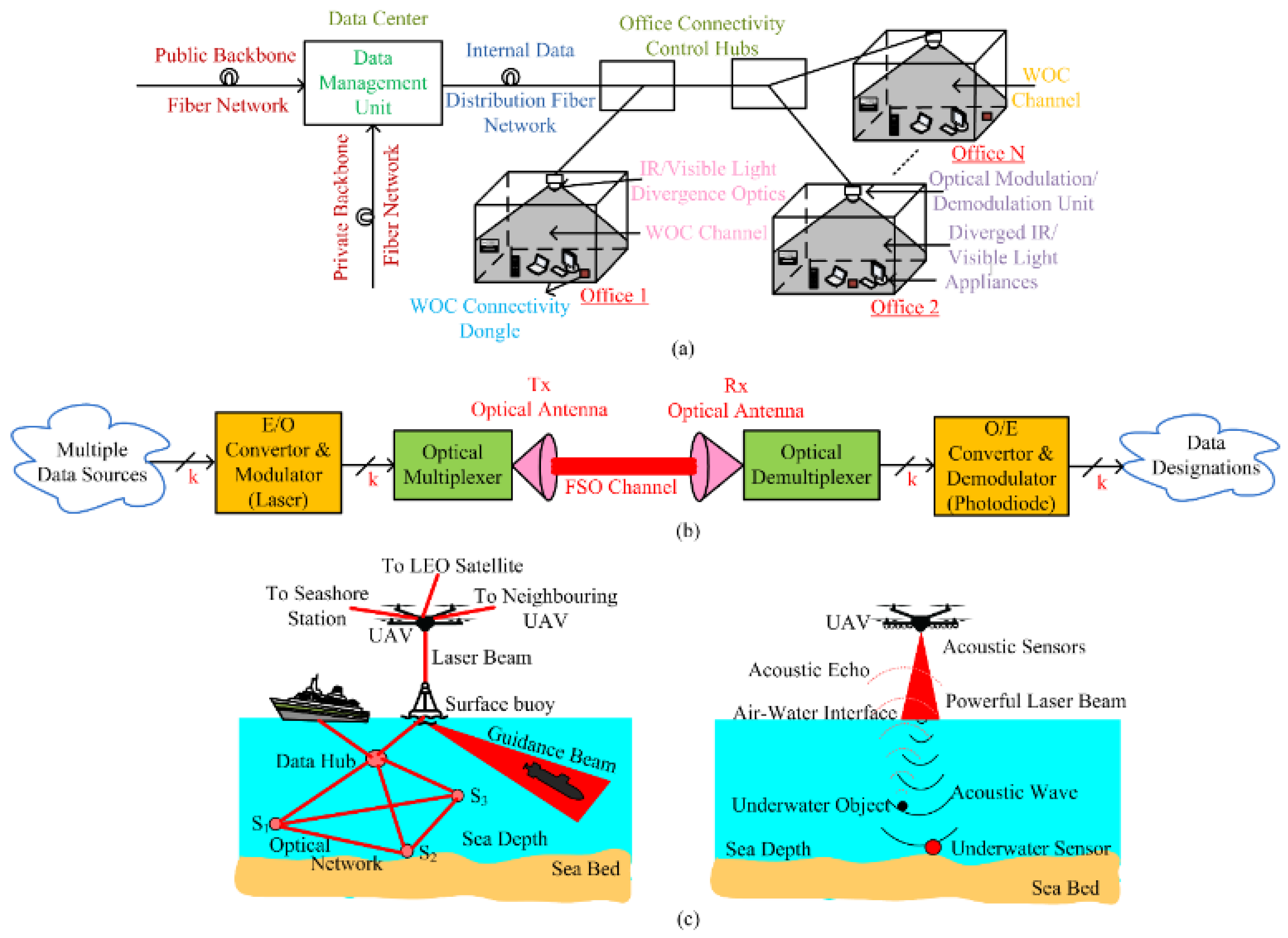
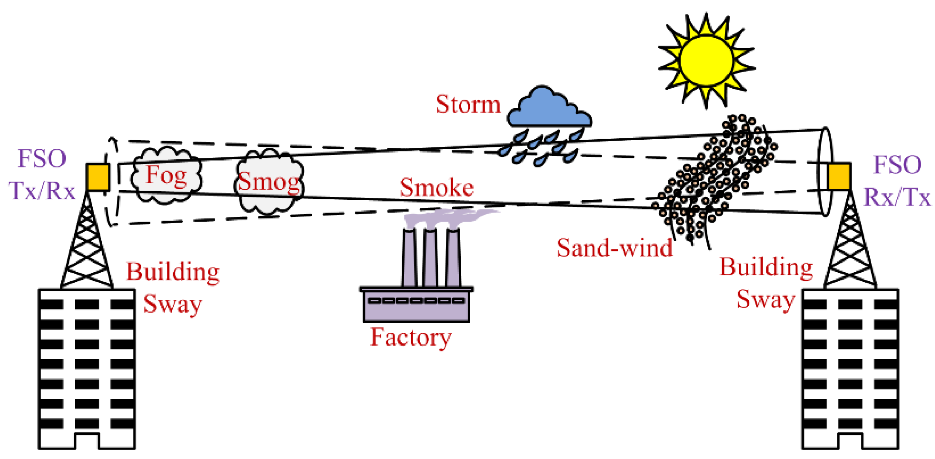
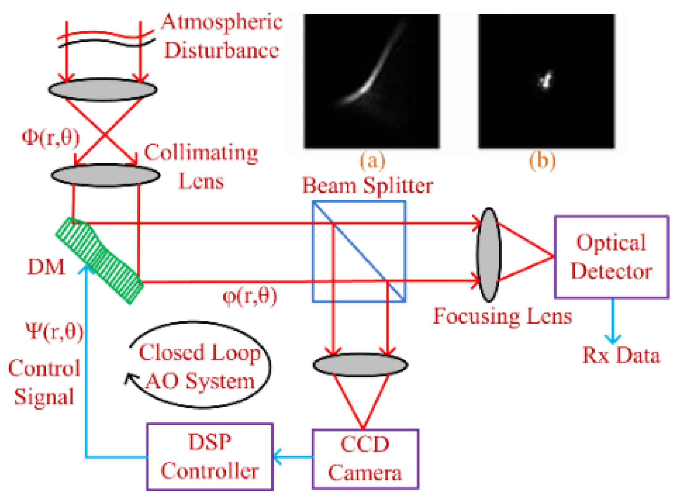
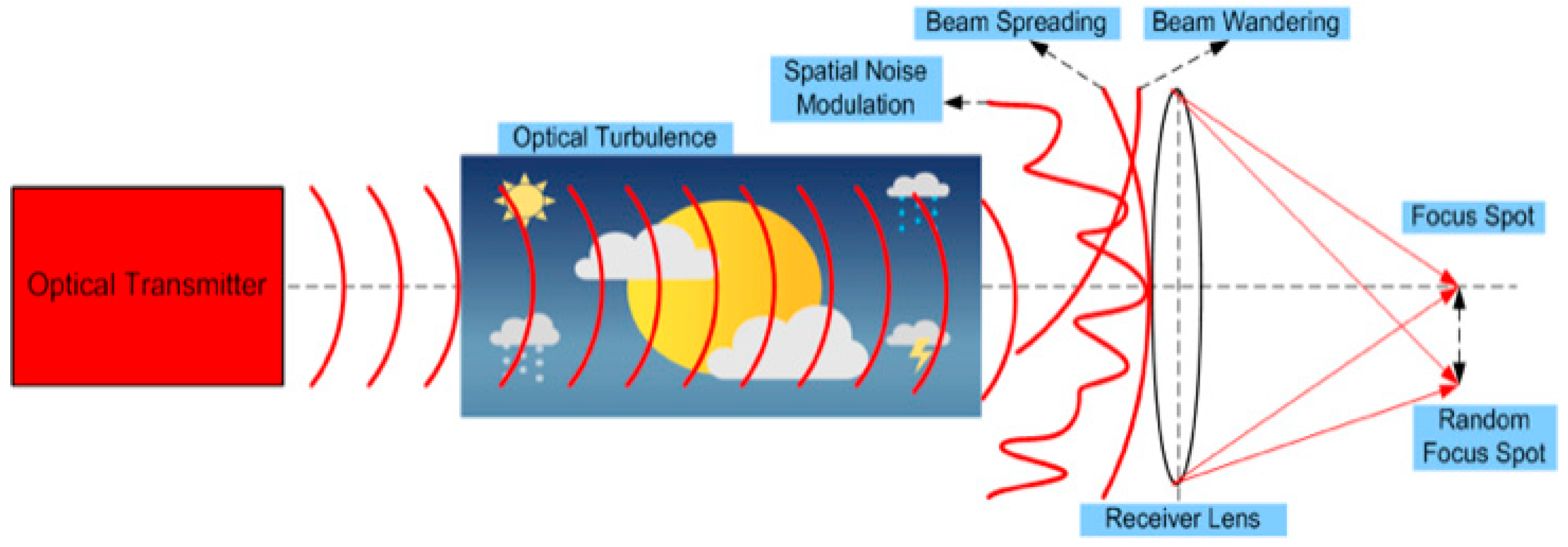
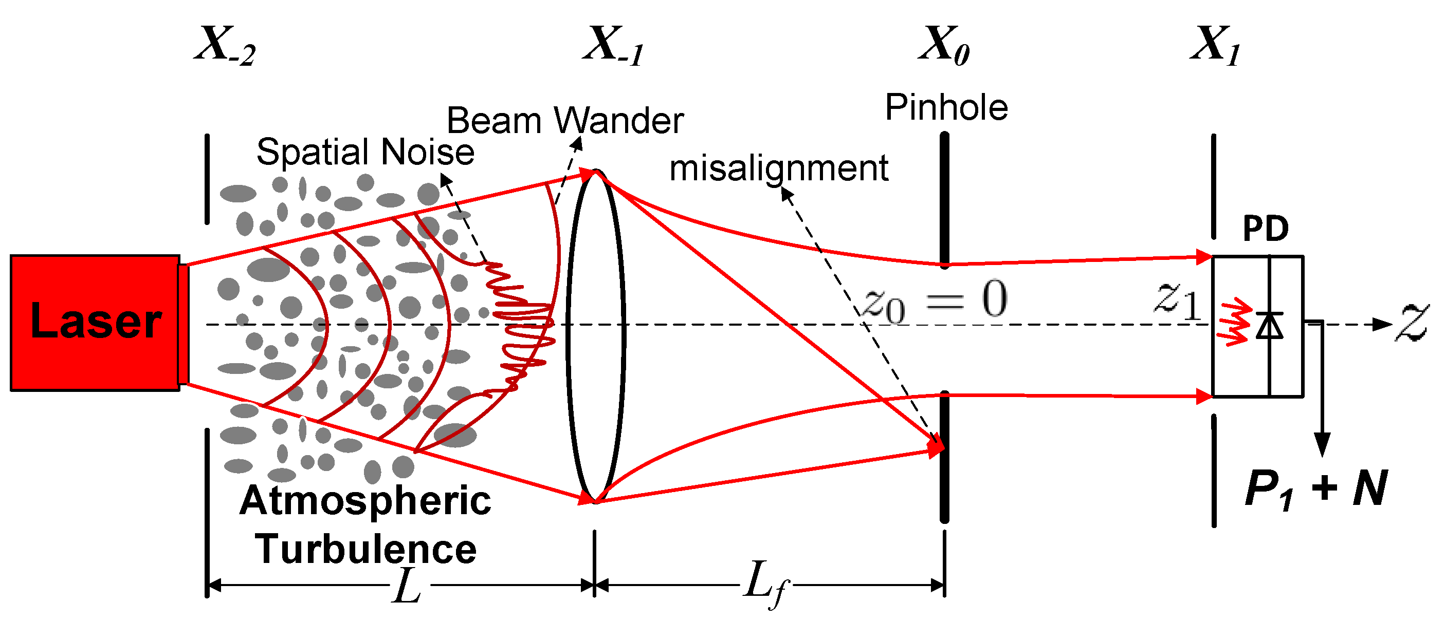
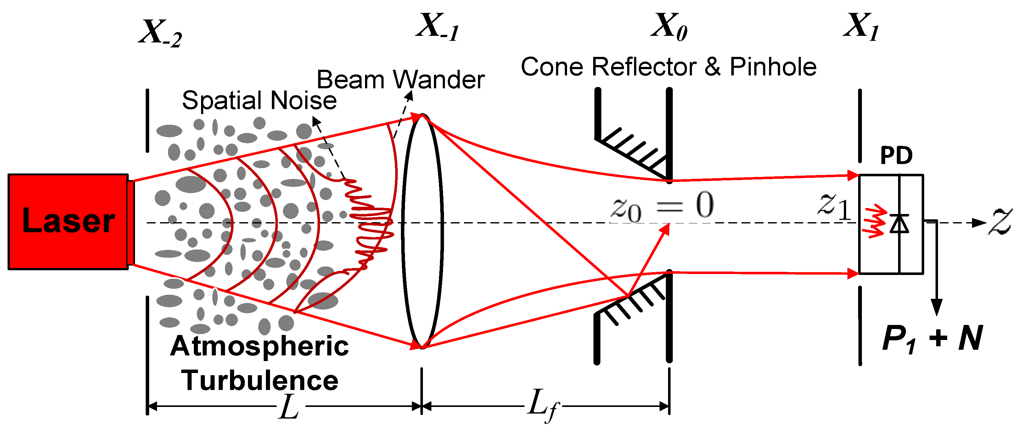
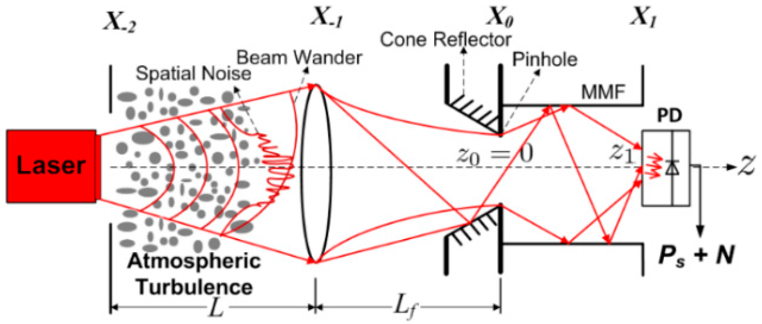
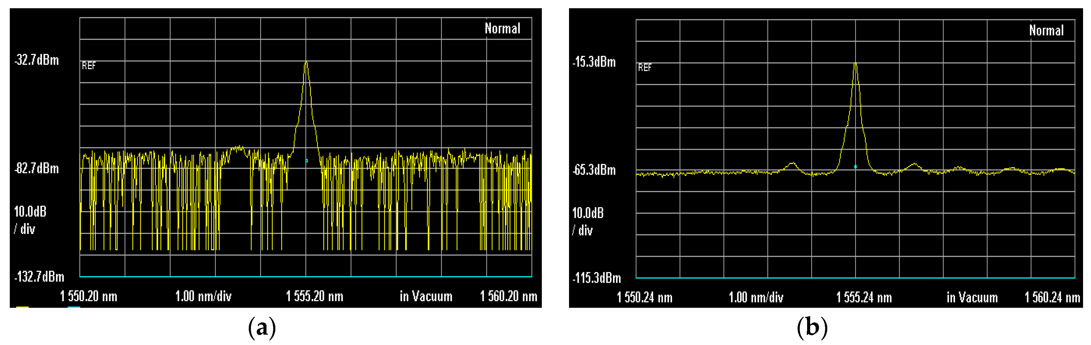
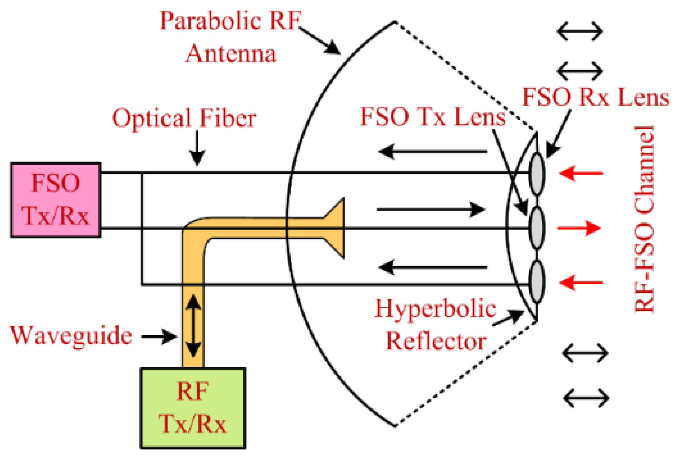
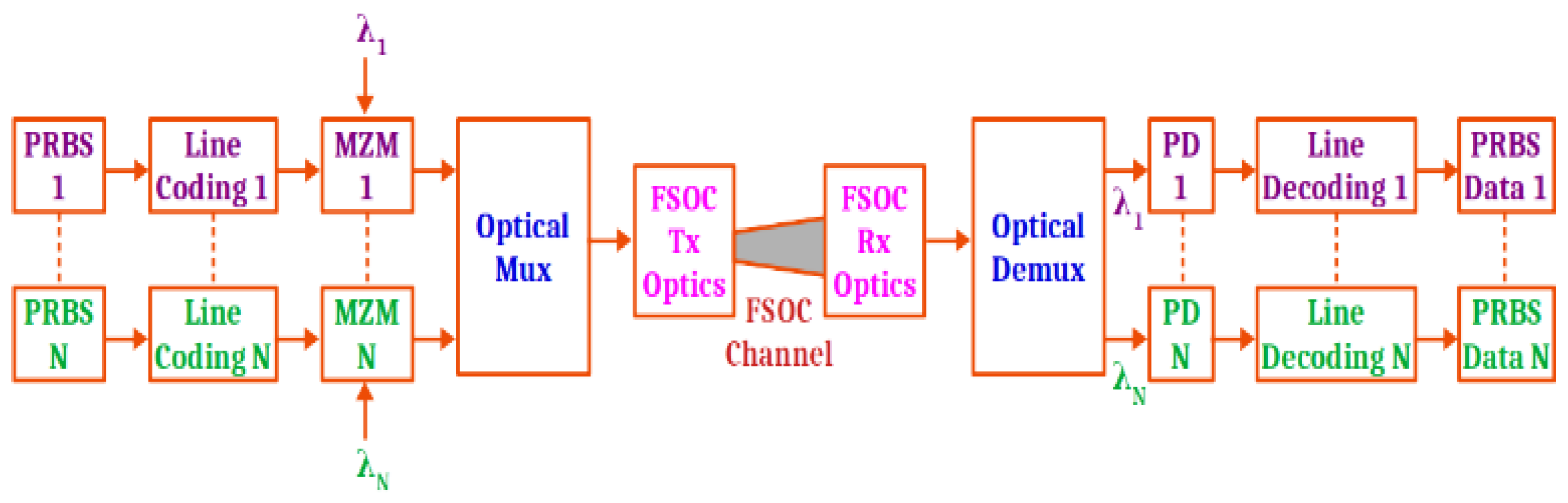
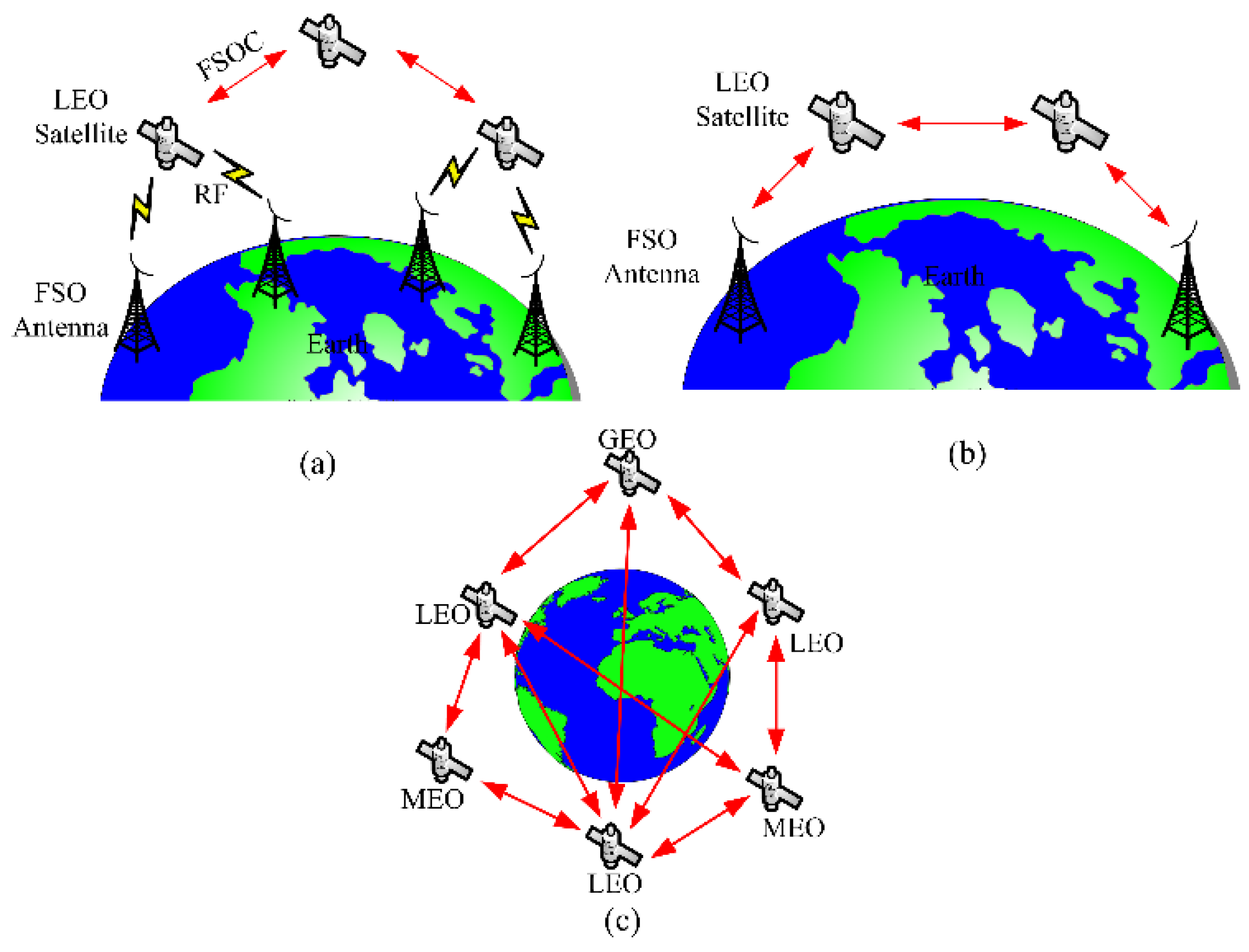
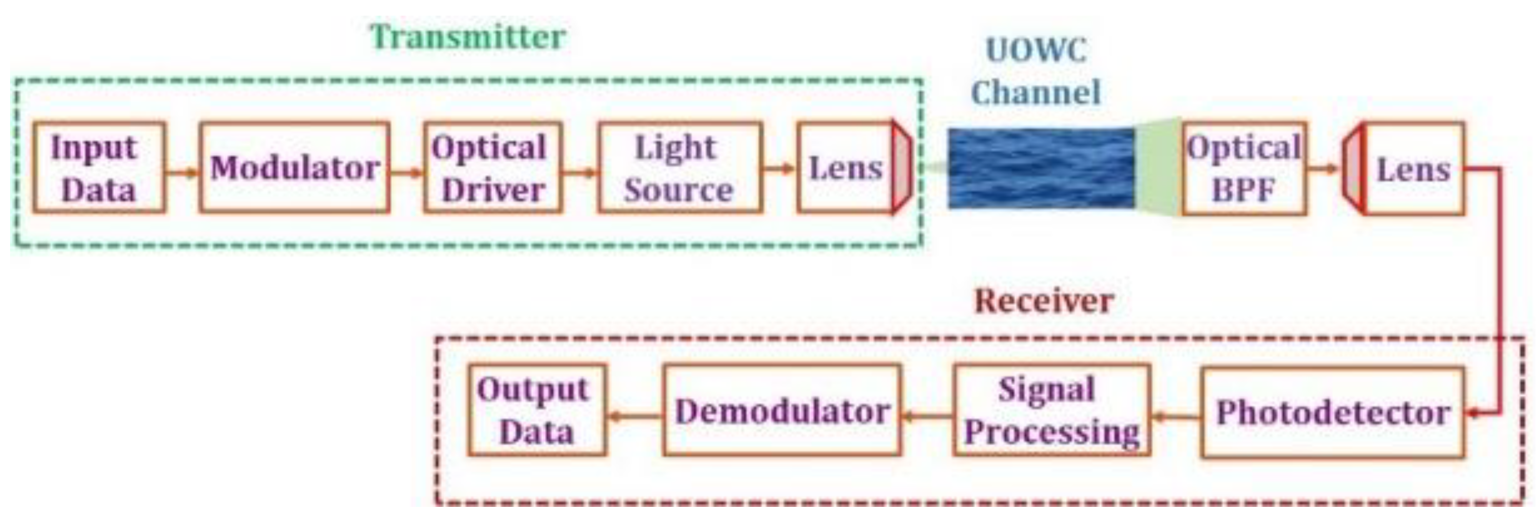
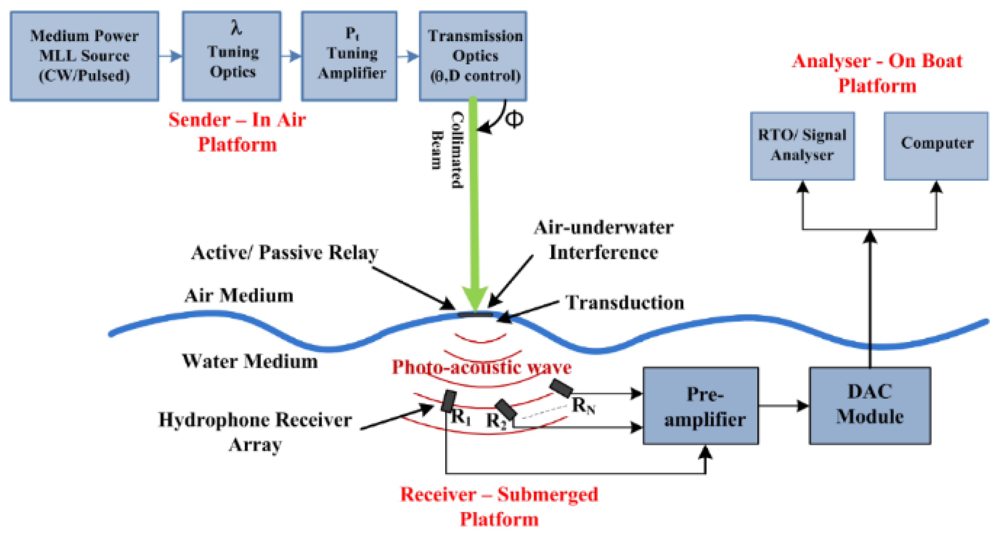
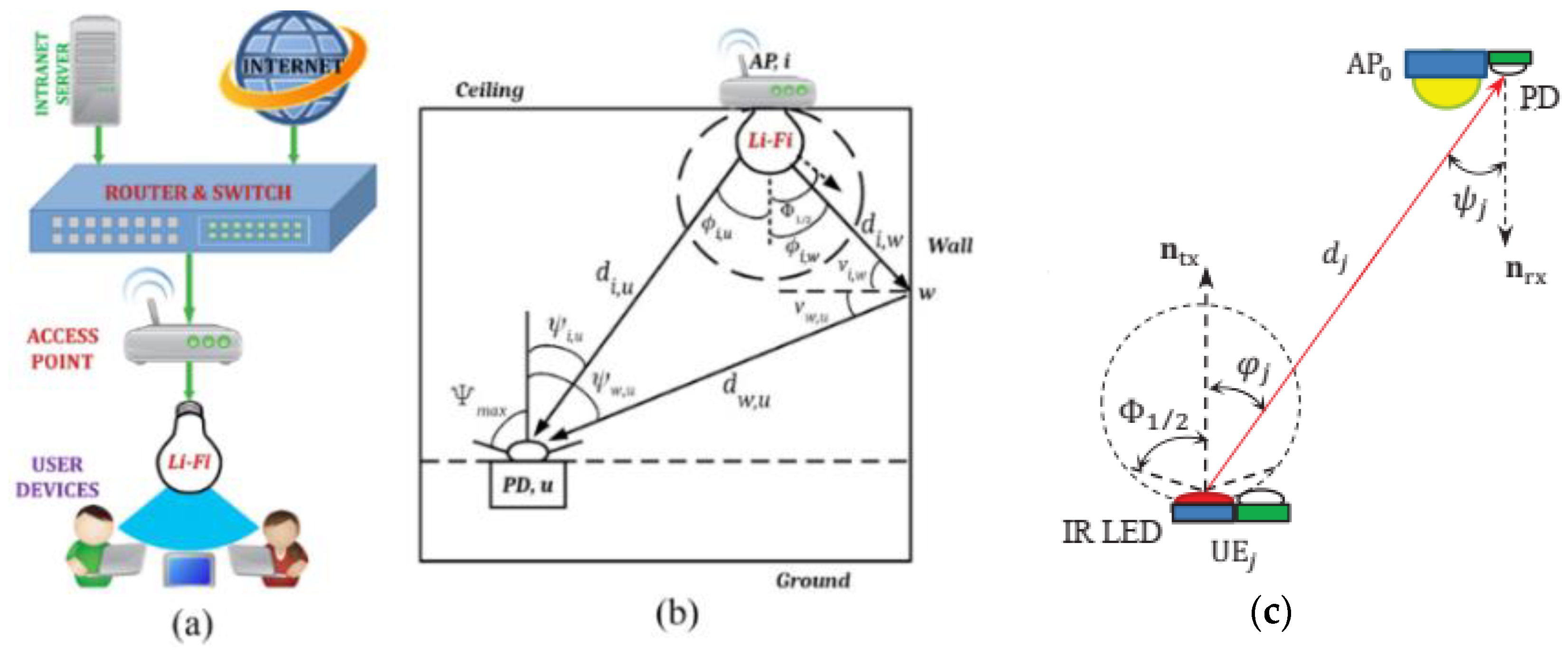
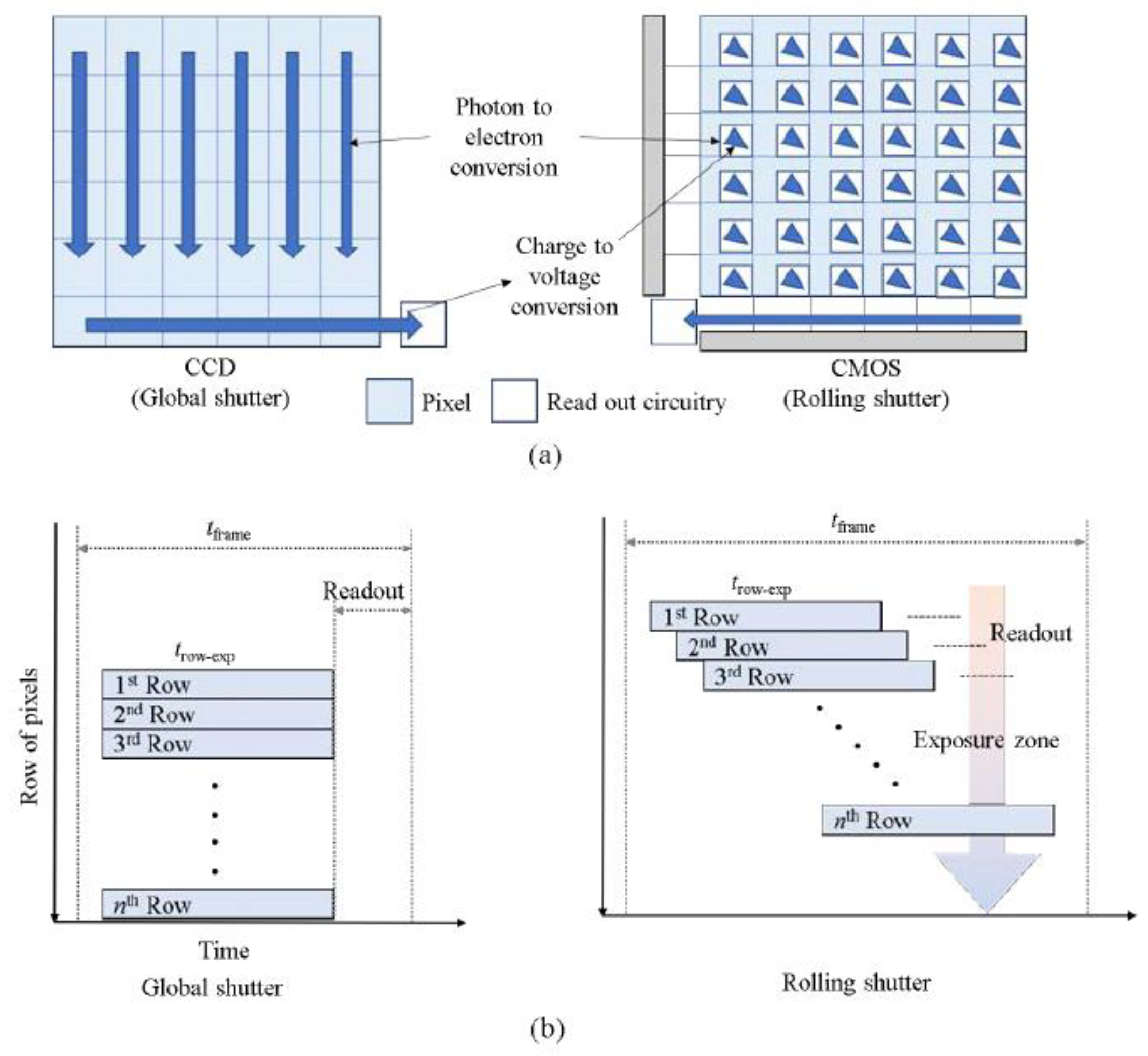
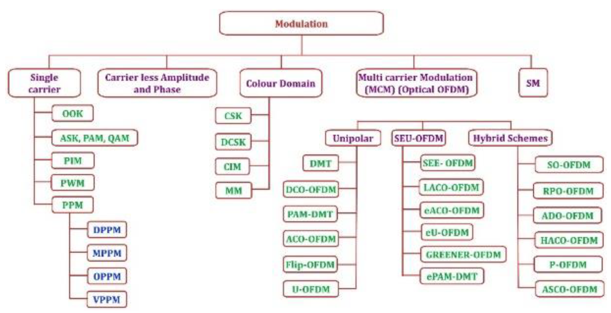
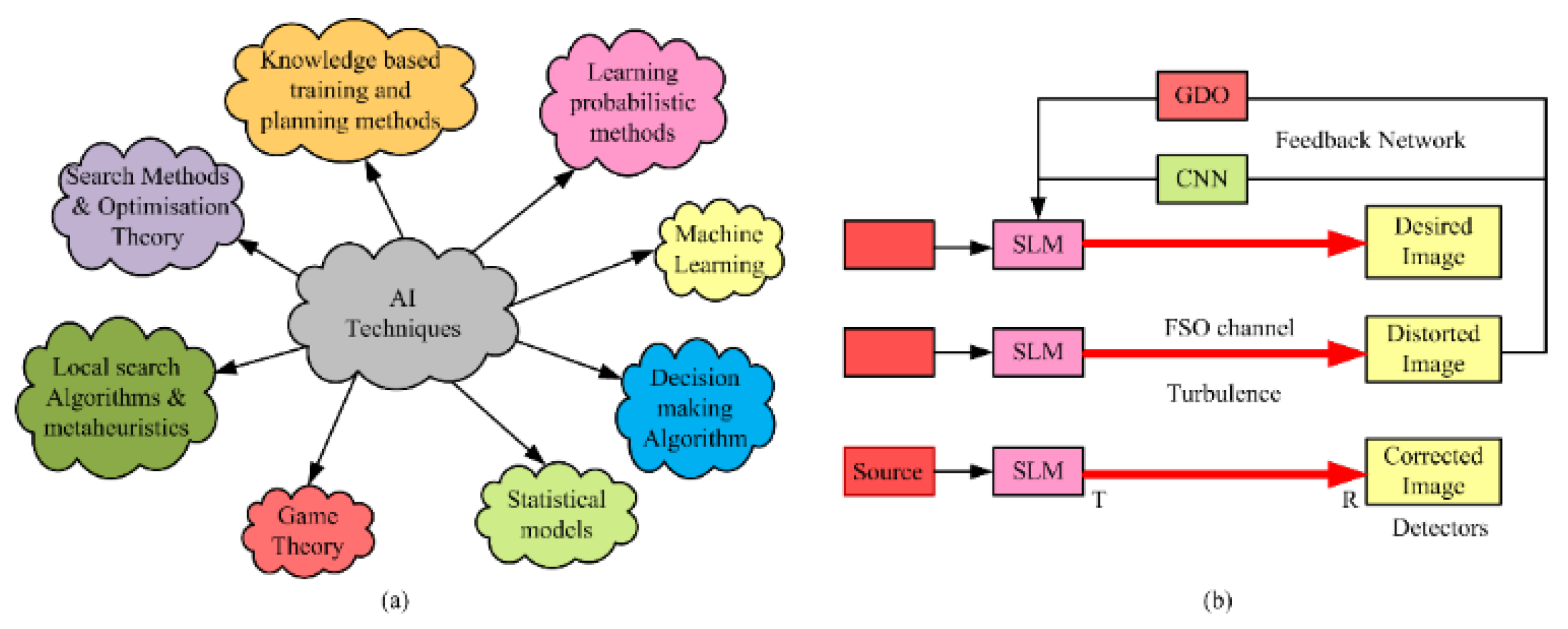
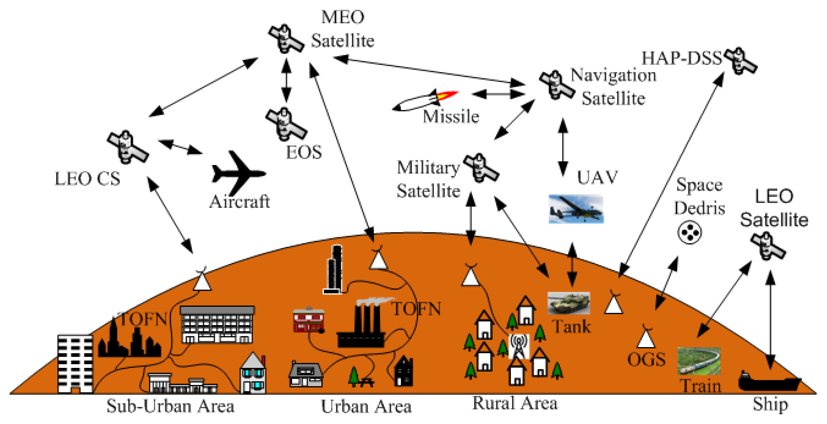
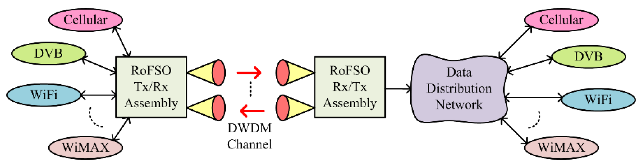
Figure 1. Categorical revolution roadmap of UOC up to today’s technology.
Electronics 12 01922 g001
Figure 2. (a) Acoustic wave transmission over a light beam [4]; and (b) today’s UOC transceiver roof-top system [5].
Electronics 12 01922 g002
Figure 3. (a) The architecture of a WOC network installation; (b) a ‘k’ baseband channel FSO communication system; and (c) OWC systems.
Electronics 12 01922 g003
Figure 4. FSO communication channel factors.
Electronics 12 01922 g004
Figure 5. Aperture-averaged FSO communication receiver.
Electronics 12 01922 g005
Figure 6. Schematic of a PAT system in FSO communication.
Electronics 12 01922 g006
Figure 7. Sensor-less AO system for wavefront aberration correction: inner plot (a) is without AO while (b) is with AO.
Electronics 12 01922 g007
Figure 8. The optical propagation induced by optical turbulence leads to beam wandering, beam spreading, and spatial noise modulation and the focus spot becomes random around the optical axis.
Electronics 12 01922 g008
Figure 9. Spatial filtering using pinhole installed before the PD.
Electronics 12 01922 g009
Figure 10. The cone reflector and pinhole as the optical spatial filter to improve the DD method.
Electronics 12 01922 g010
Figure 11. The OSF composed of a cone reflector, pinhole, and MMF as the optical filter to improve the FD method.
Electronics 12 01922 g011
Figure 12. The sample of the signal spectral measurement at 1555.2 nm from the output of DD and the OSF. (a) The received signal for DD without implementing an OSF; and (b) the signal spectral measurement produced by the OSF. Both are under a strong turbulence condition.
Electronics 12 01922 g012
Figure 13. The results of turbulence effects into signal reception by PD, producing noise instead of signal.
Electronics 12 01922 g013
Figure 14. The low-pass filter in the output of the PD to minimize the output of noise caused by shot and thermal noise.
Electronics 12 01922 g014
Figure 15. The optical relaying networks in FSO composed of nodes at the spacing of Li.
Electronics 12 01922 g015
Figure 16. The configuration of a node composed of optical amplifiers, OA-1 and OA 2, in the AR and AF schemes.
Electronics 12 01922 g016
Figure 17. The OBPF implemented in a node-n to minimize signal with ASE, background noise, and noise modulation from an optical propagation transmitted by a previous node.
Electronics 12 01922 g017
Figure 18. Simplified illustration of a Ro-FSO simplex system.
Electronics 12 01922 g018
Figure 19. MZM with (a) single- and (b) dual-control arms.
Electronics 12 01922 g019
Figure 20. Top level schematic of a full-duplex Ro-FSO system.
Electronics 12 01922 g020
Figure 21. Design of an integrated RF–FSO antenna.
Electronics 12 01922 g021
Figure 22. Schematic of WDM in FSOC system.
Electronics 12 01922 g022
Figure 23. The DWDM-supported next-generation FSO network.
Electronics 12 01922 g023
Figure 24. Schematic of SCM-based FSO system.
Electronics 12 01922 g024
Figure 25. WiMAX top-level architecture.
Electronics 12 01922 g025
Figure 26. FSO-communication-supported WiMAX architecture.
Electronics 12 01922 g026
Figure 27. Different installation scenarios of satellite FSOC networks: (a) RF and FSOC link; (b) direct satellite FSOC link; and (c) global satellite FSOC link.
Electronics 12 01922 g027
Figure 28. The FSO in the configuration of deep-space optical relaying networks (DSORN) as the communication platform between Earth to Mars.
Electronics 12 01922 g028
Figure 29. UWOC system architecture.
Electronics 12 01922 g029
Figure 30. Communication network architecture for underwater, air, and space connectivity.
Electronics 12 01922 g030
Figure 31. A top-level scheme for a PAC system and its performance analysis.
Electronics 12 01922 g031
Figure 32. (a) Li-Fi downlink configuration; and (b) indoor Li-Fi downlink propagation geometry; (c) Indoor Li-Fi uplink propagation geometry.
Electronics 12 01922 g032
Figure 33. (a) Illustration of a Li-Fi indoor network; and (b) Li-Fi fundamental sectional blocks.
Electronics 12 01922 g033
Figure 34. (a) Typical VLC system block diagram; and (b) indoor visible light propagation model.
Electronics 12 01922 g034
Figure 35. (a) Vehicle–VLC communication scenarios; and (b) continuous data connectivity via street lights.
Electronics 12 01922 g035
Figure 36. Top level schematic of a typical OCC system.
Electronics 12 01922 g036
Figure 37. (a) CCD and CMOS image sensor; and (b) global and rolling shutter mechanisms.
Electronics 12 01922 g037
Figure 38. Various modulation techniques being used in WOC.
Electronics 12 01922 g038
Figure 39. (a) AI design subfields and techniques, and (b) schematic of turbulence mitigation feed-back network with CNN and GDO.
Electronics 12 01922 g039
Figure 40. (a) VLC-based energy harvesting model; (b) receiver based on time switching; (c) receiver based on signal component separation; and (d) receiver based on PEC architectures.
Electronics 12 01922 g040
Figure 41. Next generation UOC network: terrestrial optical fiber network (TOFN), optical ground station (OGS), lower-earth-orbit control station (LEOCS), medium earth orbit (MEO), earth observation satellite (EOS), and HAP deep-space satellite.
Electronics 12 01922 g041
Figure 42. UOC network with DWDM access technique for the NGN.
Electronics 12 01922 g042
Table 1. List of Li-Fi system manufacturers (All accessed on 15 January 2023).
NoLi-Fi System ManufacturerWeb Link
1M/s Pure Li-Fiwww.purelifi.com
2Oledcommwww.oledcomm.com
3Li-Fihttps://lifi.co/
4Global Li-Fihttp://globallifitech.com/
5Lifxhttps://www.lifx.com/
6LVXhttp://www.lvx-system.com/
7Wiprohttps://www.wipro.com/
8M/s Basic6http://www.basic6.com/
9Firefly Li-Fiwww.fireflylifi.com
10Velmenniwww.velmenni.com
11VLNcommwww.vlncomm.com
12Lumefficienthttps://lumefficient.com/
13Signifywww.signify.com
14General Electrichttps://www.ge.com/
15Koninklijke Philips N.V.https://www.philips.com/global
16Panasonic Corporationhttps://www.panasonic.com/global/home.html
17Acuity Brands Inc.https://www.acuitybrands.com/
18Light Pointe Communications Inc.https://www.lightpointe.com/
19Fsona Networkshttp://www.fsona.com/
20Infinity Technology Serviceshttps://www.infinitygroupcorp.com/
Table 2. Synopsis of hybrid and convergent systems with their applications.
ContextType of ApplicationRef.DescriptionHybrid Network Type
IndoorLink reliability improvement, energy efficiency, secrecy performance, energy harvesting, and the IoT[390,391,392,393,394,395,396,397]Convergence of two or more different networks improves link reliability.WiFi/VLC, RF/VLC, VLC/PLC, PLC/VLC/RF, WiFi/LiFi, VLC/Femto-cell, Femto-cell/LiFi, and LiFi/RF
Localization/ positioning/ navigation[398,399,400,401]A hybrid system is used to improve accuracy in indoor CATV, mobile robots, and smart phones.SMF/PCF/GI-POF/VLC, Infrared/VLC, LiFi/OCC, Macro-cell/OCC, and Macro-cell/VLC
Load balancing, handover mechanism, and high-data-rate communication[402,403,404,405,406,407,408,409,410,411,412,413,414,415,416,417,418,419]By providing network-sharing capabilities, hybrid systems ensure high-data-rate services. From extremely congested and low-capacity Wi-Fi, femto-cell, and macro-cell networks, a large percentage of traffic is diverted to the VLC or Li-Fi network.VLC/WiFi, VLC/LTE, VLC/Femto-cell, PLC/VLC, and VLC/RF
Backhaul connectivity[420]For backhaul connectivity, traffic from an RF-based network is moved to a VLC network.Microwave/FSO
Cellular networks[421]Rate analysis and CoverageRF/VLC
eHealth[422,423]Remote patient monitoringOCC/Bluetooth
OutdoorPositioning and navigation[424,425,426]Space–air–ground–ocean-integrated communicationFSO/VLC, and RF/OCC
Vehicular communication[427,428,429,430,431]V2V, V2I communication, Topology controlWiFi/VLC, VLC/RF, V2X, RF/OCC, and RF/FSO
UnderwaterLink reliability, high data rate, ocean monitoring, and Internet of Underwater Things (IoUT)[432,433,434,435]Link range, type of water, environment and applications based on these. Acoustic or RF or UWOC link is considered.RF/FSO, and acoustic/FSO
Convergent Indoor—OutdoorHigh-data-rate communication, the IoT, and 5G/6G[436,437,438]To overcome the bandwidth constraint in last-mile and last-meter access networks.FSO/VLC, VLC-FSO, and VLC
Convergent Outdoor—UnderwaterHigh-data-rate communication, IoUT, ocean monitoring, and underwater wireless optical sensor networks[439,440,441,442,443]Multiple hops are used to connect ground stations to the underwater environment.FSO-UWOC, UWOC-FSO, and RF-UWOC
Disclaimer/Publisher’s Note: The statements, opinions and data contained in all publications are solely those of the individual author(s) and contributor(s) and not of MDPI and/or the editor(s). MDPI and/or the editor(s) disclaim responsibility for any injury to people or property resulting from any ideas, methods, instructions or products referred to in the content.

