1. Introduction
Wireless power transfer (WPT) technology is a power transmission technology that can wirelessly transfer power from a power source to a load without direct contact [
1,
2]. Recently, due to the high reliability, safety, and convenience of WPT technology, WPT equipment has been widely used in electric vehicles (EVs) [
3,
4], rail vehicles (RVs) [
5], and industrial AGV, especially in some high-power application scenarios.
Limited by the voltage and current capabilities of high-frequency semiconductor devices, it is difficult for a single inverter to meet the high-power requirements of WPT systems. Therefore, in the high-power WPT system, the design of multiple inverters [
6] or multiple inverter bridges [
7] is usually adopted to adapt to high-power operation scenarios. In the multi-inverter system, since the total power of the system is shared by multiple inverters or multiple inverter bridges, the operating power of each inverter or inverter bridge will be significantly reduced. For example, in literature [
8], a parallel inverter topology is used to increase the transfer power of the WPT system. However, it used a 380 V AC power supply to feed the inverters. When the WPT system is running in a high-power power transmission state, the parallel inverter topology will cause a very large bus current and heat loss, so that the transmission power and efficiency of the WPT system will be reduced.
In high-power application scenarios, the medium-voltage DC distribution network is usually equipped, so the high-power electrical equipment can directly obtain high-power DC power. In this case, a higher input voltage can effectively reduce the bus current in high-power scenarios, thereby reducing the heat loss of the inverter and improving the overall power and efficiency of the system.
Since the voltage capability of high-frequency semiconductor devices is usually limited, a multi-level inverter topology can be used to withstand higher input voltages, such as series input parallel output (ISOP) inverter topology [
9]. This topology can reduce the input voltage of each inverter in the system. Therefore, the system can run under the condition of several thousand volts of DC input voltage only by using inverters with a withstand voltage of hundreds of volts. Generally, in the ISOP topology, in order to make the inverters output in parallel, each inverter must be equipped with a front DC/DC isolation transformer to isolate the input power so that the output of each inverter is at the same potential. The disadvantage of the topology is that the isolation transformer makes the system circuit more complicated and inevitably reduces the overall transmission efficiency of the system.
In the traditional WPT topology, only one primary coil and one secondary coil are included. Therefore, in the process of wireless charging using the traditional WPT system, to ensure that the output power meets the load’s requirement, the primary coil and the secondary coil must be perfectly aligned [
10]. For perfect alignment between the transmission coils, the driver must perform cumbersome positioning operations during parking, or equip a precise automatic positioning system for the EVs and RVs. Obviously, it is difficult for the WPT system to achieve perfect positioning of EVs and RVs in practical applications. However, if the anti-offset ability between the transmission coils can be improved so that the EVs and RVs do not need to be perfectly aligned during parking and charging and only need to enter a larger parking area to obtain sufficient power through the WPT system, this will greatly reduce the difficulty of positioning and charging. In order to make the traditional WPT system have a better anti-offset ability, paper [
11] proposed a series–parallel–series (SPS) topology. Research results showed that the maximum offset of one-to-one transmission coils can reach 25%. In order to improve the anti-offset ability of the WPT system, paper [
12] designed a system with multiple primary loops and increased the operating frequency of the inverters to MHz. However, in the EVs wireless charging standard established by the Society of Automotive Engineers (SAE) J2954
, the best charging frequency is from 80 kHz to 90 kHz, and the operating frequency of the system does not meet the standard. At the same time, in the topology, there are some dead zones with extremely low energy transmission power, so the topology cannot guarantee the EVs and RVs always receive sufficient power.
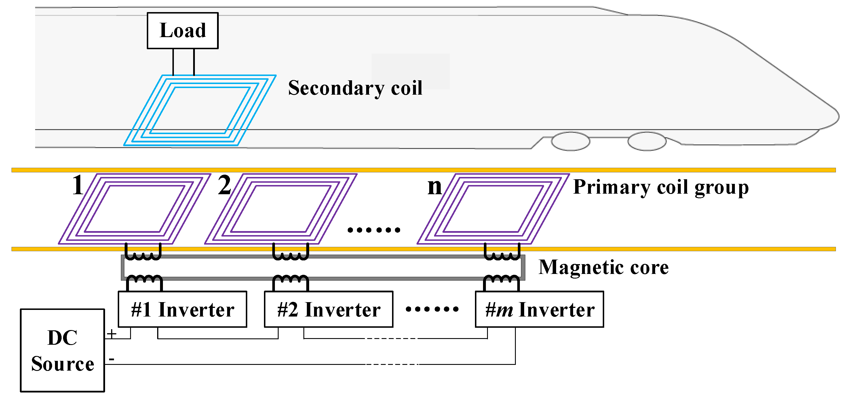
In order to solve the above problems, the paper proposes a high-voltage wireless charging anti-offset WPT topology based on multi-winding transformers for EVs and RVs. The overall structure diagram of the topology is shown in
Figure 1. In order to meet the requirement of high-voltage and high-power wireless charging, the input of the inverters is connected in series to achieve high-voltage input, and the output of the inverters is connected to a multi-winding transformer, which can output the high-power of the series inverters in parallel equivalently. Since the output of each inverter is connected to a primary winding of the multi-winding transformer, the output power by the inverters is actually connected in parallel through the superposition of the magnetic field, instead of the output of each inverter being directly connected in parallel. Therefore, in the topology, there is no need to design a DC/DC isolation circuit. Even if the input potential of each inverter is different, through the design of a multi-winding transformer, the power at the output of the inverters can be in parallel. The number of series inverters can be flexibly adjusted according to the inverter’s withstand voltage capability and the voltage level of the DC source. The system only needs to adjust the number of primary windings of the multi-winding transformer according to the number of series inverters. In order to improve the anti-offset ability of the transmission coils, the primary side of the system adopts the design of multiple transmitting coils. The multiple primary coils can obtain power directly from the multi-winding transformer through the primary loops. All primary coils are placed side by side on the same plane. Based on the current parking position of the vehicle, one or more primary coils can be selectively connected for power transmission, and the total number of primary coils can be flexibly adjusted according to the anti-offset ability required by the system. The secondary coil can transmit the received power to the load. Therefore, within the coverage of the transmitter coil group, the anti-offset capability of the WPT system can be improved.
3. Simulation and Verification
First, this chapter proposes the calculation method of mutual inductance when the primary and secondary coils are offset; then, when the secondary coil is in different positions, the change of mutual inductance between the primary coils and secondary coil is simulated to study the role of each primary coil in the WPT system; finally, in order to improve the anti-offset ability of the WPT system, a multi-coil adaptive working mode is proposed by the simulation of the load voltage.
3.1. Calculation Method of Mutual Inductance
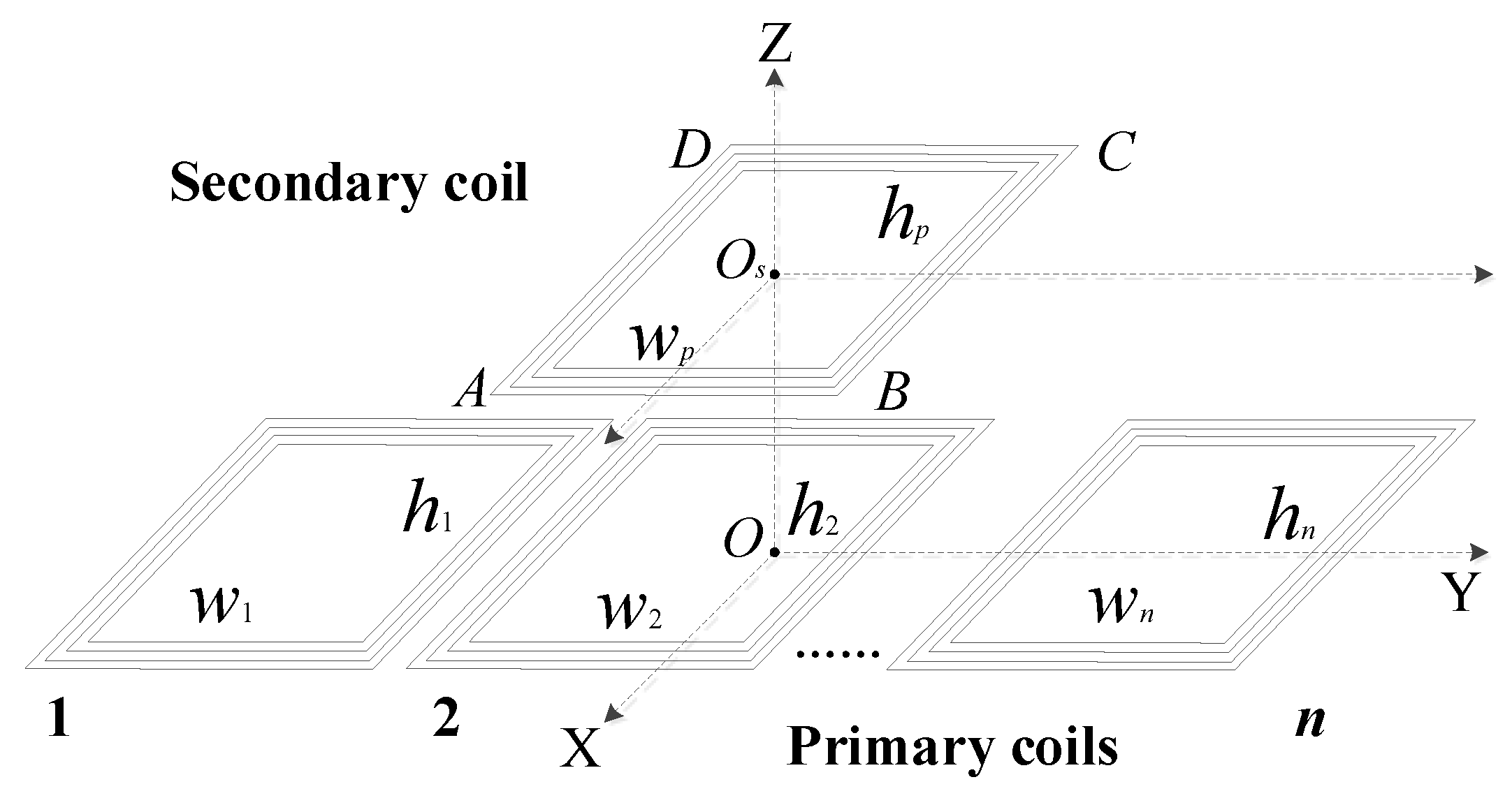
When an EV or RV enters the charging area, the schematic diagram of the position of primary and secondary coils is shown in
Figure 3.
A calculation method of mutual inductance of two coaxial spiral rectangular coils was introduced in [
13]. Reference [
14] extended this method and derived the calculation method of mutual inductance when the solenoid rectangular coils are not aligned. The mutual inductance between any two coils can be expressed as:
where
and
are the turns of the two coils.
is the magnetic flux generated on the
turn of the secondary coil along the Z-axis direction when a current with an effective value of 1 A flows on the AB side of the
turn of the primary coil, where
,
, and
are the same.
3.2. Mutual Inductance Simulation between Primary and Secondary Coils
In order to simulate the actual working situation of many-to-one WPT system, this chapter designs a many-to-one WPT topology Matlab model with four primary coils and a secondary coil. In the model, the length and width of each coil are 240 mm and 180 mm, and the number of turns is 17. When the offset of the primary coil group and the secondary coil on the Y axis and the X axis is zero, the air gap on the Z axis is 40 mm. When the geometric center
of the secondary coil is horizontally displaced from −720 mm to 720 mm along the Y axis relative to the geometric center
of the primary coil group, according to (
29), the mutual inductances between the secondary coil and each primary coil can be calculated by Matlab shown in
Figure 4, where
,
,
, and
are the mutual inductances between the primary coil 1 to coil 4 and the secondary coil, respectively. For a WPT system, to transmit power wirelessly, there must be strong coupling between the primary and secondary coils.
For example, in
Figure 4, when the secondary coil is located in the central area (from 85 mm to 155 mm) with strong mutual inductance (greater than 40
H) of the primary coil 2, the value of
is much larger than
,
, and
, which means the mutual inductances between the primary coil 1, coil 3, coil 4, and the secondary coil are very weak and can be ignored. Therefore, in order to simplify the analysis, these three coils can be ignored in the interval. In other words, in the range where the value of
is much larger than
,
, and
, other primary coils can be ignored except for the coil 2. However, in the range from −85 mm to 85 mm, although the values of
and
do not exceed the mutual inductance in the central area, they are still much larger than the values of
and
. According to (
26), if the two primary coils can work at the same time, the system can still perform wireless power transmission. Therefore, within this interval,
and
cannot be ignored, whereas the values of
and
can still be ignored. In the other intervals in
Figure 4, the mutual inductance value is the same as the two cases that have been analyzed, so it will not be repeated.
The above analysis shows that under the condition of the coil size given in this chapter, depending on the relative position of the primary coil group and the secondary coil, only one or two primary coils are needed to effectively transmit power wirelessly. If the size of the coils change, the mutual inductance simulation model can be used to deduce which primary coils are needed for power transmission in the corresponding interval. Based on the coil size given in this chapter, in the next section, the situations of a certain primary coil working alone and two primary coils working together will be discussed.
3.3. Simulation of Primary Coils Working Mode
The simulation topology in this chapter is a two-to-one WPT system with two series inverters.
Table 1 lists a set of simulation parameters for the two-to-one WPT systems. Assuming that the parameters of the two inverters are the same and the maximum input voltage is 30 V, so this chapter sets the simulation parameter of the DC voltage source
to 60 V. According to the parameters in
Table 1, combined with (
23) to (
29), the power transmission characteristics of the system described in this chapter can be simulated when the secondary coil is displaced horizontally along the Y axis. At the same time, when the load impedance is constant, the power of the load is positively correlated with the load voltage. Therefore, the load voltage is selected in this chapter to reflect the power received by the load.
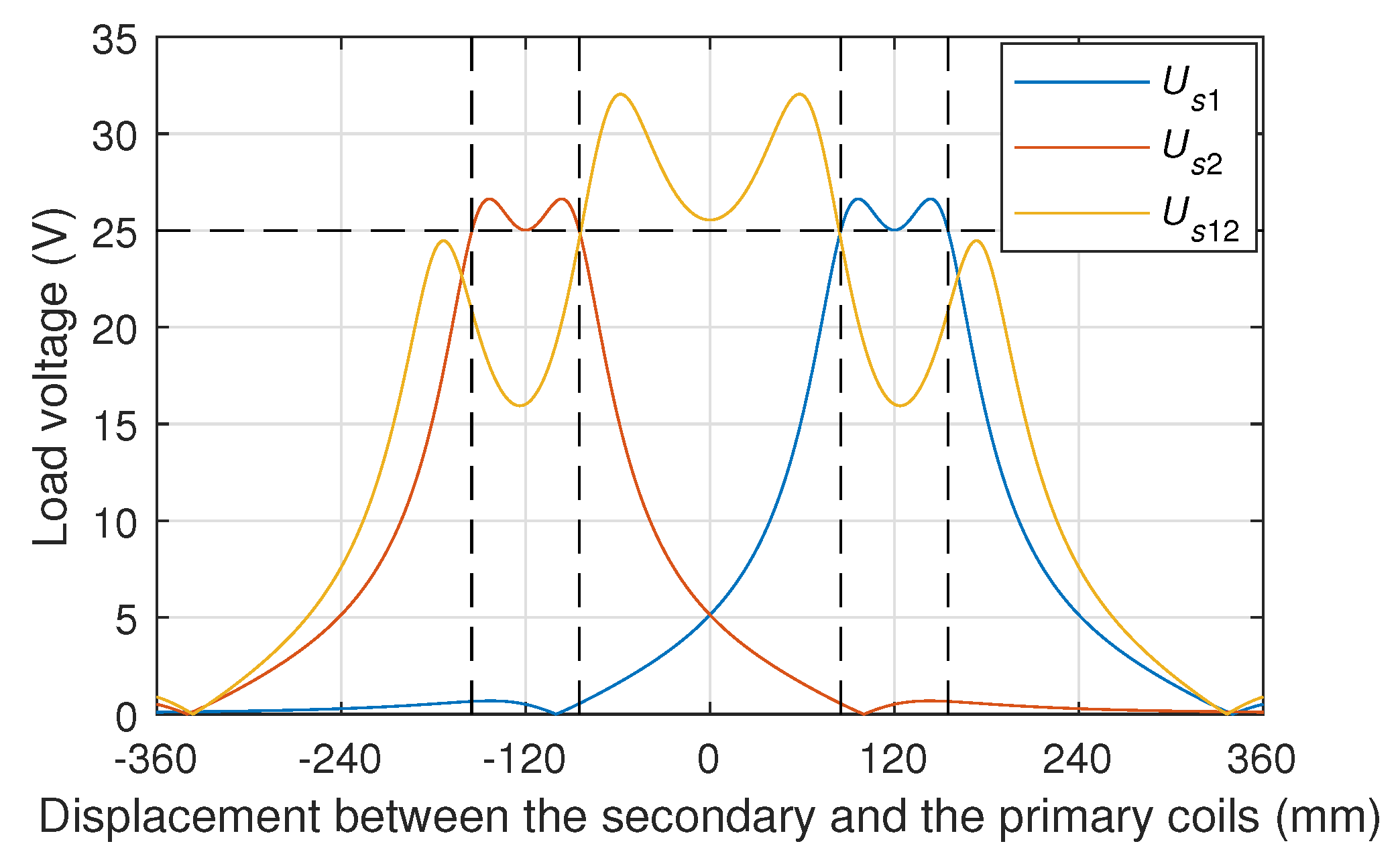
Figure 5 is a simulation diagram of the load voltage when the secondary coil is moved from −360 mm to 360 mm and the two primary coils of the two-to-one WPT system work independently. In
Figure 5,
and
are the load voltage when the 1st and 2nd primary coils work independently, respectively. In order to keep the load voltage continuous and the load voltage as high as possible, the threshold voltage of the load can be selected as 25 V. In the case, the load can be positioned from 85 mm to 155 mm (first primary coil) and from −155 mm to −85 mm (second primary coil). Obviously, the range of the positioning area of the EVs or RVs is only two non-adjacent 70 mm areas in
Figure 5.
Obviously, the design of two primary coils can expand the positioning range of the EVs or RVs. However, there is a dead zone with insufficient load voltage between the positioning areas of the two primary coils, and the EVs or RVs still need to be aligned one of them when parking and charging. So, the working mode in which the two primary coils work independently cannot improve the anti-offset capability of the WPT system.
Figure 6 introduces the simulation curve of the transmission characteristics of the many-to-one WPT system when the two primary coils are working together. In
Figure 6,
is the load voltage when the two transmitting coils are turned on at the same time.
As can be seen in
Figure 6, if the two primary coils work at the same time, the load voltage can still meet the demand in the dead zone (−85 mm to 85 mm) where the load voltage is insufficient with each primary coil working independently. However, in the area where the load voltage exceeds 25 V (−155 mm to −85 mm, 85 mm to 155 mm) when the two primary coils work alone, the mode that the two coils work at the same time is not conducive to the load voltage. Therefore, the number of primary coils allowed to participate in power transmission can be adjusted according to changes in the parking position of the EVs or RVs, and the working mode is called adaptive working mode, as shown in
Figure 7.
In
Figure 7,
is the load voltage change curve in adaptive working mode, and the threshold voltage is still 25 V at this time. In the adaptive mode of the primary coil group, when the parking position of the EVs or RVs is in the range of −155 mm to −85 mm, the 1st primary coil is turned off, and the 2nd primary coil is turned on and works alone; when the parking position of the EVs or RVs is in the area of −85 mm to 85 mm, both primary coils are turned on and working simultaneously; when the parking position of the EVs or RVs is in the range of 85 mm to 155 mm, the 1st primary coil works alone after being turned on, and the 2nd primary coil is turned off. Therefore, for a many-to-one WPT system with adaptive working mode, the positioning area can be expanded from two non-adjacent 70 mm areas (−155 mm to −85 mm, 85 mm to 155 mm) to a continuous 310 mm area (−155 mm to 155 mm). The positioning range is much larger than 70 mm of a single primary coil, and there is no dead zone. The two coordinates of 85 mm and −85 mm on the X axis are the switching points (SPs) between the single-coil mode and the multi-coil mode in the adaptive working mode.
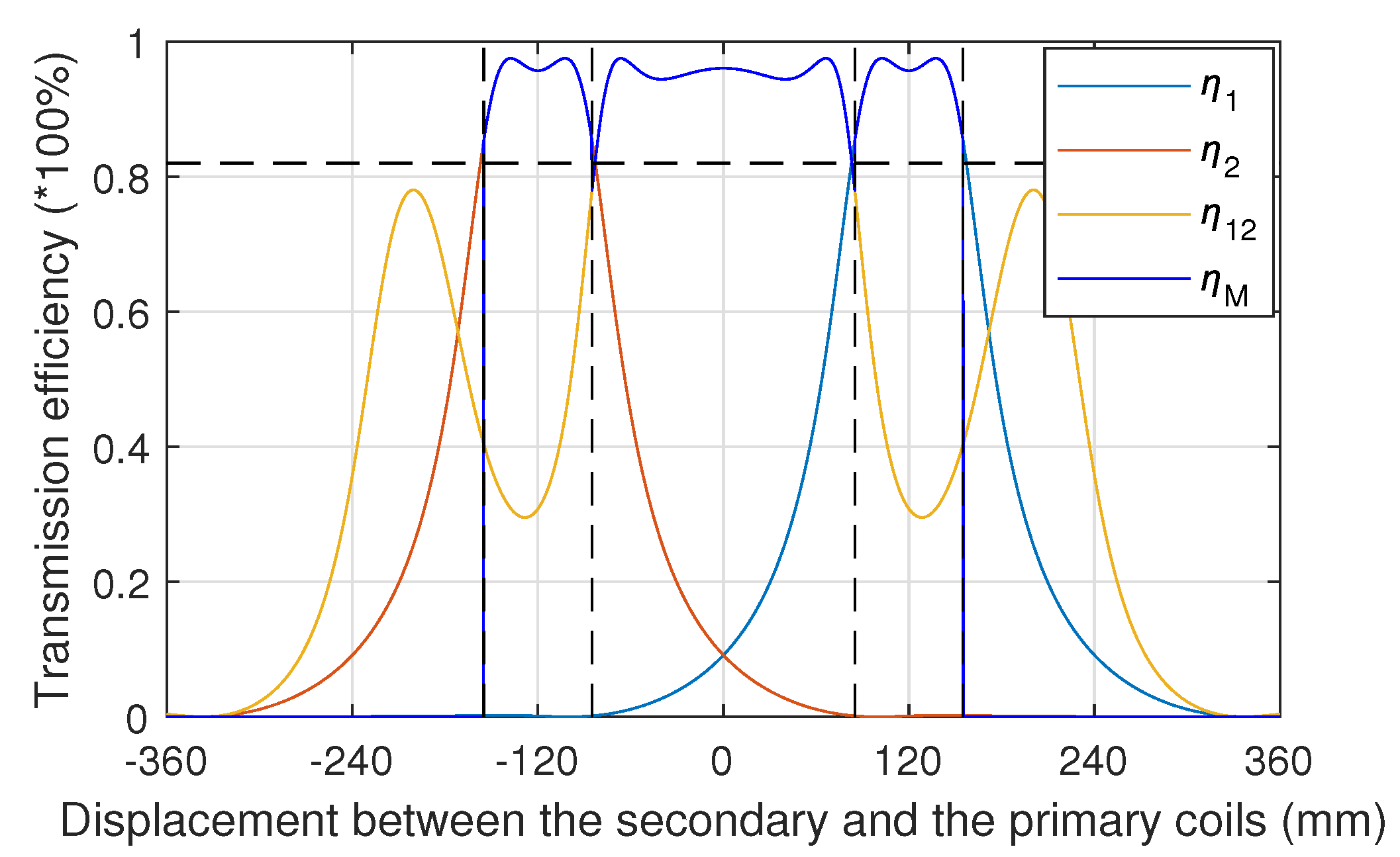
Figure 8 is a graph of power transmission efficiency in the adaptive working mode of a two-to-one WPT system including two series inverters. As can be seen in
Figure 8, under ideal conditions, the system in the continuous area (−155 mm to 155 mm) with the mixed working mode, the energy transmission efficiency of most areas exceeds 90%. Only in the small area near −155 mm, 155 mm and two SPs, the transmission efficiency is lower than 90%, but the minimum efficiency is not lower than 82%.
When the number and size of the coils are fixed, the many-to-one WPT system working in the adaptive mode will provide sufficient power for the the EVs or RVs in a larger continuous range. This allows the EVs or RVs which need wireless charging to park within a large continuous positioning range without requiring precise positioning. Therefore, the many-to-one topology can effectively improve the anti-offset capability of the WPT system.
Although this chapter only discusses the two-to-one WPT system, when the system has more primary coils, the positioning area can obviously be further expanded. In addition, when the system has n primary coils with different sizes, the adaptive work mode can be designed through the coils work mode simulation method introduced in this chapter to improve the anti-offset ability of the WPT system.
4. Prototype Making and Experimental Verification
In order to verify the theoretical analysis and simulation, this chapter presents a prototype of a two-to-one WPT system with two series inverters based on a four-winding transformer, as shown in
Figure 9.
In
Figure 9, the input voltage of the system is fed by an adjustable DC source with a maximum voltage of 64 V. Moreover, the two inverters are driven by a high-frequency signal source at the same time. Therefore, in the case of inverters in series, the system can withstand a maximum of 60 V DC input voltage. The four-winding transformer is made of four isolated Litz wires simultaneously wound on a high-frequency ferrite core. Two windings are connected to the output of two inverters, and the other two are connected to two primary loops. The parameters of two primary and secondary coils are the same, and each are 240 mm by 180 mm rectangular plane solenoid coils l, and the turns are 17. The distance between the centers of the two primary coils is 265 mm. In this case, the measured mutual inductance between the two primary coils is only 4.36
H, which is much smaller than the mutual inductance between the primary coil and the secondary coil. Therefore, the mutual inductance between the primary coils can be ignored. The compensation capacitors of the primary and secondary loops are composed of multiple high-voltage film capacitors with a capacitance of 1 nF. In order to control the on and off of the primary loops, a push switch is provided on the compensation capacitor plates. The vertical air gap between the primary and secondary coils is 40 mm. The secondary loop contains a full-bridge rectifier and two adjustable power resistors with a maximum resistance of 5
. The load voltage and power of the system are measured by a Tektronix PA1000 power analyzer. The main parameters of the prototype are listed in
Table 2. The resistances, inductances and capacitances are all measured by an Agilent E4980A LCR meter at 85 kHz. It is very important to maintain the inverters as zero-voltage-switching (ZVS) for a WPT system, especially for those high power applications [
15]. So the ZVS condition can be obtained via regulating the inverters operating frequency of the WPS system.
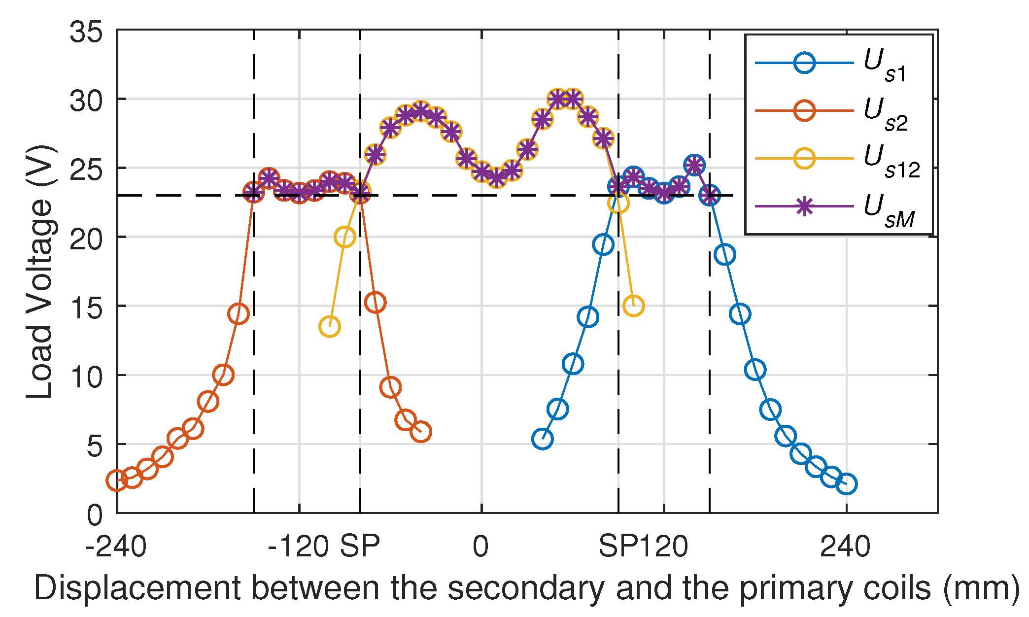
Figure 10 shows the measured load voltage using the two-to-one WPT prototype. In order to measure the load voltage when the secondary coil is placed in different positions, the experiment set the secondary coil to move intermittently from −240 mm to 240 mm at 10 mm intervals. When the two primary coils work independently, the load voltage curves are expressed as
and
, respectively. When the two primary coils work at the same time, the load voltage is
. As can be seen in
Figure 10, when only a single coil is working, the positioning range of the 1st primary coil is 60 mm (90 mm to 150 mm), and the 2nd is 70 mm (−150 mm to −80 mm). In the case, if −80 mm and 90 mm are selected as SPs, the positioning range of the adaptive working mode can be expanded to 300 mm (−150 mm to 150 mm), as shown by
in
Figure 10. Comparing
Figure 7 and
Figure 10, one can see that the threshold voltage of the load voltage measured in the experiment is 23 V, which is slightly lower than the 25 V in the simulation model, but the deviation does not exceed 10%, which is within the allowable range of error. For the deviation, on the one hand, there is usually an inevitable deviation between the experimental measurement parameters and the simulation parameters. On the other hand, the thermal loss of power devices such as inverters is not considered in the simulation model. Although there are some deviations, the trends of experimental and simulation data are the same. Therefore, this chapter verifies the superiority of the many-to-one topology in improving the anti-offset capability of EVs or RVs wireless charging systems.
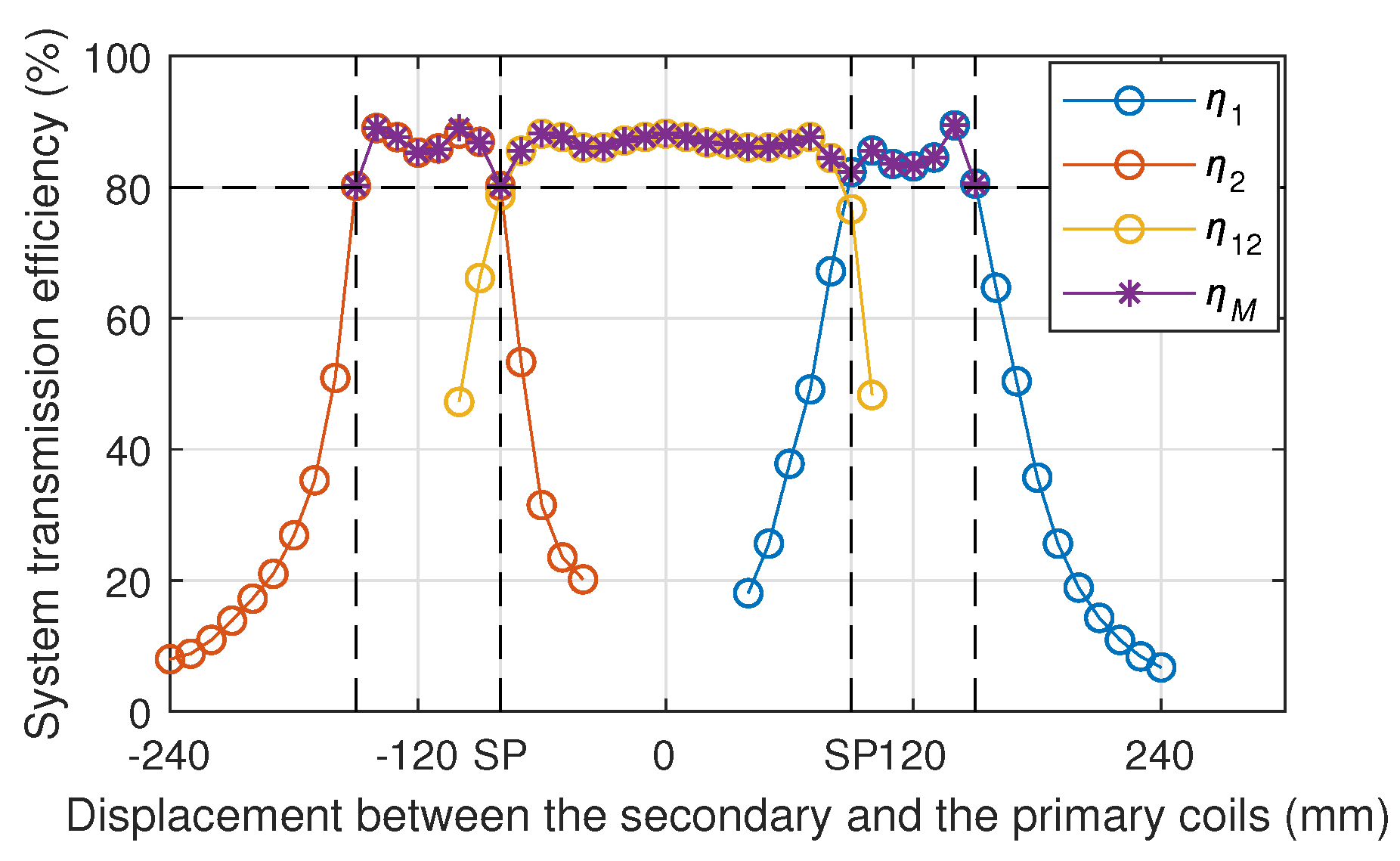
Figure 11 shows the experimental results of the transmission efficiency of the two-to-one WPT system. For the case where only a single primary coil works, the system efficiencies of the 1st and 2nd primary coils working separately are denoted as
and
, respectively. When the two primary coils work at the same time, the system efficiency is
. For the adaptive working mode, the system efficiency is
. The experimental results in
Figure 11 show that when the EVs or RVs are positioned at any point in the range of −150 mm to 150 mm, the power transmission efficiency of the system is not less than 80%, and in fact it is greater than 85% in most areas. Although the experimental result of the transmission efficiency is slightly lower than the simulation, the trend of the experimental result is similar to the simulation result.
5. Conclusions
In the paper, a many-to-one WPT wireless charging anti-offset system suitable for high-voltage applications is proposed. In order to achieve the purpose of high-voltage input, the design of inverter series input is adopted, and a multi-winding transformer is equipped to solve the power integration problem when multiple inverters are running at the same time. In order to realize the many-to-one transmission of the WPT system, the multi-winding transformer is also used to solve the problem of distributing power to each primary loop. This paper uses the method of circuit analysis to study the power transmission characteristics of multiple primary coils in the multi-to-one WPT topology, and designs a system containing two inverters and two primary loops for simulation and verification. In order to realize the purpose of anti-offset in wireless charging of the EVs or RVs, an adaptive working mode of many-to-one WPT system is proposed. In this mode, by adding the primary coil, the wireless charging positioning range of the EVs or RVs can be arbitrarily expanded, thereby effectively improving the anti-offset ability of the system. Under the parameters given in this article, simulations and experiments show that in the adaptive working mode, the two primary coils can expand the positioning range to more than four times that of a single primary coil (70 mm to 310 mm).


 ,
, 


