Abstract
Beam-scanning antennas are employed in a wide range of applications, such as in satellite communications and 5G networks. Current commercial solutions rely mostly on electronically reconfigurable phased arrays, which require complex feeding networks and are affected by high losses, high costs, and are often power-hungry. In this paper, a novel beam scanning architecture employing a pair of planar metasurfaces, for use in thin reconfigurable antennas, is presented and experimentally demonstrated. The structure consisted of a radiative passive (non-reconfigurable) modulated metasurface, and a second metasurface that controls beam pointing, operating as a variable-impedance ground plane. Unlike other existing approaches, surface impedance variation was obtained by on-plane varactor diodes, no vias and a single voltage bias. This paper presents a design procedure based on an approximate theoretical model and simulation verification; a prototype of the designed antenna was fabricated for operation in X band, and a good agreement between measured results and simulations was observed. In the presented simple embodiment of the concept, the angular scanning range was limited to ; this limitation is discussed in view of future applications.
1. Introduction
In recent years, reconfigurable antennas have been the subject of constantly growing interest, since beam steering is required in a wide range of present, emerging, and future applications, as in satellite communications, radars, 5G, and beyond-5G networks [1,2,3].
Commercial solutions, current and under development, rely mostly on electronically reconfigurable phased arrays, but the inherent complex feeding networks and high losses make these antennas less than optimal [4]; this has prompted research into alternative architectures. Among these, solutions are favored in which the radiating part and the power distribution structure coexist; the interplay between wave guiding (spatial power distribution) and radiation is well-captured by the leaky-wave paradigm [5,6,7], which allows for approximate designs. Beam steering at a fixed frequency has been achieved using materials with tunable electric properties [8,9,10,11], performed electromechanically [12] or by employing a multitude of (lumped) active components such as varactors [4,13,14,15,16,17,18].
In [18], varactors were used to individually load the grooves of a corrugated microstrip line, with operation below 6 GHz; the resulting antenna was thin and simple but the use of (TEM) microstrip guiding likely affected operation at higher frequencies because of the intrinsic losses. In [14], varactors were employed as tuning elements for a high-impedance surface in a 1D Fabry–Perot leaky-waveguide; the inherent transverse resonance mechanism required a thickness of about 3/4 wavelength. In [4], varactors were inserted into tunable-impedance phase-shifting side walls in a waveguide antenna (a modified WR90) derived from a standard waveguide slot array (in leaky-wave operation mode).
One of the most recent uses of metasurfaces is as refracting or reflective intelligent surfaces [19,20,21], also beamformers [22] for satellite-terrestrial networks have been revamped.
In this paper, a novel fixed-frequency beam scanning mechanism is introduced and demonstrated. The main goal of the present study was to investigate the potential of beam steering via distributed varactor diodes with a single DC control, i.e., on-plane varactors and no vias: this can be realized with existing standard low-cost technologies (e.g., pick-and-place). Using the metasurface paradigm, varactors can act as variable (reactive) loads in a suitably designed texture, yielding a variable impedance surface, with a surface impedance value controlled by the DC bias.
By combining a modulated upper metasurface (responsible for radiation) with a reconfigurable impedance plane (responsible for beam scanning), we effectively separated RF wave propagation from DC bias, while maintaining a very small form factor.
In this paper, Section 2 illustrates the adopted design techniques and describes the geometry of the designed antenna, while simulation results and experimental measurements of the fabricated prototype are reported in Section 3. In Section 4, these results are discussed and future work is outlined. Finally, conclusions are drawn in Section 5.
2. Materials and Methods
2.1. Principle of Operation
The beam scanning mechanism was conceived as a dual metasurface structure (see Figure 1a). Radiation is effected by a (static) transparent metasurface with metal texture on a dielectric (inspired by [23]); in a fixed-beam configuration, the radiating metasurface would be backed by a metal plane providing wave guiding. Here, the ground plane was replaced by a tunable-impedance metasurface. The principle of operation was based on the radiation of a guided wave, whose phase velocity was controlled by the variable-impedance surface.
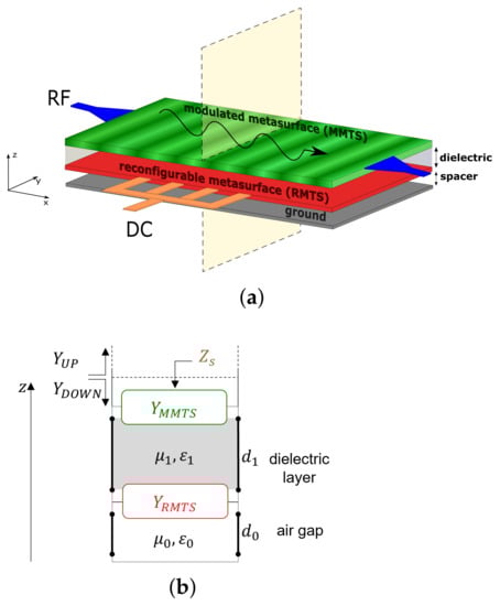
Figure 1.
Structure of the proposed antenna. (a) Schematic architecture. (b) Transverse equivalent network: is the admittance of the upper metasurface, is the admittance of the lower (reconfigurable) metasurface, is the thickness of the dielectric layer, indicates the air gap, and are the admittances looking up and down from the interface between the antenna and free space, is the equivalent impenetrable surface impedance that approximates the whole multilayer structure.
The present study considered an antenna with scan in the vertical plane; the transverse size can range from small to multi-wavelength, depending on the type of feeding structure. For the sake of simplicity, here the intermediate size of one wavelength was considered, which would allow for star-type 2D scanning [24].
Radiation of a guided mode is conveniently framed in the leaky-wave paradigm; hence, radiation happens via the spatially-modulated upper metasurface, exploiting both well-known results [5] and recent advances in metasurface antennas [23]. The operation principle, and thus the first-pass design, can be conveniently understood for the simplest modulation of the radiating metasurface, i.e., for the sinusoidal one [23]:
where is the equivalent impenetrable surface impedance that approximates the whole multilayer structure and takes into account the effects of both metasurfaces (Figure 1b), x is the coordinate along the direction of wave propagation, M is the modulation index, p is the modulation period, and is the average surface reactance.
In this case, leaky-wave radiation happens for the Floquet harmonic of the traveling wave [5,23]; for TM mode propagation, the radiation angle is linked to the average surface reactance by the approximate expression [18,23]:
where , are the free-space impedance and wavenumber, respectively.
2.2. Design Method
The design was carried out in terms of standard guided-mode analysis [25] via the Transverse-Resonance Equation (TRE). As depicted in Figure 1b, the total admittance from the antenna-free space boundary was controlled by the variable impedance layer, resulting in a controllable wavenumber of the guided wave.
The use of the usual “adiabatic” approximation for slow variations of the top impedance allowed us to approximate the antenna with a transverse equivalent network (TEN) (see Figure 1b) at any given sample point of the modulated structure. From this transmission-line representation of the structure, the local value of the surface impedance can be retrieved by solving the corresponding TRE:
where and are the admittances looking up and down from a reference plane located at the interface between the antenna and free space. Indicating with the thickness of the dielectric layer between the two metasurfaces and with the air gap between reconfigurable metasurface and ground plane, standard transmission-line theory yields [26]:
where is the admittance of the upper metasurface, is the admittance of the lower (reconfigurable) metasurface, and is the admittance of the equivalent ground plane looking down from just above the tunable impedance plane (Figure 1b). In (4)–(), and are the TM wave admittances in free space and dielectric substrate:
where and are the wavenumbers in the transverse direction:
and is the longitudinal wavenumber. From (5) and (6), it can be seen that the solution of the TRE depends on the sheet admittances of both metasurfaces ( and ). Since all quantities in (4)–(6) can be expressed as a function of , it is possible to solve (3) for and then obtain the (local) surface impedance as:
It is worth noting that the longitudinal wavenumber considered above is used only to compute the local surface impedance based on the adiabatic approximation, and does not correspond to the actual wavenumber of the leaky wave that arises from the modulation of such impedance.
The average value of is linked to the radiation angle through (2). This means that tuning directly affects the beam direction, thus validating the concept of this architecture. Once a desired radiation angle for the harmonic is chosen, the modulation period p is retrieved from (2) after selecting a proper value of among those physically attainable with the considered structure.
The design process now requires the choice of the geometry of both metasurfaces and the computation of their sheet admittances and , in order to solve (3). For the upper layer, a unit cell was chosen such that its admittance can be easily modulated by varying only one geometric feature, e.g., the gap width between two adjacent metal strips, as in [23]. For the implementation of the tunable metasurface, the unit cell shown in Figure 2 was used. This shape was inspired by the geometry described in [27]. Each unit cell contained two MAVR-011020-1411 varactors that were approximated as RC series elements for simulation purposes; the values of resistance and voltage-dependent capacitance were taken from the manufacturer’s datasheet [28]. Varying the bias voltage changes the varactors’ capacitance, which in turn affects the sheet admittance of this layer.
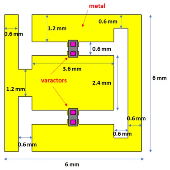
Figure 2.
Unit cell of the reconfigurable metasurface.
The computation of must be carried out for every possible value of the gap width in the constitutive unit cell, while must be determined for every possible biasing state of the varactor diodes. This allowed us to obtain the equivalent impenetrable surface reactance by solving the TRE for every combination of gap width in the upper metasurface and capacitance value in the reconfigurable plane. Moreover, at any given frequency, both admittances are also dependent on the longitudinal wavenumber [14,29]: namely, and , where g and C are the gap width and the varactors’ capacitance, respectively. Therefore, to compute such admittances, the technique described in [14,30] was adopted, where the dependence on the longitudinal wavenumber was retrieved by performing scattering simulations of the constitutive unit cells for different angles of incidence. In particular, similarly to what was carried out in [30], the rational functions used to express and are:
In (12) and (13), subscripts z and p indicate zeros and poles of the rational functions. These quantities are expressed as third degree polynomials of . In the frequency range of interest ([10.55–10.75] GHz), for the considered geometries, is capacitive and is always inductive.
Figure 3 shows how the surface reactance of the whole antenna is affected by a change in the varactors’ bias voltage. The curve relating to the gap width is shifted when the bias voltage goes from 0 V to 8.2 V. This means that, for a fixed spatial modulation in the upper layer, the sinusoidal profile of the surface reactance (and its average value ) seen by the traveling wave is dependent on the varactors’ basing state. Since is linked to the radiation angle through (2) and the period p is fixed by the upper metasurface, beam steering occurs.
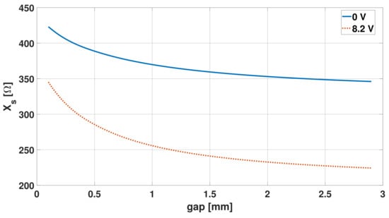
Figure 3.
Surface reactance of the whole structure vs gap width in the array of strips, for two different values of the varactors’ bias voltage.
2.3. Implementation
A center-band frequency of 10.65 GHz was considered. A Rogers RT5880 () 3.175 mm-thick substrate was placed between the upper radiating layer and the lower variable-impedance plane. The unit cell of the modulated metasurface was chosen to be about 1/10 of the wavelength, i.e., 3 mm. The air gap between the reconfigurable plane and the ground was set to 1.5 mm in order to allow enough space for the varactors.
The modulation period p of the top impedance surface was computed from (2), setting a radiation angle of for a 0 V bias voltage of the varactors, and this resulted in mm. Since the unit cell of the modulated metasurface was 3 mm wide, the cosinusoidal variation of the reactance in one period was sampled in nine points, i.e., with sufficient sampling. For the radiating part, eight modulation periods were chosen for a total length of 216 mm; this was a good compromise between beam width and (leaky-wave) tapering and, at any rate, yielding low towards the matched load.
The bias scheme of the varactors in the variable-impedance plane is depicted in Figure 4, which shows an alternate-potential scheme. The necessary single DC bias was conveyed by two 0.15 mm-wide buses placed at the opposite sides of the metasurface; the RF reactance of the very thin (high-impedance) lines was considered enough to decouple RF and DC without the need for a filter, and that was confirmed by simulations.
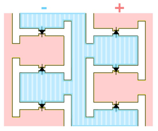
Figure 4.
DC voltage distribution in the reconfigurable metasurface.
The resulting complete structure of the designed antenna is shown in Figure 5. The upper modulated metasurface is depicted in Figure 5a, while Figure 5c shows the lower reconfigurable impedance plane; the vertical stackup of the antenna can be seen in Figure 5b. The overall thickness of the structure was less than at the working frequency of 10.65 GHz, resulting in a very small form factor. It should be noted from Figure 6 that the unit cell of the reconfigurable metasurface was twice as large as that of the upper layer, in order to reduce the total number of varactors needed in the structure, which amounted to 360.
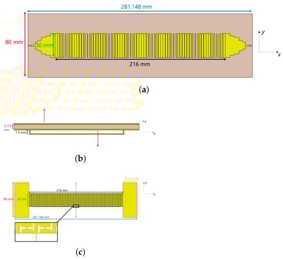
Figure 5.
Complete model of the designed antenna. (a) Upper sinusoidally modulated reactance surface. (b) Lateral view of the antenna. (c) Reconfigurable plane; the inset shows one of the two DC buses.
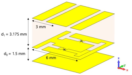
Figure 6.
Unit cell of the fully-stacked structure.
The excitation was provided with a 50 Ohm coaxial cable, which was matched to the antenna by a properly designed tapered section (Figure 5a).
3. Results
Full-wave simulations of the designed antenna were performed with the commercial software CST Studio Suite [31]. The varactor diodes were used in a 0–8.2 V biasing range and their capacitance went from 0.233 pF to 0.0548 pF, according to the manufacturer’s datasheet [28]. The beam pointing angles obtained from these simulations at the working frequency of 10.65 GHz are listed in Table 1, showing excellent agreement with the main beam directions computed using the approximate model described in Section 2.2.

Table 1.
Calculated, simulated, and measured radiation angles at GHz.
A prototype was fabricated and tested (Figure 7). The modulated metasurface and the reconfigurable plane are pictured in Figure 7a,b, while Figure 7c,d show the tapered feeding section on the upper layer and the varactor diodes soldered in the lower metasurface, respectively. Radiation measurements were performed in an NF-FF spherical range; the full radiation pattern was obtained, allowing evaluation of directivity and radiation efficiency.
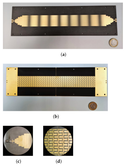
Figure 7.
Fabricated antenna prototype. (a) Top modulated metasurface. (b) Reconfigurable impedance plane. (c) Coaxial cable and matched tapered input section at the left end of the upper metasurface (same tapered section is present at the opposite end). (d) Zoom showing the soldered varactors in the lower reconfigurable metasurface.
Measured far-field patterns at GHz for different bias voltages are shown in Figure 8, together with the simulation results, which are in excellent agreement.
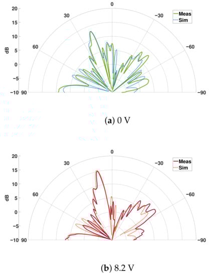
Figure 8.
Measured and simulated radiation pattern in the E-plane at GHz for different values of bias voltage.
The antenna gain bandwidth was 200 MHz around the working frequency of GHz; the impedance bandwidth was larger than the gain one. The scattering parameters and of the fabricated prototype are shown in Figure 9: was always below −10 dB in the working band for all varactors’ bias voltages, while remained below −20 dB, which is very important for the efficiency of a traveling-wave antenna.
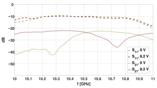
Figure 9.
Measured and for two different values of bias voltage.
In the considered frequency range, the gain spanned from dB to dB with varying bias voltage, while the radiation efficiency was between and . The measured aperture efficiency went from to .
In Figure 8, a side-lobe is noticeable in the backward radiation direction; this lobe can be ascribed to radiation of the harmonic, which falls within the fast wave region at the working frequency [23]. These results are consistent with what can be predicted using (2), i.e., the harmonic radiating at about and for a bias voltage equal to 0 V and V, respectively. The radiation pattern also presents an irregular shape and high side-lobes; this can be ascribed to the anisotropy of the impedance planes, in particular of the lower reconfigurable metasurface. In fact, its unit cell geometry and the placement of the varactor diodes inside it are such that a change in the bias voltage alters not only the component of the sheet impedance in the direction of wave propagation, but also the transverse one. This may cause disturbances in the wave propagation.
4. Discussion
In Table 2, the performances of the antenna described in this paper are compared to those of other solutions found in the literature. In the table, “efficiency” stands for radiation efficiency.
Table 2.
Comparison with other LWAs found in the literature.
Radiation efficiency and gain values are comparable to those reported in the other works (above the average). The comparison is conservative because all reported references work at a lower frequency, which inherently entails lower losses. The small form factor, simple biasing and high efficiency make the proposed architecture interesting for several low-profile applications. The angular scanning range achieved with this first prototype is, on the other hand, limited: improvement of this is thus important and the subject of current work. Here, some of the reasons for this limitation are listed and ways to improve it are proposed.
A possible degree of improvement is represented by the choice of the dielectric substrate and its thickness, especially for the side lobes. In particular, a higher relative permittivity results in a wider range of surface reactance values, , which allows for a larger modulation factor M and, consequently, a higher leakage constant [23]. This in turn translates into the reduction of side-lobes.
Figure 10 shows the simulated radiation pattern at GHz for an alternative design of the proposed antenna, featuring a Rogers RO3006 substrate () of a thickness equal to mm: the radiation angle steers from to when the bias voltage goes from 0 V to V. In this case, no other harmonic beside the radiates, and the very small backward-directed side-lobes are due to the spurious radiation of a second, higher-order TM mode. Directivity values are the same as in the previous configuration. A further reduction of side-lobes could be obtained by tapering the modulation index M along the length of the antenna [32], which was not pursued here.
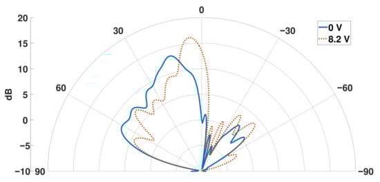
Figure 10.
Simulated radiation pattern at GHz for different bias voltages for an alternative design with Rogers RO3006 substrate ().
Another margin of improvement involves the geometry of the reconfigurable metasurface’s unit cell. The tunable unit cell used in this first prototype was inspired by the literature and had a different original use [27]; a new geometry could be devised to obtain a wider impedance range for the same diodes.
Moreover, the design presented in this paper was based on the combination of a capacitive impedance (top) and an inductive one (bottom), and the propagation of the TM mode. However, different combinations of impedances can be employed (e.g., capacitive-capacitive) that may increase the scanning range if properly designed, especially if a dielectric material with higher electric permittivity is used. In particular, analyses carried out with the approximate analytical model show that use of the TE mode (instead of the TM) yields a much larger steering range. This possibility is currently being studied and will be the subject of future work (excitation of the TE mode is less natural than that of the TM).
Finally, the radiating surface employs the standard sinusoidal modulation scheme; the scan range can be improved (for the same impedance variation of the bottom plane) by more advanced impedance modulation schemes, and especially by ad-hoc numerical optimization of the profile [33,34]; this has shown the potential of increasing sensitivity to phase velocity, thus enhancing the scanning range.
5. Conclusions
In this work, a novel beam steering configuration with varactor diodes, a single voltage bias, and no bias has been demonstrated. The small form factor, simple biasing, and high efficiency make the proposed architecture interesting for low-profile applications. The angular scanning range achieved with this first prototype is limited, but several ways to improve it were discussed.
Author Contributions
Conceptualization, G.V.; methodology, L.T. and F.V.; software, L.T.; validation, L.T., F.V., G.G. and R.G.; formal analysis, L.T. and F.V.; investigation, L.T., F.V. and G.G.; resources, G.G. and G.V.; data curation, L.T. and R.G.; writing—original draft preparation, L.T.; writing—review and editing, G.G., R.G. and G.V.; visualization, L.T., G.G. and R.G.; supervision, G.V.; project administration, G.V.; funding acquisition, G.V. All authors have read and agreed to the published version of the manuscript.
Funding
This work was supported by the Italian Ministry of Research PRIN 2017S29ZLA “Metasurface Antennas for Space Applications”.
Institutional Review Board Statement
Not applicable.
Informed Consent Statement
Not applicable.
Data Availability Statement
Not applicable.
Acknowledgments
The authors would like to acknowledge the invaluable help and the technological skill provided by Giuseppe Franco (Fondazione LINKS) in the realization of the prototype.
Conflicts of Interest
The authors declare no conflict of interest.
References
- Christodoulou, C.G.; Tawk, Y.; Lane, S.A.; Erwin, S.R. Reconfigurable Antennas for Wireless and Space Applications. Proc. IEEE 2012, 100, 2250–2261. [Google Scholar] [CrossRef]
- Schoebel, J.; Buck, T.; Reimann, M.; Ulm, M.; Schneider, M.; Jourdain, A.; Carchon, G.; Tilmans, H. Design Considerations and Technology Assessment of Phased-Array Antenna Systems with RF MEMS for Automotive Radar Applications. IEEE Trans. Microw. Theory Tech. 2005, 53, 1968–1975. [Google Scholar] [CrossRef]
- Huang, K.C.; Wang, Z. Millimeter-Wave Circular Polarized Beam-Steering Antenna Array for Gigabit Wireless Communications. IEEE Trans. Antennas Propag. 2006, 54, 743–746. [Google Scholar] [CrossRef]
- Ohadi, A.; Eleftheriades, G.V. Fixed-Frequency Beam-Steering Using Slotted Waveguide With Tunable Impedance Walls. IEEE Open J. Antennas Propag. 2021, 2, 978–990. [Google Scholar] [CrossRef]
- Oliner, A.; Hessel, A. Guided Waves on Sinusoidally-Modulated Reactance Surfaces. IRE Trans. Antennas Propag. 1959, 7, 201–208. [Google Scholar] [CrossRef]
- Jackson, D.R.; Caloz, C.; Itoh, T. Leaky-Wave Antennas. Proc. IEEE 2012, 100, 2194–2206. [Google Scholar] [CrossRef]
- Monticone, F.; Alu, A. Leaky-Wave Theory, Techniques, and Applications: From Microwaves to Visible Frequencies. Proc. IEEE 2015, 103, 793–821. [Google Scholar] [CrossRef]
- Esquius-Morote, M.; Gómez-Díaz, J.S.; Perruisseau-Carrier, J. Sinusoidally Modulated Graphene Leaky-Wave Antenna for Electronic Beamscanning at THz. IEEE Trans. Terahertz Sci. Technol. 2014, 4, 116–122. [Google Scholar] [CrossRef]
- Torabi, E.; Rozhkova, A.; Chen, P.Y.; Erricolo, D. Compact and Reconfigurable Leaky Wave Antenna Based on a Tunable Substrate Integrated Embedded Metasurface. In Proceedings of the 2020 IEEE International Symposium on Antennas and Propagation and North American Radio Science Meeting, Montréal, QC, Canada, 5–10 July 2020; pp. 163–164. [Google Scholar] [CrossRef]
- Martini, E.; Pavone, S.; Albani, M.; Maci, S.; Martorelli, V.; Giodanengo, G.; Ferraro, A.; Beccherelli, R.; Toso, G.; Vecchi, G. Reconfigurable Antenna Based on Liquid Crystals for Continuous Beam Scanning with a Single Control. In Proceedings of the 2019 IEEE International Symposium on Antennas and Propagation and USNC-URSI Radio Science Meeting, Atlanta, GA, USA, 7–12 July 2019; pp. 449–450. [Google Scholar] [CrossRef]
- Pavone, S.C.; Martini, E.; Caminita, F.; Albani, M.; Maci, S. Surface Wave Dispersion for a Tunable Grounded Liquid Crystal Substrate Without and With Metasurface on Top. IEEE Trans. Antennas Propag. 2017, 65, 3540–3548. [Google Scholar] [CrossRef]
- Rabbani, M.S.; Churm, J.; Feresidis, A.P. Continuous Beam-Steering Low-Loss Millimeter-Wave Antenna Based on a Piezo-Electrically Actuated Metasurface. IEEE Trans. Antennas Propag. 2022, 70, 2439–2449. [Google Scholar] [CrossRef]
- Sievenpiper, D. Forward and Backward Leaky Wave Radiation with Large Effective Aperture from an Electronically Tunable Textured Surface. IEEE Trans. Antennas Propag. 2005, 53, 236–247. [Google Scholar] [CrossRef]
- Guzman-Quiros, R.; Gomez-Tornero, J.L.; Weily, A.R.; Guo, Y.J. Electronically Steerable 1-D Fabry-Perot Leaky-Wave Antenna Employing a Tunable High Impedance Surface. IEEE Trans. Antennas Propag. 2012, 60, 5046–5055. [Google Scholar] [CrossRef]
- Gregoire, D.J.; Patel, A.; Quarfoth, R. A Design for an Electronically-Steerable Holographic Antenna with Polarization Control. In Proceedings of the 2015 IEEE International Symposium on Antennas and Propagation & USNC/URSI National Radio Science Meeting, Vancouver, BC, Canada, 19–25 July 2015; pp. 2203–2204. [Google Scholar] [CrossRef]
- Quarfoth, R.G.; Patel, A.M.; Gregoire, D.J. Ka-Band Electronically Scanned Artificial Impedance Surface Antenna. In Proceedings of the 2016 IEEE International Symposium on Antennas and Propagation (APSURSI), Fajardo, PR, USA, 26 June–1 July 2016; pp. 651–652. [Google Scholar] [CrossRef]
- Shlezinger, N.; Alexandropoulos, G.C.; Imani, M.F.; Eldar, Y.C.; Smith, D.R. Dynamic Metasurface Antennas for 6G Extreme Massive MIMO Communications. IEEE Wirel. Commun. 2021, 28, 106–113. [Google Scholar] [CrossRef]
- Wang, M.; Ma, H.F.; Tang, W.; Zhang, H.C.; Jiang, W.; Cui, T.J. A Dual-Band Electronic-Scanning Leaky-Wave Antenna Based on a Corrugated Microstrip Line. IEEE Trans. Antennas Propag. 2019, 67, 3433–3438. [Google Scholar] [CrossRef]
- Lin, Z.; Niu, H.; An, K.; Wang, Y.; Zheng, G.; Chatzinotas, S.; Hu, Y. Refracting RIS-Aided Hybrid Satellite-Terrestrial Relay Networks: Joint Beamforming Design and Optimization. IEEE Trans. Aerosp. Electron. Syst. 2022, 58, 3717–3724. [Google Scholar] [CrossRef]
- Niu, H.; Lin, Z.; An, K.; Wang, J.; Zheng, G.; Al-Dhahir, N.; Wong, K.K. Active RIS Assisted Rate-Splitting Multiple Access Network: Spectral and Energy Efficiency Tradeoff. IEEE J. Sel. Areas Commun. 2023. [Google Scholar] [CrossRef]
- Niu, H.; Lin, Z.; Chu, Z.; Zhu, Z.; Xiao, P.; Nguyen, H.X.; Lee, I.; Al-Dhahir, N. Joint Beamforming Design for Secure RIS-Assisted IoT Networks. IEEE Internet Things J. 2023, 10, 1628–1641. [Google Scholar] [CrossRef]
- Lin, Z.; Lin, M.; Champagne, B.; Zhu, W.P.; Al-Dhahir, N. Secrecy-Energy Efficient Hybrid Beamforming for Satellite-Terrestrial Integrated Networks. IEEE Trans. Commun. 2021, 69, 6345–6360. [Google Scholar] [CrossRef]
- Patel, A.M.; Grbic, A. A Printed Leaky-Wave Antenna Based on a Sinusoidally-Modulated Reactance Surface. IEEE Trans. Antennas Propag. 2011, 59, 2087–2096. [Google Scholar] [CrossRef]
- Martinez-Ros, A.J.; Gomez-Tornero, J.L.; Goussetis, G. Broadside Radiation from Radial Arrays of Substrate Integrated Leaky-Wave Antennas. In Proceedings of the 2012 6th European Conference on Antennas and Propagation (EUCAP), Prague, Czech Republic, 26–30 March 2012; pp. 252–254. [Google Scholar] [CrossRef]
- Walter, C. Traveling Wave Antennas; McGraw-Hill: New York, NY, USA, 1965. [Google Scholar]
- Pozar, D.M. Microwave Engineering, 4th ed.; John Wiley & Sons: Hoboken, NJ, USA, 2011. [Google Scholar]
- Wu, Z.; Grbic, A. Serrodyne Frequency Translation Using Time-Modulated Metasurfaces. IEEE Trans. Antennas Propag. 2020, 68, 1599–1606. [Google Scholar] [CrossRef]
- MACOM Technology Solutions. Available online: https://www.macom.com/products/product-detail/MAVR-011020-1411 (accessed on 12 March 2021).
- Maci, S.; Caiazzo, M.; Cucini, A.; Casaletti, M. A Pole-Zero Matching Method for EBG Surfaces Composed of a Dipole FSS Printed on a Grounded Dielectric Slab. IEEE Trans. Antennas Propag. 2005, 53, 70–81. [Google Scholar] [CrossRef]
- Guzmán Quirós, R. Analysis and Design of New Electronically Reconfigurable Periodic Leaky-Wave Antennas. Ph.D. Dissertation, Universidad Politécnica de Cartagena, Cartagena, Spain, 2014. [Google Scholar]
- Dassault Systèmes Simulia. CST Studio Suite 2019. Available online: www.cst.com (accessed on 12 March 2021).
- Yang, D.; Nam, S. Tapered Unit Cell Control of a Sinusoidally Modulated Reactance Surface Antenna. IEEE Antennas Wirel. Propag. Lett. 2018, 17, 2479–2483. [Google Scholar] [CrossRef]
- Vernì, F. Advanced Computational Electromagnetics for Metasurfaces. Ph.D. Dissertation, Politecnico di Torino, Turin, Italy, 2020. [Google Scholar]
- Caminita, F.; Martini, E.; Minatti, G.; Sabbadini, M.; Maci, S. Low-Profile Dual-Polarized Isoflux Antennas for Space Applications. IEEE Trans. Antennas Propag. 2021, 69, 3204–3213. [Google Scholar] [CrossRef]
Disclaimer/Publisher’s Note: The statements, opinions and data contained in all publications are solely those of the individual author(s) and contributor(s) and not of MDPI and/or the editor(s). MDPI and/or the editor(s) disclaim responsibility for any injury to people or property resulting from any ideas, methods, instructions or products referred to in the content. |
© 2023 by the authors. Licensee MDPI, Basel, Switzerland. This article is an open access article distributed under the terms and conditions of the Creative Commons Attribution (CC BY) license (https://creativecommons.org/licenses/by/4.0/).