Abstract
The adaptive iterative learning control method for electro-hydraulic shaking tables based on the complex optimization algorithm was proposed to overcome the potential stability problem of the traditional iteration control method. The system identification precision’s influence on convergence was analyzed. Based on the real optimization theory and the mapping relationship between real vector space and complex vector space, the complex Broyden optimization iterative algorithm was proposed, and its stability and convergence was analyzed. To improve the stability and accelerate the convergence of the proposed algorithm, the complex steepest descent algorithm was proposed to cooperate with the complex Broyden optimization algorithm, which can adaptively optimize the complex steepest gradient iterative gain and update the system impedance in real time during the control process. The shaking tables experiment system was designed, applying xPC target rapid prototype control technology, and a series of experimental tests were performed. The results indicated that the proposed control method can quickly and stably converge to the optimal solution no matter whether the system identification error is small or large, and, thus, verified that validity and feasibility of the proposed adaptive iterative learning method.
1. Introduction
The electro-hydraulic shaking table is the most used and reliable earthquake simulation test equipment in the field of structure anti-seismic research, especially in recent decades [1,2,3]. However, for earthquake experiments with structures with a large span such as trains, bridges and pipelines, etc., a single shaking table is not at all sufficient; thus, a shaking table array system composed of multiple identical or different shaking tables is proposed to solve this problem [4,5,6,7]. The shaking table array is more complex compared with the single shaking table system due to the tracking precision needed and also the synchronization precision needed to protect the test specimen [8]. Usually, the large structure used to carry out earthquake test experiments is very complex and represents obvious nonlinearity, and the shaking table array system also encounters various disturbances, etc., all of which increase the difficulty of the control system and, thus, influence the experiment effect [9,10].
For the shaking table control problem, many experts have devoted much effort to improving the response performance from different perspectives. Guo [11] adopts the latest advances in deep learning to develop a physics-guided long short-term memory network for system identification of the shaking table. Huang [12] analyzed the coupling phenomena and reasons for the multiaxis hydraulic servo table based on a dynamic model of a multiaxis hydraulic servo shaking table. Li [13] analyzed the effects of the characteristics of the dual shaking tables–specimen interaction on the system performance. Soleymani [14] designed a fuzzy sliding mode supervisory controller for an electric seismic shaking table with variable payload. Zhao [15] proposed modal space three-state feedback and feedforward control to solve the coupling problem. Cheng [16] proposed a control algorithm based on the frequency-domain filtered-x least mean square adaptive algorithm to achieve power spectral density replication.
How to improve the control performance of shaking tables with system nonlinearity and parametric uncertainty has been of great interest. Yang [11] proposed a combined controller with ultra-local model principle-based adaptive SMC to improve the swept-sine control precision of an electro-hydraulic shaking table considering the nonlinearities, uncertainties and unexpected disturbance. In [12], an adaptive dynamic surface control method with nonlinear disturbance observers was proposed to improve the tracking precision of an electro-hydraulic shaking table with unknown time-varying disturbances. To obtain a good acceleration replication effect for a hydraulic shaking table, a feed-forward inverse model controller based on the RELS algorithm was proposed by Shen [13]. In [14], a novel stochastic gradient algorithm was presented to estimate the harmonic information of a hydraulic shaking table. Giacomo [15] compared the results of two tests of automotive parts, respectively using a single-axis shaker and a three-axis shaker, which indicated that the MIMO control scheme had a better control effect. In [16], an acceleration waveform replication scheme combining an offline feed-forward compensator with an online adaptive controller was proposed to improve the control performance of a hydraulic shaking table.
The offline iterative control method was proposed for the electro-hydraulic shaking tables system, and has been become the most widely and successfully applied compensation control method. Offline iterative control is an incausal feedforward control technique based on the inverse model of the system linear frequency model. Offline iterative control can realize the non-minimum phase system to obtain very high precision, which is unrealizable using the real-time feedforward control method. In 1976, Cryer first proposed the offline iterative control method and applied this technique to the road’s waveform replication of a four-channel road simulator [17]. In 1977, MTS introduced the remote parameter control technique to an electro-hydraulic shaking table control system [18]. Plummer reviewed and summarized the development history of the offline iterative control technique, and indicated its two main applications: vehicle experiments and seismic experiments [19]. Underwood researched the application of the iterative control technique in random, sine and shock vibration experiment in depth [20]. Bladh [21] carried out a virtual vehicle persistence vibration test combining offline iterative control and a vehicle software model. Eksteen [22] applied offline iterative control based on the nonlinear inverse model to time domain waveform replication. Yang [23] realized acceleration time domain waveform replication using offline iterative control based on singular value threshold control.
The traditional iterative control mentioned above usually adopts the same small iterative gain to ensure the system is stable, which reduces the convergence efficiency and requires more iterative times to obtain high control precision. Liu [24] proposed adaptive variable gain iterative control based on the frequency Fx-LMS algorithm and applied it to a shock vibration test. Cornelis [25] improved traditional offline iterative control, increasing the identification precision by using the optimal exciting signals and introducing a weighting correction factor to update system frequency response function. Moten [26] combined adaptive inverse control and offline iterative control to improve the control precision and convergence efficiency of shaking tables’ time domain waveform replication. Cuyper [27] proposed hybrid control, combining offline iterative control and a real-time feedback controller based on H∞ robust control. Tang [28] proposed inner model control combined with offline iterative control to improve the iterative convergence and control precision.
Aiming at the phenomenon that a nonlinear mechanical system may be a non-minimum phase system and the system can be non-convergent using traditional iterative control, Smolders [29] proposed nonlinear iterative control based on the Newton optimization algorithm to improve the control precision and convergence speed of a four-channel road simulator. Daley [30] applied iterative control based on the gradient optimization algorithm to a road simulator to reduce the iterative times and improve the system robustness. Underwood [31] adopted the quasi-Newton optimization algorithm to update system impedance and iterative gain to realize sine sweep adaptive iterative control. Yang [32] proposed a single sine sweep control method based on the extended quasi-Newton optimization algorithm to correct system FRF to solve the potential stability problem.
Roberts [33] proposed iterative control based on the Broyden optimization algorithm and analyzed the global convergence to solve the slow convergence problem of simulation test equipment using traditional iterative control. Gunnarsson [34] proposed the frequency domain optimization iterative learning control method to solve the problem of minimizing the control error of a nonlinear system. Adali [35] researched the equivalence relation of the optimization algorithm in a real domain and a complex domain and the advantage in the complex domain, and then applied the complex domain optimization algorithm to the nonlinear function of signal processing. Brandwood [36] proposed an optimization algorithm based on a complex vector gradient operator to solve the real valve scalar optimization of the complex vector function. Hjorungnes [37] studied the complex domain optimization iterative algorithm and its application in signal processing. Kreutzdelgado [38] deduced the gradient operator and related complex differential algorithm in a complex domain. Sorber [39] studied the unconstrained optimization algorithm of complex vector real valve function and its related theory.
This paper presents a novel adaptive iterative control method based on the complex domain optimization algorithm to improve the system convergence rate and system stability. The complex domain quasi-Newton optimization algorithm is deduced based on the real domain quasi-Newton optimization algorithm. The complex steepest gradient iterative gain is proposed to obtain a better convergence rate, which can better compensate the phase error of the control system. The proposed adaptive iterative control can make the system stable even if the identified system model error is quite large, and make the system converge to the desired signal more quickly than the traditional iterative control. The proposed method can be introduced to the shaking tables system to efficiently realize the precise acceleration time domain waveform replication.
The remainder of this paper is organized as follows. Section 2 presents the investigated electro-hydraulic shaking tables system and the basic principle of the shaking tables’ traditional iterative control method. In Section 3, the proposed complex domain adaptive iterative control scheme is introduced. Section 4 shows the application of the proposed complex domain optimization algorithm to shaking tables’ adaptive iterative control. Experiments are carried out to validate the performance of the designed control method in Section 5, followed by Section 6, which briefly concludes the paper.
2. Offline Iteration Learning Control for Shaking Tables System
2.1. The Researched Shaking Tables System
The shaking tables system researched in this paper has two electro-hydraulic shaking tables, which are shown in Figure 1. The large-span structure test specimen is fixed on the two platforms. Each shaking table has eight servo valves, eight hydraulic cylinders, eight displacement sensors, eight accelerator sensors, one upper platform and one lower platform fixed in the base. Both the shaking tables can realize six DOF motions. Each hydraulic cylinder has one upper hinge connected with the upper platform and one lower hinge connected with the lower platform. The control system sends the control command to the servo valves, and then causes the hydraulic cylinder to move, then the upper platform drive test specimen to move according to the expected trajectory. Meanwhile, the feedback displacement and acceleration information is translated to the control system in real time to compensate the control signal.

Figure 1.
The electro-hydraulic shaking tables.
2.2. Offline Iterative Learning Control for Shaking Tables
The traditional offline iterative learning control method for shaking tables is shown in Figure 2. It can be seen that the total process is mainly composed of three phases: experiment preparation, which includes experiment data preprocessing, software launch and the preparation of the hydraulic power supply and hardware equipment; system model identification, which builds the linear system FRF model and then computes the inverse model; and target simulation, which iteratively computes the driven signal according to identified FRF model and desired target signal.
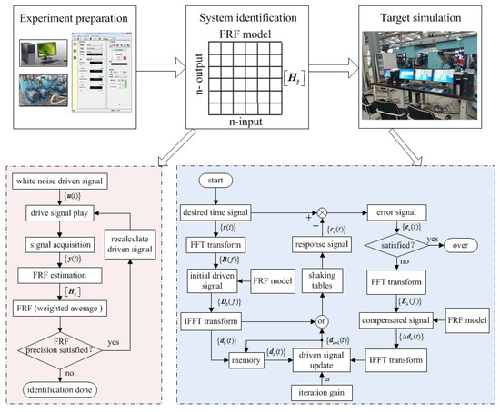
Figure 2.
Offline iterative learning control schematic for shaking tables.
Generally, the input signal of the identified system is accurately known, so the system identification method usually applies the H1 identification method to evaluate the system FRF model:
where is the self-spectrum matrix of the input signal and is the cross-spectrum matrix of the input signal and output signal.
The process of the target simulation stage is as follows:
(1). Apply FFT to the time domain reference signal to obtain the frequency domain reference signal , compute the driven signal in the frequency domain according to the identified system FRF model , then carry out IFFT to obtain the original time domain driven signal :
(2). Excite the system with , acquire the response signal and compute the control error signal :
(3). Determine whether meets the precision requirement. If the condition is met, the iterative process will terminate; if the condition is not met, carry out FFT to and compute the frequency domain compensated driven signal :
(4). Carry out IFFT to and compute the 1st iteratively driven signal with iterative gain :
(5). Excite the system with the new driven signal , acquire the response signal and compute the control error signal :
(6). Determine whether meets the precision requirement. If the condition is met, the iterative process will terminate; if the condition is not met, repeat steps (3)~(5). The iterative process will terminate until the control error signal meets the desired precision requirement, where k = 1, 2 ….
2.3. Influence of Identification Precision on Control System
It can be seen from the above that the identified FRF model directly participates in the control process and plays an important role in the control system, so this section will study the influence of system identification precision on offline iterative control. The identified FRF model is just the approximation of the true system due to nonlinearity, uncertainty and identification method error. From this, the simplified iterative process shown in Figure 2 considering the identified FRF model error is shown in Figure 3.
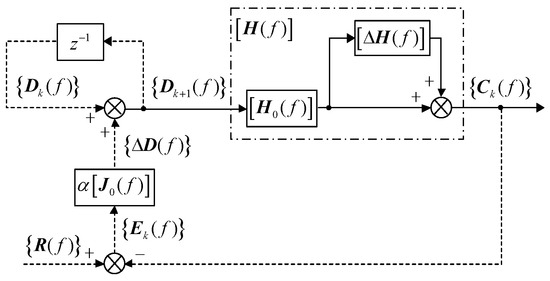
Figure 3.
Offline iterative control schematic considering model error.
In Figure 3, the solid line indicates the real-time control part and the dotted line indicates the offline control part. is the frequency domain reference signal vector, is the kth iterative frequency domain response signal vector, is the kth iterative frequency domain driven signal vector, is the frequency domain compensated driven signal vector, is the true system model, is the identified system model and its inverse model is the impedance matrix and is the model error of and . Thus,
where is the n dimensional unit matrix and n is the dimension of the control system.
From Figure 3, the driven signal update function can be obtained:
Multiplying both sides of Equation (8) by , it can be derived that
Submitting and into Equation (9) yields
From Equation (10), the following can be derived:
From Equation (11), it can be seen that if the norm of control error during the iteration process decreases with the increase in iterative time, then the iterative control is convergent, and the following condition of tending to zero can be expressed as
The equivalent condition of Equation (12) is
From Equation (13), it can be seen that the convergence and convergent rate are determined by the iterative gain and identified FRF error . The iteration process will be unstable if is quite large in some frequency points. As a result, to improve the iterative control performance, the optimal iterative gain needs to be chosen and the identified FRF needs to be updated, which makes the iterative control have a faster convergent rate while keeping the system stable.
3. The Complex Optimization Algorithm-Based Iterative Learning Control
As is mentioned above, to solve problem of offline iterative learning control, it is necessary to adapt different iterative gains in different frequency points. Thus, to obtain a better control effect, the optimal iterative gain and system impedance update are developed during the iteration process. The purpose of iterative control is to minimize the control error . To solve the potential stability and convergence problem of iterative control, this paper proposed an adaptive iterative control based on the complex optimization algorithm, which makes the response signal close to the desired signal to reduce through optimize iterative gain and update system impedance . Due to the fact that the computation is realized in the complex domain, which contains magnitude and phase, this method belongs to complex optimization theory.
The essence of the MIMO iterative control problem for shaking tables is the minimum of the object function described using the L2 norm of control error:
The purpose of iterative control is to find the optimal complex driving signal , which makes Equation (14) the minimum. However, the electro-hydraulic shaking tables system is a typical nonlinear system, which means is nonlinear and is the function of the driving signal . Thus, the problem of this paper can be considered to solve the nonlinear norm function shown in Equation (14), whose optimization is the function of complex vector , so this paper will research the optimization theory in the complex domain.
3.1. The Real Optimization Algorithm Theory
Assuming the dimensions of the input and output signals are both n, the identified system FRF matrix and the corresponding impedance matrix are both n × n complex matrixes. The real domain optimization theory is relatively complete and mature. However, the complex domain optimization algorithm is still incomplete; thus, this paper will research the complex optimization algorithm based on the real optimization algorithm and the mapping relationship between real vector space and complex vector space.
The local unconstrained minimum of nonlinear function in real vector space is given by
where is the n dimension real vector in space and is the nonlinear mapping of .
Assume that is twice continuously differentiable to , then the goal of the optimization problem is to find optimal to minimize the objective function . This problem belongs to optimization theory in real vector space and can be solved by applying the following theorem.
Theorem 1.
Letting be a real valued function defined on a closed and bounded region in ,
(1) if is an inner point of , at which achieves an external value, and if has a continuous first partial derivative, then , that is, the partial derivative of is zero at the optimal vector .
(2) if has a continuous second-order partial derivative in a neighborhood of any inner point of , then for an arbitrary in , there is the quadratic Taylor representation of :
Theorem 1 is the basic principle to solve the unconstrained optimization problem. The common method is using the quadratic function given by Theorem 1(2) and the optimal condition given by Theorem 1(1) to define optimal vector, in which there is , for Equation (15), . At an arbitrary vector near the optimal vector , executing the Taylor series expansion to , then the approximate linear equation is given by
Equation (16) is commonly used to solve the optimization problem by generating a sequence of vectors , which converge to the optimal vector to minimize . The methods used to solve Equation (16) are Newton–Gauss, Newton–Raphson and quasi-Newton, etc. The Newton–Raphson is an efficient algorithm that uses the gradient and Hessian matrix of an objective function to find the minimization sequence. The minimizing sequence is given by the following recursion:
where is the iteration step to minimize and is the Newton direction for the nonlinear optimization problem and is described as
where is the Hessian matrix of to and is the Jacobian matrix of to .
For the Newton iterative optimization method, there is the following local convergence theorem.
Theorem 2.
Let be continuously differentiable in an open convex set . Assume that there is , such that , exists with and . Then, there is an such that for all , the sequence generated by is well defined, converges to and obeys , which is quadratic convergence.
The in Theorem 2 is the gradient of in Equation (2) and the Jacobian of is the Hessian matrix of . Submit into the Newton direction of the nonlinear norm function shown in Equation (17), and it can be obtained that
It can be seen from Equation (18) that is the product of the inverse matrix of the Hessian matrix and the gradient matrix of . If the first item of the Hessian matrix can be ignored, then submit the approximate Hessian matrix into Equation (19), and there is
Submitting Equation (20) into (17), there is the Newton–Gauss optimization algorithm, which has global convergence.
From the above analysis, it can be seen that it is necessary to compute the gradient and Hessian of the function to solve the optimization problem. To simplify this problem, some approximate Secant and Hessian techniques are studied. The most successful approximate method is the Broyden method, whose basic idea is to use an estimate of the Jacobian matrix in Theorem 2 instead of the actual Jacobian matrix, as is shown in following.
Let and , , then there are the following vector and matrix update equations:
It is similar to the Newton–Gauss method, but it uses instead of the Jacobian matrix at . There is a similar global convergence theorem for this method.
Theorem 3.
Let the assumptions in Theorem 2 exist, and there is , which makes and , then sequence generated by Equation (22) converges q-superlinearly to .
If is affine, then the quasi-Newton method given by Equation (22) converges finitely and , that is, this method converges to optimal vector in no more than iterations.
3.2. The Complex Optimization Algorithm
This paper will research the optimization algorithm in complex space and the local unconstrained minimum to nonlinear function given by
where and is holomorphic of .
Let be the complex plane and be continuously differentiable as a function of , then is called the function and its derivative with respect to complex and conjugate complex is, respectively,
Assuming that is holomorphic with respect to each component, then is a holomorphic function. Let and be continuously differentiable, , and , then there is
According to Equation (25), the complex gradient and Hessian matrix with respect to and of function , which is twice continuously differentiable, it can be deduced that
For function , its Taylor series of complex derivatives at complex vector is
Equations (29) and (30) are, respectively, the holomorphic and non-holomorphic Hessian. For , if the non-holomorphic Hessian is positive definite at , then is strictly plurisubharmonic.
Let be open and be strictly plurisubharmonic in , and for , there is , and the following inequation exists:
Equation (32) indicates that when and is strictly plurisubharmonic, there is , , which means has a strict local minimum at .
According to Theorem 2, it can be seen that when the start point is close enough to optimum vector, it can be used to find the optimal complex vector to minimize the second-order approximation iteratively shown in Equation (28). Equation (32) shows that the holomorphic Hessian can be ignored in a neighborhood of optimal vectors, which makes the Newton–Raphson update method for complex vector space.
According to Theorem 1, the complex and conjugate complex gradients vanish if the real gradient vanishes, which is the classic necessary condition that optimal vector must satisfy. Describe using the approximate second order polynomial in Equation (28) ignoring the last item , compute the complex and conjugate complex gradients of Equation (30) and set the results to zero, then the complex Newton–Raphson update algorithm is obtained, which is similar to the real algorithm, in which the update sequence satisfies Equations (33) and (34) and converges to the optimal point.
Assume the holomorphic Hessian of is zero, then there is
According to the mapping relationship of real vector space and complex vector space shown in Equations (24)–(27), and Theorems 1 and 2, the local convergence of the complex vector Newton–Raphson update algorithm shown in Equation (35) can be proven.
The modification to the complex Newton–Raphson algorithm making the algorithm have global convergence is shown in the following:
where is the steepest descent gain to minimize .
Combining Equation (36) with the minimum norm shown in Equation (23), in which is the holomorphic function, the gradient of can be obtained:
The holomorphic and conjugate non-holomorphic Hessian is given by
From Equation (38), it can be seen that the holomorphic Hessian is zero when the holomorphic Hessian of is zero or is zero, or the dot product in Equation (38) is zero. For the iterative control problem of multi-dimension shaking tables shown in Equation (14), can be satisfied at the optimal point of , because is the control error vector, and it is zero at the global optimal vector of .
The analysis above indicates the Broyden method can solve the optimization problem of the nonlinear system well; thus, we will extend the real vector space Broyden method to the complex vector space Broyden.
Let , and , and there is the complex Broyden update algorithm:
The proof of the global convergence of the complex Broyden update algorithm can follow from converting the complex formulation to the real vector formulation and real Broyden method convergence theorem shown in Theorem 3. When is conjugate affine, the complex Broyden method converges to the optimal vector within iterative steps, that is, the algorithm is finitely convergent.
3.3. The Complex Steepest Descent Algorithm
The traditional method for the optimization algorithm is using the positive steepest descent gain to ensure convergence. However, for the complex quasi-Newton method, the complex steepest descent gain would be more satisfactory. Compared with the classical necessary condition at optimal vector , Equation (25) has the simpler necessary condition . To utilize the nature of the optimization problem, the descent condition on the root finding algorithm in the condition is used to obtain the sequence :
The way to ensure that condition (40) satisfied is to use the steepest descent approach. For Equation (39), the necessary condition is
Consider as function of , and describe it with Taylor series, then there is
where .
The complex quantities of the steepest descent condition shown in Equation (41) are
Solve Equation (43), and the steepest descent gain can be obtained:
If the holomorphic Hessian of is approximately zero, Equation (44) is simplified as
According to the optimal iterative step , applying the complex steepest descent, there is
Equation (47) indicates that the complex steepest descent and change in are orthogonal, that is, the complex descent technique produces a monotonically decreasing sequence of values for the objective function.
4. The Adaptive Iteration Learning Control for Shaking Tables
The shaking tables’ iterative driven signal update function shown in Equation (8) is similar to the steepest descent method of the complex Newton–Raphson algorithm, whose object is to minimize the object function
The difference between Equation (8) and traditional iterative control is that the complex matrix and complex error replace the real positive Hessian and real gradient. Due to this, in equation (48) is a plurisubharmonic function and is the function of and . Thus, this paper can apply the complex optimization algorithm proposed previously to solve the problem of shaking tables’ iterative control.
4.1. Application of Complex Optimization Algorithm
This paper researches the optimization problem of the complex vector real-valued function, and the problem can be described using the complex vector error and complex matrix . The shaking tables system is a nonlinear system, so FRF is the function of driven signal . For a nonlinear time unvarying system, is holomorphic, that is, is holomorphic, then Equation (48) is a plurisubharmonic function. Therefore, we can use the optimization theory in complex vector space proposed before to obtain the driven signal vector sequence , which converges to optimal vector to minimize the objective function .
The nonlinear function of in iterative control is
Combining Equations (38) and (49), the conjugate-transposed gradient of can be obtained, so that
Combining Equations (39) and (50), the complex conjugate of the non-holomorphic Hessian of can be obtained, so that
Combining Equations (40) and (51), the holomorphic Hessian of can be obtained, so that
According to Equation (52), the following algorithm shown in Equations (53) and (54), which converges to , can be obtained:
According to Equations (50)–(54), the global Newton–Raphson update algorithm of shaking tables’ iteration control can be obtained, so that
Assume is a holomorphic function of , and the complex conjugate gradient can be obtained according to Equation (38):
Additionally, the non-holomorphic Hessian can be obtained, so that
Let the holomorphic Hessian be approximately zero, and the simplified complex steepest descent Newton update algorithm can be obtained according to Equations (53)–(57):
Apply the proposed complex Broyden update algorithm to the iterative control to obtain the optimal vector that makes the objective function vanish. In this case, the approximate Jacobian becomes an approximate Hessian, and the approximate inverse Hessian is described as
Instead the real Hessian with approximate Hessian in Equation (59), there is
Comparing Equations (8) and (60), we note that the traditional iterative control algorithm is similar to the proposed complex Broyden update algorithm. However, it is only similar in form, and the difference is the approximate impedance sequence instead of initial , and complex gain sequence instead of the real non-optimized iterative gain . The complex gain can compensate phase error in impedance estimation.
According to Equation (39), the approximate impedance and control system can be obtained, so that
where .
The above algorithm produces an adaptive iterative control, but this method cannot ensure the approximate Hessian positive definite, which is needed to ensure the descent direction for this method. The aforementioned complex steepest descent can solve this problem, which can ensure the descent direction, that is, the decrease direction of the control error.
To effectively use the steepest descent method, we need to find a complex minimizing the next control error , and there is .The shaking tables system is holomorphic, and combining Equation (60):
Combining Equations (42), (43) and (47), it can be derived that
where .
If the objective function given by Equation (47) is approximately Hermitian quadratic and the system is holomorphic, then calculating the complex derivative of in Equation (64) with respect to and setting it to zero, the optimal can be obtained, so that
The control process described in Equation (62) using complex steepest descent gain reduces the control error at each iterative control loop, and the process converges in, at most, iteration steps for a linear system. The algorithm given by Equations (60) and (61) is a locally q-superlinear convergent for a nonlinear system, and in this case, the algorithm will track system impedance as it varies with drive and control response amplitudes if the control and impedance errors are small.
4.2. Realization of Adaptive Iteration Learning Control for Shaking Tables
From Equation (64), it can be seen that and are unknown, and the optimal gain depends on unknown . The two-step control loop iteration method is applied to solve this problem, where a learning loop is used to measure to calculate . The obtained is used to correct the control error in a control loop, and then to update the impedance matrix estimation, followed by the next learning loop iteration, and so forth until the control precision is satisfactory.
The traditional method given is used to obtain the driven vector of the learning loop:
Due to learning driven vector change being relatively small, Equation (66) holds. According to Equation (63), the approximate response in the learning loop is
From Equation (67), it can be seen that unknown can be described using a measurable system response. Combining Equation (46), the optimal gain only depending on measurable control system quantities can be obtained, so that
The problem of complex optimization iteration control for shaking tables has been solved and all of the quantities used to update and are available in the control process. The method given by Equations (60), (61), (66) and (68) forms an adaptive iteration learning control method based on the complex optimization algorithm and complex steepest descent for shaking tables, and the total control process diagram is shown in Figure 4.
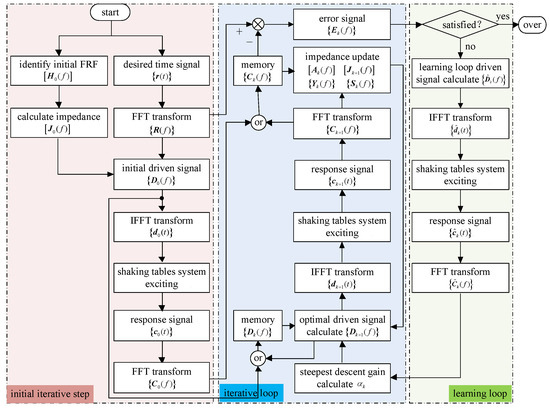
Figure 4.
Adaptive iteration learning control process diagram for shaking tables.
From Figure 4, it can be seen that the control process contains three main parts: an initial iterative step, iterative loop and learning loop. In this process, the iterative loop and learning loop are performed alternately until the control precision at each frequency is satisfactory. After the control precision is satisfied at a particular frequency, then the driven spectrum at this frequency does not change at all and the iteration repeat is only still performed at other frequency points. The repeat control can realize the fast and stable adaptive optimization iteration control of the shaking tables system and accurately reproduce the acceleration time domain waveform.
5. Experiment Results and Analysis
The experiment system was built to test the researched content above. The total control system is shown in Figure 5, and mainly contains a hydraulic power manager unit, manager PC, motion controller, emergency button, target PC, signal condition unit, PLC, hydraulic power, shaking tables and test specimen. The main parameters of the experiment system are listed in Table 1. The real-time control experiment system is based on the xPC rapid prototype control technology, in which the system sample time is 0.001 s. The hydraulic power is controlled by PLC, which is communicated with through the RS485. The host manager PC is communicated with through the network. The real-time control system is built applying Matlab/Simulink, which is compiled to the real-time control program and then down to the target PC. The target PC adopts the industrial computer of the National Instrument, and the host PC is a common computer with the Windows 7 system. The condition unit mainly translates the acquired acceleration signal, displacement signal and the servo valve driving signal into the appropriate types. The motion controller mainly contains the signal acquisition A/D card, signal driving card D/A and number I/O card, which are communicated with through the signal condition unit. The experiment setup is as follows:
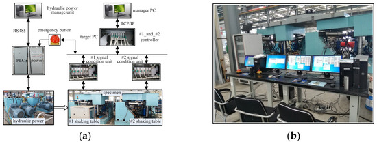
Figure 5.
Shaking tables experiment system. (a) Real-time control system, (b) Built experiment systems.

Table 1.
Main parameters of the shaking tables system.
5.1. Tests Using Exactly Identified FRF Model
To make comparisons, two series of experimental tests were performed through adopting two kinds of identified system FRF models: small and large estimation errors. Each series of tests compares the control effects of the traditional offline iterative control method usually used in shaking table control in practice and the proposed adaptive iterative learning control method. The iteration control algorithm of the shaking tables system is realized in the frequency domain, whose control essence is the reduction in control error in the frequency domain at each frequency. The signal described in the frequency domain is a complex that contains two factors: a real part and imaginary part. Thus, some signals and control parameters during the control process will be described in complex vector form in this section. The experiment results and detailed comparison analysis are shown in the following part of the paper.
It should be noted that shaking tables are mainly used to simulate earthquake vibration environments, whose motion waveforms are usually three translations along the X, Y and Z axes. Therefore, the tests and analysis are also implemented in three translation directions in this paper. Due to the shaking tables test being mainly an earthquake waveform test, which performs the characteristic of randomness, this section presents tests for various cases using an earthquake waveform random signal, whose amplitude is about ±0.4 g, frequency range is 0.1~20 Hz, duration time is 20 s and control channel is six, corresponding to directions X1, Y1, Z1, X2, Y2, Z2 of the shaking tables, as shown in Figure 6.
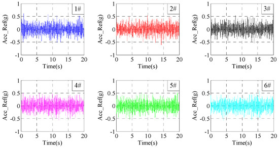
Figure 6.
Time–waveform curves of six reference signals.
This section presents the tests using the traditional iteration learning control and proposed adaptive iteration learning control method with relatively accurate FRF estimation, respectively. The amplitude and phase of the real and estimated FRFs are, respectively, shown in Figure 7 and Figure 8, in which blue curves are the real FRF model and red curves are the estimated FRF model. It can be seen that the errors between the real FRF model and estimated FRF model are relatively small, especially in the frequency range 0.1~20 Hz, which is the main frequency of the reference signal.
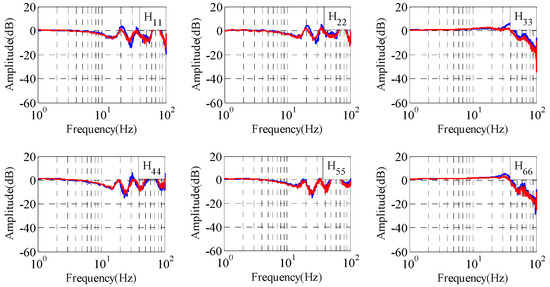
Figure 7.
Amplitude frequency characteristics of shaking tables.
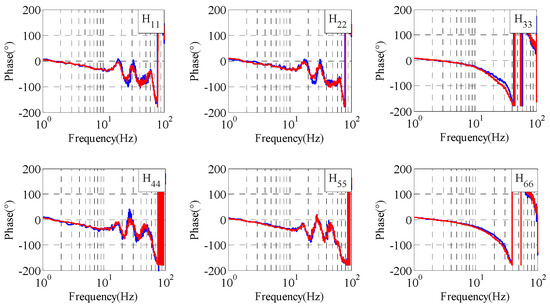
Figure 8.
Phase frequency characteristics of shaking tables.
5.1.1. Experiments Using Traditional Iteration Learning Control Method
This section will present experiments using traditional iteration control with different iteration gains. The system control errors at the 300th frequency point (which is 14.947 Hz) with iteration gain 0.2 are shown in Figure 9. The time domain control errors after 20 iterations are shown in Figure 10. The system RMSEs (root mean square errors) with the increase in iteration time are shown in Figure 11.
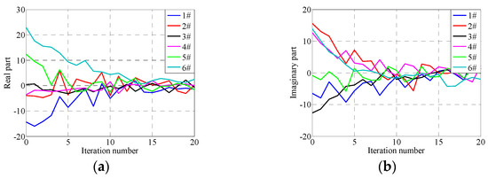
Figure 9.
Errors in 300th frequency under traditional iterative control with gain 0.2. (a) Real part, (b) Imaginary part.
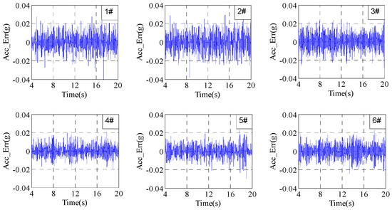
Figure 10.
Errors under traditional iterative control with gain 0.2 after 20 iterations.
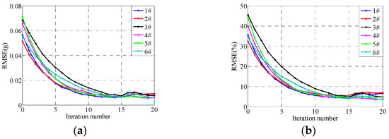
Figure 11.
RMSEs under traditional iterative control with gain 0.2. (a) Absolute RMSEs, (b) Relative RMSEs.
The absolute RMSE and the relative RMSE are, respectively, defined as follows:
where is the reference signal sequence, is the response signal sequence and and , respectively, describe the root mean square and mean value of .
From Figure 9, Figure 10 and Figure 11, it can be seen that the convergence rates are slow when the iteration gain is 0.2; the system RMSEs are about 10% after 10 iterations and are about 0.01 g after 20 iterations, which is about 5% relative to the reference signal RMSs about 0.2 g. Furthermore, it can be seen from Figure 11 that the difference in control errors between different channels in each iteration step are large. Note that the control errors after the 15th iteration do not decrease at all, which is because the system inevitably includes various factors such as electrical noise, pressure fluctuation of the hydraulic power supply and so on.
The control errors at the 300th frequency point with iteration gain 0.7 are shown in Figure 12. The time domain control errors after 20 iterations are shown in Figure 13. The RMSEs with the increase in iteration time are shown in Figure 14. From Figure 12, Figure 13 and Figure 14, it can be seen that the convergence rates become fast when the iteration gain is 0.7; the system RMSEs are about 0.01 g after five iterations, which are about 5% relative to the reference signals. The system control errors converge to the minimized control errors after five iterations and the errors will not decrease at all with the increase in iteration time.
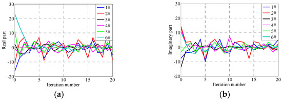
Figure 12.
Errors in 300th frequency under traditional iterative control with gain 0.7, (a) Absolute RMSEs, (b) Relative RMSEs.
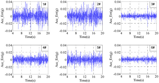
Figure 13.
Errors under traditional iterative control with gain 0.7 after 20 iterations.
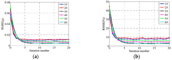
Figure 14.
RMSEs under traditional iterative control with gain 0.7, (a) Absolute RMSEs, (b) Relative RMSEs.
5.1.2. Experiments Using Adaptive Iteration Learning Control Method
This section will present tests applying the proposed adaptive optimization iteration learning control. The learning loop iteration gains are set to the same value, 0.2, in six directions, and the threshold value of control error during the iteration process is set to 10−5, that is, when the ratio of the control error and reference signal is less than 10−5, the system impedance and the complex steepest descent gain stop updating. The control errors, complex steepest descent gain and the main diagonal elements of the system impedance matrix at the 300th frequency point with the increase in iteration time are, respectively, shown in Figure 15, Figure 16 and Figure 17. The time domain control errors after 20 iterations are shown in Figure 18 and the system RMSEs with the increase in iteration time are shown in Figure 19.
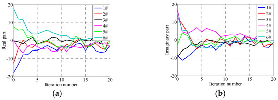
Figure 15.
Errors in 300th frequency under adaptive iterative control. (a) Real part, (b) Imaginary part.
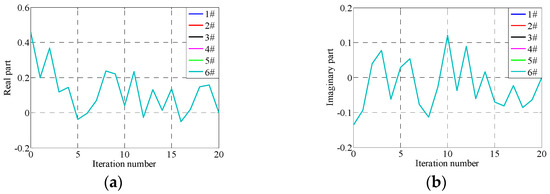
Figure 16.
Optimal adaptive gain in 300th frequency under adaptive iterative control. (a) Real part, (b) Imaginary part.
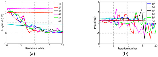
Figure 17.
Impedance matrix update in 300th frequency under adaptive iterative control. (a) Amplitude of impedance matrix, (b) Phase of impedance matrix.
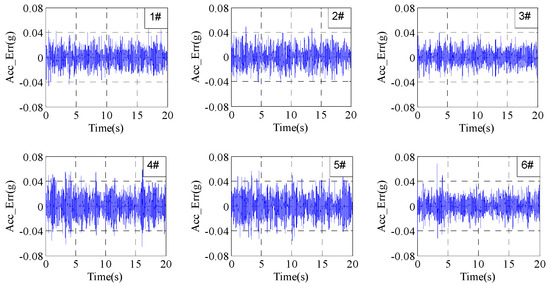
Figure 18.
Errors after 20 iterations under adaptive iterative control.
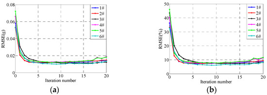
Figure 19.
RMSEs under under adaptive iterative control, (a) Absolute RMSEs, (b) Relative RMSEs.
From Figure 15, Figure 16, Figure 17, Figure 18 and Figure 19, it can be seen that the control errors converge to about 0.01 g after only three iterations applying the proposed adaptive optimization iteration learning control method. Compared with traditional iteration control, with an iteration gain of 0.7, the proposed control method has a faster convergence rate, which is because it adopts different optimal iteration gains at each frequency point. Furthermore, from Figure 11, Figure 14 and Figure 19, it can be seen that the differences between each channel’s RMSEs are relatively small compared with traditional iteration control. This is because the former treats all channels of shaking tables as an entirety, and the iteration gain is calculated based on the entire system optimization algorithm. However, the traditional iteration control method applies the same not-optimized iteration gain and the gain makes one channel converge easily and the others converge poorly. Furthermore, with the convergence of control errors, the real part of the optimized iteration gain tends to one and the imaginary part tends to zero. The system impedance matrix does not converge to the real value, but the actual value will tend to the real value with the increase in iteration time, which is because the purpose of the proposed adaptive iterative learning control method is to minimize the system control error and not to obtain a precise system impedance value. The experiment results indicate that the proposed adaptive optimization iteration learning control method based on the proposed complex optimization algorithm and complex steepest descent algorithm has a faster convergence rate compared with the traditional iteration control method.
5.2. Tests Using Large Error-Identified FRF Model
This section presents tests using the traditional iteration learning control method and proposed adaptive optimization iteration learning control method, respectively, when the system FRF model estimation error is relatively large. The amplitude and phase of the real and estimated FRFs are, respectively, shown in Figure 20 and Figure 21, in which blue curves are the real FRF model and red curves are the estimated FRF model. It can be seen that the errors between the real FRF model and estimated FRF model are large in the frequency range 0.1~20 Hz, which is the main frequency of the reference signal. In particular, the maximum of the phase error is about 180°, so it is very easy to make the control system unstable, as mentioned above.
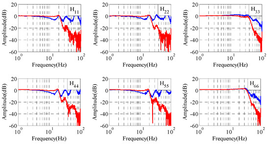
Figure 20.
Amplitude frequency characteristics of shaking tables.
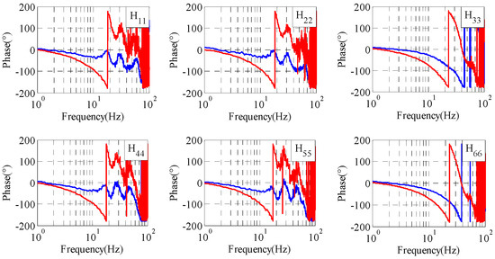
Figure 21.
Phase frequency characteristics of shaking tables.
5.2.1. Experiments Using Traditional Iteration Learning Control Method
Corresponding to Section 5.1.1, this section will also present tests using the traditional iteration learning control method. The system control errors at the 300th frequency point with iteration gain 0.1 are shown in Figure 22. The system time domain control errors after 20 iterations are shown in Figure 23. The system RMSEs with the increase in iteration time are shown in Figure 24. Note that the iteration gain 0.1 (not 0.2 or 0.7 in this part) is chosen to ensure that the test system is relatively stable and controllable and is not destroyed.
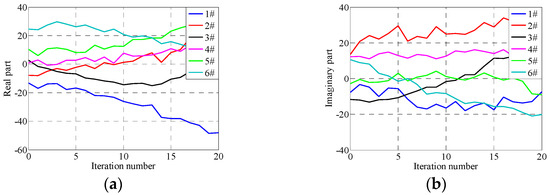
Figure 22.
Errors in 300th frequency under traditional iterative control with gain 0.1. (a) Real part, (b) Imaginary part.
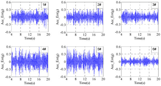
Figure 23.
Errors under traditional iterative control with gain 0.1 after 20 iterations.
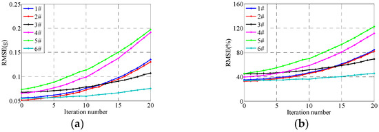
Figure 24.
RMSEs under traditional iterative control with gain 0.1. (a) absolute RMSEs, (b) relative RMSEs.
From Figure 22, Figure 23 and Figure 24, it can be seen that the control system is not convergent even if using the relatively small iteration gain of 0.1, which is because the error between the actual and estimated system FRF is relatively large, and the phase error is larger than 180° at some frequency points. In this case, the applied iteration gain and the system FRF estimation error cannot satisfy the stable condition of the iteration control shown in Equation (13). The compensation control in this case is equivalent to a reversed compensation, that is, this compensation control makes the control errors increase along with the increase in the iteration time. The experiment results indicate the validity of the traditional iteration control stability analysis.
5.2.2. Experiments Using Adaptive Iteration Learning Control Method
Corresponding to Section 5.1.2, this section presents tests applying the proposed adaptive optimization iteration learning control method. The learning loop iteration gains are set to the same value, 0.2, in six directions and the threshold value of the control error during iteration process is set to 10−5. The control errors at the 300th frequency point with the increase in iteration time are shown in Figure 25, the complex steepest descent gain at the 300th frequency point is shown in Figure 26 and the main diagonal elements of the system impedance matrix at the 300th frequency point are shown in Figure 27. The time domain control errors after 20 iterations are shown in Figure 28 and the system RMSEs with the increase in iteration time are shown in Figure 29.
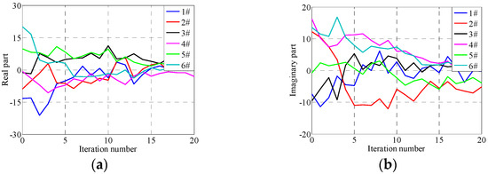
Figure 25.
Errors in 300th frequency under adaptive iterative control. (a) Real part, (b) Imaginary part.
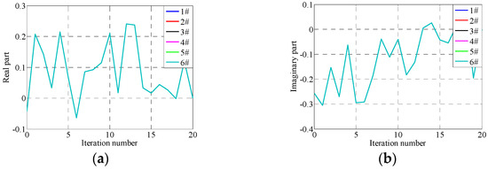
Figure 26.
Optimal adaptive gain in 300th frequency under adaptive iterative control. (a) Real part, (b) Imaginary part.
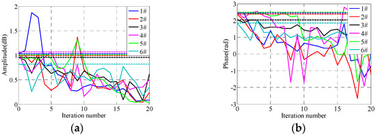
Figure 27.
Impedance matrix update in 300th frequency under adaptive iterative control. (a) Amplitude of impedance matrix, (b) Phase of impedance matrix.
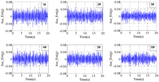
Figure 28.
Errors after 20 iterations under adaptive iterative control.
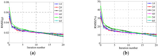
Figure 29.
RMSEs under adaptive iterative control. (a) Absolute RMSEs, (b) Relative RMSEs.
From Figure 25, Figure 26, Figure 27, Figure 28 and Figure 29, it can be seen that the system RMSEs converge to about 0.023 g, which is about 15% relative to the reference signal, after five iterations using the proposed adaptive optimization iteration learning control method. The system RMSEs converge to about 0.02 g after 15 iterations, which is about 10%, and the control errors converge with the increase in iteration time. Compared with the results applying the traditional iteration learning control method shown in Figure 22, Figure 23 and Figure 24, the proposed control method has successfully solved the potentially unstable problem of the traditional iteration learning control method when the system FRF estimation error is relatively large in some frequency points. Furthermore, with the convergence of control errors, the real part of the optimized iteration gain tends to one and the imaginary part tends to zero during the iteration process. The system impedance matrix does not converge to the real value, but the actual value will tend to the real value with the increase in iteration time, which is similar to the results in Section 5.1.2.
Combining the experiment results in this and the above sections, it can be seen that the proposed adaptive optimization iteration learning control method based on the complex optimization algorithm and complex steepest descent algorithm makes the control system convergent no matter if the system FRF model estimation error is small or large. The proposed control method has a stronger robustness to system FRF model estimation error, and it has a faster convergence rate when applying the same system FRF estimation model compared with the traditional iteration learning control method, which indicates that the proposed adaptive optimization iteration learning control method is effective and feasible, and can accurately realize the acceleration time domain waveform replication of shaking tables systems.
6. Conclusions
In this paper, the adaptive iterative learning control method based on the complex optimization algorithm was proposed to overcome the problem of the traditional iteration learning control method. The complex Broyden optimization algorithm combined with complex steepest descent gain is deduced according to the real Broyden optimization algorithm and the mapping relationship between real vector space and complex vector space. The shaking tables experiment system is built based on xPC target rapid prototyping technology. The tests performed use the proposed adaptive iterative learning control and traditional iterative learning control, respectively, under two conditions: with relatively accurate system FRF estimation and with a large system FRF estimation error. The percent RMSE of the reference signal (RMS is about 0.2 g) can decrease to 5% (about 0.01 g) within three iterations using the proposed control method and at least 20 iterations using the traditional method with iterative gain 0.2, and can only decrease to a minimum of 10% within 10 iterations with iterative gain 0.7 when the estimated FRF error is relatively small. When the estimated FRF error is large, the system is not stable and convergent using the traditional method, even with an iteration gain of 0.1, and the RMSE can still decrease to 15% (0.023 g) within five iterations and the control error will keep decreasing with the increase in iteration time. The experiment results indicate that the proposed control method makes the control system convergent no matter if the system FRF estimation error is small or large, and it has a faster convergence rate and stronger robust stability.
Author Contributions
L.Z. contributed to analyzing and interpreting the data for this research; J.F. and R.H. contributed to the research idea; P.H. and X.L. contributed to analyzing and interpreting the data for this research. All authors have read and agreed to the published version of the manuscript.
Funding
This research was funded by the National Natural Science Foundation of China (52205064, 62003227), the S&T Program of Hebei (E2021210065, E2020210080, E2021210116, E2019210104) and the Funded by Science and Technology Project of Hebei Education Department (QN2019224, QN2023035).
Data Availability Statement
Not applicable.
Conflicts of Interest
The authors declare no conflict of interest.
References
- Yeow, T.Z.; Kusunoki, K.; Nakamura, I.; Hibino, Y.; Fukai, S.; Safi, W.A. E-defense shake-table test of a building designed for post-disaster functionality. J. Earthq. Eng. 2022, 26, 5153–5174. [Google Scholar] [CrossRef]
- Kallioras, S.; Correia, A.A.; Graziotti, F.; Penna, A.; Magenes, G. Collapse shake-table testing of a clay-URM building with chimneys. Bull. Earthq. Eng. 2019, 18, 1009–1048. [Google Scholar] [CrossRef]
- Shimada, Y.; Takahashi, K.; Yamada, S. Collapse Behavior of Reduced-Scale Frames by the Inverted Shaking Table Method under Dynamic Seismic Loading. Int. J. Steel Struct. 2022, 22, 1798–1807. [Google Scholar] [CrossRef]
- Lin, Y.; Chen, Y.; Zong, Z.; Lin, J.; Tang, G.; He, X. A New Hybrid Input Strategy to Reproduce Across-Fault Ground Motions on Multi-Shaking Tables. J. Test. Eval. 2020, 49, 691–712. [Google Scholar] [CrossRef]
- Gu, Q.; Yuan, B.; Ozcelik, O.; Chang, R.; Guo, W.; Zhou, H.; Lin, J.-Y.; Wang, T.; Zhang, J. A Novel Moving Load Integration Method for Real-Time Hybrid Shaking Table Test of High-Speed Maglev Vehicle–Bridge Interaction System. Int. J. Struct. Stab. Dyn. 2022, 22, 2241013. [Google Scholar] [CrossRef]
- Han, J.; Guo, Z.; Zhong, Z.; El Naggar, M.H.; Miao, H.; Du, X. Free-field soil response to bidirectional horizontal non-uniform ground motion from multi-point shaking table tests. Soil Dyn. Earthq. Eng. 2022, 163, 107512. [Google Scholar] [CrossRef]
- Guo, W.; Feng, B.; Yu, M.; Jie, Z. Design of multi-array shaking table tests under uniform and non-uniform earthquake excitations. Soil Dyn. Earthq. Eng. 2022, 153, 107114. [Google Scholar]
- Yao, J.; Li, Y.; Yu, X.; Liu, Y.; Sun, S.; Yan, Y. Acceleration harmonic identification for an electro-hydraulic shaking table based on the Simulated Annealing-Particle Swarm Optimization algorithm. J. Vib. Control 2022. [Google Scholar] [CrossRef]
- Dai, K.; Zhu, Z.; Shen, G.; Tang, Y.; Li, X.; Wang, W.; Wang, Q. Adaptive force tracking control of electrohydraulic systems with low load using the modified LuGre friction model. Control Eng. Pract. 2022, 125, 105213. [Google Scholar] [CrossRef]
- Di Filippo, G.; Casablanca, O.; Biondi, G.; Cascone, E. Calibration of a large shaking table equipment for testing geotechnical physical models under plane strain conditions. Soil Dyn. Earth Eng. 2023, 166, 107726. [Google Scholar] [CrossRef]
- Guo, W.; He, C.; Shao, P. A novel system identification method for servo-hydraulic shaking table using physics-guided long short-term memory network. Mech. Syst. Signal Pract. 2022, 178, 109277. [Google Scholar] [CrossRef]
- Huang, Q.; Wang, P.; Wang, Y.; Yang, Q. Decoupling Control of a Multiaxis Hydraulic Servo Shaking Table Based on Dynamic Model. Shock. Vib. 2021, 2021, 1–12. [Google Scholar] [CrossRef]
- Li, F.; Li, X.; Wang, J. Effects of Interaction between Dual Shaking Tables and Specimen and Force Feedback Compensation Control. Shock. Vib. 2018, 2018, 1–12. [Google Scholar] [CrossRef]
- Soleymani, M.; Khalatabari-S, A.; Ghanbari-S, B. Fuzzy-Sliding-Mode Supervisory Control of a Seismic Shake Table with Var-iable Payload for Robust and Precise Acceleration Tracking. J. Earth Eng. 2017, 2017, 1–18. [Google Scholar]
- Zhao, J.; Sun, X.; Xu, J.; Dong, J.; Li, W.; Zhang, C. Modal space three-state feedback and feedforward control for 2-DOF elec-tro-hydraulic servo shaking table with dynamic coupling caused by eccentric load. Mechatronics 2021, 79, 102661. [Google Scholar] [CrossRef]
- Cheng, Y.; Li, B.; Wang, J.; Li, H. Research on PSD Replication for Multiaxial Hydraulic Vibration Test System Based on FXLMS Algorithms. Shock. Vib. 2021, 2021, 6610817. [Google Scholar] [CrossRef]
- Cryer, B.W.; Nawrocki, P.E.; Lund, R.A. Road simulation system for heavy duty vehicles. In Proceedings of the Automotive Engineering Congress and Exposition, Detroit, MI, USA, 23–27 February 1976; pp. 1–13. [Google Scholar]
- MTS. RPC III Simulation Testing Analysis and Control System. Software Handbook. MTS Systems Corporation Brochure RPC III-01, (Part no. 300137-01). 1996. Available online: https://www.mts.com/en/products/software-monitoring/rpc-connect-software#technical (accessed on 10 February 2023).
- Plummer, A.R. Control techniques for structural testing: A review. Proc. Inst. Mech. Eng. Part I J. Syst. Control Eng. 2007, 221, 139–169. [Google Scholar] [CrossRef]
- Underwood, M.A.; Ayres, R.; Keller, T. Some aspects of using measured data as the basis of a multi-exciter vibration test. Struct. Dynam. 2011, 3, 939–954. [Google Scholar]
- Bladh, K. Virtual Full Vehicle Durability Testing of a Coach. Master’s Thesis, Sweden Kungliga Tekniska Högskolan, Stockholm, Sweden, 2012. [Google Scholar]
- Eksteen, J.J.A. Advances in Iterative Learning Control with Application to Structural Dynamic Response Reconstruction. Ph.D. Thesis, University of Pretoria, Pretoria, South Africa, 2014. [Google Scholar]
- Yang, Z.D.; Zhang, Y.Y.; Cong, D.; Yu, Y. Iterative approach of tire-coupled road simulator based on singularity threshold criterion. In Proceedings of the International Conference on Fluid Power and Mechatronics, Harbin, China, 5–7 August 2015; pp. 444–447. [Google Scholar]
- Liu, X.Y.; Yang, Q.Y.; Shi, R. Adaptive inverse control of shock vibration based on filter-X least mean square algorithm. J. Xi’an Jiaotong Univ. 2004, 38, 144–148. [Google Scholar]
- Cornelis, B.; Toso, A.; Verpoest, W.; Peeters, B. Improved MIMO FRF estimation and model updating for robust time waveform replication on durability test rigs. In Proceedings of the International Conference on Noise and Vibration Engineering, Leuven, Belgium, 15–17 September 2014; pp. 737–752. [Google Scholar]
- Moten, S.; Pipeleers, G.; Desmet, W.; Swevers, J. A combined use of the adaptive inverse plant modeling and iterative learning control strategy for service load simulations. Control Conf. 2015, 73, 277–282. [Google Scholar]
- Cuyper, D. Linear Feedback Control for Durability Test Rigs in the Automotive Industry; Katholieke Universiteit Leuven: Leuven, Belgium, 2006. [Google Scholar]
- Tang, Y.; Shen, G.; Zhu, Z.C.; Li, X.; Yang, C.F. Time waveform replication for electro-hydraulic shaking table incorporating off-line iterative learning control and modified internal model control. Proc. Inst. Mech. Eng. Part I J. Syst. Control Eng. 2014, 228, 722–733. [Google Scholar] [CrossRef]
- Smolders, K.; Volckaert, M.; Swevers, J. Tracking control of nonlinear lumped mechanical continuous-time systems: A model-based iterative learning approach. Mech. Syst. Signal Process. 2014, 22, 1896–1916. [Google Scholar] [CrossRef]
- Daley, S.; Owens, D.H.; Hätönen, J. Application of optimal iterative learning control to the dynamic testing of mechanical structures. Proc. Inst. Mech. Eng. Part I J. Syst. Control Eng. 2007, 221, 211–222. [Google Scholar] [CrossRef]
- Underwood, M.A. Adaptive Control Method for Multiexciter Sine Tests. U.S. Patent 5,299,459, 19 April 1994. [Google Scholar]
- Yang, D.Z.; Cong, D.C.; Han, J.W.; Li, H.R. Single-axis swept sine vibration control using extended Quasi-Newton method. J. Vib. Shock 2008, 3, 99–103. [Google Scholar]
- Roberts, D.E.; Hay, N.C. Dynamic response simulation for a nonlinear system. J. Sound Vib. 2005, 281, 783–798. [Google Scholar] [CrossRef]
- Gunnarsson, S.; Norrlöf, M. On the design of ILC algorithms using optimization. Automatica 2009, 37, 2011–2016. [Google Scholar] [CrossRef]
- Li, H.; Adali, T. Complex-valued adaptive signal processing using nonlinear functions. EURASIP J. Adv. Signal Process. 2007, 1, 1–9. [Google Scholar] [CrossRef]
- Brandwood, D.H. A complex gradient operator and its application in adaptive array theory. IEE Proc. F Com-Munications Radar Signal Process. 1983, 130, 11–16. [Google Scholar] [CrossRef]
- Hjrungnes, A. Complex Valued Matrix Derivatives with Applications in Signal Processing and Communications; Cambridge University Press: Cambridge, UK, 2011. [Google Scholar]
- Kreutzdelgado, K. The complex gradient operator and the CR-calculus. Mathematics 2009, 1–74. [Google Scholar] [CrossRef]
- Sorber, L.; Barel, M.V.; Lathauwer, L.D. Unconstrained optimization of real functions in complex variables. SIAM J. Optim. 2012, 22, 879–898. [Google Scholar] [CrossRef]
Disclaimer/Publisher’s Note: The statements, opinions and data contained in all publications are solely those of the individual author(s) and contributor(s) and not of MDPI and/or the editor(s). MDPI and/or the editor(s) disclaim responsibility for any injury to people or property resulting from any ideas, methods, instructions or products referred to in the content. |
© 2023 by the authors. Licensee MDPI, Basel, Switzerland. This article is an open access article distributed under the terms and conditions of the Creative Commons Attribution (CC BY) license (https://creativecommons.org/licenses/by/4.0/).