Abstract
With the increasing exploitation and use of marine resources, the limitations of acoustic, optical, and radio frequency technologies for underwater communications have become increasingly apparent. Magnetic induction (MI) is a new communication technology that enables wireless data transmission via magnetic field coupling between transmitting and receiving coils. MI offers advantages such as channel stability, small antenna size, and no multi-path loss. Multi-input–multi-output (MIMO) is a multi-antenna technology that significantly increases system capacity and spectrum utilization without increasing bandwidth. The whale optimization algorithm (WOA) is a well-known bio-inspired algorithm that mimics the hunting behavior of whales to optimize swarm intelligence. This paper proposes a model for an underwater MIMO communication system based on magnetic induction. We then construct a signal detection algorithm for MI-MIMO systems using the advanced whale optimization algorithm (AWOA) and conduct simulation experiments to compare the performance and complexity of three standard signal detection algorithms: zero-forcing (ZF), minimum mean square error (MMSE), and maximum likelihood (ML). The experimental results show that AWOA achieves suboptimal results, as its bit error rate (BER) is close to that of the ML algorithm. Furthermore, the complexity of AWOA is comparable to that of the MMSE strategy. This work supports the development of a high-performance MI-based underwater communication system.
1. Introduction
The underwater sensor network consists of nodes equipped with wireless communication and information processing capabilities, which profoundly impact marine data acquisition and environmental monitoring [1]. Traditional underwater communication technologies include acoustic, electromagnetic, and optical technologies. However, acoustic technology has limitations such as multi-path effects, time-varying effects, low capacity, and other drawbacks [2]. Although underwater electromagnetic communication technology offers advantages such as high communication rates and high noise immunity, the high electrical conductivity of seawater causes severe signal attenuation and multi-path effects, which limit its application [3]. In contrast, underwater optical communication uses lasers as information carriers with ultra-high transmission bandwidth, high transmission rates, and low time delay. However, water bodies’ significant absorption and scattering effects on optical communication can seriously affect the quality of communication [4].
Magnetic induction (MI) is a wireless communication method that uses the transmitting antenna coil to generate a magnetic field and the receiving coil to generate an induced current. MI uses magnetic fields for communication, which has several advantages, including low power consumption, low latency, stable channels, multi-path effects [5], and the absence of Doppler effects. Research has shown that the magnetic permeability of MI is almost identical in soil, water, and air and that MI has practically no impact on communication when passing through the water–air interface [6]. The communication distance is approximately the same in all three environments, with slight variations in the channel [7]. Numerous applications for MI in underwater communications have been identified [8,9]. Multi-input–multi-output (MIMO) can significantly increase transmission rates and spectral efficiency with limited bandwidth by increasing the number of antennas at the transmitting and receiving ends [10,11]. However, signal detection in MIMO systems is challenging due to the mutual interference between different transmit antennas and the multi-path effects of the communication systems. Traditional signal detection algorithms such as the zero-forcing (ZF) algorithm [12], minimum mean square error (MMSE) [13], and maximum likelihood (ML) [14] fail to achieve a trade-off between performance and complexity in energy- and power-constrained underwater networks. The whale optimization algorithm (WOA) is a bionic method [15] that mimics the hunting behavior of humpback whales. WOA has been applied to wireless resource allocation [16,17], wireless network energy clustering [18], cloud computing [19], and other areas. This paper presents a model of an underwater MI-MIMO communication system and develops an advanced whale optimization algorithm (AWOA) for signal detection. We attempt to optimize the signal detection of the MI-MIMO system based on AWOA. The main contributions of this paper are as follows:
- (1)
- We propose a model of an underwater MIMO communication system based on magnetic induction technology;
- (2)
- We implement AWOA, an advanced whale optimization algorithm, to achieve signal detection in the proposed underwater MI-MIMO system;
- (3)
- We perform simulation experiments to compare the performance and complexity of AWOA with three standard signal detection algorithms, namely ZF, MMSE, and ML.
2. Related Work
2.1. Underwater Magnetic Induction MIMO Communication
The study of underwater magnetic induction communication has attracted considerable attention from academia and industry worldwide. Li Z. et al. [20] extended the range of underwater communication using a spherical magnetic induction antenna. Zhang Y. et al. [21] constructed an MI-based multi-hop network to study the distance of underwater MI communication while ensuring the bit error ratio (BER) by extending the communication range through relay nodes. Guo H. et al. [22] used MIMO in magnetic induction communication to analyze the signal transmission loss and channel capacity of the 2 × 2 and N × N antenna array and designed MI-MIMO antennas using metamaterials. In addition, Guo H. et al. [23] used three-way coils for MI-MIMO communication and achieved low power consumption and high information throughput for underwater autonomous robots by selecting appropriate coils. To build an underwater communication system, Tal N. et al. [24] reduced antenna crosstalk by partially overlapping antenna coils in a 3 × 3 or 4 × 4 MI-MIMO system. Kim H. J. d. et al. [25] designed a heterogeneous antenna array that enabled MI-MIMO channel capacity to eliminate inter-coil crosstalk, providing a new antenna combination for underwater MI-MIMO communication. Nguyen H. et al. [26] introduced magnetically induced MIMO system models and revealed that using more receivers for better downlink communication is desirable to increase communication capacity.
In addition, Nguyen H. et al. [27] constructed an MI-MIMO system on an FPGA board using different frequencies and transmission rates. In contrast, Zhou W. et al. [28] used orthogonal frequency division multiplexing (OFDM) technology for underwater magnetic induction communication to increase signal capacity and improve signal immunity. Hoa D. T. [29] integrated OFDM with MI-MIMO to thoroughly analyze dual-coil, tri-coil, quad-coil, and N × N-array magnetic induction systems. Wang J. et al. [30] built an OFDM-based magnetic induction communication model to create a multi-input–single-output (MISO) system that fully utilizes each frequency to achieve high-speed data transmission. In this model, multiple transmit antennas are configured at the transmitter side and a single antenna at the receiver side. Li Z. et al. [31] designed a heterogeneous MIMO communication network for acoustic and magnetic induction communication to achieve high-speed data transmission in water. Li S. et al. [32] investigated the influence of MI communication on the channel capacity after using MIMO technology. They derived the capacity and loss formula of the MI-MIMO system without signal crosstalk. Kisseleff S. et al. [33] discussed the transmit-side channel estimation without receiver channel information feedback when using MI communication. Ren Q. et al. [34] presented an underwater magnetic induction (MI)-assisted acoustic cooperative MIMO system. They proposed an optimization algorithm based on cooperative MIMO, for which the expected transmission distance and power constraints were considered. Ren Q. et al. [35] proposed a mathematical model to analyze the connectivity of the underwater MI-assisted acoustic cooperative MIMO systems. The lower and upper bounds of the connectivity probability were derived, providing guidelines for the network design and deployment.
2.2. Underwater MIMO Signal Detection
MI-based MIMO technology is a standard method for improving channel capacity, but it can lead to challenges in signal demodulation. Therefore, designing a signal detection algorithm for the MI-MIMO system is critical. The zero-forcing (ZF) method is typically used to eliminate interference in underwater channels, but it amplifies noise during the solution process, leading to signal recovery problems. In contrast, the minimum mean square error (MMSE) approach solves the noise amplification problem but with higher complexity than ZF. The maximum likelihood (ML) method has the highest decoding success rate but involves a significant amount of computation, limiting its practical application. Therefore, developing an MI-MIMO detection algorithm with low complexity and a low bit error rate is necessary. Hwang S. H. [36] investigated signal detection for MI-MIMO systems with misalignment coils, no signal crosstalk, and available channel state information and found that using a singular value decomposition (SVD) could provide superior detection results. Zhao G. et al. [37] applied the enhanced MMSE approach to the underwater acoustic MIMO-OFDM system, which resulted in suboptimal signal identification accuracy and complexity. Jiang F. et al. [38] decomposed a large matrix into smaller ones to enable fast detection in underwater MIMO systems. Wang J. et al. [39] used a deep learning network for signal detection in an underwater acoustic system, which gave better detection results than the maximum ratio combining (MRC) but lower than ML. Qin X. et al. [40] used the sparse Bayesian function for iterative signal detection in an underwater acoustic MIMO system, achieving good BER performance with limited iterations. Lu H. et al. [41] used a deep network for signal detection in optical MIMO systems and found that it outperformed error minimization methods that use least squares and root-mean-square values. Ji Y.W. et al. [42] developed a generalized likelihood block detection algorithm in underwater MIMO systems, which enables fast signal detection without channel information. Yang G. et al. [43] used the MI-MIMO system for wireless power transmission, estimated the magnetic induction channel, and performed beam allocation to improve the efficiency of MI-MIMO power transmission. Marques d. S. M. et al. [44] studied low-density parity-check coded underwater acoustic communications using m-MIMO and single carrier with frequency domain equalization transmission technique. Their results show that the proposed system is an excellent model to achieve the future evolution of UWA communications, even in the presence of impulsive noise. Akhondi M. et al. [43] proposed an underwater MIMO OFDM system and employed M-ZF, a modified signal detection algorithm based on ZF, for the system. Their simulation results show that M-ZF has lower time costs and better BER.
2.3. Summary
Based on previous studies, MI communication technology has significant advantages for underwater communications, including low power consumption, low attenuation, and stable transmission across boundaries. The development of methods such as coil design, metamaterials, and repeaters has greatly promoted the development of underwater MI communication technology. Combining MIMO technology with underwater MI communication can help mitigate the effects of insufficient MI channel capacity. However, traditional signal detection algorithms for MIMO technology face the challenge of balancing complexity and BER. Acoustic and optical MIMO signal detection are two leading communication technologies that have been studied experimentally. Nevertheless, the signal detection problem of the MI MIMO system is unavoidable in the actual deployment.
Although few studies have combined the WOA with MIMO signal detection, the WOA is a promising candidate for signal detection in underwater MI-MIMO systems due to its simple implementation, fast convergence, and high computational accuracy. Improving the WOA can reduce the probability of falling into a local saddle point and increase computational accuracy. In addition, the channel characteristics of MI differ from acoustic and optical media, and power and performance are limited in underwater networks. Therefore, for underwater signal detection in MI-MIMO systems, complexity should be considered in addition to BER.
This paper aims to develop a low-complexity signal detection method for underwater MI-MIMO systems by combining the WOA with traditional MIMO signal detection. We hope this study can inspire further exploration of this promising method by relevant researchers.
3. Methodology
3.1. Underwater Magnetic Induction MIMO Communication System Model
3.1.1. The Communication Procedure of Underwater MI
Magnetic induction is a signal transmission method that utilizes a magnetic field as a carrier in aquatic environments. In this process, an electric current creates a magnetic field within a closed coil, and the receiving coil converts the magnetic field into an electric signal for communication. Figure 1 shows the process of magnetic induction communication, where TC and RC are the transmitting and receiving coils, respectively. WT and WR represent the number of turns in the transmitting and receiving coils, respectively, while At and Ar correspond to the radii of the transmitting coils. I1 denotes the current flowing through the transmitting antenna, while I2 refers to the induced current generated by the receiving antenna. The variable d represents the transmission distance, and θ is the angle of deviation between the transmitting and receiving coils.
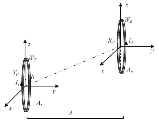
Figure 1.
Principles of magnetic induction communication.
The mutual inductance M between the coils can be expressed as (1):
where μ ≈ 4π × 10−7 H/m is the magnetic permeability. In this study, we found that the mutual inductance strength is maximum when the two coils have the exact specifications, which are shown in (2):
It is noted that these specifications apply when the two coils are aligned in parallel and coaxial with a separation distance of d.
3.1.2. The Model of Underwater MI-MIMO
Magnetic induction communication offers several advantages in underwater environments. However, its low channel capacity poses a limitation. MIMO is employed to increase channel capacity and enhance signal transmission reliability. The use of multiple receiving and transmitting antennas enables the MI-MIMO system to mitigate the effects of crosstalk signals between coils and improve the efficiency of the underwater magnetic induction channel. Figure 2 shows the schematic diagram of the MI-MIMO system with an N × N antenna array. In this figure, TX1 and TXN represent the number of transmit antennas, while TR1 and TRN refer to the number of receive antennas. CS indicates the crosstalk signal between each coil. L denotes the transmission distance, and d represents the distance between coils. The strength of the crosstalk signal between coils is directly proportional to the distance between them. The dotted line between the coils represents the transmitted signal.
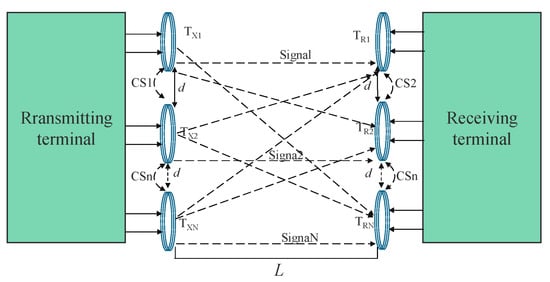
Figure 2.
N × N MI-MIMO system.
Let the channel parameter matrix be denoted by H, where the element in the matrix represents the channel response from the i-th transmitter’s antenna to the j-th receiver’s antenna. The expression for H is given by (3):
Let the vector of the transmitted signal be represented by , and the corresponding vector at the receiving end be denoted by Y. The expression for Y is given by Equation (4):
Here, represents the N*1-dimensional Gaussian white noise vector generated by the MI-MIMO system itself, where the mean value of each element is 0, and the variance is . Thus, Equation (4) can be written as (5):
The equivalent circuit schematic of the MI-MIMO system depicted in Figure 3 is derived by applying appropriate circuit transformations to the original MI-MIMO schematic.
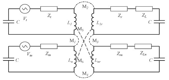
Figure 3.
N × N MIMO Schematic diagram of the equivalent circuit.
In Figure 3, the circuit elements , , , and represent the impedances of the transmitters and receivers, respectively. The load impedances of the receiver circuits are denoted by and , while C represents the capacitance of each circuit. The circuit voltage is represented by V, and Vtn means the voltage across the mutual inductance signals M1, M2, M3, M4, M5, and M6 between the coils. The interference between the coils on the same side can be eliminated by adjusting the coupling strength and coil spacing. L1, Ln, L1r, and Lnr denote the transmitting and receiving coils. When the MI-MIMO system has NT transmitting coils and NR receiving coils, the path loss can be expressed as (6) [22,32]:
The channel capacity is expressed as (7) [22,32], where represents the signal frequency. represents the mutual inductance between the T-th transmitting coil and the R-th receiving coil, is the impedance of the transmitting circuit, is the impedance of the receiving circuit, and is the load impedance of the receiving circuit.
In (7), is the identity matrix, is the signal-to-interference-plus-noise ratio, H is the channel transmission matrix, which represents the channel coefficient between antennas, and is the complex conjugate transpose of the matrix H for N receive antennas.
3.2. The Advanced Whale-Based Optimization Algorithm for Signal Detection in Underwater MI-MIMO Systems
The WOA is an optimization algorithm that emulates the hunting behavior of whales, which involves searching, circling, tracking, and attacking prey to maximize their search range. It has advantages such as faster convergence, less parameter control, and a more relaxed objective function requirement [15]. However, the traditional WOA can quickly converge to a local saddle point, which affects the optimization results. Therefore, in this paper, we propose an advanced whale optimization algorithm based on the conventional WOA. The initial population of the WOA is randomly distributed, which leads to significant uncertainty and randomness in the first generation of individuals, affecting the optimization results. We utilize the Halton sequence to optimize the initial population, evenly distributing the initial population variation to address this issue. In the traditional WOA, the parameter is essential for determining whale exploration and is calculated by , playing a linear role in the search process. In this paper, cc is redefined under different iterations to expand the search range to present a nonlinear expression. Combined with the Gaussian walk strategy, individuals can jump out of local saddle points when they fall into local optima.
The algorithm adds adaptive weight to update positions to expand the search range. The improved WOA has the same meaning as the original WOA, which is named AWOA. The steps of the AWOA are as follows:
Step 1: Set the initial values of each parameter, such as the population size G_number and the maximum iteration number MAX_z, and initialize the whale population Wi (i = 1,2…n) using the Halton sequence.
Step 2: Calculate and update the optimal selection of individual parameter values in the population, including , , , l, , and . Here, is a parameter that decreases linearly from 2 to 0 with the number of iterations, is a parameter that controls the whale’s action during prey encirclement, is a coefficient vector for the whale to swim towards the target, l is a uniformly distributed random number between 1 and −1 that plays a role in the whale’s spiral swimming, is a decision parameter that mainly determines the whale’s following action, and is a weight parameter that expands the search range. The variation patterns of , , , and are as follows:
where is the number of current iterations, is the maximum number of iterations, and represents a random number between −1 and 1.
Step 3: Use the Gaussian wandering strategy to jump out of the local optimum.
Step 4: If < 0.5 and < 1, execute the whale algorithm roundup phase.
In this context, denotes the distance vector between a specific whale’s position and the best whale position at iteration t, where t is the current iteration number. refers to the best position vector found so far in the optimization process, while and denote the position vectors of the whale at iterations t and t + 1, respectively.
If the value of p falls within the range of 0.5 to 1, the whale is in the encircling phase and approaching the prey. In this case, a random search action is executed to expand the search range.
where is a randomly selected whale from the population. When p > 0.5, the whale algorithm enters the spiral predation phase.
where represents the distance vector between the whale and the prey, and b is a constant used to define the logarithmic spiral shape, usually set to 1.
Step 5: Compute the fitness value after updating the location and population.
Step 6: Check if the maximum number of iterations is reached. If the stopping criterion is satisfied, output the best solution; otherwise, increase t by 1 and update the parameters to continue the next iteration.
For MIMO signal detection, ML detection is the best-performing algorithm within the search range of MN, where M is the modulation order, and N is the number of transmitting antennas. However, in practical applications with large modulation orders and sending antenna numbers, the computation resources required for ML detection are significant, necessitating the design of suboptimal detection algorithms.
Unlike the principle of the ML detection algorithm, the AWOA considers the transmit signal vector as the solution space. The whale randomly selects a signal vector and evaluates it using the fitness function to find the transmit signal with the smallest fitness value. This is the best detection signal for the MIMO system [44], as described in (18):
SS represents the solution space of all possible signals, is the estimated transmit signal vector, Y is the received signal, and H is the channel matrix. Therefore, Equation (18) is utilized as the fitness evaluation function in the AWOA for signal detection.
To facilitate a more comprehensive understanding of MIMO signal detection using AWOA, we designed a schematic diagram to illustrate the actions of the whales, as depicted in Figure 4.
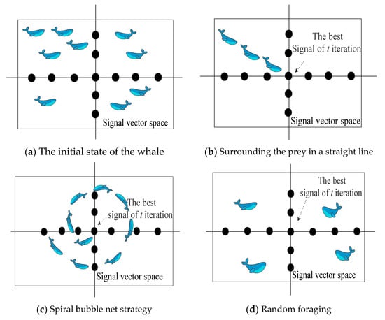
Figure 4.
The whale optimization algorithm in MI-MIMO signal detection.
As shown in Figure 4, the AWOA uses three strategies to search for the best signal vector in the solution space at iteration t. Figure 4a illustrates the whale’s initial state, where it is randomly distributed in the solution space without any target. When the control parameters p < 0.5 and < 1, the whale moves towards the best signal vector using an encircling prey strategy, as shown in Figure 4b. On the other hand, when p > 0.5, the whale adopts an ascending spiral strategy to approach the best vector, as illustrated in Figure 4c. Figure 4d demonstrates that when p < 0.5 and ≥ 1, the whale randomly searches the signal vector in the solution space. The AWOA for underwater MI-MIMO signal detection is shown as Algorithm 1:
| Algorithm 1: The AWOA for underwater MI-MIMO signal detection | |
| 1: | Input: NT, NR, Max_, and G_number |
| 2: | Output: X_aim |
| 3: | WHalton = Halton * Wi (i = 1,2…n) //Use Halton to initialize the whale population |
| 4: | //Compute the fitness of each search unit to determine the optimal value |
| 5: | //Gaussian swims out of the local saddle point |
| 6: | While (t < Max_z) |
| 7: | For i = 1 to n do |
| 8: | //Calculates and updates all parameters and adaptive weight |
| 9: | If (1) < 0.5 |
| 10: | If (2) <1 |
| 11: |
|
| 12: | Else If (2) ≥1 |
| 13: |
|
| 14: | end if (2) |
| 15: | Else If (1) ≥ 0.5 |
| 16: |
|
| 17: | //Calculate the fitness of the whale after updating the position |
| 18: | t = t + 1 |
| 19: | End while |
3.3. Performance Analysis of the WOA
In this study, we employed a population size of 100 and a maximum number of 250 iterations to determine the average minimum accuracy of the AWOA, WOA, gray wolf optimization (GWO) algorithm, and particle swarm optimization (PSO) algorithm on various benchmark test functions. These test functions included both single-peaked and multi-peaked parts, which evaluate the ability of the algorithms to solve for extreme values and jump out of local optima.
Formulas (19)–(21) are three unimodal benchmark functions that have only one optimal value. The variable denotes the range of the optimization algorithm at each position, which is [−100, 100].
Formulas (22)–(24) represent three benchmark multi-modal functions with multiple optimal values. The variable denotes the weight range of the optimization algorithm in each function.
In all benchmark functions, the optimization algorithm explores the entire range of . The algorithm calculates a value for each iteration and compares it with previous iterations to select the optimal solution. In (24), the variable c is a constant. Since the WOA has inherent advantages in finding the minimum value, the AWOA can enhance the search range of the WOA by adjusting its control parameters, resulting in improved performance in the selected test function. By comparing the results with other algorithms, the AWOA achieves the best performance, as shown in Table 1.

Table 1.
Results comparing four kinds of algorithms.
Figure 5 shows a visualization of the AWOA and its comparison with other algorithms. It shows that the AWOA reaches the optimal value after 50 iterations. In addition, AWOA achieves the smallest optimal value at the beginning of the first iteration compared with the other algorithms. Considering both the optimal value and the number of iterations, it is clear that the AWOA has a superior convergence speed and ability to find optimal solutions.
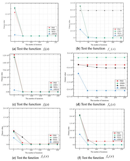
Figure 5.
Comparison of AWOA with other algorithms.
4. Experiments and Results
4.1. Experimental Parameters
We compared the AWOA with ZF, MMSE, and ML algorithms to evaluate the effectiveness of MIMO signal detection after passing through the MI channel. ZF detects the signal by inverting the received signal, while MMSE solves the signal detection problem by inverting the signal matrix and considering the effect of noise. In ML, all transmitted signals are calculated using the fitness function, and the signal with the minimum value is selected as the output signal. The AWOA performs a random selection in the signal space of the signal composition using the fitness function, and the signal with the minimum value is the output signal. To visually demonstrate the performance of the four algorithms, we created an underwater environment for experimental comparison. We compared the BER and complexity of the four algorithms without signal crosstalk. We also analyzed the performance in the same and different numbers of transmit/receive antennas. The main experimental parameters are shown in Table 2.

Table 2.
The main e×perimental parameters.
4.2. The Verification of Communication Distance
To verify the communication performance at different distances for the alignment of the transceiver coils, we set the underwater MI-MIMO communication performance in both horizontal and vertical deployment modes. The transmitter sent the address code and data code, and the receiver received and demodulated the address code and data code. The receiving coil was placed in different ways at the same distance. The number of turns of the coil was 20, and its diameter was 0.25 m. We tested the results of control signal reception and data signal reception. The relevant experimental results are shown in Table 3.

Table 3.
Decoding results in different deployment modes and distances.
The analysis of the underwater experimental data showed that when the two coils were at 3.5 m, and the receiving coil was parallel to the transmitting coil, the receiving data could be demodulated. At the same time, the vertical condition resulted in data code errors. The address and data codes failed to decode at 6.5 m between the transmit and receive coils. This shows that distance influences magnetic induction MIMO communication. The perpendicular orientation between the transceiver coils led to high data errors. Therefore, developing high-performance omnidirectional MIMO antennas will be necessary to ensure a strict magnetic field.
Experiments showed that if the transmitting and receiving antennas could not be aligned, the coupling would be lost, and the sender and receiver would not be able to maintain proper communication. We compared the end-to-end node communication distances for different frequencies, antenna radii, and maximum coil turns. The results are shown in Figure 6a. The lower the frequency, the greater the relative transmission distance. As the coil radius and the number of turns increased, the communication distance tended to increase for all three magnetic induction communication frequencies.
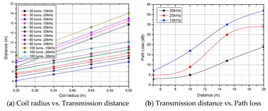
Figure 6.
Communication distance verification.
It should be noted that if the coil radius is too large and the number of turns too high, this can dramatically increase node deployment and development costs, which is unacceptable for underwater networks with many node deployments. Another point is that a too-large coil radius could make the node a specific target for submarine detection. This would defeat the purpose of magnetic induction, which is designed for secure and confidential communications. We also compared the signal path loss at different magnetic induction communication frequencies, as shown in Figure 1. The path loss increased as the communication distance increased. The lower the magnetic induction communication frequency, the higher the path loss. Magnetic induction communication with a relatively high frequency at the same distance resulted in lower communication losses.
The strength of the communication magnetic field is highly dependent on the amount of current passing through the coil, the number of turns of the coil, and the conductive magnetic material in the center. Due to power limitations of underwater nodes, underwater nodes based on disposable battery power cannot use high energy for communication, which leads to the rapid depletion of the node’s power. In addition, the use of high-performance magnetically conductive materials in the development of magnetically induced MIMO nodes also significantly impacts the communication distance of the nodes. High-performance soft magnetic materials are expensive, and some metal-based magnetically conductive materials can be subject to severe seawater corrosion and are unsuitable. The design of related active or passive relay technologies based on waveguide communication to achieve long-range underwater MI-MIMO will be an essential research task in the future. Unfortunately, these technologies are currently beyond our reach in practical scenarios. On the one hand, simulation-based techniques need to give an entirely realistic picture of underwater applications. On the other hand, deploying relayed long-range magnetically induced underwater MI-MIMO technology in deep water is still a significant challenge.
4.3. The Comparison of Bit Error Ratios
The BER is a crucial index for evaluating the performance of detection algorithms. Figure 7, Figure 8 and Figure 9 compare the BER of four algorithms under QPSK modulation with different numbers of antennas. When the number of antennas was two for both transmitters and receivers, the AWOA achieved a BER of dB. When the number of antennas increased to four, the AWOA’s BER was dB. When it was eight, the BER dropped to dB. As the average received signal-to-noise ratio increased, the BER gradually decreased. Although the increasing number of antennas leads to more interference signals, AWOA detection maintains certain advantages and exhibits noticeable BER performance, which can offer practical insights.
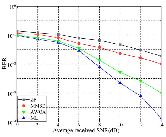
Figure 7.
BER in 2 × 2 MI-MIMO.
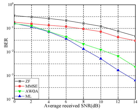
Figure 8.
BER in 4 × 4 MI-MIMO.
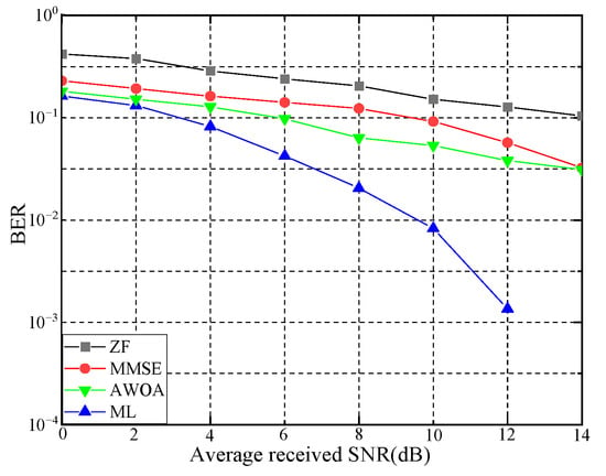
Figure 9.
BER in 8 × 8 MI-MIMO.
Figure 10, Figure 11 and Figure 12 illustrate the BER performance comparison of the four detection algorithms in the MI-MIMO system with 16-QAM modulation using different numbers of antennas. When two transmitters and four receivers were used, BER further decreased to dB. When there were four transmitters and si× receivers, the AWOA’s BER was dB. With eight receivers, the BER decreased to dB. These figures reveal that as the number of receiving antennas increased, the BER decreased following the diversity gain law. Therefore, the BER performance in MI-MIMO systems is closely related to the modulation scheme.
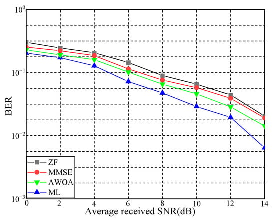
Figure 10.
BER in 2 × 4 MI-MIMO.
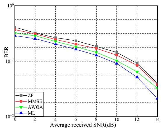
Figure 11.
BER in 4 × 6 MI-MIMO.
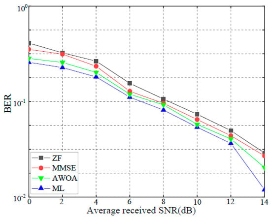
Figure 12.
BER in 4 × 8 MI-MIMO.
4.4. Complexity Comparison
The complexity of an algorithm plays a crucial role in determining the working time in underwater environments where energy replenishment is challenging. Excessive complexity leads to increased energy consumption and may result in communication failure. Among the algorithms studied in this work, the ZF algorithm has a complexity of . The MMSE algorithm is formed based on ZF but considers the noise in the system. Although the complexity of MMSE is also at the level, the presence of noise makes it slightly more complex than ZF. ML requires a traversal search in all transmitted signals, and its complexity is closely related to the number of transmitting antennas and the modulation order. The complexity of ML can be approximated as , where M is the modulation order, and N is the number of transmission antennas. The modulation order determines the complexity of the AWOA, the number of transmission antennas, the volume of transmitted data, and the number of iterations. The complexity of the AWOA is , where U is the population number, I is the maximum number of iterations, M is the modulation order, and L is the signal transmission length. It is worth noting that the complexity of the AWOA is lower than that of ML, as the number of antennas increases due to the influence of the initial population size and the number of iterations.
This paper presents the number of significant multiplication calculations for the four algorithms studied in Figure 13. It is evident that, for the same number of antennas, the complexity of the AWOA is lower than that of ML and higher than that of ZF and MMSE. Furthermore, we investigated the computation time of the AOWA for different iterations and population sizes, as shown in Figure 14. It is evident that the number of populations and iterations directly impact the complexity. Regarding complexity, ZF and MMS algorithms are the most computationally efficient. In contrast, the AWOA detection algorithm and ML algorithms use random selection and traversal concepts, leading to increased complexity.
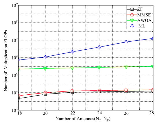
Figure 13.
The comparison of FLOPs.
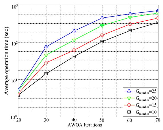
Figure 14.
Comparison of execution time.
5. Conclusions
This paper presents a novel magnetic induction-based MIMO model for underwater communications. We introduced the AWOA, an advanced whale optimization algorithm for signal detection in the MI-MIMO system, and compared its performance and complexity with conventional approaches such as ZF, MMSE, and ML. Our simulation Experiments revealed that the AWOA provided suboptimal results with a bit error rate that was similar to the ML algorithm while maintaining a complexity level comparable to the MMSE strategy. These results demonstrate the effectiveness of the AWOA in improving the performance of underwater MI-MIMO systems. Overall, the proposed model and algorithm provide potential solutions to the limitations of traditional aquatic communication systems, including issues related to attenuation, multi-path fading, and noise interference.
However, the AWOA still uses the search mechanism of the WOA, which may need to exploit the search space fully. In addition, the performance of the AWOA heavily relies on parameter selection, which is currently based on user experience and is difficult to set comprehensively and accurately in large-scale underwater MIMO systems. Our future research can introduce new search mechanisms, such as mutation and crossover, to improve the global search performance of the AWOA. We can also use a dynamic parameter tuning strategy to adjust algorithm parameters and adaptively improve algorithm performance and stability. Finally, developing an underwater MI-MIMO application system based on the improved WOA is an exciting and challenging task.
Author Contributions
Conceptualization, formal analysis, investigation, methodology, project administration, resources and validation, G.G.; data curation, funding acquisition, investigation, methodology, supervision, validation, writing—review and editing, J.W.; data curation, resources, software, supervision, validation, visualization, writing—original draft preparation, J.Z. All authors have read and agreed to the published version of the manuscript.
Funding
This work was partly supported by the Key Scientific and Technological Project of Henan Province (232102111128, 222102320181, 212102310087), the Innovation and Entrepreneurship Training Program of National College Students in China (202110467001), the Major Special Project of Xinxiang City (21ZD003), and the Key Scientific Research Projects of Colleges and Universities in Henan Province (23B520003, 21A520001). The authors approved the version of the manuscript to be published. They agreed to be accountable for all aspects of the work in ensuring that questions related to the accuracy or integrity of any part of the work are appropriately investigated and resolved.
Data Availability Statement
The data used to support this study are available from the corresponding author upon request.
Conflicts of Interest
The author declares that they have no conflict of interest.
Abbreviations
| AWOA | Advanced whale optimization algorithm |
| BER | Bit error rate |
| GWO | Gray wolf optimization |
| FLOPs | Floating point operations per second |
| MI | Magnetic induction |
| MIMO | Multi-input–multi-output |
| MMSE | Minimum mean square error |
| ML | Maximum likelihood |
| MRC | Maximal ratio combining |
| MISO | Multi-input–single-output |
| OFDM | Orthogonal frequency division multiplexing |
| PSO | Particle swarm optimization algorithm |
| QPSK | Quadrature phase shift keying |
| QAM | Quadrature amplitude modulation |
| SVG | Singular value decomposition |
| WOA | Whale optimization algorithm |
| ZF | Zero forcing |
References
- Ali, M.F.; Jayakody, D.N.K.; Chursin, Y.A.; Affes, S.; Dmitry, S. Recent Advances and Future Directions on Underwater Wireless Communications. Arch. Comput. Methods Eng 2020, 27, 1379–1412. [Google Scholar] [CrossRef]
- Editorial Underwater Acoustic Communications: Where We Stand and What Is Next? IEEE J. Ocean. Eng. 2019, 44, 1–6. [CrossRef]
- Park, D.; Chung, W.K.; Kim, J. Analysis of Electromagnetic Waves Attenuation for Underwater Localization in Structured Environments. Int. J. Control Autom. Syst. 2020, 18, 575–586. [Google Scholar] [CrossRef]
- Schirripa Spagnolo, G.; Cozzella, L.; Leccese, F. Underwater Optical Wireless Communications: Overview. Sensors 2020, 20, 2261. [Google Scholar] [CrossRef]
- Muzzammil, M.; Ahmed, N.; Qiao, G.; Ullah, I.; Wan, L. Fundamentals and Advancements of Magnetic-Field Communication for Underwater Wireless Sensor Networks. IEEE Trans. Antennas Propagat. 2020, 68, 7555–7570. [Google Scholar] [CrossRef]
- Wei, D.; Yan, L.; Huang, C.; Wang, J.; Chen, J.; Pan, M.; Fang, Y. Dynamic Magnetic Induction Wireless Communications for Autonomous-Underwater-Vehicle-Assisted Underwater IoT. IEEE Internet Things J. 2020, 7, 9834–9845. [Google Scholar] [CrossRef]
- Pierre-Jean, B.; Philippe, F.; Beatrice, T.; Yves, A.; Yassine, A.; Gilles, F.; Maelle, D.; Pauline, S. Contactless Data Transfer for Autonomous Underwater Vehicle Docking Station. In Proceedings of the OCEANS 2021, San Diego, CA, USA, 20 September 2021; pp. 1–5. [Google Scholar]
- Li, Y.; Wang, S.; Jin, C.; Zhang, Y.; Jiang, T. A Survey of Underwater Magnetic Induction Communications: Fundamental Issues, Recent Advances, and Challenges. IEEE Commun. Surv. Tutor. 2019, 21, 2466–2487. [Google Scholar] [CrossRef]
- Albreem, M.A.; Juntti, M.; Shahabuddin, S. Massive MIMO Detection Techniques: A Survey. IEEE Commun. Surv. Tutor. 2019, 21, 3109–3132. [Google Scholar] [CrossRef]
- Zhang, Y.; Cao, H.; Zhou, M.; Yang, L. Cell-Free Massive MIMO: Zero Forcing and Conjugate Beamforming Receivers. J. Commun. Netw. 2019, 21, 529–538. [Google Scholar] [CrossRef]
- Ping, L.; Paul, D.; Narasimhan, R.; Cioffi, J. On the Distribution of SINR for the MMSE MIMO Receiver and Performance Analysis. IEEE Trans. Inf.—Theory 2006, 52, 271–286. [Google Scholar] [CrossRef]
- Jain, M.; Sharma, N.; Gupta, A.; Rawal, D.; Garg, P. Performance Analysis of NOMA Assisted Underwater Visible Light Communication System. IEEE Wirel. Commun. Lett. 2020, 9, 1291–1294. [Google Scholar] [CrossRef]
- Mirjalili, S.; Lewis, A. The Whale Optimization Algorithm. Adv. Eng. Softw. 2016, 95, 51–67. [Google Scholar] [CrossRef]
- Pham, Q.-V.; Mirjalili, S.; Kumar, N.; Alazab, M.; Hwang, W.-J. Whale Optimization Algorithm with Applications to Resource Allocation in Wireless Networks. IEEE Trans. Veh. Technol. 2020, 69, 4285–4297. [Google Scholar] [CrossRef]
- Kumar, M.; Chaparala, A. OBC-WOA: Opposition-Based Chaotic Whale Optimization Algorithm for Energy Efficient Clustering in Wireless Sensor Network. IJIES 2019, 12, 249–258. [Google Scholar] [CrossRef]
- Chen, X.; Cheng, L.; Liu, C.; Liu, Q.; Liu, J.; Mao, Y.; Murphy, J. A WOA-Based Optimization Approach for Task Scheduling in Cloud Computing Systems. IEEE Syst. J. 2020, 14, 3117–3128. [Google Scholar] [CrossRef]
- Rana, N.; Latiff, M.S.A.; Abdulhamid, S.M.; Chiroma, H. Whale Optimization Algorithm: A Systematic Review of Contemporary Applications, Modifications and Developments. Neural Comput. Appl. 2020, 32, 16245–16277. [Google Scholar] [CrossRef]
- Li, Z.; Sun, Z. Optimal Active and Reconfigurable Meta-Sphere Design for Metamaterial-Enhanced Magnetic Induction Communications. IEEE Trans. Antennas Propagat. 2022, 70, 8148–8163. [Google Scholar] [CrossRef]
- Zhang, Y.; Chen, D.; Liu, G.; Jiang, T. Performance Analysis of Two-Hop Active Relaying for Dynamic Magnetic Induction Based Underwater Wireless Sensor Networks. IEEE Trans. Commun. 2022, 70, 6938–6949. [Google Scholar] [CrossRef]
- Guo, H.; Sun, Z. Increasing the Capacity of Magnetic Induction Communication Using MIMO Coil-Array. In Proceedings of the 2016 IEEE Global Communications Conference (GLOBECOM), Washington, DC, USA, 4–8 December 2016; pp. 1–6. [Google Scholar]
- Guo, H.; Sun, Z.; Wang, P. On Reliability of Underwater Magnetic Induction Communications with Tri-Axis Coils. In Proceedings of the ICC 2019—2019 IEEE International Conference on Communications (ICC), Shanghai, China, 20–24 May 2019; pp. 1–6. [Google Scholar]
- Tal, N.; Morag, Y.; Levron, Y. Magnetic Induction Antenna Arrays for MIMO And Multiple-Frequency Communication Systems. PIER C 2017, 75, 155–167. [Google Scholar] [CrossRef]
- Kim, H.-J.; Park, J.; Oh, K.-S.; Choi, J.P.; Jang, J.E.; Choi, J.-W. Near-Field Magnetic Induction MIMO Communication Using Heterogeneous Multipole Loop Antenna Array for Higher Data Rate Transmission. IEEE Trans. Antennas Propagat. 2016, 64, 1952–1962. [Google Scholar] [CrossRef]
- Nguyen, H.; Agbinya, J.I.; Devlin, J. Channel Characterisation and Link Budget of MIMO Configuration in Near Field Magnetic Communication. Int. J. Electron. Telecommun. 2013, 59, 255–262. [Google Scholar] [CrossRef]
- Nguyen, H.; Agbinya, J.I.; Devlin, J. FPGA-Based Implementation of Multiple Modes in Near Field Inductive Communication Using Frequency Splitting and MIMO Configuration. IEEE Trans. Circuits Syst. I 2015, 62, 302–310. [Google Scholar] [CrossRef]
- Zhou, W.; Shin, Y. Application of OFDM in Underwater Magnetic Induction Communication. In Proceedings of the 2019 International Conference on Information Networking (ICOIN), Kuala Lumpur, Malaysia, 9–11 January 2019; pp. 320–323. [Google Scholar]
- Hoa, D.T. OFDM in near field magnetic induction communication. Ph. D. Thesis, La Trobe University, Melbourne, Australia, 2016. [Google Scholar]
- Wang, J.; Cheng, W.; Zhang, H. Optimal Current Control for MISO-OFDM Based Through-the-Earth Communications with Magnetic Induction. In Proceedings of the 2021 IEEE/CIC International Conference on Communications in China (ICCC), Xiamen, China, 28 July 2021; pp. 133–138. [Google Scholar]
- Li, Z.; Desai, S.; Sudev, V.D.; Wang, P.; Han, J.; Sun, Z. Underwater Cooperative MIMO Communications Using Hybrid Acoustic and Magnetic Induction Technique. Comput. Netw. 2020, 173, 107191. [Google Scholar] [CrossRef]
- Li, S.; Sun, Y.; Shi, W. Capacity of Magnetic-Induction MIMO Communication for Wireless Underground Sensor Networks. Int. J. Distrib. Sens. Netw. 2015, 2015, 426324. [Google Scholar] [CrossRef]
- Kisseleff, S.; Akyildiz, I.F.; Gerstacker, W. Transmitter-Side Channel Estimation in Magnetic Induction Based Communication Systems. In Proceedings of the 2014 IEEE International Black Sea Conference on Communications and Networking (BlackSeaCom), Odessa, Ukraine, 27–30 May 2014; pp. 16–21. [Google Scholar]
- Ren, Q.; Sun, Y.; Wang, T.; Zhang, B. Energy-Efficient Cooperative MIMO Formation for Underwater MI-Assisted Acoustic Wireless Sensor Networks. Remote Sens. 2022, 14, 3641. [Google Scholar] [CrossRef]
- Ren, Q.; Sun, Y.; Huo, Y.; Zhang, L.; Li, S. Connectivity on Underwater MI-Assisted Acoustic Cooperative MIMO Networks. Sensors 2020, 20, 3317. [Google Scholar] [CrossRef]
- Hwang, S. Magnetic MIMO System Using Signal Processing for Robustness to Misalignment. In Ph.D. Dissertation; DGIST: Daegu, Republic of Korea, 2017. [Google Scholar]
- Zhao, G.; Wang, J.; Chen, W.; Song, J. A Novel Signal Detection Algorithm for Underwater MIMO-OFDM Systems Based on Generalized MMSE. J. Sens. 2019, 2019, 2603051. [Google Scholar] [CrossRef]
- Jiang, F.; Li, C.; Gong, Z.; Zhang, Y.; Liu, S.; Hao, K. Efficient and Fast Processing of Large Array Signal Detection in Underwater Acoustic Communications. In Proceedings of the ICC 2019—2019 IEEE International Conference on Communications (ICC), Shanghai, China, 20–24 May 2019; pp. 1–6. [Google Scholar]
- Wang, J.; Ma, S.; Cui, Y.; Sun, H.; Zhou, M.; Wang, B.; Li, J.; Liu, L. Signal Detection for Full-Duplex Cognitive Underwater Acoustic Communications with SIC Using Model-Driven Deep Learning Network. In Proceedings of the 2019 IEEE International Conference on Signal Processing, Communications and Computing (ICSPCC), Dalian, China, 20–22 September 2019; pp. 1–6. [Google Scholar]
- Qin, X.; Qu, F.; Wu, Y.; Ma, D. On Sparse Bayesian Spreading Function Estimation Based Iterative Detection in Multiple-Input Multiple-Output Underwater Acoustic Communications. In Proceedings of the 2018 OCEANS—MTS/IEEE Kobe Techno-Oceans (OTO), Kobe, Japan, 28–31 May 2018; pp. 1–7. [Google Scholar]
- Lu, H.; Jiang, M.; Cheng, J. Deep Learning Aided Robust Joint Channel Classification, Channel Estimation, and Signal Detection for Underwater Optical Communication. IEEE Trans. Commun. 2021, 69, 2290–2303. [Google Scholar] [CrossRef]
- Ji, Y.-W.; Wu, G.-F.; Wang, C. Generalized Likelihood Block Detection for SPAD-Based Underwater VLC System. IEEE Photonics J. 2020, 12, 1–10. [Google Scholar] [CrossRef]
- Yang, G.; Moghadam, M.R.V.; Zhang, R. Magnetic MIMO Signal Processing and Optimization for Wireless Power Transfer. IEEE Trans. Signal Process. 2017, 65, 2860–2874. [Google Scholar] [CrossRef]
- Marques da Silva, M.; Dinis, R.; Aleixo, J.; Oliveira, L.M.L. On the Performance of LDPC-Coded MIMO Schemes for Underwater Communications Using 5G-like Processing. Appl. Sci. 2022, 12, 5549. [Google Scholar] [CrossRef]
- Akhondi, M.; Alirezapouri, M.A. A modified ZF algorithm for signal detection in an underwater MIMO STBC-OFDM acoustic communication system. Ann. Telecommun. 2023. [Google Scholar] [CrossRef]
- Gao, J.; Zhao, D.; Wu, C. A Joint Synchronization and Channel Estimation Algorithm for MIMO-OFDM System. TELKOMNIKA Indones. J. Electr. Eng. 2013, 11, 7571–7579. [Google Scholar] [CrossRef]
Disclaimer/Publisher’s Note: The statements, opinions and data contained in all publications are solely those of the individual author(s) and contributor(s) and not of MDPI and/or the editor(s). MDPI and/or the editor(s) disclaim responsibility for any injury to people or property resulting from any ideas, methods, instructions or products referred to in the content. |
© 2023 by the authors. Licensee MDPI, Basel, Switzerland. This article is an open access article distributed under the terms and conditions of the Creative Commons Attribution (CC BY) license (https://creativecommons.org/licenses/by/4.0/).