1. Introduction
All modern devices contain pieces of software, and vendors are trying to decrease the development time of their products. Software testing is a very important component of the development process, and in order to achieve a fast development process with good quality assurance, we sometimes need to use custom automation frameworks and apply different techniques in testing. Those techniques are applied in each team differently and vary from project to project. In this paper, we will show you how to apply a new design pattern, Locate, Execute, Expect (LEE), for creating a custom automation tool or framework that can help teams to scale their testing project with ease and also help quality assurance engineers to write tests without coding knowhow. We started to use this technique in different projects in 2018. It was first applied in testing mobile applications using technologies such as UiAutomator or Espresso for Android and XCUITest for iOS. At this point in time, we are able to extend the applicability of this technique for web applications, application programming interface (API) testing, and embedded system testing.
Design patterns describe ways to solve different problems in programming. In the testing field, the industry standard is Page Object Model, also known as POM, which was first introduced in the early 2000s. In 2007, Martin Fowler wrote an article titled ‘Page Object’, in which he described a solution for separating the tests from the implementation details of the applications. At that point in time, the number of web applications was rising very fast, and their complexity also started to increase. Because the manual testing was very time-consuming, test automation solutions started to appear. Selenium community adopted the POM design pattern quickly, and it became a standard technique. Since that moment, many design patterns have been created, but only a few of them were specialized for test automation. In general, in most automation frameworks for testing, we can use design patterns such as Page Object Model, Model-View-Controller, Test Data Builder, Object Mother, Singleton, Factory Method, and Decorator. In newer automation frameworks, it is more common to find different approaches such as Behavior-Driven Development (BDD) or Test-Driven Development. However, POM and BDD are the most common and the current state of the art.
One of our goals is to prove that there is room for improvement in the testing area and that we can use simple techniques to structure the code of a custom automation framework in a much simpler way, no matter what type of application we are testing. We try to explain how to use our design pattern in different scenarios, such as web testing, API testing, or mobile application testing since those are most common use-cases of automation testing. Another goal is to simplify testing of a system and use a common approach across all parts of the application or system. We will present the results of using this technique in real-life projects, used in testing mobile applications, embedded and IoT systems.
We choose to apply this design pattern in a system testing, like our smart-home system, to prove that it can be applied not only for testing an application but also for the entire ecosystem, using available programming languages that support object-oriented programming. We will try to describe main use-cases where a design pattern specifically for testing might apply. The results should prove that our design pattern can be easily applied in a project where POM was applied, that it is easy to adopt and replace POM, but also to extend it to API testing.
In future, we desire to monitor the efficiency of the new design pattern by comparing multiple factors such as time needed to implement a test case, time spent for maintenance, reusability of the methods, and whether we can apply this design pattern in already built programs for automation testing. Another point that we want to focus on in future is to investigate whether we can use this design pattern to write unit tests.
We will describe next our smart-home system in order to understand the level of complexity of the system being tested, while we will apply the Locate, Execute, Expect design pattern. We will demonstrate how to apply the design pattern in situations such as user interface testing for web, mobile, or desktop applications; in a combination with Gherkin; in cross-platform mobile applications; for API testing; and in embedded systems. Our system includes all these types of applications or scenarios. We created our own smart-home system using popular microcontrollers from different manufacturers, such as Raspberry Pi, Espressif (ESP), IP cameras, Nvidia Jetson, and Banana Pi. For our system, we choose all microcontrollers based on one important aspect: connectivity. In the era we are leaving, connectivity is very important, so most of our data from sensors are collected using microcontrollers that can send them to a central device wirelessly. An important thing to mention is the fact that in this article we are not referring to corrections applied to real data from sensors or any calibration methods for the sensors, and we will not get into details of how to replicate the system. We will present to you our smart-home system and how to test the software that is collecting and displaying data to the user. First, let us describe what hardware we chose for our project and then to look over the software architecture.
1.1. Hardware Required for Our Custom Smart-Home System
For our project, in the beginning, we chose only products from Raspberry Pi because there were cheap and easy to find. These microcontrollers offer great performance for the cost, and we can find a large number of sensors compatible with them. After a while, the semiconductor crisis appeared, and we were not able to find the initial hardware that we thought was a good choice. Additionally, we discovered that some sensors are very large, and if we want to create a slim design of the human–machine interface (HMI), we are also limited. From this point of view, we were very limited in what hardware we could choose. In the beginning, we developed an API in Python. Some sensors should be monitored in real time and some just a few times per minute. From this perspective, our hardware must be powerful enough to support our requirements. At that point, we looked for a replacement for Raspberry Pi, and we chose Nvidia Jetson Nano. Later, we decided to try Banana Pi as the main hub. The heat generated by these microcontrollers has a significant effect on the temperature, humidity, pressure, and TVOC sensors; moreover, they are too big and expensive to be used solely for data reading. We chose Raspberry Pi Pico in the beginning, and for wireless data transmission, we selected ESP. Just a few months ago, Raspberry launched Raspberry Pi Pico W, which has a wireless module integrated. Our list of microcontrollers is shown in the following table,
Table 1 [
1,
2,
3,
4,
5,
6,
7,
8,
9,
10].
We designed a web interface to display the data collected from sensors and installed it on all microcontrollers with 512 MB of RAM or more. Each system is equipped with a touch screen display, with screen size ranging from 4 to 10 inches. The screen resolutions vary from 840 × 465 pixels to 2560 × 1440 pixels due to different sizes and screen densities. We used multiple screen formats, such as 1 × 1 or 16 × 9, because we also studied how the performance of the microcontrollers is affected by the screen size, and we took into consideration what options we can offer to a real user. Customers usually have different budgets or wishes, so when we think about developing an IoT system, we need to imagine how the customer will use the final product and cover the most important aspects. In this case, we tried to use displays available on the market that can be used with our selection of microcontrollers, and the main characteristics are shown in
Table 2 below.
The entire system can run headless or with a virtual display if a display is not attached. We can access the web interface based on the IP address of the microcontroller. Because the small microcontrollers do not have capabilities to run a complex application, the data are sent to a host wirelessly, or we can read the data output via a serial connection.
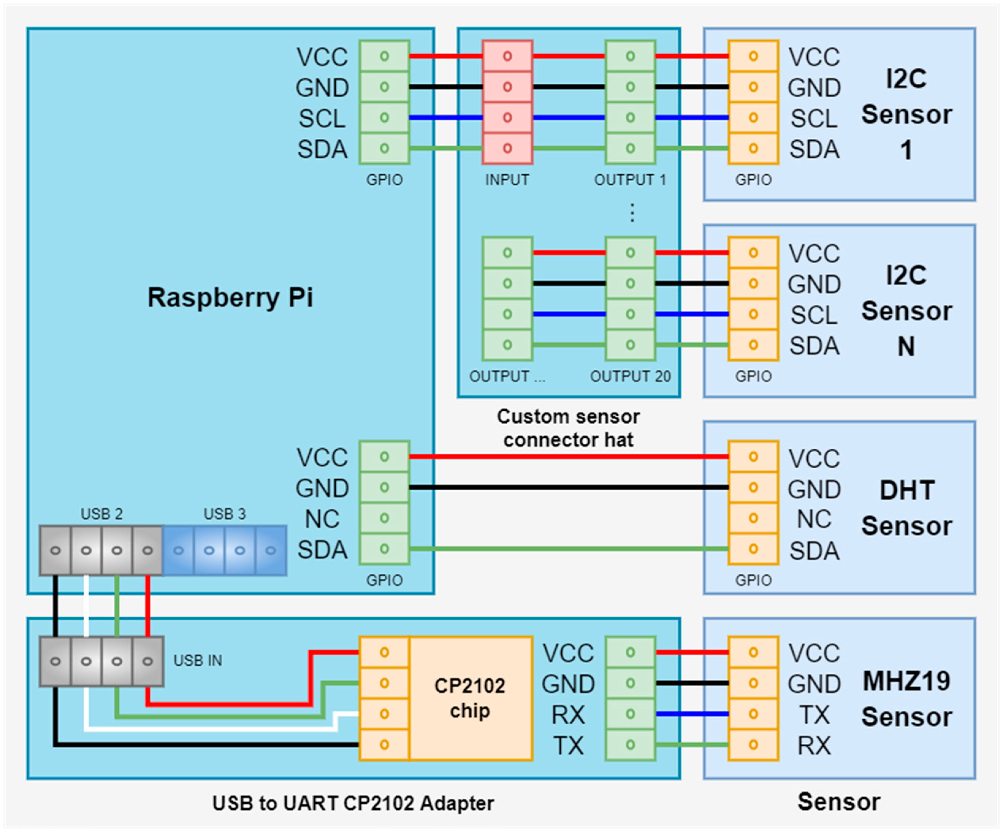
Most of the sensors are connected to microcontrollers via the I2C interface. Some of them have a proprietary interface using one wire or they use a serial communication. In
Figure 1, we can observe a generic schema of sensor connection to a Raspberry Pi [
11].
The schema can be applied to all microcontrollers, in general. For example, the ESP8266 that we are using is a small board and does not have a 5-volt VCC, and it has only two IO ports that can be used, so we can use only one type of interface at once. Some sensors require 5-volt VCC; they have the IO ports working with 3.3 volts, and in case of failure, they can burn the GPIO ports of the controller. In this case, is recommended to protect the GPIO ports with some resistors or you can use an adapter in case you are using a serial communication. As we can see in
Figure 2 and
Figure 3, some sensor modules and adapters already have integrated protections.
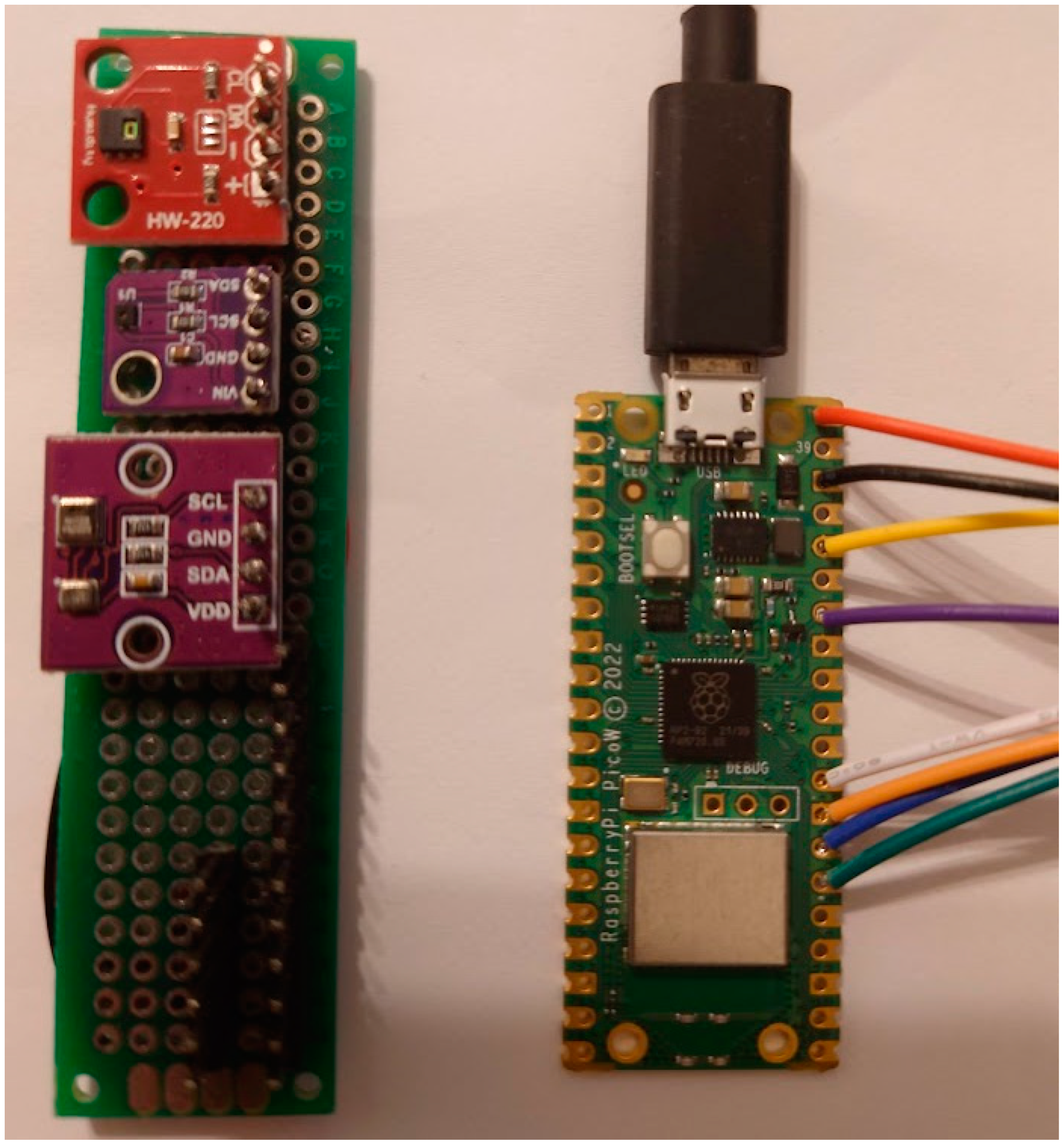
In
Figure 2, we can observe a picture of a Raspberry Pi Pico W and the custom adapter where we wired four temperature sensors. The sensors are arranged on three boards, the red board having an HTU21D sensor, followed by an SHT40, and the last board having two sensors, a BMP280 and an AHT20. We are using a module like this when we calibrate the temperature sensors attached to a single board computer such as Raspberry Pi due the fact that those powerful microcontrollers are dissipating heat, and the sensors attached to them are reading wrong values of the ambient temperature. The wiring allows us to move the sensors at about 20 cm away from the microcontroller. In this way, we make sure we can obtain relevant data, closer to reality. Moreover, we are using a combination of sensors because each sensor can have a small error, they are built by different manufacturers, and they use different technologies. In
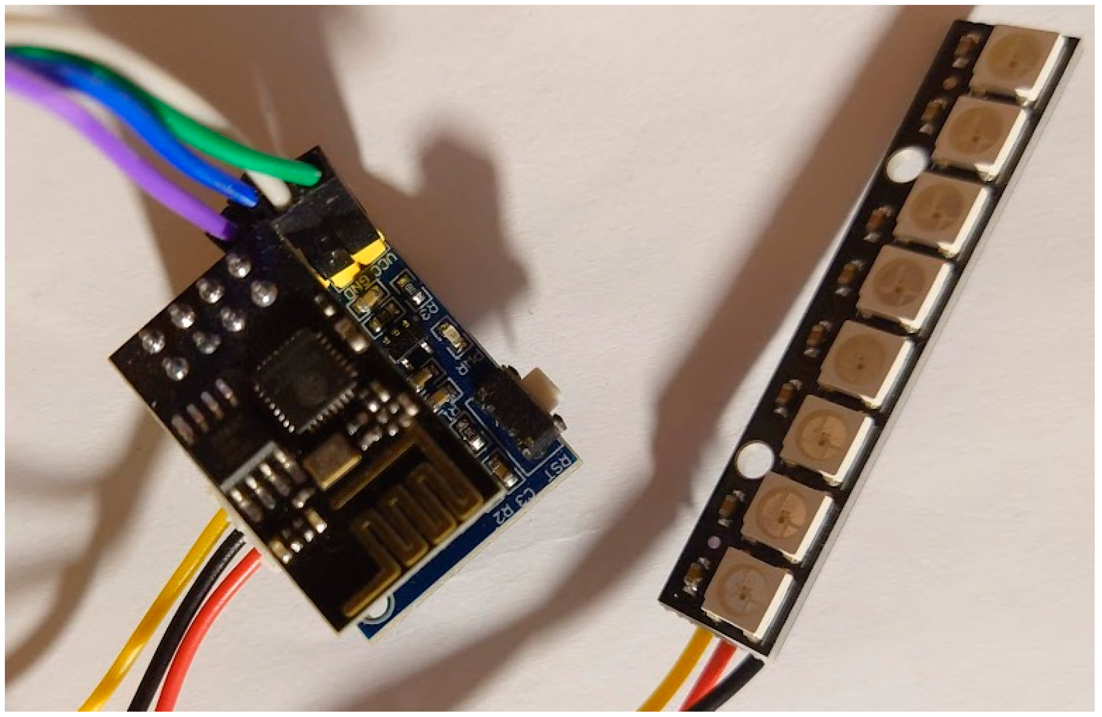
Figure 3, we have an ESP8266 with eight GPIO pins used to control the LED matrix. This ESP8266 can be found in different implementations, with eight pins like in this example or with more, in general with 26 pins if the board includes a screen or up to 30 pins without a screen. Some boards integrate a camera connector, where you can plug in a camera with a resolution of up to 2 megapixels.
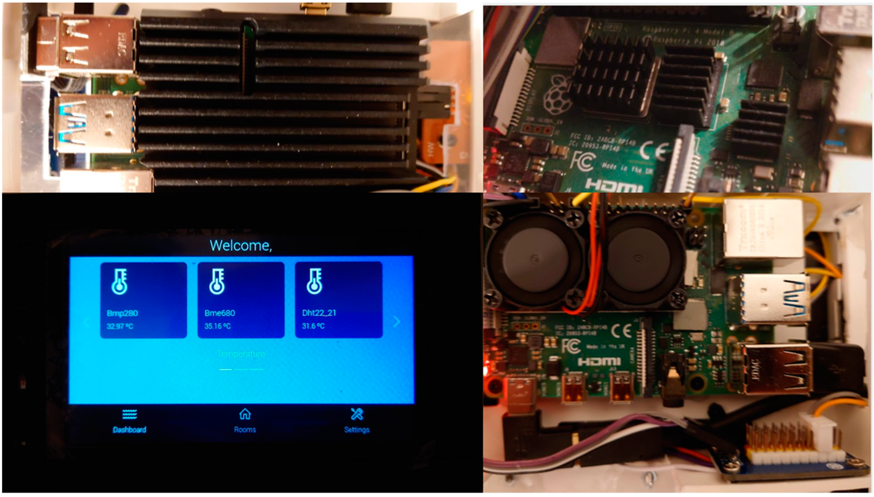
In
Figure 4, there are three examples of cooling methods we tried to use for Raspberry Pi boards and the first version of the web interface running on a 5-inch screen [
11].
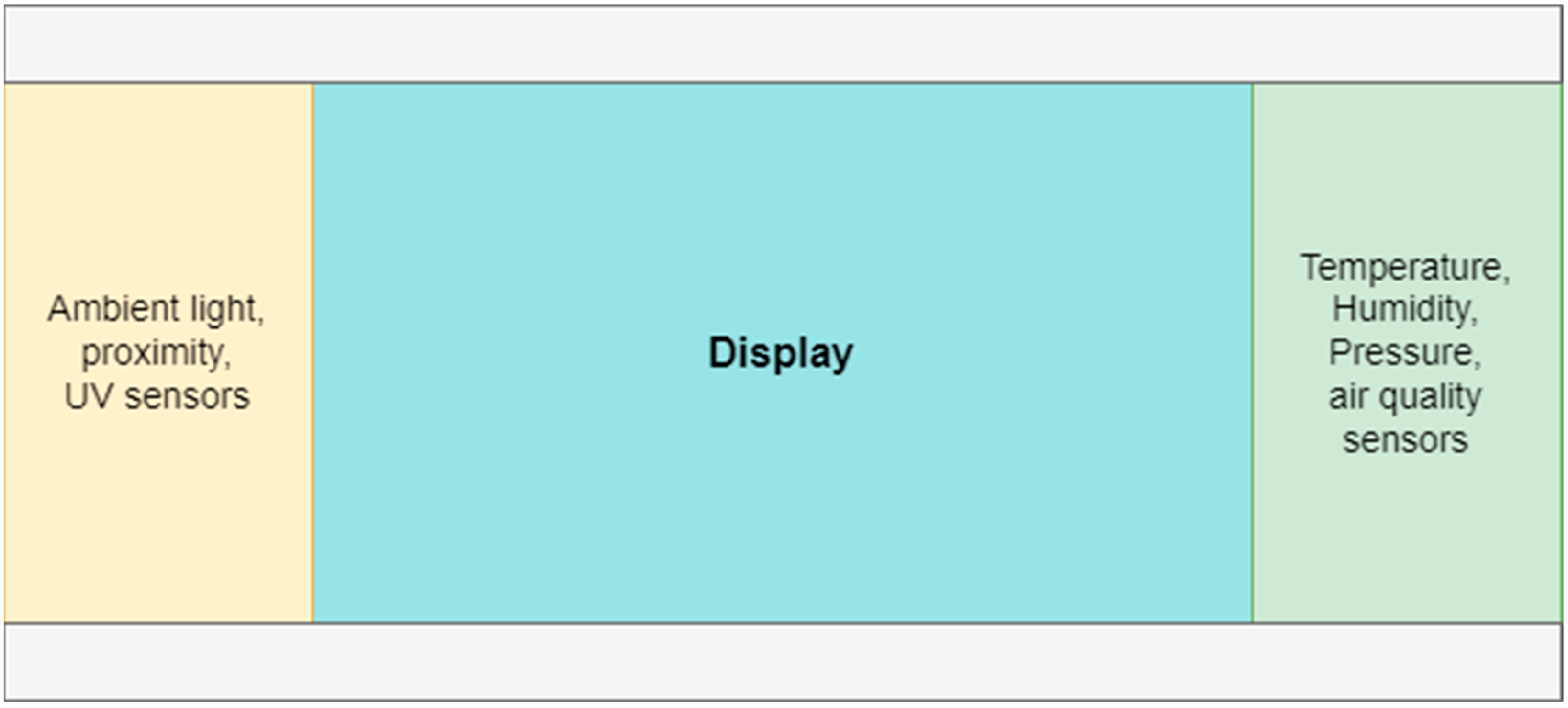
In our research, we noticed that the temperature readings are not closer to reality because our case design was wrong. We put the sensors closer to the Raspberry Pi, and because the CPU generates a lot of heat, the data can include errors of more than 5° Celsius in the case of temperature sensors. Some manufacturers split the cases into two modules, but they are still wrong. For example, we can find nice, small products that have a traditional size of a normal European wall switch or plug adapter, 86 mm by 86 mm. One part contains the relays and the power supply, while the other part contains the screen, the microcontroller, and the temperature sensor. The problem in this design is that the screen and the microcontroller generate enough heat to modify the output of the temperature sensor by 4° Celsius, depending of course by the ambient temperature. We studied this problem a little, and our final Raspberry Pi design includes the temperature, humidity, and pressure sensors in a separate compartment on the left or right side of the screen. The microcontroller is installed in a compartment which will be inside the wall, while the screen box is on top of the microcontroller box, and the left and right sides of the screen are not in contact with a heat source. In
Figure 5, you can see the box containing the screen and sensor compartments. The temperature, humidity, pressure, and air quality sensor compartment must have a very good ventilation, so it must have holes on the right side. If we want to provide a good air flow for the microcontroller, we can have holes in the compartments marked in gray.
1.2. Custom Smart-Home Software Overview
We are using multiple types of microcontrollers, but we can categorize them into two categories: single-board computers (SBCs) and single-chip computers (SCCs). We use SCCs with sensors connected to transmit the data from sensors to a backend or to control the microcontrollers from the main SBC. For example, ESP8266 is used to send data from a Raspberry Pi Pico over Wi-Fi or to control ambient lights in a room, as we saw in
Figure 3. It has a small configuration backend, where you can specify the Wi-Fi network and the main microcontroller to send data. If we use a USB-to-serial adapter, we can also configure it via serial interface.
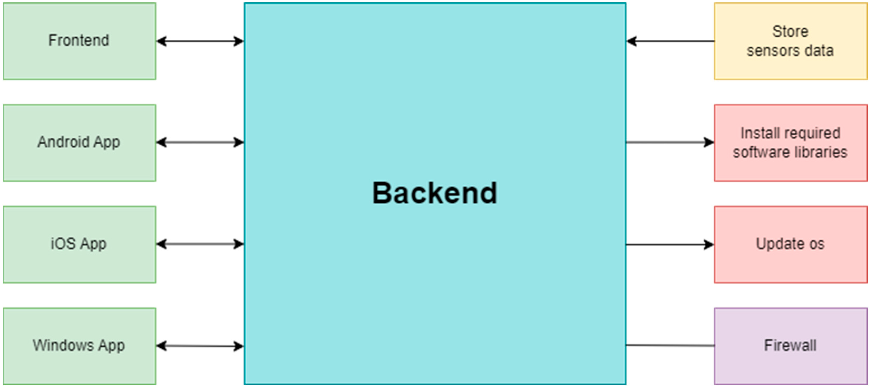
The backend is written in Python, and it is responsible for all the communication between the main board, sensors, other microcontrollers, and client applications. We can observe in
Figure 6 the main responsibilities.
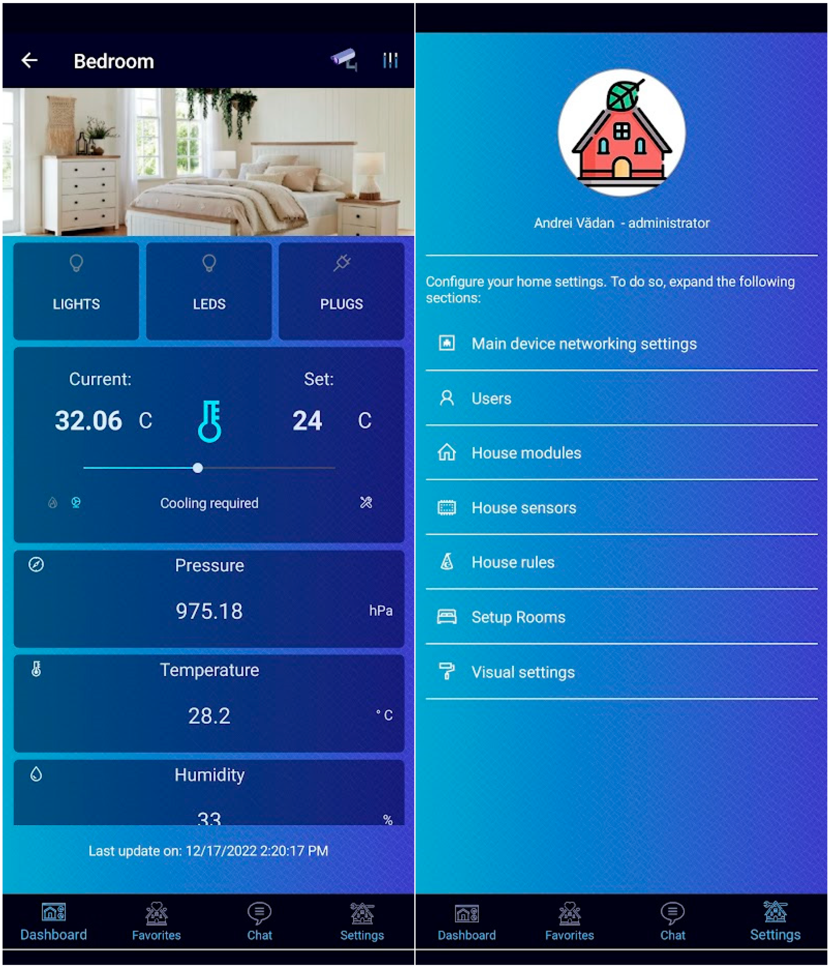
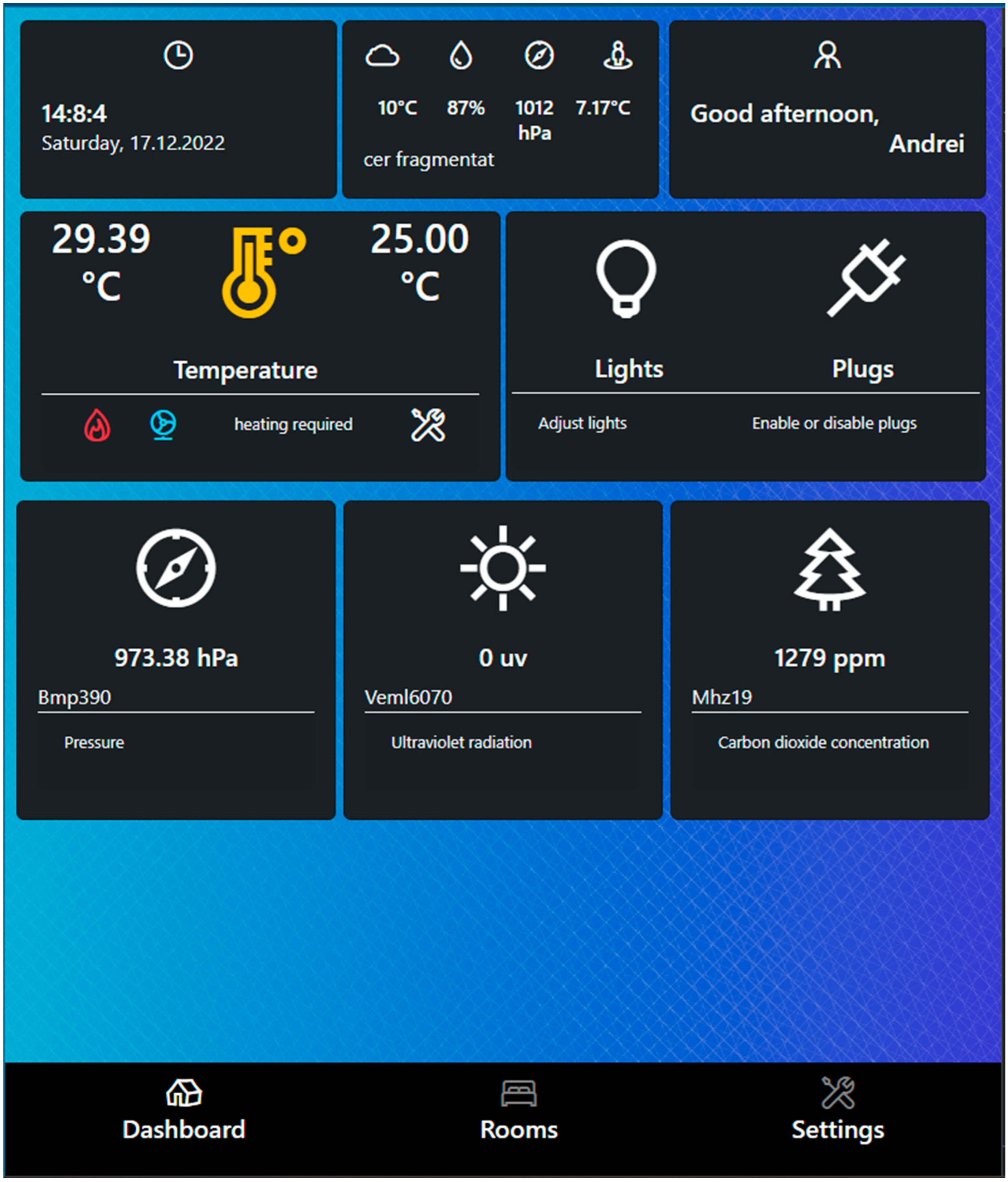
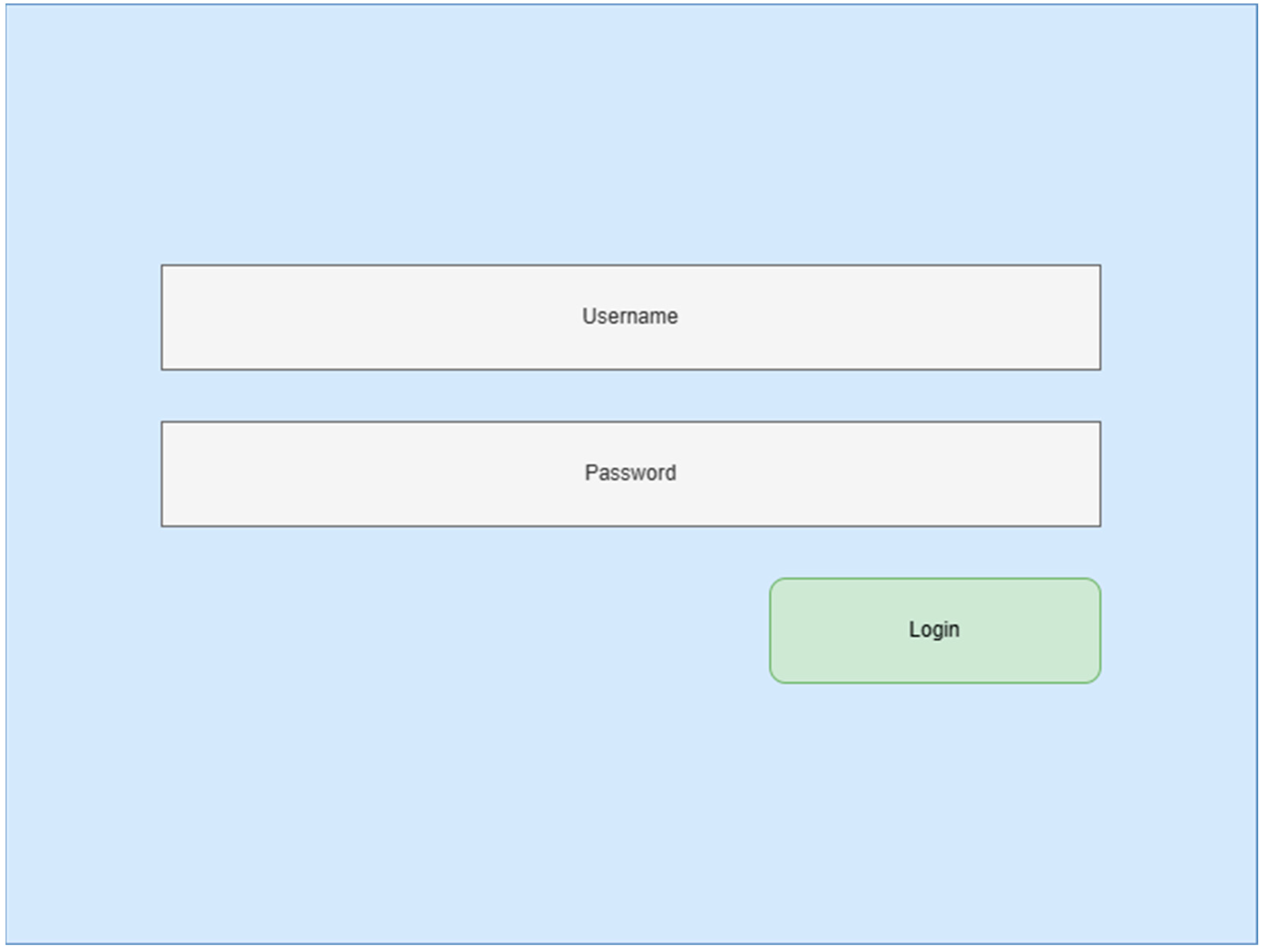
On the left side of the diagram, in the green boxes, we have the frontend, which consists of a web interface launched directly when the SBC starts. The main screen of the interface is presented in
Figure 7. We can see the rooms configured in the entire system and have an overview of sensor data. We can also see different parameters of the microcontroller, and in future the user will be able to configure it. At this point in time, the configuration of the microcontroller is possible only from other clients, such as Android, iOS, or Windows client. The architecture of the system can be considered a generic one and is similar to what other researchers are building in their IoT systems [
12,
13].
The Android, iOS, and Windows applications, exemplified in
Figure 8, are built using Xamarin and interact directly with the main module, which we configure in the application itself. The main module can be represented by any SBC microcontroller. A microcontroller can be used to define multiple rooms, and since we can use wireless sensors, we can choose what sensors are present in a room. The backend has a redirect endpoint which is responsible for getting data from the correct module. Each module is automatically configuring sensors found on the I2C interface or directly connected via USB or serial at each startup. In configuration, we have a property that sets the I2C address of the sensor and IP address of the module where the sensor is connected, so in this way, we make sure that we retrieve data for correct sensor, even if we are using the redirect endpoint. However, the configuration of the rooms is stored only on the main module. Under the ‘Main device networking settings’ section from the client application, you can define a web address, so you can access the backend via the internet. As a result, all endpoints that are not defined will redirect you to a 404 page. As a security feature, if someone tries bad endpoints multiple times, the connection to that machine is denied, and that person is no longer able to reach the module. In future, we plan to also encrypt the requests data for extra security.
The backend is started at the system boot, via a ‘cron’ job which is executing a script. The script starts a browser with a loading screen and, in the background, checks for operating system updates and backend dependencies. If some requirements are not met, the script will automatically request an operating system update and will install the required updates. In future, we will also finish the automatic update of the system and backend. For this feature to be completed, we also need a backup mechanism. For future development, we would like to add features such as security cameras. The backend should be able to save pictures from the security cameras. At this point in time, we are able to see a live feed from the security cameras using RTP protocol.
1.3. Design Patterns and Automation Frameworks
In general, when we discuss testing an entire system, we must have automation testing in mind. Complex systems or applications require custom automation frameworks because current software testing solutions might not cover all requirements. For mobile applications, such as native Android or iOS applications, we can use built-in tools, which are more powerful and provide better results in general, and of course, we can benefit from white-box testing or, in a worst-case scenario, gray-box testing. When we discuss applications built for testing or testing a website or API, we generally use black-box testing techniques. Further on, we will describe how to build a custom testing framework using simple techniques that will simplify the work, reduce the development time, and provide faster results when testing, no matter what technology we use. Of course, there are multiple applications built for automation, and you can probably apply our methods using these kinds of applications, but we did not try them. We will continue to focus on custom automation frameworks. We picked our smart-home system because it has a web interface, an API, and a mobile client, which means that we will present to you how we can apply this design pattern in testing a system with a complexity like ours. Because we are discussing a design pattern, we can choose any programming language that we desire, so we will show you some pseudo-code that should give you an idea about how you can apply the design pattern. When we refer to user interface testing, we are thinking about web, mobile, or desktop applications. First, we will present a small introduction about design patterns and Page Object Model, and then we will discuss Locate, Execute, Expect and its application in different scenarios.
When they design new applications or features, developers usually try to create an architecture of the application using design patterns. For the first time, the term design patterns appeared in building construction [
14], and in 1994, for the first time, four developers wrote a book about design patterns in coding [
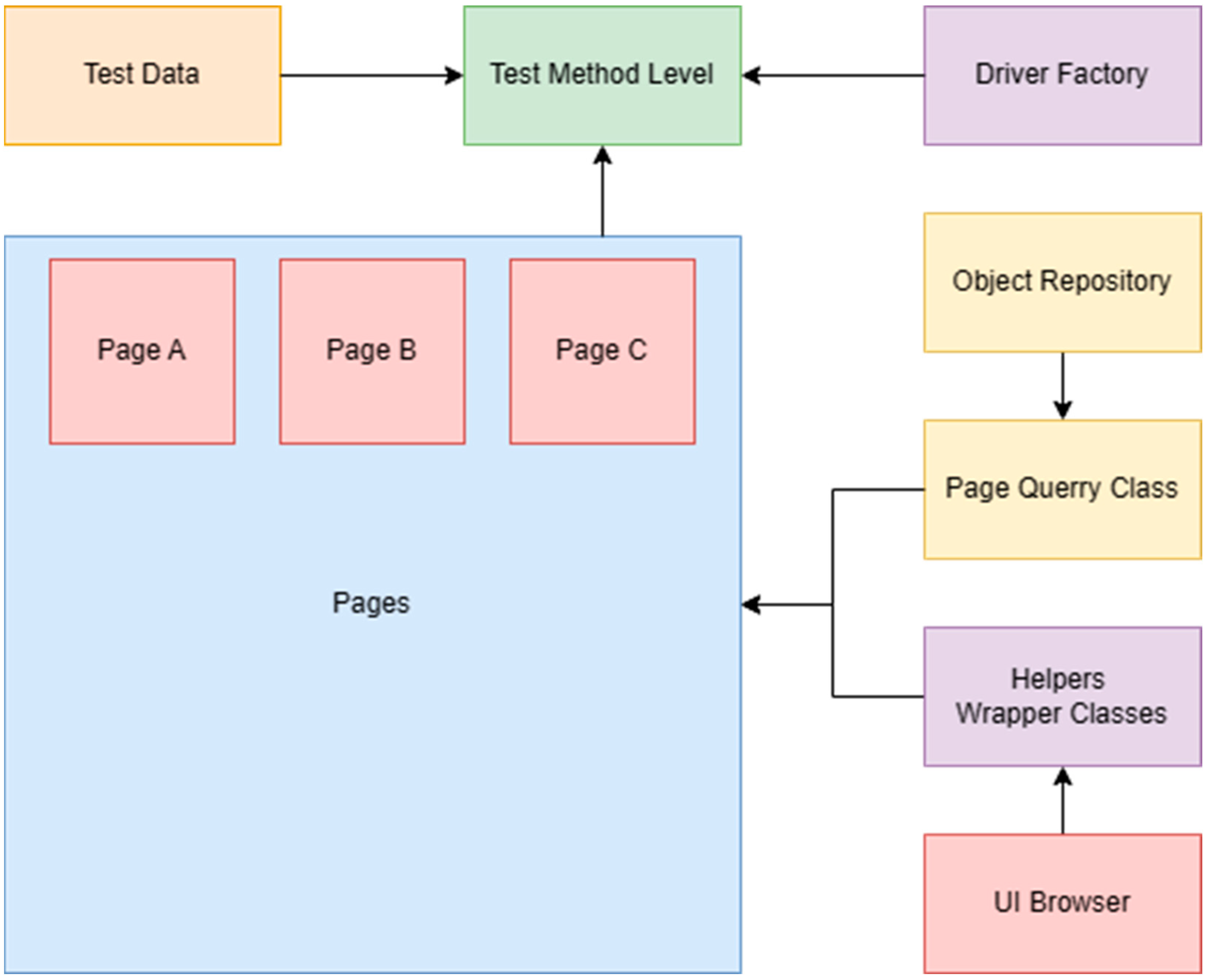
15]. Since then, in building custom automation frameworks, automation developers have used the Page Object Model design pattern. This design pattern has multiple code layers and is very complex. An example diagram can be found in
Figure 9.
The main issue with this design pattern is that most of the automation engineers implement it incorrectly, and instead of providing advantages, it usually ends up resulting in disadvantages. For example, on many occasions, we found people mixing object repository class with page classes and duplicate methods from Page A in Page B. Another issue is that these are also not able to create component pages. When a developer creates an application or designs it, he identifies the common components and defines them in code once, then he reuses them over and over again. The problem in automated testing is that a lot of automation quality assurance engineers are lacking in programming skills, especially the object-oriented programming ones. This means that they cannot identify correctly reused components by programmers and create a single page for the component, one class for steps, etc. To give you an example from a real-life scenario, we should imagine a media player that can play music from different sources. You can find this kind of media player in cars for example. A tester tends to create a separate page for each media source page, even if most of the components and behaviors are identical. For this kind of issue, instead of using the Page Object Model design pattern, we are going to show you how to use the Locate, Execute, Expect design pattern. We will present how to apply it in testing a smart-home system such as the one presented in the introduction. We will discuss testing web applications, user interface testing, and use it to test the API. Before that, we will shortly discuss design patterns and describe in a few words both Page Object Model and Locate, Execute, Expect [
16].
We can classify design patterns into three types: behavioral, creational, and structural. The behavioral patterns describe interactions between objects and focus on how objects communicate with each other. They can reduce complex flow charts to mere interconnections between objects of various classes. Behavioral patterns are concerned with algorithms and the assignment of responsibilities between objects. Behavioral patterns describe not just patterns of objects or classes but also the patterns of communication between them. These patterns characterize complex control flow that is difficult to follow at run-time. They shift your focus away from the flow of control to let you concentrate just on the way objects are interconnected.
Behavioral class patterns use inheritance to distribute behavior between classes. The most common design patterns are the Template Method and Interpreter pattern. Creational patterns are used to create objects for a suitable class that serves as a solution for a problem. They support the creation of objects in a system and allow objects to be created in a system without having to identify a specific class type in the code, so you do not have to write large, complex code to instantiate an object. Structural patterns define how classes and objects form larger structures. Structural class patterns use inheritance to compose interfaces or implementations [
17,
18,
19].
1.4. Page Object Model Design Pattern
There are many conceptual maps of what Page Object Model looks like, and in the following sentences, we will briefly describe its components or code abstraction layers, which were shown in
Figure 9 above. The Test Method level is the layer where test case is described using action and validation steps. This file handles all inputs and is responsible for data source binding. Page Factory is an optional layer, and it is used if you want to ‘pre-initialize’ the UI elements before run-time. This is done using Selenium ‘FindBy’ annotations. To do so, you need to create properties for elements of a page class and use an attribute to set the identifier that will be used to find the element. In this way, you will make an alternative of the ‘driver.FindElement(s)’ function from Selenium. In our opinion, the ‘FindElement’ function gives you more flexibility, and it is easier to find, wait, try to validate that an element is not in the page, or iterate through a list of elements. Page object classes and their methods represent each logical division of an application. For example, each page from the application should have its own page class. Of course, if we have multiple reused components, we can divide them into subcomponents, so we create a page for each subcomponent of a page. An example of this kind of usage is if we have a media player. The main controls are the same; instead of creating a page for music and a page for videos, we can reuse the player buttons, and we define a class for that. Driver Factory initializes the driver to provide support for testing. In Selenium, it is used to initialize the browser or to connect to a remote browser. For Appium, it can be used to connect to device for example. Object Repository is not always implemented by automation engineers, but it is useful. In this layer, you abstract the automation identifiers from the page class and keep all the UI element properties in a file that can be queried from an object repository class. This reduces maintenance time in case of application updates. Having an object repository adds another level of modularity to your solution and separates the object locators from the page classes. Helper or wrapper classes are very useful to create a class where you write wrappers or different functions. Implementing wrappers can help users to manage error handling, create smarter waits, timeouts, fail safes, or retries, but can also help with logging steps or errors. In the test data source layer, you can define a data source for the test method and use test data from a file such as a CSV, XML, Excel, or even a SQL database. Data-driven testing is vital to cover more terrain by executing multiple test iterations of the same test case with different data scenarios, saving code and time [
17,
18].
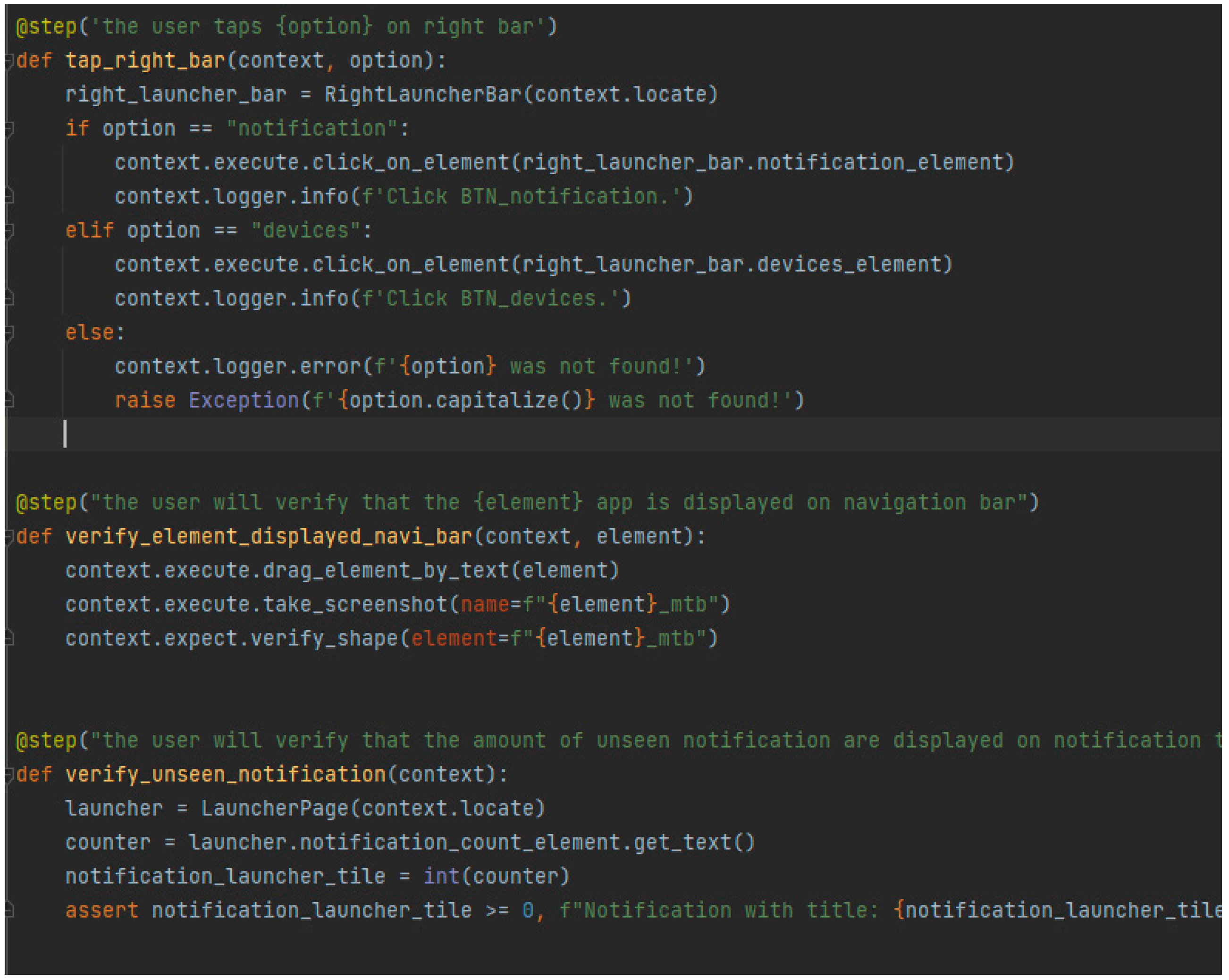
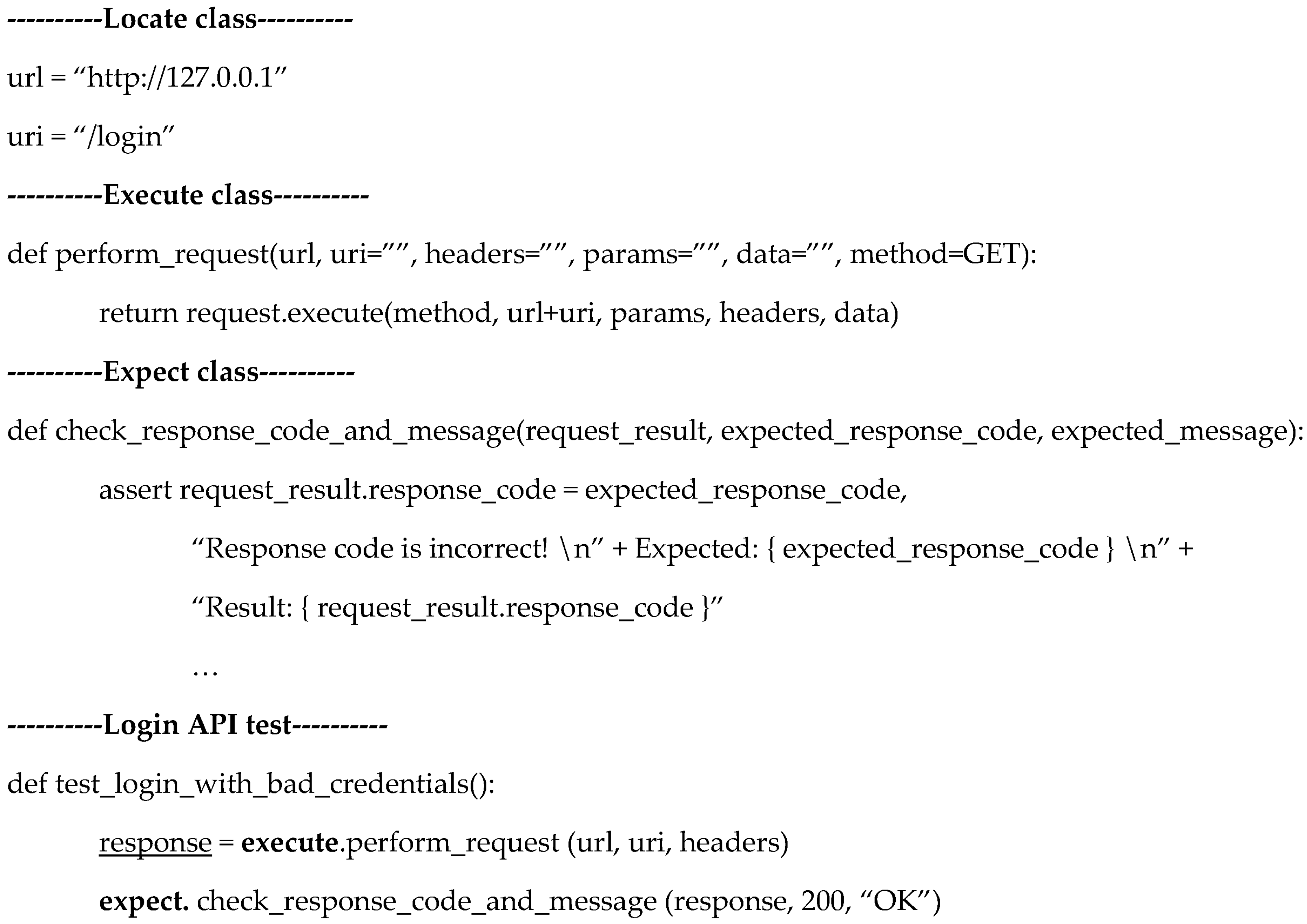
1.5. Locate, Execute, Expect Design Pattern
The Locate, Execute, Expect design pattern has less code layers than POM. We have a layer called Locate, where we define the methods to identify the UI elements and the automation identifiers of the UI elements. It is recommended that you create files for each page and define identifiers in a page or create nested dictionaries for UI elements. To give you a concrete example, if you go back to
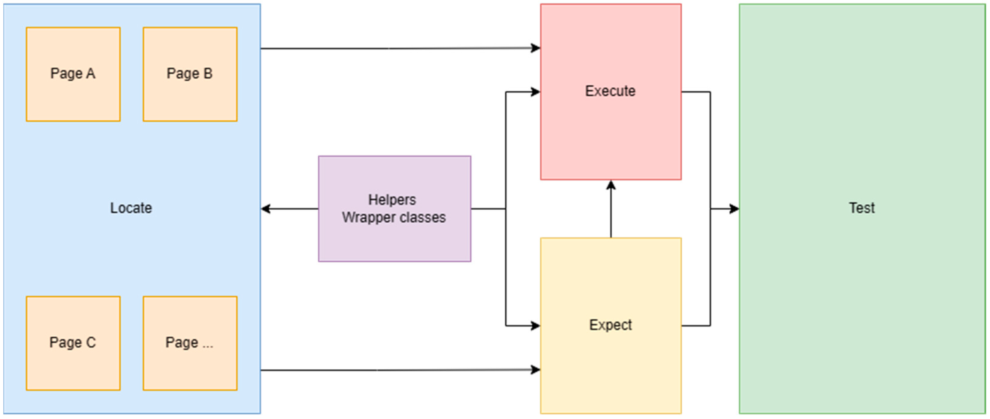
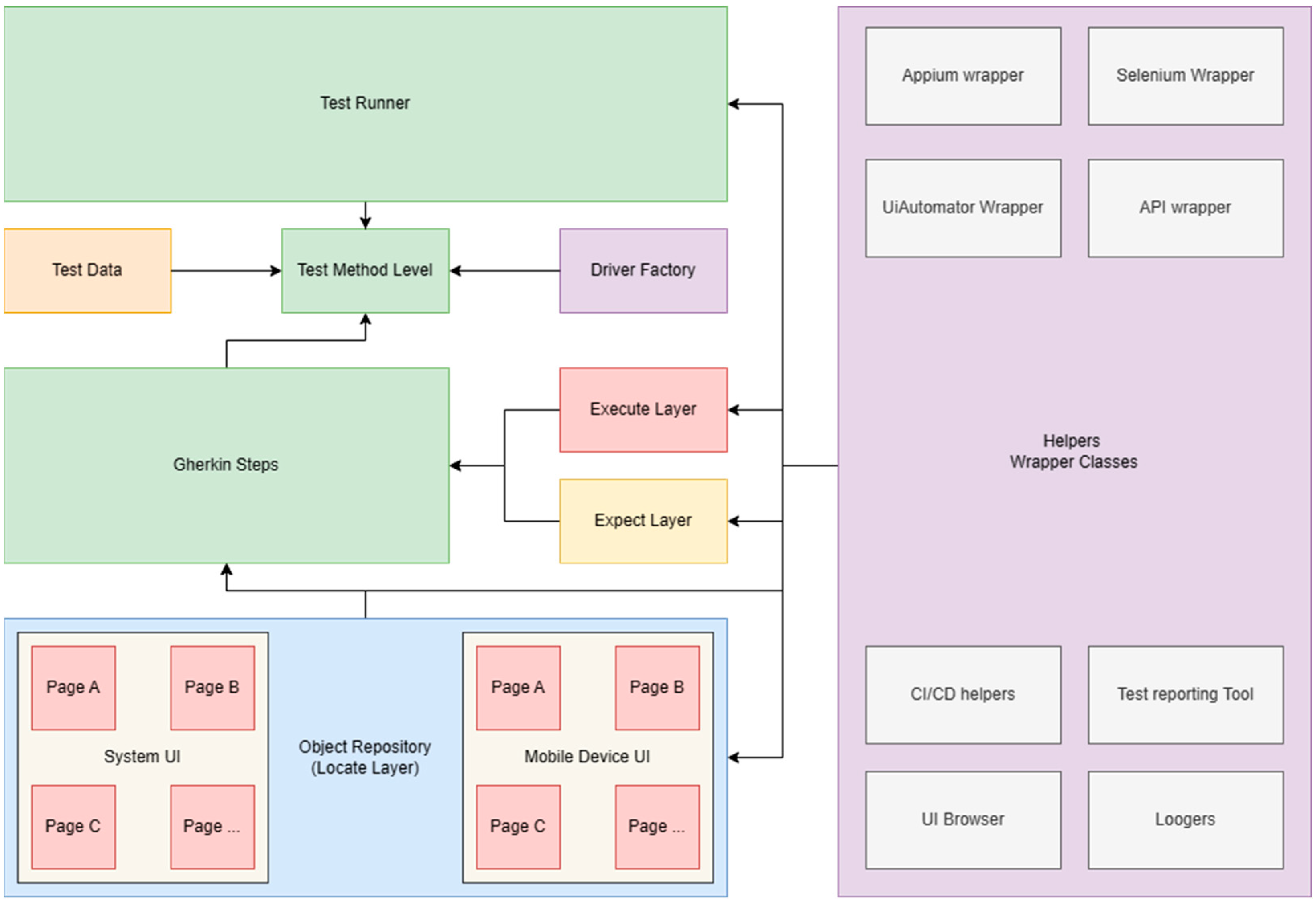
Figure 8, you will see some of the mobile application screens. The application has four main screens, ‘Dashboard’, ‘Favorites’, ‘Chat’, and ‘Settings’. When we click on a room on the ‘Dashboard’ page, we open a page that displays information collected from sensors, and we can perform different actions and open other pages. For each page in the application, we create a page class in code, and we describe the automation identifiers. For menu, we can create a separate page as we will normally do using POM. In the ‘Locate’ class, we will create a nested dictionary, where the main dictionary will have multiple sub-dictionaries. The ‘Execute’ layer contains a class which should contain main methods that perform actions or handle waits. If we are testing systems and we have a large number of methods, we can split the code into multiple classes based on the pages we are using or applications. The ‘Expect’ layer is similar to ‘Execute’, but here we put just the verification steps. One important thing to mention is that the verification layer does not include methods from the action layer, but the ‘Execute’ layer can include methods from ‘Expect’. In this way, we avoid circular dependencies. In
Figure 10, we can notice the generic diagram of the LEE design pattern [
16].
If it is a must, we can include helper classes, but those are not considered a part of the LEE. If we want to combine this design pattern, we can also use it along with POM without any problem. This is because the ‘Locate’ layer is basically represented by the object repository and page classes, we need to reuse methods defined in an action and verification class. In this way, the methods from page object classes are using generic methods and the maintenance of the code is much simpler. Having a combination of those design patterns is not ideal however, because when used with a combination of wrappers, they can result in a lot of problems, especially with interpreted programming languages. Additionally, when we try to debug, we go from method to method, and for beginners, it can be a hassle.
3. Results
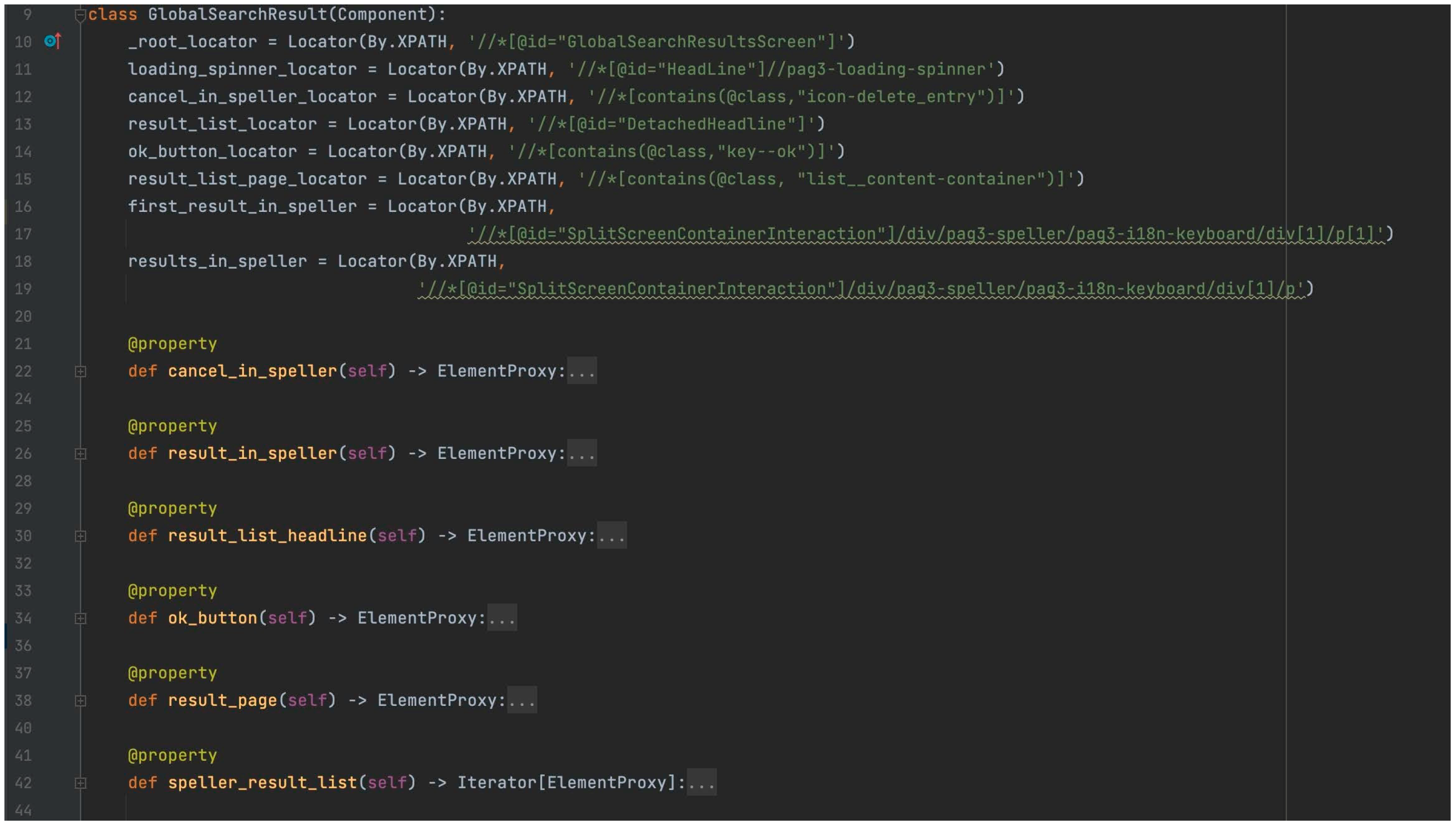
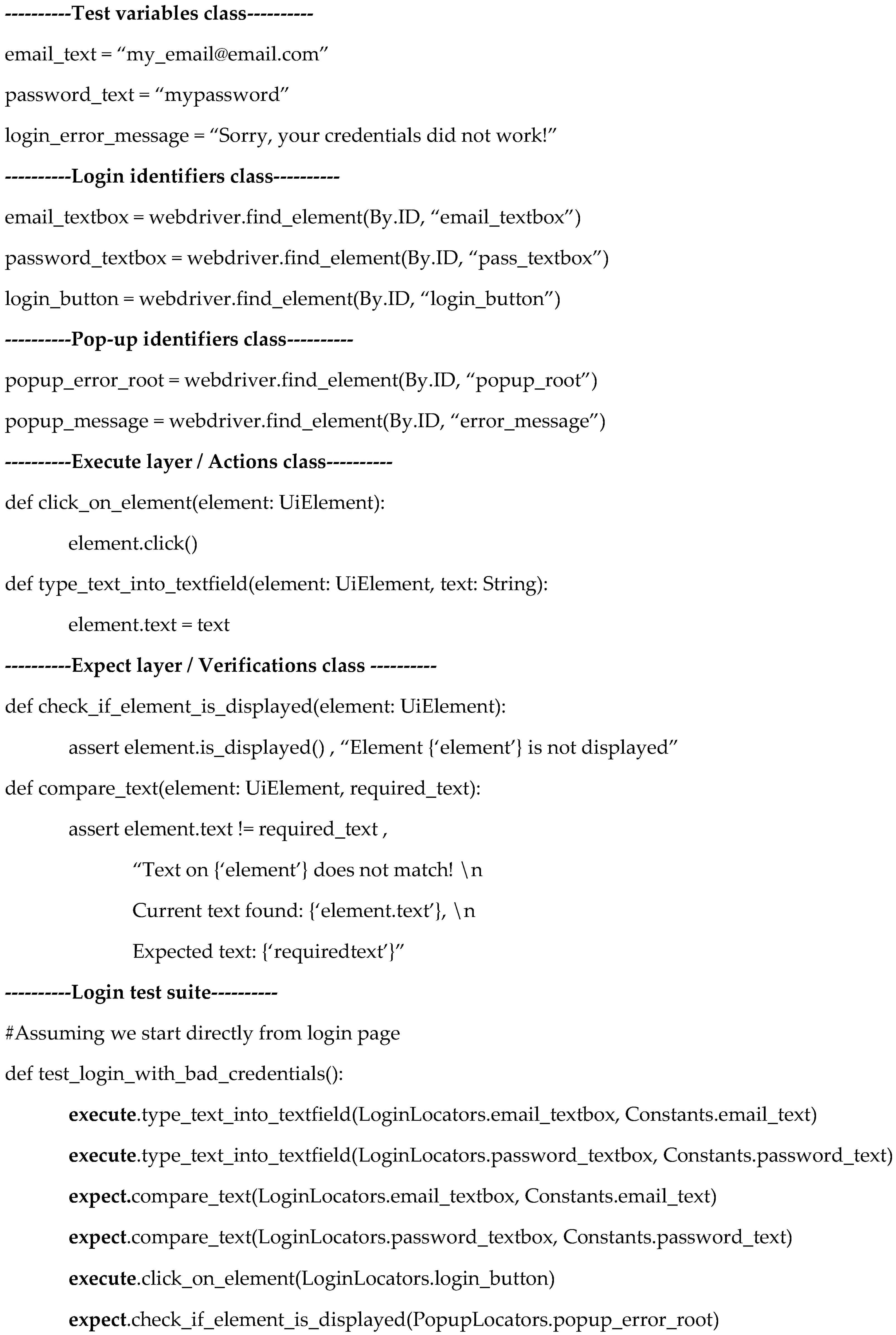
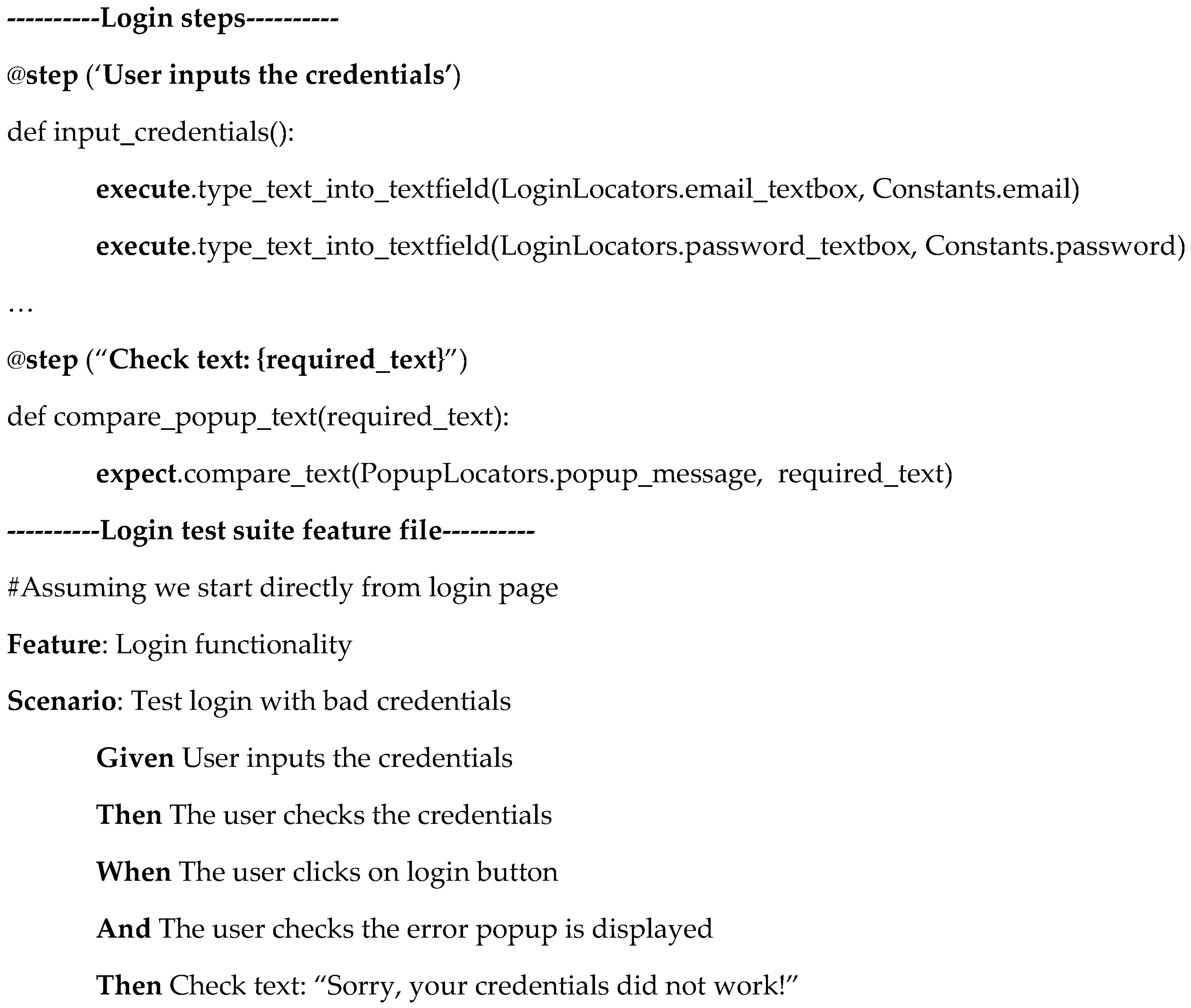
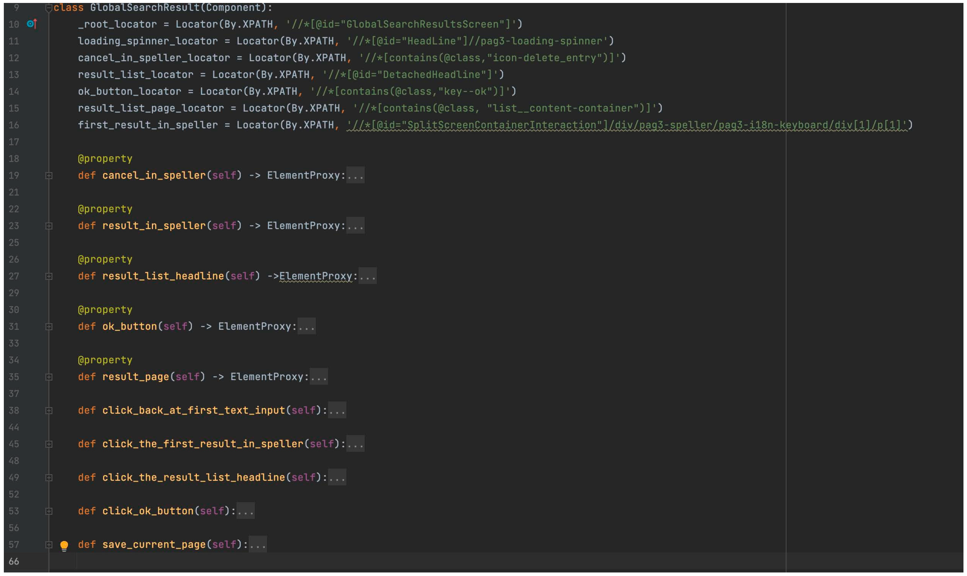
In
Figure 17, we exemplified the code of a page class from the ‘Locate’ code abstraction layer and in
Figure 18 the same class using POM. Screenshots are taken at different stages of development of our automation framework and should clearly point out how the LEE design pattern reduces confusion about using POM correctly. Tidiness of the code after using LEE is shown in
Figure 19. We had a similar approach with our smart-home system testing, and the efficiency of using LEE increases with the level of complexity of the project.
The main difference comes in the method definition inside the page class. Using LEE, this is avoided, and the code is much cleaner and easier to read. In
Figure 18, we have four methods doing in essence the same thing, performing a click on a specific element. Imagine if we test a system with more than 100 views or pages, and we use the approach shown in
Figure 18. This is a perfect example of how we can increase the reusability of methods using LEE. In
Figure 19, you can notice how we applied LEE in one of our automation frameworks. However, to make sure that we have a good coding standardization, for example, the name of the first function should be renamed. Functions or methods describing actions must have in their name, in general, the type of action, the element, and where is performed. The verification methods must contain in general only verifications, and the second method is an example of bad usage. The ‘drag_element_by_text’ and ‘take_screenshot’ can be defined in two different steps rather than being included in the verification step. We can definitely agree that it is much easier to spot the mistakes in the step definitions when we apply LEE in a project.
We applied the LEE design pattern for testing several systems and applications since 2018. The initial work was conducted in testing mobile applications for Android and iOS using native solutions, implemented in Kotlin and Java, respectively, using Swift. On the initial project, there was a team of about five to ten quality assurance engineers for manual testing and two automation engineers. By applying the design pattern in the automation framework, at that point in time, we built an automation framework that can be used easily by the manual testers and help the managers to understand what we test and what the results are. Some of the manual testers started to write automation tests, and they were able to do it very easily. Some of them started to code for their first time and became independent in writing tests after 3 months. This was possible because we developed most of the methods needed, and the manual testers learned how to use them.
Then, we started to work on an IoT project, presented briefly in this paper, to study how we can apply this design pattern to other scenarios, such as backend and web user interface testing. The project also included a client application which is cross-platform, and we successfully tested the design pattern using Xamarin technologies and C#, not only the web version and the API.
While working on the IoT project, we applied the design pattern in testing automotive embedded system, to be precise, the infotainment system of a car manufacturer. In this project, previous engineers did not correctly apply the POM design pattern, and this generated a lot of duplicate code, which was hard to maintain. Because the project tests the entire system, there are more than 100 user interface pages, containing sometimes more than 20 elements and 10 methods. The manufacturer installs the same infotainment system in multiple types of cars, and the tests are executed for each car type. By using this approach, we managed to merge the code into just one piece and reduced the maintenance time significantly. One important aspect is that when a new test is automated, the time is reduced, and the test in most cases can be applied to all car types, so we reduced the development time by more than 50%. By applying LEE, we managed to make the code reusable and cleaner, integrate new colleagues more easily, and obtain smoother transitions from one software version to another. However, we had some challenges on this project, due to the wrappers created over generic functions of Selenium, Appium, and the fact that Python is an interpreted language, and we need to assure that we are using the correct type of objects. Overall, applying it to new projects or to existing projects can bring benefits on a longer term. We used the wrappers created initially on a second project, and the effect was that we had a mature framework built in a few days and reused the generic methods to implement more than 30 test cases in a month, everything made by just one automation engineer. This means that once you create your main structure using LEE, you can reapply it to any project using the same technology, no matter how sophisticated is.
One of the intrigues of the colleagues was that we can apply this principle to software development in general, but we could not identify a scenario where it excels and can be better than current design patterns that we already have at our disposal. You might encounter issues if you tend to create multiple code abstraction layers and you use interpreted languages like Python, but those issues rarely occur and can be fixed easily by specifying the type of parameters or correctly applying principles of object-oriented programming.
In
Table 3, we wrote a comparison between LEE and POM and relevant points for a test automation framework and test automation team. Some of them are also noticed due to overtime usage and not necessary described in this paper.
4. Conclusions
LEE design pattern is very good when applied in testing, especially on custom automation frameworks, because we are able to use it in most common scenarios, such as testing a website, a mobile application, or to test an API with high efficiency. It helps automation engineers to maintain clean code and ease the integration of newcomers. It can easily replace POM or other design patterns used in current projects and increases the reusability of common methods. Integration with the continuous integration or continuous delivery systems is very easy because it does not require additional plugins.
In future, we want to extend the main usage of the design pattern and study how it can be applied in unit testing for example. Additionally, to prove the efficiency of a framework using this design pattern, we would like to monitor some parameters in a team of test automation engineers. To do this, we must take in consideration the most important aspects, such as the time needed to implement a test case, the time spent for maintenance, and methods reusability, for example. We also want to study if there is an impact in what type of network we use in our smart-home automation, similar to what the authors of ‘Comparative Evaluation of the Performance of ZigBee and LoRa Wireless Networks in Building Environment’ [
20] discovered, and there is an impact of what programming language we used for testing the same system, by trying to apply algorithms and methods presented in ‘Performance Evaluation of C/C++, MicroPython, Rust and TinyGo Programming Languages on ESP32 Microcontroller’ [
21].
There are multiple automation testing programs on the market, and because of this, we want to study if we can apply this design pattern in an already built program for automation testing.


