Review

Multilayer Ceramic Capacitors: An Overview of Failure Mechanisms, Perspectives, and Challenges

by
Khaled Laadjal
* and
Antonio J. Marques Cardoso
*
CISE-Electromechatronic Systems Research Centre, University of Beira Interior, Calçada Fonte do Lameiro, P-6201-001 Covilhã, Portugal
*
Authors to whom correspondence should be addressed.
Electronics 2023, 12(6), 1297; https://doi.org/10.3390/electronics12061297
Submission received: 3 February 2023 / Revised: 26 February 2023 / Accepted: 3 March 2023 / Published: 8 March 2023
(This article belongs to the Special Issue Feature Papers in Industrial Electronics)

Abstract

:
Along with the growing of population and social and technological improvements, the use of energy and natural resources has risen over the past few decades. The sustainability of using coal, oil, and natural gas as the main energy sources faces, however, substantial obstacles. Fuel cells, batteries, and super-capacitors have the highest energy densities, but due to their high-power density and rapid charge-discharge speed, regular dielectric capacitors are becoming more popular for pulsed power applications. High electric breakdown strength and high maximum but low-remnant (zero in the case of linear dielectrics) polarization are necessary for high energy density in dielectric capacitors. The high performance, multi-functionality, and high integration of electronic devices are made possible in large part by the multilayer ceramic capacitors (MLCCs). Due to their low cost, compact size, wide capacitance range, low ESL and ESR, and excellent frequency response, MLCCs play a significant role in contemporary electronic devices. From the standpoint of the underlying theories of energy storage in dielectrics, this paper emphasizes the significant problems and recent advancements in building extremely volumetric-efficient MLCCs. Following a thorough examination of the state-of-the-art, important parameters that may be used to improve energy-storage qualities are highlighted, such as controlling local structure, phase assembly, dielectric layer thickness, microstructure, conductivity, different failure modes, and the specific performance during the failure mechanism. The summary of some conclusions on the impending need for innovative materials and diagnostic methods in high-power/energy density capacitor applications appears at the end of the paper.

1. Introduction

Ceramic capacitors, film capacitors, and electrolytic capacitors are the three basic types of capacitors. The dielectric, structure, terminal connection technique, use, coating, and electrolyte may all be used to further classify each category (only for electrolyte capacitors) [1]. Since the number of stored charges is mostly dependent on the dielectric material, the dielectric categorization is the most used. Table 1 displays some of the above categories of dielectric properties [2,3].
As it was previously possible to establish, the properties of the dielectric dictate how the capacitor behaves. This is generally the case for all capacitors, however for exceptionally high-power capacitors, the permeability of the plates, tabs, and connections may also be used to calculate the highest peak current of the capacitor.
Table 1 makes it abundantly evident that the various kinds of capacitors have varied properties, thus which capacitor to use relies on the properties of the circuit in which it will be used. The following are a few of the most crucial factors to take into account while making a decision [1]:
Ratted voltage, capacitances, price, volumetric efficiency, consistency and dependability of capacitances, longevity, and power density.
Current ripple ratting and maximum peak current.
Temperature range, insulating resistance, and leakage current.
Capacitor performance and resonance frequency (capacitance dependency with frequency and temperature, as well as its internal resistance).
The most common type of capacitor in electronics is a ceramic one, and the most popular type of these is called a multilayer ceramic capacitor (MLCC). Many electrical products, including computers and cell phones, use MLCCs. Three kinds of commercially available dielectrics can be distinguished: Categories I, II, and III [4].
Titanium oxide, which has the lowest dielectric constant of the ceramic technologies, is used as a dielectric in Class I dielectrics, which are also known as temperature compensated dielectrics (Table 1). These capacitors are useful for several electronic systems circuits, including snubber circuits and soft-start circuits, due to their poor volumetric efficiency and tiny capacitance values (100 nF). Along with being relatively stable with voltage, temperature, and time, the capacitance additionally has a low dissipation factor [5].
Class II dielectrics, also known as high dielectric constant materials, use the high dielectric constant material barium titanate as a dielectric (Table 1). These capacitors are produced due to their compact sizes and high capacitance values. Their dissipation factor is therefore relatively large, and their capacitance tends to be unstable in response to voltage, temperature, and time [2,3,4]. The maximum capacitance variation over a temperature range is determined by the final digit of the three-character alphanumeric code used to describe Class II dielectrics. For instance, because the maximum temperature change for the X5R, X7R, and X8R’s capacitance is 15%, these devices are recommended for use in power electronics circuits. Both classes have higher dielectric resistance and lower dissipation factors when compared to Al-caps, but they have worse properties when compared to MK capacitors. Class III dielectrics, which have the highest capacitance and maximum volumetric efficiency of the three classes, are used to construct barrier layer capacitors. However, temperature, voltage, and frequency have a significant impact on them. Additionally, they operate at a voltage of about 25 V. Class III ceramic capacitors are frequently used in bypass coupling when dielectric losses, strong insulation resistance, and stability are not required [4].
Class II and class III capacitors, which tend to have greater dielectric constants and smaller breakdown fields, are therefore better suited for low-voltage applications, particularly where considerable capacitance is needed. The failure of ceramic capacitors during dielectric breakdown, which renders the device worthless, is another pertinent component of these devices [6].
For power devices, Cer-aLinkTM, a new ceramic capacitor technology from EPCOS, may be the ideal option. Recent research has shown that this technology can be particularly useful in the DC-link of voltage source inverters because of its promising properties, including low losses, rising capacitance with applied voltage, low series inductance, and high-capacitance density [7,8].
The necessity for portable electronic devices that can be connected to high-speed, high-transmission-capacity networks has increased, as shown by words like “digital nomad”, “ubiquitous computing” and “internet of things.” These breakthroughs have accelerated research on electronic components with high performance, great reliability, and low power consumption. The multilayer ceramic capacitor (MLCC), which is one of them, is the most significant passive element capable of storing and releasing electrical charge. For resonant circuit applications, MLCCs provide excellent stability and low losses, as well as great volumetric efficiency for buffer, by-pass, and coupling applications [5,9,10,11].
Prior studies, including those conducted by the authors of [12] and [13,14,15,16,17,18,19], have evaluated an MLCC’s dependability under high-acceleration impacts, mostly focusing on structural failure for an MLCC’s electrical, mechanical, and thermal interaction [20]. Using a multiscale homogenization modeling method, the authors of article [21] created a finite element simulation model to describe the structural characteristics of multilayer ceramic capacitors. In [22], it was discovered that the electric field distortion brought on by the impact-driven deformation of an MLCC can quickly lead to ceramic capacitor failure. This was demonstrated using the analogous mechanical model. Through a dynamic experiment with a high-overload impact, an MLCC failed. The impact of this failure on an advanced system was then examined.
Energy-storage and conversion technologies are envisaged for use in practical applications because they have a wide operating temperature range, are inexpensive, have a high energy density, a high-power density, and a high conversion efficiency. Figure 1 illustrates the energy and power density requirements for typical energy-storage systems [23].
Dielectric capacitors offer ultra-high-power densities > 10 kW kg−1 in comparison to conventional energy-storage devices. As a result, they have ultra-high charging and discharging speeds and may start releasing accumulated energy in a nanosecond or microsecond time frame scale, allowing for exceptionally high pulse power. They also offer beneficial qualities, including an extremely long cycle life, dependability, and safety.
Dielectric capacitors are therefore essential for the development and application of third-generation semiconductor devices. These components are also utilized in high-power energy-storage and pulse power systems, which include electromagnetic weapons, advanced medical equipment, electric and hybrid vehicles, and smart grids [24,25]. However, the energy density of currently available commercial polymer dielectric capacitors is quite low (0.1 Wh.kg−1), leading to relatively large and heavy energy-storage and pulse-power devices.
For instance, the capacitors under each carriage of a high-speed train weigh more than 50 kg and occupy 50% of the space and 60% of the weight of the converter valves for high-voltage, direct-current transmission. This enormous volume would produce a significant equivalent series inductance (ESL) when switched quickly, which could harm or even cause the failure of semiconductor devices. This shows that these integrated capacitors cannot yet meet the specifications for use in electronic systems and devices that call for small, lightweight integrated capacitors [26,27].

1.1. Basic Composition and the Concept of Energy Storage

A plane-parallel capacitor, which is a simple illustration of a capacitance device, is composed of two electrode panels that are separated from one another and have dielectric materials integrated into them, as seen in Figure 2a,b. The capacity of the external electric field to induce or polarize dielectrics to electrostatic charge determines the capacity of dielectric capacitors to store electrical energy. In order to store electrical energy, charges will build up on the surfaces of the dielectrics as a result of the charging mechanism shown in Figure 2a. The arrangement of the dipoles in one direction will revert to its original form if the electric field is released to allow for the provision of induced charges to load equipment (Figure 2b). It naturally follows that dielectrics are thus regarded as being crucial to the ability of capacitors to store electrical energy.

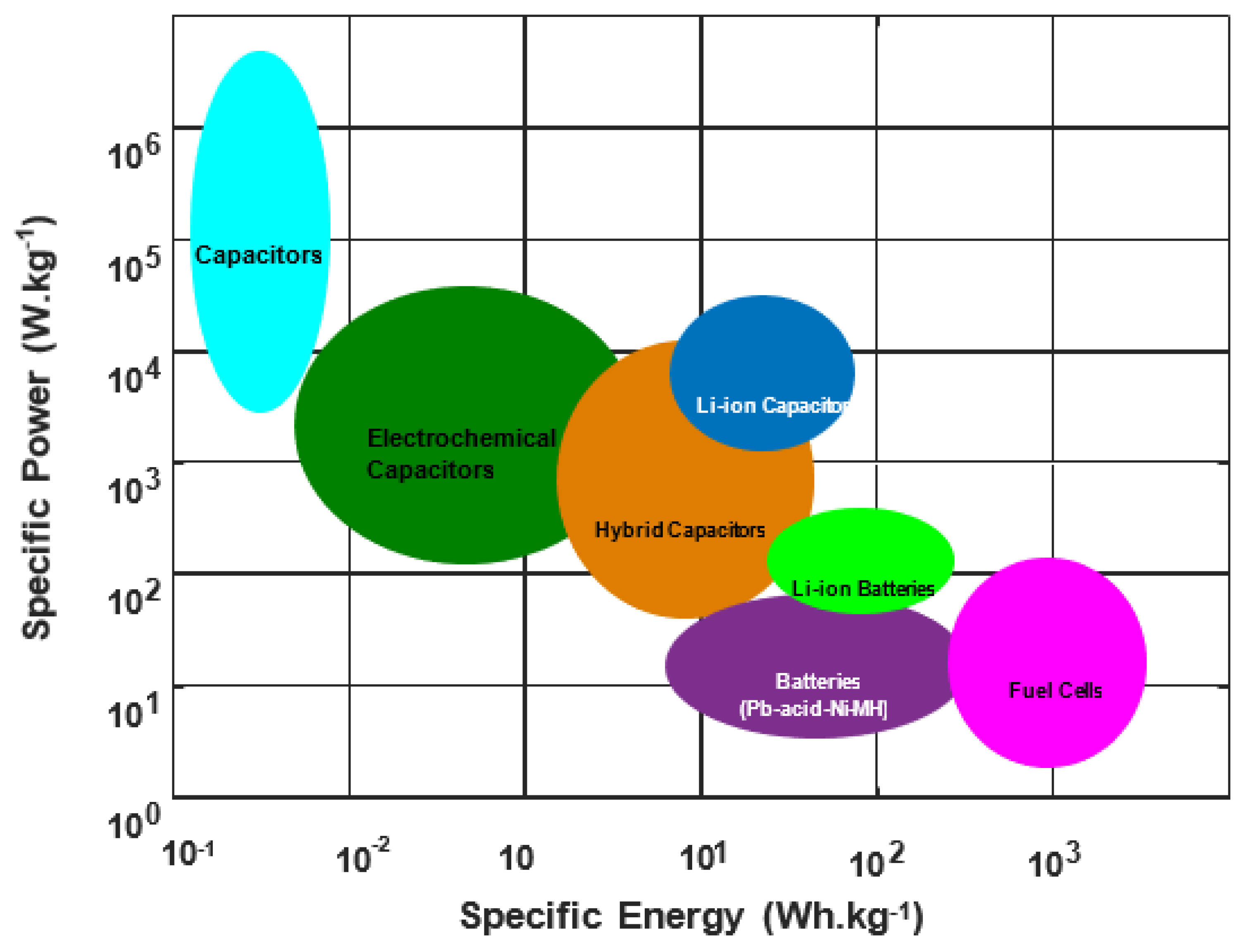
1.2. Energy Storage Density

By definition, a key component in the capacity of dielectric capacitors to store energy is their capacitance (C), which can be represented by the incremental quantity of charge (dQ) brought about by an external electric field (dV). Figure 2c illustrates how to compute dielectric capacitors using their specs and shape as well as their permittivity, which is determined using the following formula:
C = ε 0 ε r d A = d Q d V
where A stands for the plate area of the dielectric capacitors, ε 0 stands for the vacuum permittivity, ε r for the relative permittivity, and d stands for the thickness of the dielectrics. The voluminal energy-storage density W (=J/Vvol) is used as a normalized metric to represent the amount of stored energy per unit volume Vvol (=Ad) in a dielectric capacitor. Electrostatic energy may be stored in dielectrics during the charging process:
W = J A = 0 Q m a x V d q A d = 0 D m a x E d D      
where E is the applied electric field (=V/d), Qmax is the highest charge that was achieved under the maximum electric field (Emax) at the end of the charging process, and D is the electrical displacement that is comparable to the charge areal density (Q/A) of dielectrics. The relational equation D = ε 0 ε r E = P + ε 0 E demonstrates that the Formula (3) may be rewritten as integral over its polarization (P):
W = 0 P max E d P    
In the presence of the greatest electric field, Pmax is the maximum degree of polarization. Because it makes it straightforward to check these two electrical experiment parameters, P and E, formula (3) is well known and used to evaluate the efficacy of energy-storage devices. Since the electrical displacement or permittivity in linear dielectrics is unaffected by the applied electric field, the following formula may be used to estimate energy-storage density, which corresponds to the green shaded area in Figure 2c:
W = ε 0 ε r E 2
Whether the dielectrics are linear or nonlinear, it is evident that the applied electric field or permittivity has a substantial impact on the energy-storage density. Given that energy dissipation in dielectric materials is unavoidable, especially in nonlinear dielectric materials like FEs, RFEs, and AFEs, where it is represented as joule heat loss, the following deformation is advised for determining recoverable energy-storage density (Wrec):
W r e c = P r P max E d P    
where Pr stands for the residual polarization. Dielectric nonlinearity, a phenomenon in which permittivity commonly displays a nonlinear declining trend as a function of an electric field, is a characteristic of the majority of dielectric materials. Although semielectric phase insulators do produce some nonlinearity, nonlinear insulators like nonferrous and ferroelectric insulators have intrinsic properties that make them unfavorable for high-energy storage densities. These intrinsic properties include a decrease in permittivity under a given field. The increase in permittivity will enhance the capacity to store energy in a certain electric field by attaining a greater bias. Above this electric field, carrier injection will take place, leading to considerable energy loss, inadequate insulation, and dielectric nonlinearity. Therefore, a combination of high bias with electric field independence, high-breakdown resistance, and little dielectric loss is a feasible technique to produce large energy-storage densities in insulators, which will aid in reducing dielectric energy-storage devices.

1.3. State-of-the-Art in Ceramics

For more than 20 years there has been discussion on whether lead-free electro-ceramics can completely replace their lead-based counterparts. On most criteria, lead-based compositions perform better than their lead-free equivalents. In addition, there are many other formulations that would be needed to address the features of basically doped PZT in lead-free compositions. Environmental restrictions, however, are quite likely to cause lead-free electro-ceramics to begin to displace their lead-based counterparts and reach development on a massive scale in the coming years, provided that the performance, dependability, and cost of lead-free are equal to PZT [29,30,31,32]. The probability of lead-free high-energy-density capacitors entering mass production is the highest of any application due to:
(1)
The ability to compensate for a raising the BDS, by a decrease in inherent electrical characteristics, frequently by reducing layer thickness (see Section 1.4.1).
(2)
The market dominance of lead-free BT-based MLCCs, which are expected to continue to grow.
Figure 3 summarizes the different dielectric materials for different types of ceramic capacitors.

1.4. Bulk Ceramics

1.4.1. Lead-Based-Ceramics

Commercially, lead-based ceramics are employed as energy-storage components in high-power pulsed capacitors, because of their superior Wrec. More details in [29,30,31,32] provide an overview of the energy-storage capabilities of lead-based ceramics, including RFE and AFE.
  • Lead-Based-Relaxor-Ferroelectrics
It has been suggested that a variety of lead-based RFEs, including Pb(Mg1/3Nb2/3)O3-PbTiO3 (PMN-PT), Pb(Zn1/3Nb2/3)O3-PbTiO3 (PZN-PT), and (Sr,Pb,Bi)-TiO3 (SPBT)-based materials, might be used to make energy-storage capacitors [33,34,35,36,37,38,39,40,41]. In the investigation of the relaxation behavior and energy-storage capabilities of the ceramic (1-x)PMN-xPT, [34] it was discovered that Wrec = 0.47 J cm−3 at ambient temperature. The findings in [42] demonstrate how the domain structure of 0.2PMN-0.8Pb(SnxTi1-x)O3 (PMN-PSxT1-x) ceramics affected Wrec and thermal stability. The 0.2PMN-0.8PST ceramics showed Wrec = 0.85 J cm−3 with outstanding thermal robustness due to the existence of ferroelectric material and PNRs.
  • Lead-Based-Antiferroelectrics
The earliest known AFE is PbZrO3 (PZ), which displays a double P-E hysteresis loop beneath TC. However, the applications for energy storage are limited by the large critical switching field needed for an AFE-FE phase transition at room temperature. A successful solution to the issue is chemical substitution, and several well-known PbZrO3-based compositions are evaluated: (Pb,La)(Zr,Ti)O3 (PLZT) [43,44,45,46], (Pb,La)(Zr,Sn,Ti)-O3 (PLZST) [47,48,49,50,51,52,53,54,55,56,57,58,59], and (Pb,La)(Zr,Sn)O3 [60,61] are three examples of this compound (PLZS). On the basis of PbHfO3, Pb(Lu0.5Nb0.5)O3, Pb(Yb0.5Nb0.5)O3, and Pb-(Tm0.5Nb0.5)O3, several novel AFEs have also been discovered [62,63].
  • (Pb,La)(Zr,Sn,Ti)O3(PLZST)
Sn might be replaced on the PLZT B-site, in accordance with the phase transition from 1989, to increase the chemical variety of AFE and the capacity of PLZT ceramics for energy storage [64].
  • (Pb,La)(Zr,Ti)O3 (PLZT)
The PLZT is present in the PbZrO3-PbTiO3 solid solution as homogenous compositions throughout a broad range of mol % La [64,65].
  • (Pb,La)(Zr,Sn)O3 (PLZS)
An unusual E-induced multistage transition in PLZS is said to occur when a conventional AFE-FE phase transition at low E is followed by a second FE phase transition at a higher E, increasing polarization, according to the authors of article [30]. Additionally, 400 kV cm−1 produced 131 Wrec of 10.4 J cm−3 and dielectric loss of 87% for (Pb0.98La0.02)-(Zr0.55Sn0.45)0.995O3 ceramics, as well as an improved discharge current density of 1640 A.m−2 and an ultrafast discharge speed (75 ns discharge time).

1.4.2. Lead-Free-Ceramics

Over the past few decades, a lot of research has focused on lead-free electro-ceramics due to worries about the toxicity of lead and lead oxide-based compounds [66,67,68]. The performance of their energy storage has been slowly but steadily improved, replacing the old lead-based materials. For energy-storage applications, a variety of lead-free ceramic systems, including those based on BT, ST, KNN, BF, NBT, AgNbO3 (AN), and NN, are being researched as prospective alternatives for PLZT.
  • BaTiO3-Based-Ceramics
Since they were first developed, BT-based dielectric ceramics have dominated the ceramic capacitor industry [69,70].
  • SrTiO3-Based-Ceramics
ST is a potential applicant for energy-storage applications, an emerging ferroelectric, due to its relatively high permittivity (εr~300) and low dielectric loss (1% at ambient temperature).
  • K0.5Na0.5NbO3-Based-Ceramics
When the energy-storage capabilities of KNN-(Bi,Na)HfO3 solid solutions were initially studied in 2016, Wrec of ~ 0.54 J cm−3 was attained at 129 kV cm−1.
  • BiFeO3-Based-Ceramics
Due to its high TC and considerable change requires, BF-based ceramics, best known as multiferroics, have been explored for high temperature ferroelectric and piezoelectric purposes [71,72,73,74].
  • Na0.5Bi0.5TiO3-Based-Ceramics
Due to their high Pmax and Tc, NBT-based ceramics are interesting options for lead-free dielectrics.
  • AgNbO3-Based-Ceramics
AFEs have long been recognized as the ideal material for energy-storage capacitors due to their high Pmax and low Pr. The fact that AN has a high-saturation polarization of 52 C cm−2 under an E max of 220 kV cm−1 makes it stand out among the few lead-free AFE systems.
  • NaNbO3-Based-Ceramics
AFE NN has recently drawn interest as a possible contender for energy-storage applications. Due to the tiny bandgap energy between both the AFE phase and the field-induced FE phase and the metastability of the E-induced FE phase, it is challenging to detect an AFE double hysteresis loop in NN.

1.5. Glass Ceramics

One or more uniformly dispersed crystalline phases (ceram-ics) in an amorphous phase are what make up glass-ceramics (glass). Based on the formed crystalline forms and their micro-structural features, they typically display the combination qualities of ceramics and glass. To manufacture glass-ceramics, the essential raw materials are first melted, then allowed to cool to room temperature to form a glass. Finally, the glass-ceramics are twice annealed to promote crystal nucleation and growth above the glass transition temperature (Tg).

1.6. Ceramic Multilayers

As illustrated in [75,76,77], a variety of processing stages are used to create ceramic MLs. These procedures include slurry preparation, tape-casting, screen printing, laminating, co-sintering, and termination. This manufacturing method, which is based on powder, allows for the scaling-up of laboratory research to industrial manufacturing. The market for ceramic MLs, which are used in electronic applications, including as mobile phones, computers, and automobiles, was $5.3 billion in 2017 but is estimated to grow to $7.8 billion by 2024. Figure 4 summarizes the energy-storage characteristics for several ceramic MLs.
Figure 5a,b show the temperature [78] and frequency-dependence [79] Wrec for some reported electro-ceramic materials used in high-energy-density capacitors. Advanced high-energy-density ceramic MLs are being created to support power electronics in hybrid electric vehicles which demand greater Wrec and operating temperatures. These materials are based on AFEs and RFEs. In order to develop the most effective ceramics, research into low-cost internal electrodes is also necessary.

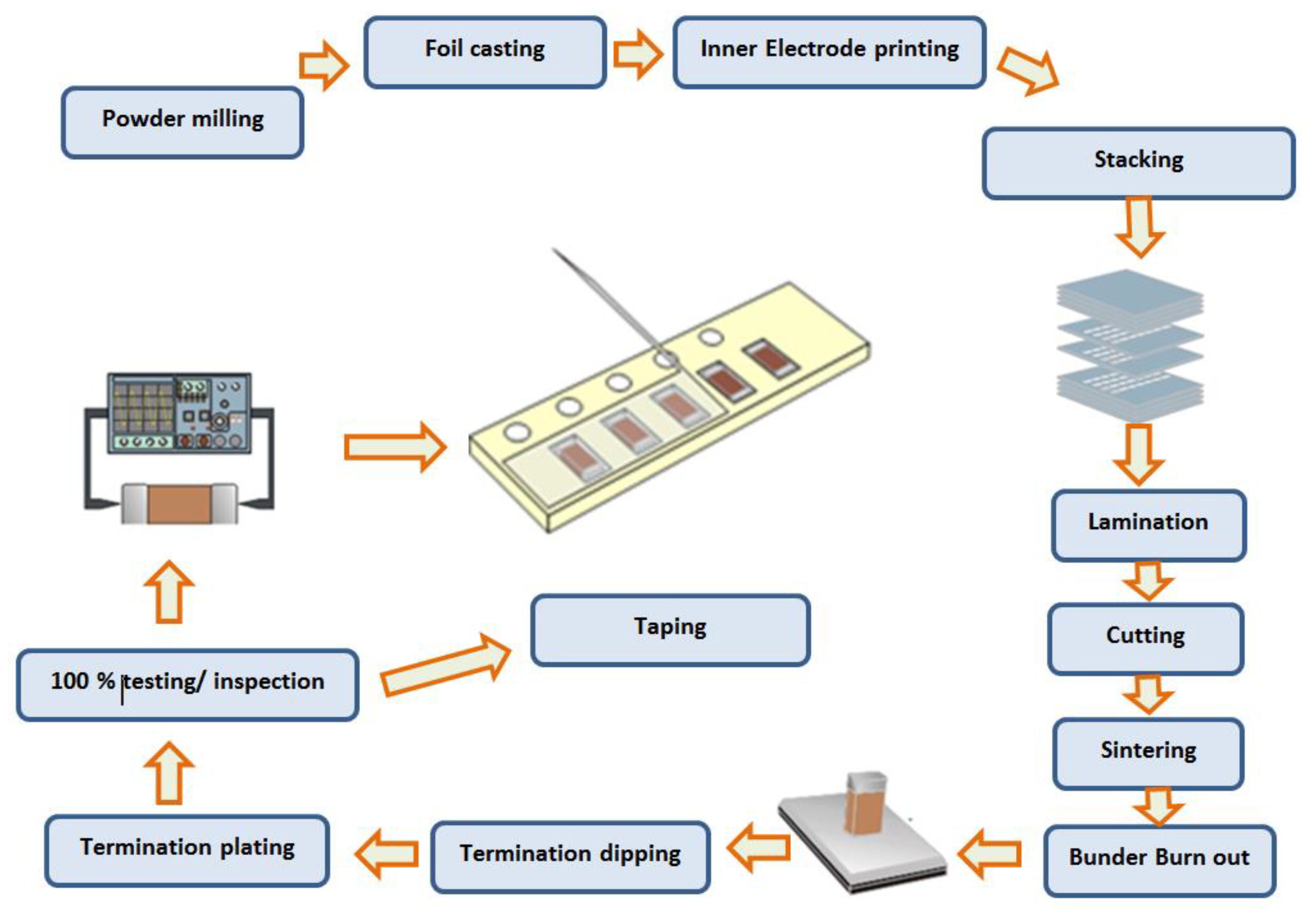
2. MLCC and Its Fabrication Process

The exact structure and manufacturing procedure of the MLCCs are shown schematically in Figure 6. MLCCs are constructed by alternately layering numerous dielectric layers in tandem with inner electrodes. The inner electrodes are connected to the outside terminal for surface installation. In place of expensive Pd, base metals like Ni and Fe are increasingly used as inner electrode materials. The exterior termination is constructed of layers of Cu or Ag, Ni plating, and Sn plating. It is possible to express the MLCC capacitance as in Equation (1). When choosing the chip size and dielectric materials, the thickness of the dielectric layer and the number of stacked layers are important design considerations for MLCCs with high capacitance [92].
This process is commonly used to create MLCCs. Firstly, the balling procedure is used to homogeneously blend fine ceramic powders used for dielectric layers with a binder, solvents, and additives like dopants and sintering aids. To improve the dependability and performance of MLCCs, the composition of the starting materials is strictly controlled. The slurry-like shapes of the combinations make them easy to handle and process. Using the tape-casting method, the slurry is cast into a thin, continuous film. After drying and being cut into equal-sized sheets, the green sheets are then screen printed with metal paste. The required number of green sheets are stacked using inner electrodes, and the stack is subsequently compressed to produce a laminate by applying pressure [93]. The laminated sheets are cut into appropriate bits for chips. For stacking and cutting, extremely high mechanical and alignment precision is required. After cutting, the chips’ binder is burned away, and the chips are then sintered. Since the chips have a multi-layered structure of dielectric layers and inner electrodes, controlling the sintering temperature and the environment is essential to preventing shrinkage and failures during the sintering process. To connect the internal electrodes in parallel on the chip, termination is made using the tumbling, dipping, and firing operations. The manufacture of MLCC chips is finished after electrical testing to ensure quality. The manufacture of high-capacitance MLCCs is fraught with problems. Fine raw powders (o300 nm) are needed for thinner and smoother inner electrode layers and dielectric layers. As a result, there has been a lot of study into the manufacturing of tiny particles for the metal inner electrode and the dielectric layer [94]. Functional ceramic devices have reduced in size and become thinner, more refined, and more integrated in recent years, making it challenging to implement their fast prototyping and low-cost manufacture using conventional techniques. Multi-material 3D printing is an emerging technology that offers greater complexity and more creative freedom in the design of functional ceramic devices due to its singular capacity to instantly create 3D parts that incorporate various material constituents without the need for a time-consuming procedure or expensive tools [102,103,104,105]. However, strip lines, micro-strip lines, and vias are typically present in functional ceramic devices with composite structures that are made of two or more materials. In addition to improving the spatial resolution and printing speed, numerous issues relating to the raw materials, printing strategies, and sintering process still need to be resolved. Functional ceramic devices are now being developed via multi-material 3D printing, which has considerable research motivation and application promise [106,107]. Some popular 3D printing processes are shown in Figure 7.
Conventional MLCCs based on BaTiO3 have been fabricated with noble metals such as platinum (Pt) or palladium (Pd) as internal electrodes which can be fired with dielectrics in air at 1300 °C or higher. With an increased number of stacked layers due to miniaturization and higher capacitance of MLCCs, the proportion of the electrode cost to the overall cost increases steeply. Thus, a cost reduction of the internal electrodes has been intensively investigated for reducing the cost of MLCCs [108]. Methods for reducing the internal electrode cost are classified into:
(1)
The use of silver (Ag)/Pd alloy electrodes having a high Ag content (more than 70%) to achieve low temperature sintering of the dielectrics.
(2)
The use of base metals such as nickel (Ni) and copper (Cu) as internal electrodes by using a nonreducible dielectric that can be fired in a reducing atmosphere [109].
Table 2 shows the physical properties and price ratio of various electrode materials for MLCCs.
The performance, dependability, and functionality of the electrode materials used in MLCCs are negatively impacted by residual stress, mechanical cracking from sintering shrinkage, and metal diffusion into the dielectric layer, all of which are caused by high sintering temperatures for dielectric materials. In order to avoid the oxidation of the base metal inner electrode, the green chips are additionally co-fired at low oxygen pressure. During sintering in a reducing environment, dielectric layers can experience a significant compositional change and defect development. The sintering environment must be meticulously regulated to minimize decrease of the dielectric material and to limit oxidation of the inner electrodes [33,95].

3. Reliability

In actuality, temperature, frequency, voltage fluctuation, and many other factors that affect the cyclic charge and discharge process are related with dielectric capacitors and their integrated systems as well as the operating circumstances. Therefore, strong fatigue resistance, often known as outstanding dependability, ensures the physical integrity of pulsed systems made up of dielectric capacitors, enabling energy-storage performance under demanding situations. By studying the characteristics of polarization hysteresis loops under particular conditions, one may gauge the capacity to withstand shocks [78]. Dielectric capacitors are a common illustration of a device that has a crucial need for thermal stability of energy-storage performance at high temperatures. Due to its thermo-decomposition temperature being below 105 °C, the best commercially available polymer, BOPP, must be used in power inverters of hybrid and electric vehicles with secondary cooling systems. This has constraints on the quantity of accessible space, adds weight and volume, raises production costs, and wastes energy [95]. From this point on, ultra-high dependability with little to no instability or fluctuation is urgently required for energy-storage dielectrics in pulse circuits under demanding conditions.

4. MLCCs Failure Mechanisms, Testing Strategies and Fault Diagnosis

The most frequent cause of failure is a short circuit caused by the spread of ceramic cracks that start at the end caps of the device. MLCC failures frequently start during PCB manufacturing due to mechanical stress brought on by the equipment used for PCB assembly, or thermal stress brought on by the soldering process, which can be compounded by using the wrong solder fillet profile. The placement of MLCCs on a PCB might affect their dependability because those parts that are close to the edge of the board may experience excessive mechanical stress during PCB de-paneling. Figure 8 presents the most common reasons for MLCC failures.
Therefore, it is important to ensure that there is no excessive mechanical stress caused by the de-paneling procedure, the component mounting, or PCB mounting method. The same holds true for various connections and PCB components. These parts will have a decreased likelihood of failing due to cracking since MLCCs for automotive and aerospace applications are built with softer resin material in the capacitor end caps, which lessens the mechanical stresses on the actual ceramic device region. The functioning of these pieces is shown in Figure 9a,b, which also show how employing them will reduce the likelihood of fractures forming during manufacture and the susceptibility of the devices to temperature cycling and ambient vibration when in operation [28]. In the wake of environmental stress testing, MLCCs are frequently checked for cracking. The capacitors are often subjected to micro-sectioning to identify any fractures. However, this analytical method by itself has the potential to cause device fractures [79,99]. High-resolution CT X-ray component analysis can offer a more accurate evaluation of cracking in MLCCs, albeit a slower and possibly more expensive procedure. When used, MLCCs are frequently subjected to a constant DC bias, which can induce electrochemical migration and, in cases where silver is present in the component interconnects, a short circuit failure mode. The introduction of COTS components that are ROHS compliant increases the chance of silver being present within these space applications. Operation in an environment with high humidity will amplify this impact. Utilizing PCBs with conformal coatings may help to reduce the impact, but this is not a guarantee. Additionally, electro migration may take place below the components, accelerated by the presence of trapped flux residues, in which case visual inspection of the components (for example, as part of high temperature and humidity stress testing) will not be able to find the fault [28,100].
There are several different analytical methods that may be used to evaluate capacitors. The following section discusses some of the most helpful strategies, along with their respective benefits and limitations. The primary analytical methods utilized in failure investigation and component screening are sectioning and CT X-ray imaging because cracking is the most frequent MLCC failure mechanism. Sectioning must be performed carefully since the operation itself can cause cracks to emerge in the sample. Consequently, the capacitor should be removed from the circuit and printed on a wiring board using a high-speed diamond saw, allowing a reasonable space between the cut and the component. The portion should then be installed and potted using a material that will not subject the component to stress [79,99]. A fine grade of abrasive should be used for grinding to the desired plane. The gadget should be used to analyze many successive planes, paying close attention to the beginning of fractures from the inner edge of the solder fillet. MLCCs may be checked for cracks using CT X-ray imaging. This method has the benefit of being nondestructive, but it also has the drawback of being a sluggish method (although probably faster than sectioning). It is also conceivable that extremely small/fine cracks are overlooked since there is a limit to the size of feature that can be resolved. When it comes to finding fractures in thick materials like ceramic capacitors, scanning acoustic microscopy (SAM) is quite successful. Unfortunately, the procedure is useless since fractures are likely to appear below the capacitor end caps. High-frequency transducers (e.g., >100 MHz) are needed to image materials at a high resolution; however, at these frequencies, sound energy is easily dispersed and attenuated, making it challenging to quantify any characteristics beneath the end cap metal acoustically. Table 3 summarizes the MLCCs failure mechanisms with their specific performances. The paint has conductivity flaws, air bubbles, poor paint density, and incomplete drying of the coating encapsulation layer.

4.1. Humidity’s Impact on Electrical Characteristics’ Degradation

When the air humidity is too high, a water film condenses on the surface of the capacitor shell, reducing the surface insulation resistance of the capacitor. In semi-sealed capacitors, moisture can also penetrate the capacitor medium, lowering its insulation resistance and insulation power. As a result, a high-temperature, high-humidity environment has a significant negative influence on the characteristics of capacitors. After drying and dehumidifying, capacitors’ electrical characteristics can be improved, but the effects of water molecule electrolysis cannot be completely eradicated [99,110].

4.2. Consequences of Silver Ion Migration

Most inorganic dielectric capacitors use silver electrodes as their primary material. Water molecules that infiltrate semi-sealed capacitors that are heated up result in electrolysis since they are permeable. When silver ions combine with hydroxide ions to form silver hydroxide in the anode, a process called oxidation occurs. When silver hydroxide interacts with hydrogen ions in the cathode—a reaction called a reduction—silver and water are produced. Discontinuous metallic silver particles are produced by repeatedly decreasing the silver ions in the anode to the cathode through the electrode reaction. These particles stretch toward the anode in a tree-like arrangement, connected by the water layer. The leakage current is increased by the migration of silver ions into the interior of the inorganic medium as well as on its surface. In severe cases, a full short circuit between the two silver electrodes might occur, which will destroy the capacitor [79].
In conclusion, silver ion migration can deteriorate the electrical characteristics of open inorganic dielectric capacitors as well as possibly causing a decrease in the dielectric breakdown field strength, which will cause the capacitor to fail [97].
It is important to note that due to silver ion migration, low-frequency ceramic monolithic capacitors with silver electrodes fail far more frequently than other varieties of ceramic dielectric capacitors. The channel is condensed as the silver ions move, which frequently results in short circuits.

4.3. Ceramic Capacitors’ Mechanism of Failure in High-Temperature Environments

When semi-sealed ceramic capacitors are utilized in high-humidity settings, breakdown failure is a regular and significant issue. Surface arcing breakdown and dielectric breakdown are the two forms of breakdowns that might happen. A dielectric breakdown can be categorized as either an early breakdown or an old breakdown depending on when it occurs. Capacitor dielectric material defects are revealed through early failure and manufacturing processes. These flaws drastically lower the dielectric strength of ceramic dielectrics. The capacitor will have an electrical failure either in the resist total power or in the initial phases of operation due to the influence of the electric field in a high-humidity environment. The electrochemical disintegration of cells is the most typical kind of aging. Electrolytic age breakdown has become a highly prevalent problem as a result of the migration of silver in ceramic capacitors. Due to the formation of conductive dendrites caused by silver migration, which can increase local leakage current, the capacitor may burn out or rupture due to thermal failure [78]. The most common geometries for thermal breakdown to occur in are tubular or disc-shaped small ceramic dielectric capacitors because local heating is intense during the breakdown and, additionally, thinner tube walls or smaller ceramic bodies are more likely to burn or shatter. When the titanium dioxide reduction process takes place in a ceramic medium made primarily of titanium dioxide, the titanium ion may also change under stress from tetravalent to trivalent. With time, the capacitor’s dielectric strength significantly decreases, which could result in capacitor failure. Therefore, compared to ceramic dielectric capacitors without titanium dioxide, these ceramic capacitors experience more severe electrolytic breakdown [99].

4.4. Improvement of Electrode Materials

Ceramic capacitors have historically used silver electrodes. Silver ion migration and the subsequent fast aging of ceramic dielectrics containing titanium are the primary reasons for ceramic capacitor failure. Some manufacturers have utilized nickel electrodes rather than silver electrodes for making ceramic capacitors, using electroless nickel to plate the ceramic substrate. Because nickel is both chemically more stable than silver and electrically less mobile than silver, ceramic capacitor performance and reliability are boosted [28,78]. Due to the extensive use of the silver electrode and the ceramic material being sintered at 900 °C, the monolithic low-frequency ceramic dielectric capacitor (with silver as the electrode) has a significant amount of porosity, which prevents the ceramic material from achieving a dense ceramic medium. Depending on the cosolvent barium oxide’s excellent penetration or “mutual fusion” capability with silver at high temperatures, this will result in a macroscopically visible “porcelain absorption of silver” occurrence.

4.5. Fracture of Laminated Ceramic Capacitors

The brittleness of the dielectric determines the most frequent failure mechanism for laminated ceramic capacitors, which is fracture. The laminated ceramic capacitor, which is directly fused to the circuit board, could be unable to absorb the mechanical stress. The leaded ceramic capacitor might be able to do so through the pins. As a result, the principal cause of laminated ceramic capacitor rupture will be mechanical stress brought on by varied thermal expansion coefficients or circuit board bending [28].

4.6. Analysis of Laminated Ceramic Capacitors’ Fractures

Once the laminated ceramic capacitor has been mechanically fractured, there will be an arc discharge between two or more electrodes and a total failure of the laminated ceramic capacitor because the electrode insulation separation at the fracture will be lower than the breakdown voltage. Reducing mechanical stress is the primary method of protecting laminated ceramic capacitors from mechanical fracture. This can be accomplished by minimizing the circuit board’s bending, reducing the strain placed on the board by the ceramic chip capacitor, and reducing the difference in thermal expansion coefficient between the laminated ceramic capacitor and the circuit board [22,28].
By selecting a capacitor with a small package size, users may lessen the mechanical stress brought on by the discrepancy in the thermal expansion coefficient between the laminated ceramic capacitor and the circuit board. For the aluminum circuit board, for instance, the smallest box should be utilized. The issue can be resolved with multiple parallel connections, lamination, ceramic capacitors in pin packages, or any combination of these.

4.7. Melted of the Electrode Terminals of the Laminated Ceramic Capacitor

When wave soldering laminated ceramic capacitors, the electrode terminals may melt off. The main factor here is the extremely prolonged contact between the laminated ceramic capacitors used in wave soldering and the high-temperature solder. There are now two types of laminated ceramic capacitors available: those that can be wave soldered and those that can be reflow soldered, the intensely nauseating occurrence [13,22,111]. The appropriate precautions for laminated ceramic capacitors go into depth on the temporal characteristics of high-temperature solder that the electrode terminals of laminated ceramic capacitors may withstand under different welding techniques. The answer is straightforward: either use laminated ceramic capacitors that conform to the wave soldering technique as much as is practical while employing it or use wave soldering as little as possible.

5. Conclusions and Outlook

Dielectric capacitors with a ceramic base are crucial energy-storage components in modern electronic and electrical power systems. Ceramic-based dielectrics have been demonstrated to be the most promising choices for energy-storage applications, as shown throughout this study and summarized in Figure 4. Despite the advances made in terms of creating material systems and structures, further research on improving overall energy storage performance has to be conducted so as to address the following issues:
(1)
The capacity to improve. To identify how to effectively control material and device fabrication conditions when scaled up, basic research must be undertaken. It must also be determined whether the cost gradients and the fine-tuning method used in small-scale energy storage MLCCs can be scaled up for production.
(2)
Compatibility with the electrode made of base metal. The internal electrode of contemporary, high-energy-density MLCCs is made of precious metals, however base metals must be used in their stead to significantly cut costs. The dielectric material must be anti-reducing or low burn in order to be compatible with base metal electrodes. Additionally, other concerns like high temperature, high frequency, and strong electric field must be addressed in order to retain high-energy storage performance under harsh circumstances.
(3)
Great reliability. MLCCs long-term suitability for high-quality industrial applications is determined by their great dependability. It is necessary to solve the performance decline and failure caused by the plurality of electrical, thermal, mechanical, and wet physics. Effective theories, models, approaches, experimental platforms, and simulation methodologies of rapid deterioration are needed for this.
(4)
Application-specific assessment and measurement. For the particular applications indicated above, the way energy-storage performance is currently measured and assessed differs from actual usage. As a result, the produced materials and gadgets cannot presently be used in actual applications. On the basis of collaboration between researchers and producers, appropriate standards should be set. Despite these difficulties, it is anticipated that high-energy-density MLCCs will eventually be produced because of their utility in intensive research and development.
(5)
By taking into account all the factors that might affect the state of operation or the state of health, these proposals give a great contribution to the evolution of the state of the MLCCs. However, certain methods cannot be used because of the limitations of technological circumstances. For instance, the excessively high breakdown voltage prevents in-site electron microscopy from directly seeing the dynamic destruction of microstructure.
Until now, MLCCs have been used in a wide range of products, including electric vehicles, personal computers, mobile phones, and televisions. Furthermore, their scope of use has expanded significantly in light of the development of the Internet of Things (IoT). From the perspective of designing dielectric materials, the present challenges and recent advancements in creating MLCCs with high capacitance and reliability are outlined in Figure 10. By taking into account all the factors that might affect the state of operation or the state of health (frequency, voltage stability, temperature, etc.), the ideas in this study provide a significant contribution to the development of the state of the MLCCs for future work.
Future research will concentrate on using comparable circuit strength and order in relatively basic models. The constraints of this approach, however, are that it cannot demonstrate the kinetics of internal reactions, nor the capacitor’s deterioration and the aging course of the MLCCs. Hence, a fused system would offer great predictive efficiency in assessing how various factors, such as unknown aging, operating settings, and circumstances can affect MLCCs materials. The fused system combines various types of capacitor models and techniques along with an effective fusion rule, which is based on using the ESR and ESL of MLCCs as the most crucial characteristic metrics for both evaluating and extending the performance and longevity of MLCCs.

Author Contributions

Conceptualization, K.L. and A.J.M.C.; Methodology, K.L. and A.J.M.C.; Software, K.L. and A.J.M.C.; Validation, K.L. and A.J.M.C.; Formal analysis, K.L. and A.J.M.C.; Investigation, K.L.; Resources, A.J.M.C.; Writing—original draft, K.L.; Writing—review & editing, A.J.M.C.; Visualization, K.L. and A.J.M.C.; Supervision, A.J.M.C.; Project administration, A.J.M.C.; Funding acquisition, A.J.M.C. All authors have read and agreed to the published version of the manuscript.

Funding

This work was supported by the Portuguese Foundation for Science and Technology (FCT) under Projects UIDB/04131/2020 and UIDP/04131/2020.

Data Availability Statement

Not applicable.

Conflicts of Interest

The authors declare no conflict of interest.

Abbreviations

The following abbreviation have been used in the paper:
MLCCsMultilayer Ceramic Capacitors
SAMScanning Acoustic Microscopy
ROHSRestriction of the use of certain Hazardous Substances
COTSCommercial Off-The-Shelf
WrecRecoverable Energy Storage Density
AFEsAntiferroelectrics
RFEsRelaxor-ferroelectrics
FEsFerroelectrics
PrRemnant polarization
BDSBreak-Down Strength
PNRPolar Nanoregions
ESREquivalent Series Resistance
ESLEquivalent Series Inductance
BDSBreakdown Strength
PMNPb(Mg1/3Nb2/3)O3
NNNaNbO3
STSrTiO3
CTCaTiO3
ANAgNbO3
BTBaTiO3
KNN(Na, K)NbO3
BFBiFeO3
NBT(Na, Bi)TiO3
PLZT(Pb, La)(Zr, Ti)O3
PZT(Pb)(Zr, Ti)O3
PLZS(Pb,La)(Zr,Sn)O3
SBT(Sr0.7Bi0.2)TiO3
BMNBi(Mg2/3Nb1/3)O3
BMHBi(Mg0.5Hf0.5) O3
BLNBi(Li1/2Nb1/2)O3
NBTNa0.5Bi0.5TiO3
BFBiFeO3
BTBaTiO3

References

  1. Cardoso, A.J.M. Diagnosis and Fault Tolerance of Electrical Machines and Power Electronics; 2018; p. 376. ISBN 13: 978-1-78561-531-1. Available online: https://www.researchgate.net/publication/328676133_Diagnosis_and_Fault_Tolerance_of_Electrical_Machines_Power_Electronics_and_Drives (accessed on 1 February 2023).
  2. Yuan, Q.; Chen, M.; Zhan, S.; Li, Y.; Lin, Y.; Yang, H. Ceramic-Based Dielectrics for Electrostatic Energy Storage Applications: Fundamental Aspects, Recent Progress, and Remaining Challenges. Chem. Eng. J. 2022, 446, 136315. [Google Scholar] [CrossRef]
  3. Covaci, C.; Gontean, A. “Singing” Multilayer Ceramic Capacitors and Mitigation Methods—A Review. Sensors 2022, 22, 3869. [Google Scholar] [CrossRef]
  4. Pan, M.-J.; Randall, C.A. A brief introduction to ceramic capacitors. IEEE Electr. Insul. Mag. 2010, 26, 44–50. [Google Scholar] [CrossRef]
  5. Pithan, C.; Hennings, D.; Waser, R. Progress in the synthesis of nanocrystalline BaTiO3 powders for MLCC. Int. J. Appl. Ceram. Technol. 2005, 2, 1–14. [Google Scholar] [CrossRef]
  6. Ho, J.; Jow, T.R.; Boggs, S. Historical introduction to capacitor technology. IEEE Electr. Insul. Mag. 2010, 26, 20–25. [Google Scholar] [CrossRef] [Green Version]
  7. Kropp, J.; Bakran, M.-M. In-circuit-characterization of ceramic capacitor with anti-ferroelectric material for voltage source inverters. In Proceedings of the PCIM Europe 2016, International Exhibition and Conference for Power Electronics, Intelligent Motion, Renewable Energy and Energy Management, Nuremberg, Germany, 10–12 May 2016; pp. 1–8. [Google Scholar]
  8. Neumayr, D.; Bortis, D.; Kolar, J.W.; Koini, M.; Konrad, J. Comprehensive large-signal performance analysis of ceramic capacitors for power pulsation buffers. In Proceedings of the 2016 IEEE 17th Workshop on Control and Modeling for Power Electronics (COMPEL), Trondheim, Norway, 27–30 June 2016; pp. 1–8. [Google Scholar]
  9. Hao, H.; Liu, M.; Liu, H.; Zhang, S.; Shu, X.; Wang, T.; Yao, Z.; Cao, M. Design, fabrication and dielectric properties in core–double shell BaTiO3-based ceramics for MLCC application. RSC Adv. 2015, 5, 8868–8876. [Google Scholar] [CrossRef]
  10. Zhang, Y.; Wang, X.; Kim, J.; Tian, Z.; Fang, J.; Hur, K.H.; Li, L. High performance BaTiO3-based BME-MLCC nanopowder prepared by aqueous chemical coating method. J. Am. Ceram. Soc. 2012, 95, 1628–1633. [Google Scholar] [CrossRef]
  11. Kishi, H.; Mizuno, Y.; Chazono, H. Base-metal electrode-multilayer ceramic capacitors: Past, present and future perspectives. Jpn. J. Appl. Phys. 2003, 42, 1. [Google Scholar] [CrossRef]
  12. Dai, K.; Wang, X.; Niu, S.; Yi, F.; Yin, Y.; Chen, L.; Zhang, Y.; You, Z. Simulation and structure optimization of triboelectric nanogenerators considering the effects of parasitic capacitance. Nano Res. 2017, 10, 157–171. [Google Scholar] [CrossRef]
  13. Archangelo, K.C.; Guilardi, L.F.; Campanelli, D.; Valandro, L.F.; Borges, A.L.S. Fatigue failure load and finite element analysis of multilayer ceramic restorations. Dent. Mater. 2019, 35, 64–73. [Google Scholar] [CrossRef]
  14. Nagayoshi, M.; Matsubara, K.; Fujikawa, N. Analyses of microstructure at degraded local area in Ni-multilayer ceramic capacitors under highly accelerated life test. Jpn. J. Appl. Phys. 2020, 59, SPPC01. [Google Scholar] [CrossRef]
  15. Kalaiselvan, C.; Rao, L.B. Accelerated life testing of nano ceramic capacitors and capacitor test boards using non-parametric method. Measurement 2016, 88, 58–65. [Google Scholar] [CrossRef]
  16. Lall, P.; Dornala, K.; Suhling, J.; Deep, J.; Lowe, R. Effect of Dielectric Material on the Reliability of 3640 MLCC Capacitors under High-G Shock Loads. In Proceedings of the 2019 18th IEEE Intersociety Conference on Thermal and Thermomechanical Phenomena in Electronic Systems (ITherm), Las Vegas, NV, USA, 28–31 May 2019; pp. 1037–1046. [Google Scholar]
  17. Lall, P.; Dornala, K.; Deep, J.; Lowe, R. Measurement and Prediction of Interface Crack Growth at the PCB-Epoxy Interfaces Under High-G Mechanical Shock. In Proceedings of the 2018 17th IEEE Intersociety Conference on Thermal and Thermomechanical Phenomena in Electronic Systems (ITherm), San Diego, CA, USA, 29 May–1 June 2018; pp. 1097–1105. [Google Scholar]
  18. Lall, P.; Dornala, K.; Lowe, R.; Foley, J. Survivability assessment of electronics subjected to mechanical shocks up to 25,000 g. In Proceedings of the 2016 15th IEEE Intersociety Conference on Thermal and Thermomechanical Phenomena in Electronic Systems (ITherm), Las Vegas, NV, USA, 31 May–3 June 2016; pp. 507–518. [Google Scholar]
  19. Lall, P.; Patel, K.; Lowe, R.; Strickland, M.; Blanche, J.; Geist, D.; Montgomery, R. Modeling and reliability characterization of area-array electronics subjected to high-g mechanical shock up to 50,000 g. In Proceedings of the 2012 IEEE 62nd Electronic Components and Technology Conference, San Diego, CA, USA, 29 May–1 June 2012; pp. 1194–1204. [Google Scholar]
  20. Prume, K.; Waser, R.; Franken, K.; Maier, H.R. Finite-Element Analysis of Ceramic Multilayer Capacitors: Modeling and Electrical Impedance Spectroscopy for a Nondestructive Failure Test. J. Am. Ceram. Soc. 2000, 83, 1153–1159. [Google Scholar] [CrossRef]
  21. Lee, S.P.; Kang, K.W. Analysis for deformation behavior of multilayer ceramic capacitor based on multiscale homogenization approach. J. Mech. Sci. Technol. 2018, 32, 2577–2585. [Google Scholar] [CrossRef]
  22. Xuhui, Z.; Kuahai, Y.; Hongyu, X.; Bin, L.; Xingguo, K. Failure analysis of multilayer ceramic capacitor structure under high G impact load. Electron. Compon. Mater. 2016, 35, 28–31. [Google Scholar]
  23. Collins, J.; Gourdin, G.; Foster, M.; Qu, D. Carbon surface functionalities and SEI formation during Li intercalation. Carbon N. Y. 2015, 92, 193–244. [Google Scholar] [CrossRef]
  24. Yao, Z.; Song, Z.; Hao, H.; Yu, Z.; Cao, M.; Zhang, S.; Lanagan, M.T.; Liu, H. Homogeneous/inhomogeneous-structured dielectrics and their energy-storage performances. Adv. Mater. 2017, 29, 1601727. [Google Scholar] [CrossRef] [PubMed]
  25. Li, F.; Zhai, J.; Shen, B.; Zeng, H. Recent progress of ecofriendly perovskite-type dielectric ceramics for energy storage applications. J. Adv. Dielectr. 2018, 8, 1830005. [Google Scholar] [CrossRef] [Green Version]
  26. Hao, X. A review on the dielectric materials for high energy-storage application. J. Adv. Dielectr. 2013, 3, 1330001. [Google Scholar] [CrossRef]
  27. Zou, K.; Dan, Y.; Xu, H.; Zhang, Q.; Lu, Y.; Huang, H.; He, Y. Recent advances in lead-free dielectric materials for energy storage. Mater. Res. Bull. 2019, 113, 190–201. [Google Scholar] [CrossRef]
  28. Hong, K.; Lee, T.H.; Suh, J.M.; Yoon, S.-H.; Jang, H.W. Perspectives and challenges in multilayer ceramic capacitors for next generation electronics. J. Mater. Chem. C Mater. 2019, 7, 9782–9802. [Google Scholar] [CrossRef]
  29. Yuan, J.; Wang, D.-W.; Lin, H.-B.; Zhao, Q.-L.; Zhang, D.-Q.; Cao, M.-S. Effect of ZnO whisker content on sinterability and fracture behaviour of PZT peizoelectric composites. J. Alloys Compd. 2010, 504, 123–128. [Google Scholar] [CrossRef]
  30. Wang, D.; Cao, M.; Yuan, J.; Zhao, Q.L.; Li, H.B.; Zhang, D.Q.; Agathopoulos, S. Enhanced Piezoelectric and Ferroelectric Properties of Nb2O5 Modified Lead Zirconate Titanate-Based Composites. J. Am. Ceram. Soc. 2011, 94, 647–650. [Google Scholar] [CrossRef]
  31. Wang, D.; Cao, M.; Zhang, S. Piezoelectric ceramics in the PbSnO3–Pb (Mg1/3Nb2/3) O3–PbTiO3 ternary system. J. Am. Ceram. Soc. 2011, 94, 3690–3693. [Google Scholar] [CrossRef]
  32. Zhao, Q.L.; Cao, M.S.; Yuan, J.; Lu, R.; Wang, D.W.; Zhang, D.Q. Thickness effect on electrical properties of Pb (Zr0.52Ti0.48) O3 thick films embedded with ZnO nanowhiskers prepared by a hybrid sol–gel route. Mater. Lett. 2010, 64, 632–635. [Google Scholar] [CrossRef]
  33. Zhang, T.F.; Tang, X.G.; Liu, Q.X.; Jiang, Y.P.; Huang, X.X.; Zhou, Q.F. Energy-storage properties and high-temperature dielectric relaxation behaviors of relaxor ferroelectric Pb (Mg1/3Nb2/3) O3–PbTiO3 ceramics. J. Phys. D Appl. Phys. 2016, 49, 095302. [Google Scholar] [CrossRef]
  34. Liu, Z.; Lu, T.; Ye, J.; Wang, G.; Dong, X.; Withers, R.; Liu, Y. Antiferroelectrics for energy storage applications: A review. Adv. Mater. Technol. 2018, 3, 1800111. [Google Scholar] [CrossRef]
  35. Li, Y.; Sun, N.; Du, J.; Li, X.; Hao, X. Stable energy density of a PMN–PST ceramic from room temperature to its Curie point based on the synergistic effect of diversified energy. J. Mater. Chem. C Mater. 2019, 7, 7692–7699. [Google Scholar] [CrossRef]
  36. Perumal, R.N.; Athikesavan, V. Investigations on electrical and energy storage behaviour of PZN-PT, PMN-PT, PZN–PMN-PT piezoelectric solid solutions. J. Mater. Sci. Mater. Electron. 2019, 30, 902–913. [Google Scholar] [CrossRef]
  37. Li, Q.; Yao, F.-Z.; Liu, Y.; Zhang, G.; Wang, H.; Wang, Q. High-temperature dielectric materials for electrical energy storage. Annu. Rev. Mater. Res. 2018, 48, 219–243. [Google Scholar] [CrossRef]
  38. Bikyashev, E.A.; Ryush, I.O.; Reshetnikova, E.A. Structures of Pb1− xLax [Zr0.9Mg (0.1+ x)/3Nb (0.2− x)/3] O3 solid solutions, electrostriction and energy storage characteristics of a new antiferroelectric phase with disturbed translational symmetry. Ceram. Int. 2017, 43, 1429–1436. [Google Scholar] [CrossRef]
  39. Chao, M.; Liu, J.; Zeng, M.; Wang, D.; Yu, H.; Yuan, Y.; Zhang, S. High discharge efficiency of (Sr, Pb, Bi) TiO3 relaxor ceramics for energy-storage application. Appl. Phys. Lett. 2018, 112, 203903. [Google Scholar] [CrossRef]
  40. Qi, X.; Zhao, Y.; Sun, E.; Du, J.; Li, K.; Sun, Y.; Yang, B.; Zhang, R.; Cao, W. Large electrostrictive effect and high energy storage performance of Pr3+-doped PIN-PMN-PT multifunctional ceramics in the ergodic relaxor phase. J. Eur. Ceram. Soc. 2019, 39, 4060–4069. [Google Scholar] [CrossRef]
  41. Shkuratov, S.I.; Baird, J.; Antipov, V.G.; Hackenberger, W.; Luo, J.; Zhang, S.; Lynch, C.S.; Chase, J.B.; Jo, H.R.; Roberts, C.C. Complete stress-induced depolarization of relaxor ferroelectric crystals without transition through a non-polar phase. Appl. Phys. Lett. 2018, 112, 122903. [Google Scholar] [CrossRef] [Green Version]
  42. Li, Y.; Sun, N.; Li, X.; Du, J.; Chen, L.; Gao, H.; Hao, X.; Cao, M. Multiple electrical response and enhanced energy storage induced by unusual coexistent-phase structure in relaxor ferroelectric ceramics. Acta Mater. 2018, 146, 202–210. [Google Scholar] [CrossRef]
  43. Jo, H.R.; Lynch, C.S. A high energy density relaxor antiferroelectric pulsed capacitor dielectric. J. Appl. Phys. 2016, 119, 024104. [Google Scholar] [CrossRef]
  44. Gao, J.; Liu, Y.; Wang, Y.; Wang, D.; Zhong, L.; Ren, X. High temperature-stability of (Pb0.9La0.1)(Zr0.65Ti0.35) O3 ceramic for energy-storage applications at finite electric field strength. Scr. Mater. 2017, 137, 114–118. [Google Scholar] [CrossRef]
  45. Li, B.; Liu, Q.; Tang, X.; Zhang, T.; Jiang, Y.; Li, W.; Luo, J. High energy storage density and impedance response of PLZT2/95/5 antiferroelectric ceramics. Materials 2017, 10, 143. [Google Scholar] [CrossRef] [Green Version]
  46. Yan, F.; Yang, H.; Ying, L.; Wang, T. Enhanced energy storage properties of a novel lead-free ceramic with a multilayer structure. J. Mater. Chem. C Mater. 2018, 6, 7905–7912. [Google Scholar] [CrossRef]
  47. Chen, S.; Wang, X.; Yang, T.; Wang, J. Composition-dependent dielectric properties and energy storage performance of (Pb, La)(Zr, Sn, Ti) O3 antiferroelectric ceramics. J. Electroceram. 2014, 32, 307–310. [Google Scholar] [CrossRef]
  48. Zhuo, F.; Li, Q.; Li, Y.; Gao, J.; Yan, Q.; Zhang, Y.; Chu, X.; Cao, W. Effect of A-site La3+ modified on dielectric and energy storage properties in lead zironate stannate titanate ceramics. Mater. Res. Express. 2014, 1, 045501. [Google Scholar] [CrossRef]
  49. Liu, X.; Li, Y.; Sun, N.; Hao, X. High energy-storage performance of PLZS antiferroelectric multilayer ceramic capacitors. Inorg. Chem. Front. 2020, 7, 756–764. [Google Scholar] [CrossRef]
  50. Xu, R.; Xu, Z.; Feng, Y.; Wei, X.; Tian, J.; Huang, D. Evaluation of discharge energy density of antiferroelectric ceramics for pulse capacitors. Appl. Phys. Lett. 2016, 109, 032903. [Google Scholar] [CrossRef]
  51. Liu, Z.; Dong, X.; Liu, Y.; Cao, F.; Wang, G. Electric field tunable thermal stability of energy storage properties of PLZST antiferroelectric ceramics. J. Am. Ceram. Soc. 2017, 100, 2382–2386. [Google Scholar] [CrossRef]
  52. Xu, R.; Tian, J.; Zhu, Q.; Zhao, T.; Feng, Y.; Wei, X.; Xu, Z. Effects of La-induced phase transition on energy storage and discharge properties of PLZST ferroelectric/antiferroelectric ceramics. Ceram. Int. 2017, 43, 13918–13923. [Google Scholar] [CrossRef]
  53. Shen, J.; Wang, X.; Yang, T.; Wang, H.; Wei, J. High discharge energy density and fast release speed of (Pb, La)(Zr, Sn, Ti) O3 antiferroelectric ceramics for pulsed capacitors. J. Alloys Compd. 2017, 721, 191–198. [Google Scholar] [CrossRef]
  54. Zhang, Q.; Dan, Y.; Chen, J.; Lu, Y.; Yang, T.; Yao, X.; He, Y. Effects of composition and temperature on energy storage properties of (Pb, La)(Zr, Sn, Ti) O3 antiferroelectric ceramics. Ceram. Int. 2017, 43, 11428–11432. [Google Scholar] [CrossRef]
  55. Dan, Y.; Xu, H.; Zou, K.; Zhang, Q.; Lu, Y.; Chang, G.; Huang, H.; He, Y. Energy storage characteristics of (Pb, La)(Zr, Sn, Ti) O3 antiferroelectric ceramics with high Sn content. Appl. Phys. Lett. 2018, 113, 063902. [Google Scholar] [CrossRef]
  56. Dan, Y.; Xu, H.; Zhang, Y.; Zou, K.; Zhang, Q.; Lu, Y.; Chang, G.; Zhang, Q.; He, Y. High-energy density of Pb0. 97La0. 02 (Zr0.50Sn0.45Ti0.05) O3 antiferroelectric ceramics prepared by sol-gel method with low-cost dibutyltin oxide. J. Am. Ceram. Soc. 2019, 102, 1776–1783. [Google Scholar] [CrossRef] [Green Version]
  57. Lu, Z.; Wang, G.; Bao, W.; Li, J.; Li, L.; Mostaed, A.; Yang, H.; Ji, H.; Li, D.; Feteira, A.; et al. Superior energy density through tailored dopant strategies in multilayer ceramic capacitors. Energy Environ. Sci. 2020, 13, 2938–2948. [Google Scholar] [CrossRef]
  58. Yu, Y.; Zhang, Y.; Zou, K.; Chen, G.; Zhang, Y.; Li, H.; Lu, Y.; Zhang, Q.; He, Y. High energy density and efficiency in (Pb, La)(Zr, Sn, Ti) O3 antiferroelectric ceramics with high La3+ content and optimized Sn4+ content. Ceram. Int. 2019, 45, 24419–24424. [Google Scholar] [CrossRef]
  59. Zhao, Q.; Lei, H.; He, G.; Di, J.; Wang, D.; Tan, P.; Jin, H.; Cao, M. Effects of thickness on energy storage of (Pb, La)(Zr, Sn, Ti) O3 antiferroelectric films deposited on LaNiO3 electrodes. Ceram. Int. 2016, 42, 1314–1317. [Google Scholar] [CrossRef]
  60. Wang, H.; Liu, Y.; Yang, T.; Zhang, S. Ultrahigh energy-storage density in antiferroelectric ceramics with field-induced multiphase transitions. Adv. Funct. Mater. 2019, 29, 1807321. [Google Scholar] [CrossRef]
  61. Liu, X.; Li, Y.; Hao, X. Ultra-high energy-storage density and fast discharge speed of (Pb 0.98− x La 0.02 Sr x)(Zr 0.9 Sn 0.1) 0.995 O3 antiferroelectric ceramics prepared via the tape-casting method. J. Mater. Chem. A Mater. 2019, 7, 11858–11866. [Google Scholar] [CrossRef]
  62. Yang, X.; Zhuo, F.; Wang, C.; Liu, Y.; Wang, Z.; Tailor, H.; He, C.; Long, X. High energy storage density and ultrafast discharge in lead lutetium niobate based ceramics. J. Mater. Chem. A Mater. 2019, 7, 8414–8422. [Google Scholar] [CrossRef]
  63. Chao, W.; Yang, T.; Li, Y. Achieving high energy efficiency and energy density in PbHfO3-based antiferroelectric ceramics. J. Mater. Chem. C Mater. 2020, 8, 17016–17024. [Google Scholar] [CrossRef]
  64. Hao, X.; Zhai, J.; Kong, L.B.; Xu, Z. A comprehensive review on the progress of lead zirconate-based antiferroelectric materials. Prog. Mater. Sci. 2014, 63, 1–57. [Google Scholar] [CrossRef]
  65. Haertling, G.H.; Land, C.E. Hot-pressed (Pb, La)(Zr, Ti) O3 ferroelectric ceramics for electrooptic applications. J. Am. Ceram. Soc. 1971, 54, 1–11. [Google Scholar] [CrossRef]
  66. Ibn-Mohammed, T.; Koh, S.C.L.; Reaney, I.M.; Sinclair, D.C.; Mustapha, K.B.; Acquaye, A.; Wang, D. Are lead-free piezoelectrics more environmentally friendly? MRS Commun. 2017, 7, 1–7. [Google Scholar] [CrossRef] [Green Version]
  67. Ibn-Mohammed, T.; Koh, S.C.L.; Reaney, I.M.; Acquaye, A.; Wang, D.; Taylor, S.; Genovese, A. Integrated hybrid life cycle assessment and supply chain environmental profile evaluations of lead-based (lead zirconate titanate) versus lead-free (potassium sodium niobate) piezoelectric ceramics. Energy Environ. Sci. 2016, 9, 3495–3520. [Google Scholar] [CrossRef] [Green Version]
  68. Wang, D.; Wang, G.; Murakami, S.; Fan, Z.; Feteira, A.; Zhou, D.; Sun, S.; Zhao, Q.; Reaney, I.M. BiFeO3-BaTiO3: A new generation of lead-free electroceramics. J. Adv. Dielectr. 2018, 8, 1830004. [Google Scholar] [CrossRef] [Green Version]
  69. Lai, X.; Hao, H.; Liu, Z.; Li, S.; Liu, Y.; Emmanuel, M.; Yao, Z.; Cao, M.; Wang, D.; Liu, H. Structure and dielectric properties of MgO-coated BaTiO3 ceramics. J. Mater. Sci. Mater. Electron. 2020, 31, 8963–8970. [Google Scholar] [CrossRef]
  70. Han, D.; Wang, C.; Lu, D.; Hussain, F.; Wang, D.; Meng, F. A temperature stable (Ba1–xCex)(Ti1–x/2Mgx/2) O3 lead-free ceramic for X4D capacitors. J. Alloys Compd. 2020, 821, 153480. [Google Scholar] [CrossRef]
  71. Li, Y.; Cao, M.; Wang, D.; Yuan, J. High-efficiency and dynamic stable electromagnetic wave attenuation for La doped bismuth ferrite at elevated temperature and gigahertz frequency. RSC Adv. 2015, 5, 77184–77191. [Google Scholar] [CrossRef] [Green Version]
  72. Li, Y.; Cao, W.; Yuan, J.; Wang, D.; Cao, M. Nd doping of bismuth ferrite to tune electromagnetic properties and increase microwave absorption by magnetic–dielectric synergy. J. Mater. Chem. C Mater. 2015, 3, 9276–9282. [Google Scholar] [CrossRef]
  73. Wang, D.; Wang, M.; Liu, F.; Cui, Y.; Zhao, Q.; Sun, H.; Jin, H.; Cao, M. Sol–gel synthesis of Nd-doped BiFeO3 multiferroic and its characterization. Ceram. Int. 2015, 41, 8768–8772. [Google Scholar] [CrossRef]
  74. Li, Z.J.; Hou, Z.L.; Song, W.L.; Liu, X.D.; Wang, D.W.; Tang, J.; Shao, X.H. Mg-substitution for promoting magnetic and ferroelectric properties of BiFeO3 multiferroic nanoparticles. Mater. Lett. 2016, 175, 207–211. [Google Scholar] [CrossRef]
  75. Murakami, S.; Wang, D.; Mostaed, A.; Khesro, A.; Feteira, A.; Sinclair, D.C.; Fan, Z.; Tan, X.; Reaney, I.M. High strain (0.4%) Bi (Mg2/3Nb1/3) O3-BaTiO3-BiFeO3 lead-free piezoelectric ceramics and multilayers. J. Am. Ceram. Soc. 2018, 101, 5428–5442. [Google Scholar] [CrossRef]
  76. Hussain, F.; Khesro, A.; Lu, Z.; Wang, G.; Wang, D. Lead free multilayer piezoelectric actuators by economically new approach. Front. Mater. 2020, 7, 87. [Google Scholar] [CrossRef] [Green Version]
  77. Khesro, A.; Wang, D.; Hussain, F.; Sinclair, D.C.; Feteira, A.; Reaney, I.M. Temperature stable and fatigue resistant lead-free ceramics for actuators. Appl. Phys. Lett. 2016, 109, 142907. [Google Scholar] [CrossRef] [Green Version]
  78. Wang, G.; Lu, Z.; Li, Y.; Li, L.; Ji, H.; Feteira, A.; Zhou, D.; Wang, D.; Zhang, S.; Reaney, I.M. Electroceramics for high-energy density capacitors: Current status and future perspectives. Chem. Rev. 2021, 121, 6124–6172. [Google Scholar] [CrossRef] [PubMed]
  79. Zhao, P.; Cai, Z.; Wu, L.; Zhu, C.; Li, L.; Wang, X. Perspectives and challenges for lead-free energy-storage multilayer ceramic capacitors. J. Adv. Ceram. 2021, 10, 1153–1193. [Google Scholar] [CrossRef]
  80. Jia, W.; Hou, Y.; Zheng, M.; Xu, Y.; Yu, X.; Zhu, M.; Yang, K.; Cheng, H.; Sun, S.; Xing, J. Superior temperature-stable dielectrics for MLCC s based on Bi0. 5Na0. 5TiO3-NaNbO3 system modified by CaZrO3. J. Am. Ceram. Soc. 2018, 101, 3468–3479. [Google Scholar] [CrossRef]
  81. Yuan, Q.; Cui, J.; Wang, Y.; Ma, R.; Wang, H. Significant enhancement in breakdown strength and energy density of the BaTiO3/BaTiO3@ SiO2 layered ceramics with strong interface blocking effect. J. Eur. Ceram. Soc. 2017, 37, 4645–4652. [Google Scholar] [CrossRef]
  82. Chen, L.; Sun, N.; Li, Y.; Zhang, Q.; Zhang, L.; Hao, X. Multifunctional antiferroelectric MLCC with high-energy-storage properties and large field-induced strain. J. Am. Ceram. Soc. 2018, 101, 2313–2320. [Google Scholar] [CrossRef]
  83. Tong, X.Y.; Yang, Y.T.; Song, M.W.; Zhou, J.J.; Wang, K.; Guan, C.L.; Liu, H.; Fang, J.Z. Energy-storage properties of low-temperature Co-fired BNT-ST/AgPd multilayer lead-free ceramic capacitors. J. Alloys Compd. 2020, 827, 154260. [Google Scholar] [CrossRef]
  84. Chen, L.; Wang, H.; Zhao, P.; Zhu, C.; Cai, Z.; Cen, Z.; Li, L.; Wang, X. Multifunctional BaTiO3-(Bi0.5Na0.5) TiO3-based MLCC with high-energy storage properties and temperature stability. J. Am. Ceram. Soc. 2019, 102, 4178–4187. [Google Scholar] [CrossRef]
  85. Lee, H.; Kim, J.R.; Lanagan, M.J.; Trolier-McKinstry, S.; Randall, C.A. High-Energy Density Dielectrics and Capacitors for Elevated Temperatures: Ca (Zr, Ti) O3. J. Am. Ceram. Soc. 2013, 96, 1209–1213. [Google Scholar] [CrossRef]
  86. Li, W.-B.; Zhou, D.; Xu, R.; Pang, L.-X.; Reaney, I.M. BaTiO3–Bi (Li0.5Ta0.5) O3, lead-free ceramics, and multilayers with high energy storage density and efficiency. ACS Appl. Energy Mater. 2018, 1, 5016–5023. [Google Scholar] [CrossRef]
  87. Li, W.B.; Zhou, D.; Xu, R.; Wang, D.W.; Su, J.Z.; Pang, L.X.; Liu, W.F.; Chen, G.H. BaTiO3-based multilayers with outstanding energy storage performance for high temperature capacitor applications. ACS Appl. Energy Mater. 2019, 2, 5499–5506. [Google Scholar] [CrossRef]
  88. Ogihara, H.; Randall, C.A.; Trolier-McKinstry, S. High-energy density capacitors utilizing 0.7 BaTiO3–0.3 BiScO3 ceramics. J. Am. Ceram. Soc. 2009, 92, 1719–1724. [Google Scholar] [CrossRef]
  89. Wang, D.; Fan, Z.; Zhou, D.; Khesro, A.; Murakami, S.; Feteira, A.; Zhao, Q.; Tan, X.; Reaney, I.M. Bismuth ferrite-based lead-free ceramics and multilayers with high recoverable energy density. J. Mater. Chem. A Mater. 2018, 6, 4133–4144. [Google Scholar] [CrossRef] [Green Version]
  90. Cai, Z.; Wang, H.; Zhao, P.; Chen, L.; Zhu, C.; Hui, K.; Li, L.; Wang, X. Significantly enhanced dielectric breakdown strength and energy density of multilayer ceramic capacitors with high efficiency by electrodes structure design. Appl. Phys. Lett. 2019, 115, 023901. [Google Scholar] [CrossRef]
  91. Cai, Z.; Zhu, C.; Wang, H.; Zhao, P.; Chen, L.; Li, L.; Wang, X. High-temperature lead-free multilayer ceramic capacitors with ultrahigh energy density and efficiency fabricated via two-step sintering. J. Mater. Chem. A Mater. 2019, 7, 14575–14582. [Google Scholar] [CrossRef]
  92. Li, J.; Li, F.; Xu, Z.; Zhang, S. Multilayer lead-free ceramic capacitors with ultrahigh energy density and efficiency. Adv. Mater. 2018, 30, 1802155. [Google Scholar] [CrossRef] [PubMed]
  93. Wang, G.; Lu, Z.; Li, J.; Ji, H.; Yang, H.; Li, L.; Sun, S.; Feteira, A.; Yang, H.; Zuo, R.; et al. Lead-free (Ba, Sr) TiO3–BiFeO3 based multilayer ceramic capacitors with high energy density. J. Eur. Ceram. Soc. 2020, 40, 1779–1783. [Google Scholar] [CrossRef]
  94. Zhao, P.; Wang, H.; Wu, L.; Chen, L.; Cai, Z.; Li, L.; Wang, X. High-performance relaxor ferroelectric materials for energy storage applications. Adv. Energy Mater. 2019, 9, 1803048. [Google Scholar] [CrossRef]
  95. Wang, H.; Zhao, P.; Chen, L.; Wang, X. Effects of dielectric thickness on energy storage properties of 0.87 BaTiO3-0.13 Bi (Zn2/3 (Nb0.85Ta0.15) 1/3) O3 multilayer ceramic capacitors. J. Eur. Ceram. Soc. 2020, 40, 1902–1908. [Google Scholar] [CrossRef]
  96. Wang, G.; Li, J.; Zhang, X.; Fan, Z.; Yang, F.; Feteira, A.; Zhou, D.; Sinclair, D.C.; Ma, T.; Tan, X.; et al. Ultrahigh energy storage density lead-free multilayers by controlled electrical homogeneity. Energy Environ. Sci. 2019, 12, 582–588. [Google Scholar] [CrossRef]
  97. Wang, G.; Lu, Z.; Yang, H.; Ji, H.; Mostaed, A.; Li, L.; Wei, Y.; Feteira, A.; Sun, S.; Sinclair, D.C.; et al. Fatigue resistant lead-free multilayer ceramic capacitors with ultrahigh energy density. J. Mater. Chem. A Mater. 2020, 8, 11414–11423. [Google Scholar] [CrossRef]
  98. Wang, H.; Zhao, P.; Chen, L.; Li, L.; Wang, X. Energy storage properties of 0.87 BaTiO3-0.13 Bi (Zn2/3 (Nb0.85Ta 0.15) 1/3) O3 multilayer ceramic capacitors with thin dielectric layers. J. Adv. Ceram. 2020, 9, 292–302. [Google Scholar] [CrossRef]
  99. Yu, D.; Dai, K.; Zhang, J.; Yang, B.; Zhang, H.; Ma, S. Failure mechanism of multilayer ceramic capacitors under transient high impact. Appl. Sci. 2020, 10, 8435. [Google Scholar] [CrossRef]
  100. Levikari, S.; Kärkkäinen, T.J.; Andersson, C.; Tamminen, J.; Silventoinen, P. Acoustic phenomena in damaged ceramic capacitors. IEEE Trans. Ind. Electron. 2017, 65, 570–577. [Google Scholar] [CrossRef]
  101. Li, J.; Shen, Z.; Chen, X.; Yang, S.; Zhou, W.; Wang, M.; Wang, L.; Kou, Q.; Liu, Y.; Li, Q.; et al. Grain-orientation-engineered multilayer ceramic capacitors for energy storage applications. Nat. Mater. 2020, 19, 999–1005. [Google Scholar] [CrossRef] [PubMed]
  102. Chen, H.; Guo, L.; Zhu, W.; Li, C. Recent Advances in Multi-Material 3D Printing of Functional Ceramic Devices. Polymers 2022, 14, 4635. [Google Scholar] [CrossRef]
  103. Reinheimer, T.; Azmi, R.; Binder, J.R. Polymerizable ceramic ink system for thin inkjet-printed dielectric layers. ACS Appl. Mater. Interfaces 2019, 12, 2974–2982. [Google Scholar] [CrossRef]
  104. Wolf, A.; Rosendahl, P.L.; Knaack, U. Additive manufacturing of clay and ceramic building components. Autom. Constr. 2022, 133, 103956. [Google Scholar] [CrossRef]
  105. He, Q.; Jiang, J.; Yang, X.; Zhang, L.; Zhou, Z.; Zhong, Y.; Shen, Z. Additive manufacturing of dense zirconia ceramics by fused deposition modeling via screw extrusion. J. Eur. Ceram. Soc. 2021, 41, 1033–1040. [Google Scholar] [CrossRef]
  106. Wang, F.; Li, Z.; Lou, Y.; Zeng, F.; Hao, M.; Lei, W.; Wang, X.; Wang, X.; Fan, G.; Lu, W. Stereolithographic additive manufacturing of Luneburg lens using Al2O3-based low sintering temperature ceramics for 5G MIMO antenna. Addit. Manuf. 2021, 47, 102244. [Google Scholar] [CrossRef]
  107. Liu, K.; Zhou, C.; Hu, J.; Zhang, S.; Zhang, Q.; Sun, C.; Shi, Y.; Sun, H.; Yin, C.; Zhang, Y.; et al. Fabrication of barium titanate ceramics via digital light processing 3D printing by using high refractive index monomer. J. Eur. Ceram. Soc. 2021, 41, 5909–5917. [Google Scholar] [CrossRef]
  108. Gong, P.; Li, Y.; Xin, C.; Chen, Q.; Hao, L.; Sun, Q.; Li, Z. Multimaterial 3D-printing barium titanate/carbonyl iron composites with bilayer-gradient honeycomb structure for adjustable broadband microwave absorption. Ceram. Int. 2022, 48, 9873–9881. [Google Scholar] [CrossRef]
  109. Xing, H.; Zou, B.; Liu, X.; Wang, X.; Huang, C.; Hu, Y. Fabrication strategy of complicated Al2O3-Si3N4 functionally graded materials by stereolithography 3D printing. J. Eur. Ceram. Soc. 2020, 40, 5797–5809. [Google Scholar] [CrossRef]
  110. Zhang, D.; Hubing, T.H.; Ritter, A.; Patil, K. Electrical Behavior of Multi-Layer Ceramic Capacitors Damaged by Electrostatic Discharge. Investig. Electr. Compon. Fail. Affect. Veh. Electron. 2014, 62. [Google Scholar]
  111. Brown, D. Multilayer Ceramic Capacitors: Mitigating Rising Failure Rates. 2018, pp. 1–7. Available online: https://smtnet.com/library/index.cfm?fuseaction=view_article&article_id=2903&company_id=52094 (accessed on 1 February 2023).
Figure 1. Energy density and power density relationships for popular energy-storage devices [23].
Electronics 12 01297 g001
Figure 2. (a) Charging; (b) Discharging; and (c) Schematic diagram for calculating the unipolar P–E loop efficiency of dielectric capacitors as a foundation for assessing energy-storage effectiveness [28].
Electronics 12 01297 g002
Figure 3. An overview of the different dielectric materials for different types of ceramic capacitors.
Electronics 12 01297 g003
Figure 4. Summary of MLCCs’ energy-storage characteristics [46,49,57,80,81,82,83,84,85,86,87,88,89,90,91,92,93,94,95,96,97,98,99,100,101].
Electronics 12 01297 g004
Figure 5. (a) Temperature [78] and (b) frequency-dependent [79] Wrec for some reported electro-ceramic materials for high-energy-density capacitors.
Electronics 12 01297 g005
Figure 6. MLCC architecture and fabrication process schematics.
Electronics 12 01297 g006
Figure 7. The common 3D printing processes for the ceramic devices [102,103,104].
Electronics 12 01297 g007
Figure 8. Reasons for the MLCC failure.
Electronics 12 01297 g008
Figure 9. (a) MLCC schematic illustrating resin electrodes; (b) Dendritic growth on MLCC [28].
Electronics 12 01297 g009
Figure 10. Diagram of MLCCs highlighting the main challenges in generating large, reliable MLCCs and their many applications.
Electronics 12 01297 g010
Table 1. Dielectric constants and the minimal thickness for several sorts of capacitors [1,2,3].
Capacitors Categories Dielectric Dielectric Constant (εr) Dielectric Thickness (d)
ElectrolyteAluminum Oxide[8, 10][0.03, 0.7] μm
Tantalum Oxide[23, 27][0.04, 0.5] μm
FilmPolyester Film≅3.2[0.5, 2] μm
CeramicBarium Titanate[0.5, 20] × 103[2, 3] μm
Titanium Oxide[15, 250][2, 3] μm
Table 2. Different electrodes’ physical characteristics and price ratio.
Metals Melting Point (°C)Resistivity (mΩ)Price Ratio
Ag 9611.623
Cu 10801.721
Ni 14536.91
Pd 155210.480
Table 3. Summary of MLCCs failure mechanisms.
Failure ModesSchematicPossible Reasons:The Specific PerformanceCountermeasures
Penetration of ceramic electrode edges (the breakdown point is at the edge of the silver surface)Electronics 12 01297 i001
  • Powder and its formulation issues
  • Insufficient densification of straight edges
  • Pinholes along the silver side’s edge.
  • Some ceramics burst in a pinhole that forms at the edge of the silver surface.
  • Pinholes appear on the surface of the element first, followed by fractures; these are fresh evidence of ablation and carbonization.
  • Feedback information to the front-end process promptly, forcing it to enhance the ground’s total degree of pressure resistance.
The ceramic chip’s edge is cracked and damaged, or it is conducting along its edge (the breakdown point is on the side of the element)Electronics 12 01297 i002
  • The paint has conductivity flaws, air bubbles, poor paint density, and incomplete drying of the coating encapsulation layer.
  • The plain ground has stains on it, including flux, oil, solder slag, and silver.
  • Cross Arc
  • Collapse
  • Side burst
  • Control of the element’s appearance (diffusion, silver on the side);
  • Moderate flux level control;
  • Moderate depth control;
  • Quick and complete removal of tin slag and other impurities from the tin bath; certification of the coating’s insulation quality; and quality control of the coating’s encapsulation and curing procedures.
The electrode’s ceramic chip has fractured (the breakdown point is at the center of the element, on the silver surface, and its surroundings).Electronics 12 01297 i003
  • Awful compactness.
  • There are cracks, bubbles, conductive impurities, etc.
  • The element’s core and surroundings both have pinholes.
  • The element’s center and edges have pinholes. Several ceramics in this region exploded at the same moment.
  • Pinholes appear on the surface of the element first, followed by fractures; these are fresh evidence of ablation and carbonization.
  • Control over the element’s appearance (diffusion, silver on the side);
  • Moderate control over the flux level and the depth of immersion for the tile;
  • Quick and complete elimination of tin slag and other contaminants from the tin bath; accreditation of the coating’s insulating quality;
  • Control of the coating’s encapsulation and curing processes for quality.
Disclaimer/Publisher’s Note: The statements, opinions and data contained in all publications are solely those of the individual author(s) and contributor(s) and not of MDPI and/or the editor(s). MDPI and/or the editor(s) disclaim responsibility for any injury to people or property resulting from any ideas, methods, instructions or products referred to in the content.

