Abstract
The widely used countermeasures against fault attacks are based on spatial, temporal, or information redundancy. This type of solution is very efficient, but it can be very expensive in terms of implementation cost. Thus, trying to propose a secure and efficient countermeasure for a lightweight cipher is a hard challenge, as the goal of a lightweight cipher is to be the lightest possible. This paper considers information redundancy based on parity bit code, with code-abiding transformations of the operations. This error detection code, with the code-abiding notion added, is very efficient against single fault injection and has a small overcost. The solution is tested on the LED lightweight cipher to measure its overhead. Moreover, a bitslice version of the cipher is used with the parity bit code applied to be robust against all the single-word fault injections. The challenge is to adapt the cipher functions in a way in which the parity bit is always considered, but without considering a heavy implementation. The advantage of our solution is that this countermeasure leads to a 100% fault coverage, with a reasonable overhead.
1. Introduction
Cryptographic implementations are prone to physical attacks. Physical attacks take advantage of physical properties of a device while running a cryptographic algorithm to break the security. Most popular physical attacks are fault attacks [1] (taking advantage of the circuit’s tend to perturbations) and side-channel attacks [2] (taking advantage of the circuit’s leakage). This work focuses on fault attacks. The principle of fault attacks is to use means, such as laser injection or clock glitching, in order to inject faults during an encryption and to extract information by analyzing the circuit’s behavior after the injection.
To counter fault attacks, various countermeasures have been developed, using mainly redundancy [3,4,5,6,7]. Redundancy allows one to create multiple information sources, and these multiple sources are compared at the end of the computation to detect fault injection. Redundancy can be applied at three different levels: temporal, spacial, and informational. Temporal redundancy is based on the multiple encryptions of a plaintext by the same physical cipher (same circuit) and on the comparison between the resulting ciphertexts. Spacial redundancy is based on the multiple encryptions of a plaintext by different physical ciphers (different circuits). Moreover, additional information can be added to the plaintext to create an information redundancy. This information is data-dependant and is used to detect if a fault is present. In all the cases, the potential leakages of the cipher are more numerous, and the side-channel attacks (SCA) are thus more efficient [8]. Therefore, when designing a countermeasure against fault attacks, the designer should then take into account vulnerabilities that the countermeasure considered able with regard to including for the side channel adversary. The objective in that case is to make the overcost of the countermeasure as small as possible, especially when the countermeasure is implemented on a lightweight cipher.
1.1. Related Work
Simon et al. [9] presented a solution of error detection that hardly increased the SCA vulnerability. However, this solution is restrictive for any designer that would prefer to apply code-abiding to an existing cipher, and more particularly, work-oriented block ciphers. Our goal is then to generalize the code abiding method to any existing or new word-oriented block cipher.
Bertoni et al. [10] used the parity bit code to detect the fault injected on AES. Bertoni et al. described a modification of the algorithm with the addition of the parity bit matrix, when our objective is to use a bitslice version of an algorithm to add a bitwise countermeasure to a word-oriented cipher. Then, the S-Box used in [10] with half of its entries set to is efficient in a software way, but in a hardware implementation, a big number of logical gates would be used. Moreover, the protected cipher would be robust against 1-bit fault injection, but our solution would prevent any 1-word fault injection.
Lac et al. [11] used an internal redundancy countermeasure: every data block is duplicated k times and surrounded by n reference blocks. The k copies allow us to detect up to k fault injections by comparing the results. Moreover, the reference blocks would detect a fault, even if it affects all the copies of the data block. Indeed, reference blocks are known pairs of plaintext/ciphertext, and a check is done of the cipher reference blocks to detect an injected fault. The blocks are randomly distributed in the register. Thus, for each data block, we have blocks of overhead. In our paper, the solution adds 1 bit for each data block. The overhead is then much lighter in our solution.
1.2. Contributions
Our first contribution is an exhibition of a fault injection realized in precise conditions during a computation of a Friet operation [9] that results into an undetected error. The conditions are presented, with two countermeasures that can be applied to allow the detection of the error.
The second contribution is the application of the code-abiding method to an existing cipher with an example on the lightweight LED cipher [12]. The countermeasure is designed to obtain the smallest overcost possible. The secured solution presented in our work should be more expensive than the original LED implementation, as only one parity bit is added for each nibble. Our work thus focuses on the cost optimization of the countermeasure, in terms of the number of gates and memory space needed, as well as power consumption.
This work should allow implementations to be robust against a single injection fault with an optimization of the overcost brought by the countermeasure.
2. Background
In this section, we briefly introduce notions on coding theory that are useful for the countermeasure presented. We also recall the operation of LED block cipher [12] on which we apply our countermeasure as a proof of efficiency of our method.
2.1. Error Detection
The solutions presented in this paper use the code-abiding concept introduced in [9]. This solution is based on computation over data encoded with error detection. In the following, we give the goal and the principle of error detection, which is a set of techniques that makes it possible to detect errors during the transmission of information.
Definition 1
(Error detection code). Let E be a set and . We denote . is an error detection code if and only if:
In this case, + is the addition operator, according to the set E.
An error detection code allows one to divide a set into two different subsets with a minimal Hamming distance between a word of a subset and a word from the other.
Definition 2
(Parity bit). Let x be a n-bit word. We denote as the i-th bit of x, then we have , where is the concatenation operator. The parity bit is the sum of all the (using XOR operator): . We use the even parity in our case, so the XOR of all the bits (including the parity bit) is 0. Its purpose is to detect an odd number of fault in the output.
Example 1
(Parity bit). Let . The parity bit .
The parity bit method is the error detection scheme that is used during this work. The two subsets are composed by the words with an even parity for the first one and the words with an odd parity for the second one.
Definition 3
(Check function). The applied to a word verifies its parity characteristic. The function returns a Boolean with when an even parity is verified and when odd parity is verified.
Example 2
(Check function).
2.2. Code Abiding
We now want to implement the error detection scheme into an encryption algorithm. Then, we need to use functions that keep the parity characteristic of the words. With this intention, we use the code abiding notion. Code abiding was introduced in [9]. In this work, the idea was to build permutation over the space E. In order to detect fault, the permutation built must respect separation of the space. In other words, the permutation over E can be seen as two permutations, one over , the other over . The separation between the two spaces should allows detection of every single fault injection.
Definition 4
(Code abiding function). f is a code abiding function if and only if:
The algorithm has to be composed by code abiding functions to keep the parity property of the words and to propagate the error injected until the detection of the fault.
2.3. LED Cipher
The LED Cipher, presented in [12], is a lightweight block cipher. Its purpose is to offer a very small silicon footprint in comparison with other block ciphers, as well as to be secure against related-key attacks by using AES-like security proofs.
This cipher is a 64-bit block cipher using mostly 64-bit keys and 128-bit keys. However, any length between 64 bits and 128 bits can be used if the length is divisible by four. In this sense, 80-bit keys are also often used. In our work, we focus on the 64-bit key length. However, the results presented are valid for any key length and are not limited to the LED cipher. Indeed, the code abiding solution can be added on any block cipher.
A 64-bit state is conceptually divided into sixteen 4-bit nibbles () and arranged in a square array, as described in Matrix .
Using the same process, the key K is divided into subkeys (Matrix K).
The cipher process is the combination of two operations: AddRoundKey and step (see Figure 1). The step operation is computed s times while the AddRoundKey is computed times. This value depends on the key length: for a 64-bit key and for a 128-bit key.

Figure 1.
Representation of the LED encryption.
The step operation is composed by four rounds themselves composed by four operations, , , , and (See Figure 2), while the AddRoundKey operation is the combination of the state and the subkeys using XOR.
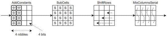
Figure 2.
A round of LED composed by the functions , , and .
. Six bits, , and (initialized to zero), are shifted to the left () and . Those computations are done each round before using the constant. Moreover, the key size (written in its bit form ) is used to create the constant. Then, the values are combined into a round constant (see Matrix constant), and this constant is added (using bitwise exclusive or) to the state.
. The actual state is substituted by the new state using the S-box presented in Table 1. This function adds some confusion and non-linearity during the process.

Table 1.
S-box.
. The rows of the the state are rotated: row i is rotated i positions.
. The state array is post-multiplied by the matrix M (see Matrix M). For the sake of efficiency, we use the matrix A (see Matrix A) with and post-multiply it four times to the state.
After the sstep and AddRoundKey, the state becomes the ciphertext.
Another approach of the cipher is its bitslice version [13], and this approach brings some important properties for this work. Let us suppose that the machine used has 64-bit length registers. Then, the 64-bit state is stored in a single register. The bitslice transformation of the cipher stores the state in 64 registers, each containing 1 bit of data. This approach allows us to have a bit-oriented cipher, rather than a word-oriented one. This is very important for the implementation of the parity scheme.
Another advantage of the bitslice version is the parallel encryptions. In the same conditions as the previous point, instead of using 64 registers containing only 1 bit of useful data, we can encrypt n plaintexts in parallel and then store 64 n-bit useful data. As the bitslice version is bitwise, the cipher cannot interfere between the different states. It is this method that induces detection of any 1-word fault injection. Indeed, as every machine word is seen as the concatenation of a single bit of n states and as any 1-bit injection in a state would be detected, then up to 1-word fault injection could be detected here.
The state transformation is presented in Figure 3 within a blue register of the machine and within a red state of the cipher.
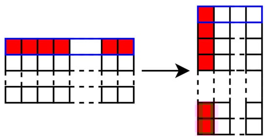
Figure 3.
Bitslice transformation of the state.
3. Error Compensation Issue
In this section, we exhibit a potential fault attack against Friet [9]. Indeed, in particular scenarios, we show that a fault injected can create several errors that can be compensated during the parity check, so the error is not detected. The scenario has a small probability of success, depending on the attack model and some requirements about implementation characteristics. We then present a countermeasure to prevent this kind of attack in a strong model where the adversary can inject the fault of his choice at the position and time one chooses.
3.1. Issue Example
We bring out the vulnerabilities with an example, and we next generalize it. We assume that the attacker can add a fault to one value during the computation.
Let as Friet manipulates 128-bit data. For the sake of simplicity, we call a, b, c, and d the inputs of the operation. For the same reason, , , , and are the outputs of the operation. During these operations, the parity equation followed is . This parity equation is checked to ensure that no fault is injected. We inject the additive fault into the word c during the operation, and, after that, the rotated word c is added to a and to b before the addition. The fault injection is illustrated in Figure 4, with the red line showing the modification.
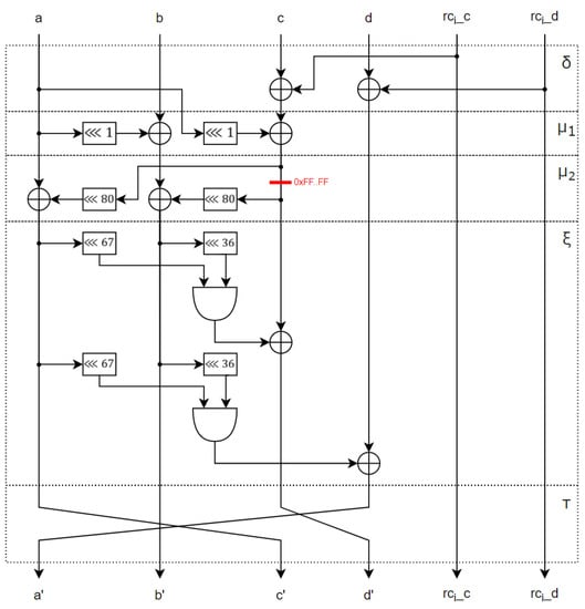
Figure 4.
Round of FRIET-P.
When such a fault is injected, the outputs of two branches are modified: the second b and the third c. We denote and as the second and third words of the output of the faulty operation. Then, we have two equations:
At the output of the faulty , we have . Then, the check subroutine does not detect the injected fault, since the fault on the two branches cancel out when applying a XOR operation on the values.
In the previous example, we saw that the fault is not detected because it remains unchanged with the shift by 80 bits (that is the shift of ). However, this is not the only fault that is not detected with this shift. Indeed, all the faults that remain unchanged with the 80-bit shift have this property. With the Algorithm 1 we can identify all the valid fault that are undetected. Indeed, we begin with the word , and we shift this word by 80 bits, and we test when the word come back to the initial value 1. The cycle length found is 8, and the number of cycles is then . That means that every fault composed by 8 same 16-bit concatenated words is not detected. Thus, we have undetected faults (the value is not a fault) over different faults. In terms of probability, we have a probability around to have an undetected fault. As this probability is very tiny, then with some random faults it is difficult to identify such a weakness. Moreover, the undetected fault is a 128-bit injection, and when the registers are strictly smaller than 128-bit long, then the necessary fault would affect two registers so two faults would be needed. This constraint places the error outside of the study.
| Algorithm 1 Find the length of a cycle. |
|
The same analysis can be done for , and it is easy to see that the only undetected fault is the all 1 fault. For the , the bitwise and between two branches make the fault non-detection probabilistic in function of the data in the second branch.
3.2. Countermeasures
We assume that the registers are wide enough to ensure that the undetected faults are still in the limits of the study. An obvious solution to this issue is to increase the cycle length to limit the number of undetected faults. With a shift of 1 bit, the cycle length is maximum with a value of 128. Indeed, only the words composed by 128 same 1-bit words are undetected. However, the fault remains undetected ( is still not a fault), and we have to modify the former operation to implement our solution.
Another solution must be found to detect all the faults without changing the cryptographic primitives of the cipher. We copy every variable used more than once and check if the copies are equal. A Boolean is used to express the error detection ( obtains the value 0 when an error is detected). With this principle, any fault injected during an operation only affects one copy and is detected before using the copies. The following Algorithm 2 presents the copies and the checks on the operation of the FRIET-P round and shows the overcost of this solution in comparison with the classical FRIET-P presented in Algorithm 3.
| Algorithm 2 Protected operation of the FRIET-P round. |
|
| Algorithm 3 Classical operation of the FRIET-P round. |
|
The overcost of the countermeasure lies on the three copies of the value c and the comparison of these three copies. This solution is used in the rest of the paper to avoid undetected fault injection.
4. Code Abiding on LED
In this section, we present a generic method to apply code-abiding countermeasures to word-oriented block ciphers and illustrate this technique on LED cipher [12]. Word-oriented ciphers are often implemented with tables (S-boxes for the substitution layer and multiplicative tables for the diffusion layer) and with XOR operation on words in the same column. We then need to consider error detection codes at word, column, and state levels.
The basic code is defined at word level and is simply extended to the column and state level. Indeed, the columns and the state are only a concatenation of the words. Thus, if we have a code of parameters at word level, the concatenation of l word is a code of parameters at column level.
The principle of code abiding protection is to apply permutation on different codes. Thus, we have two cases if we apply always permutation to the full state, and then, either we are in the code and stay in the code or we are not in the code and stay outside the code. Since we target only one fault injection, we can at most change one set, and, due to our construction, any single fault injection forces us to change from a word of the code to a word outside the code. The last property is obtained thanks to bitslice representation and check of non-modification when we use the same variable in a different place. (Note that we can hope for security, and fault detection, for multiple random fault with high probability, thanks to parallelism we use). We next present, in more details, the adaptation made for each operation.
4.1. State Modification
Let S be the 64-bit state of the unprotected LED cipher. In order to detect fault, we need to add a redundant part. In our case, we select the 5-bit parity check code. Thus, we need to add a parity bit for each 4-bit nibble of the state. Indeed, if we denote the bit of S, we have: , where are the bits of the nibble i. Eventually, we have a 80-bit state composed of 64 data bits and 16 parity bits.
In the Section 2, we presented the bitslice version of LED. This is the version that is used in this work, and we thus have to add the parity property by adding 16 registers. The Figure 5 illustrates this step within blue for a register of the machine, in red the data bits of a state, and in pink the parity bits of the red state. The code abiding notion is more bit-oriented than word-oriented, and then the bitslice approach allows us to use the code abiding notion on a classical word-oriented cipher.
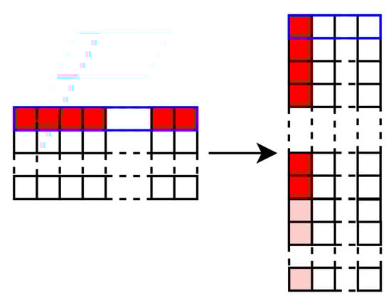
Figure 5.
State after Bitslice and Parity transformations.
These transformation functions are summarized in the following Algorithms 4 and 5.
| Algorithm 4 State S transformed into its bitslice version. |
|
| Algorithm 5 Parity bits added to the bitslice state S. |
|
4.2. Key and Constant
We assume that the key and the constant are stored in an encoded manner.
We copy the key and the constant at the beginning of the computation and use the copy for the all computation at the end, and we check that the copy used stayed unchanged. Thus, any charge in the key during the encryption is detected. Since the attacker can only inject one fault, modification of the key is detected. An adversary that modifies the key may inject fault at each key addition. However, by using copy and checking at the end and thanks to the absence of key schedule in LED-64, the attacker cannot use this method for multiple fault injection.
The only method should be to modify the stored key. However, LED is known for resistance against related key attacks and, thus, no exploitable information can be obtained by the attacker.
If a fault is injected on the key, the XOR operation with the state propagates the error on the state until the parity check of the state.
4.3. AddConstant
We calculate the constant presented in Section 2. This constant is a 64-bit value that we transform into 80 n-bits values (bitslice + parity transformations) that are computed to the state using XOR operation. If n encryptions are performed in parallel, the constant must fit the n-bit length of the registers, and then the 80 bits have to be duplicated n times. This is illustrated in Algorithm 6 ( is composed by ).
| Algorithm 6 Constant c bitsliced and duplicated. |
|
If a fault is injected on the constant, the error is propagated on the state until the check parity function.
4.4. ShiftRows
This function is the same operation as the former operation. The parity bits are shifted among the nibble from which they have been computed. The bit is shifted bits to the left. This is illustrated in Figure 6.
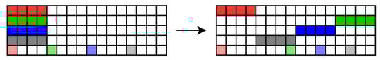
Figure 6.
ShiftRows on the bitslice parity state.
During this operation, a fault can be injected on the state and stays on it until its detection. Moreover, as the state is only shifted, its value remains the same, then a fault injected before the operation is propagated on the output.
4.5. SubCells
The substitute operation brings confusion and non-linearity to encryption. It is then a critical function of the block cipher construction. The extension from the code to the code requires us to represent the 4-bit S-box by a 5-bit S-box, and this projection brings a choice of the 5-bit S-box.
We present, in Section 5, a way to construct the protected S-box. Here, we present the results on the S-box represented by the Table 3. However, we use an alternative form of the S-box composed only by logical gates, the algebraic normal form. This form gives five equations, where is the bit of the input and the bit of the output ( are the data bits and is the parity bit).
This function is presented in Algorithm 7. We can denote the copies of the values used more than once to avoid error compensation presented in Section 3, and as the bit is used only in the last two equations, this bit is copied only twice. Indeed, the output only lies on the values , and then a fault is injected on a copy only affecting one output, and the parity characteristic allows the error detection.
| Algorithm 7 function. |
|
If a fault is injected before or during the function, and the separation of the codes in the S-box representation keeps the word out of the code , and the fault is propagated into the space.
4.6. MixColumnsSerial
This operation is composed by the four post-multiplications with the matrix A (see Section 2). The state is decomposed into four columns of four 5-bit nibbles each. These nibbles are the 4-bit data and the parity bit associated. In our operation, only a multiplication by two is used (a multiplication by four is just two multiplications by two). The Algorithm 8 show the multiplication by two operation. This operation is a shift of the bits and a XOR with the LSB of the data word on the second bit of the nibble. The computation on the parity bit is thus only a XOR with this LSB.
| Algorithm 8 Multiplication by 2. |
|
The Algorithm 9 presents the state divided into columns and the multiplication with the matrix A. Same as in the function, we create a copy of each element used more than once to avoid a future error compensation.
With the same observations than the previous operations, if a fault is injected before or during the operation, this error is propagated through the operation on the state.
All the LED functions are converted into code abiding functions to keep the parity characteristic of the state and to allow the fault injection detection. The next section focuses on the 5-bit representation of a 4-bit S-box.
| Algorithm 9 function. |
|
5. 5-Bit Representation of a 4-Bit S-Box
In the protected version of LED, the function uses a 5-bit representation of the S-box. This section presents how to create a 5-bit representation from a 4-bit permutation and which representation is the best in terms of cost optimization.
In the last section, the function requires a representation on 5 bits of the 4-bit . The former 4-bit S-box must remain the same with the parity bit added at the end of the words. Indeed, the 5-bit representation is already half filled with the words with an even parity (see Table 2). Then, we have candidates to represent a 4-bit S-box. We must find a way to compare one candidate from another.
Table 2.
5-bit S-box derived from to fill.
Only the S-boxes that correspond to permutations are considered (each output has one and only one related input). Indeed, the parity code used is the 5-bit parity code , but, as we want to consider this code at the state level, the resulting code is selected. is only a concatenation of 16 codes . This concatenation brings the constrains of the permutations on the S-boxes.
5.1. Score Function
To compare the candidates, a score to the S-boxes must be attributed and the best score among the candidates is selected. In this work, a focus on the implementation cost is realized. Then, the score of a candidate is the number of logic gates needed to construct the S-box. The algebraic normal form (ANF) of the S-box is used to count the number of AND and XOR gates. With the score function presented in Algorithm 10, the best representation on 5 bits is the S-box with the lowest number of logical gates. The next subsection is the application of the score function to every representation on 5 bits of a 4-bit S-box.
| Algorithm 10 Score of a S-box S. |
|
5.2. Exhaustive List
To fill the 5-bit S-box, a candidate must be selected among all the permutations. The obvious way to choose the best S-box is to score every candidate and to keep the one with the lowest score. This process is summarized in Algorithm 11 and is the most precise way to find the lowest score. Indeed, we would have the score of each function and then select the best one according to the criteria of implementation cost. However, it requires us to browse all of the permutations, and this can be a very long task. A new solution based on the construction of the 5-bit representation can be as efficient and very easier to achieve.
| Algorithm 11 Selection of the S-box with the lowest number of gates. |
|
5.3. Construction
A new selection method is introduced with a construction approach instead of an exhaustive approach. In this paragraph, an even word denotes a word that verifies the parity characteristic, and an odd word is one which does not. Every even word is only 1 bit away from an odd word. The LSB is used to separate an even from an odd word ( and are only 1 bit away from each other, and this bit is the LSB). Each even input is substituted by an even output, and each odd input is substituted by an odd output. The 5-bit S-box is constructed with the following rule: an odd input is substituted by the odd word 1-bit away from the even output linked to the even input 1-bit away from the odd input. Indeed, each even pair of input/output have a 1-bit away odd pair of input/output. This construction is explained in the Algorithm 12. With this method, the representation of PRESENT is shown in Table 3 and consists of 62 logical gates. Several S-Boxes (found with an exhaustive search) with good cryptographic properties were tested, and none has an ANF constructed with less than 94 logical gates (the biggest one was created with 124 logical gates). We now have to test the robustness of the protected cipher.
| Algorithm 12 Construction of a code abiding 5-bit representation from a 4-bit S-box. |
|
Table 3.
5-bit code abiding representation constructed from .
6. Experimental Results
This section presents the various tests done on the protected LED to determine its robustness against fault injection.
6.1. Robustness
To test the robustness of the protected LED cipher, three scenarios are tested. The detection of a fault injected simply sets a variable to 0. During the tests, the fault injection is simulated, so there is no case where a fault does not create an error.
- Scenario 1: A bit of the state is toggled at a random place of the state and at a random moment of the encryption. This bit-flip induces a change on the parity characteristic of the nibble where it belongs. With the code abiding properties of the functions used during the encryption, the error persists until the parity check function and thus is always detected.
- Scenario 2: A bit of the key or of the constant of the function is toggled at a random place and a random round of the encryption. As the XOR operation is a code abiding operation, the fault is transmitted from the constant to the state and persists until the parity check. The error is thus always detected.
- Scenario 3: A fault is injected on data used more than once during a function at a random place and a random round of the encryption. The copies done before the use of the data are then not equal, and the test sets the to 0. The fault is thus always detected.
In all the scenarios, the fault is always detected, and then the code abiding solution is robust against 1-bit fault attack.
In all the scenarios, 1,000,000 faults have been injected, and the countermeasure (combining code abiding property and copies of the elements used more than once) always leads to a fault detection. The code abiding solution is then robust against 1-word fault attack. The results are presented in Table 4.
Table 4.
Robustness results of the secured implementation.
6.2. Overcost of the Countermeasure
Adding the parity scheme to the LED cipher has a cost. Indeed, we convert an encryption algorithm working on 4-bit words to an encryption algorithm working on 5-bit words. Thus, the new round functions have a bigger price than the former ones. Moreover, our n states are 80-bit long instead of 64-bit long (we encrypt n plaintexts in parallel, and in the tests, we fix ). Thus, our implementation takes a bigger place in the memory and one secure encryption takes longer than an unprotected encryption. We differentiate several implementations: the classical implementation refers to the soft implementation using lookup tables; the bitslice is the bitslice version of LED without any protection; the code abiding implementation is the addition of the parity bit during the encryption; and the code abiding + copies implementation combines the code abiding properties with copies of values used more than once. The cost can be summarized in the Table 5. The compiler used was the GNU GCC Compiler without any optimization. The CPU used is the Intel Core i5 CPU. The results are presented as a ratio to have a better understanding of the overcost of countermeasures from one implementation to another. The results a must be put into perspective as the classical implementation encrypts only one plaintext at the time when the other implementations can encrypt up to 64 plaintexts at the same time (on a 64-bit length machine). The overcost of the code abiding countermeasure is then better than expected. Indeed, in terms of time overcost, a 25% rise was expected (25% more bits are computed) when an only 12% is measured. However, with the copies countermeasure, an overcost of 79% is reached.
Table 5.
Implementation results and cost comparison of the encryptions.
Moreover, another comparison on each round function allows us to precisely understand where the countermeasure has the biggest impact (see Table 6). The heaviest functions from the classical implementation to the other ones are clearly the , as the function does not use any lookup table and the as the constant used must be transformed into a bitslice and parity constant. However, as mentioned before, it is more interesting to compare the bitslice versions as they encrypt the same number of plaintexts and are based on the same principles. With these comparisons, the biggest overcost is the function with all the copies brought.
Table 6.
Implementation results and cost comparison of the round functions.
7. Conclusions
The principle used in this work to prevent fault injections is to detect them using an error detecting code, the parity bit code. This code relies on a redundancy of the information contained in a word. The parity bit code used is the 5-bit parity code, with 4 data bits and 1 parity bit. This method allows us to detect a 1-bit fault injection on a value during an operation.
This work lightens an issue induced by an error compensation. Indeed, depending on the operation performed, an error injected on a value can be propagated into several computed outputs and with the parity bit code, and this error may compensate with its multiple occurrences. The first step is then to present the conditions on the fault and on the operation to reach the compensation, and then to propose a countermeasure to this error compensation that lies on copying the values used more than once and check for equality of the copies.
In addition to this first measure, a method is presented to apply code-abiding notion to word-oriented ciphers. An example on the LED cipher shows the transformations of the state and the round functions to include the parity bit code to the operations. A protected version of the existing LED cipher is then created. Its robustness against 1-bit fault injection is tested, and the results validate its security. Moreover, with the bitslice method, the robustness reaches 1-word fault injection detection.
The next step is to extend this method to a generic one to include code abiding to new cryptographic primitives. A critical operation is the S-box used, and the projection of this S-box into a larger space to add the parity bit brings many candidates. A way to differentiate them is to give them a score based on their implementation cost and select the cheapest S-box.
Eventually, future works could focus on applying the code-abiding method to a larger cipher, such as AES, rather than lightweight ciphers, as well as to evaluate the overcost of the countermeasure compared to other error detecting solutions. Moreover, 1-bit error detection has its limitations [14], and a work on multiple faults detection and correction would be interesting.
Author Contributions
Conceptualization, P.-A.T. and V.G.; methodology, P.-A.T.; software, P.-A.T.; validation, P.-A.T.; investigation, P.-A.T.; writing—original draft preparation, P.-A.T.; writing—review and editing, P.-A.T., L.B. and V.G.; visualization, P.-A.T.; supervision, L.B. and V.G.; project administration, L.B.; funding acquisition, L.B. All authors have read and agreed to the published version of the manuscript.
Funding
Part of this was support by the French Agence Nationale de la Recherche under the grant ANR-22-CE39-0008 (project PROPHY).
Institutional Review Board Statement
Not applicable.
Data Availability Statement
Not applicable.
Conflicts of Interest
The authors declare no conflict of interest.
Abbreviations
The following abbreviations are used in this manuscript:
| CA | Code Abiding |
| CA + Copies | Code Abiding with copies included |
References
- Biham, E.; Shamir, A. Differential Fault Analysis of Secret Key Cryptosystems. In Lecture Notes in Computer Science, Proceedings of the Advances in Cryptology—CRYPTO’97, 17th Annual International Cryptology Conference, Santa Barbara, CA, USA, 17–21 August 1997; Kaliski, B.S.K., Jr., Ed.; Springer: Berlin/Heidelberg, Germany, 1997; Volume 1294, pp. 513–525. [Google Scholar] [CrossRef]
- Kocher, P.C.; Jaffe, J.; Jun, B. Differential Power Analysis. In Lecture Notes in Computer Science, Proceedings of the Advances in Cryptology—CRYPTO’99, 19th Annual International Cryptology Conference, Santa Barbara, CA, USA, 15–19 August 1999; Wiener, M.J., Ed.; Springer: Berlin/Heidelberg, Germany, 1999; Volume 1666, pp. 388–397. [Google Scholar] [CrossRef]
- Baksi, A.; Bhasin, S.; Breier, J.; Chattopadhyay, A.; Kumar, V.B.Y. Feeding Three Birds With One Scone: A Generic Duplication Based Countermeasure To Fault Attacks. In Proceedings of the Design, Automation & Test in Europe Conference & Exhibition, DATE 2021, Grenoble, France, 1–5 February 2021; pp. 561–564. [Google Scholar] [CrossRef]
- Breier, J.; Hou, X.; Liu, Y. On Evaluating Fault Resilient Encoding Schemes in Software. IEEE Trans. Dependable Secur. Comput. 2021, 18, 1065–1079. [Google Scholar] [CrossRef]
- Kiaei, P.; Mercadier, D.; Dagand, P.; Heydemann, K.; Schaumont, P. Custom Instruction Support for Modular Defense Against Side-Channel and Fault Attacks. In Lecture Notes in Computer Science, Proceedings of the Constructive Side-Channel Analysis and Secure Design—11th International Workshop, COSADE 2020, Lugano, Switzerland, 1–3 April 2020; Revised Selected Papers; Bertoni, G.M., Regazzoni, F., Eds.; Springer: Berlin/Heidelberg, Germany, 2020; Volume 12244, pp. 221–253. [Google Scholar] [CrossRef]
- Lee, S.; Jho, N.; Kim, M. Table Redundancy Method for Protecting Against Fault Attacks. IEEE Access 2021, 9, 92214–92223. [Google Scholar] [CrossRef]
- Patrick, C.; Yuce, B.; Ghalaty, N.F.; Schaumont, P. Lightweight Fault Attack Resistance in Software Using Intra-instruction Redundancy. In Lecture Notes in Computer Science, Proceedings of the Selected Areas in Cryptography-SAC 2016—23rd International Conference, St. John’s, NL, Canada, 10–12 August 2016; Revised Selected, Papers; Avanzi, R., Heys, H.M., Eds.; Springer: Berlin/Heidelberg, Germany, 2016; Volume 10532, pp. 231–244. [Google Scholar] [CrossRef]
- Regazzoni, F.; Eisenbarth, T.; Breveglieri, L.; Ienne, P.; Koren, I. Can Knowledge Regarding the Presence of Countermeasures Against Fault Attacks Simplify Power Attacks on Cryptographic Devices? In IEEE Computer Society, Proceedings of the 23rd IEEE International Symposium on Defect and Fault-Tolerance in VLSI Systems (DFT 2008), Boston, MA, USA, 1–3 October 2008; Bolchini, C., Kim, Y., Gizopoulos, D., Tehranipoor, M., Eds.; pp. 202–210. [CrossRef]
- Simon, T.; Batina, L.; Daemen, J.; Grosso, V.; Massolino, P.M.C.; Papagiannopoulos, K.; Regazzoni, F.; Samwel, N. Friet: An Authenticated Encryption Scheme with Built-in Fault Detection. In Lecture Notes in Computer Science, Proceedings of the Advances in Cryptology-EUROCRYPT 2020—39th Annual International Conference on the Theory and Applications of Cryptographic Techniques, Zagreb, Croatia, 10–14 May 2020; Part I, Canteaut, A., Ishai, Y., Eds.; Springer: Berlin/Heidelberg, Germany, 2020; Volume 12105, pp. 581–611. [Google Scholar] [CrossRef]
- Bertoni, G.; Breveglieri, L.; Koren, I.; Maistri, P.; Piuri, V. A Parity Code Based Fault Detection for an Implementation of the Advanced Encryption Standard. In Proceedings of the 17th IEEE International Symposium on Defect and Fault-Tolerance in VLSI Systems (DFT 2002), Vancouver, BC, Canada, 6–8 November 2002; pp. 51–59. [Google Scholar] [CrossRef]
- Lac, B.; Canteaut, A.; Fournier, J.J.A.; Sirdey, R. Thwarting Fault Attacks using the Internal Redundancy Countermeasure (IRC). IACR Cryptol. ePrint Arch. 2017, 910, 1–26. [Google Scholar]
- Guo, J.; Peyrin, T.; Poschmann, A.; Robshaw, M.J.B. The LED Block Cipher. In Lecture Notes in Computer Science, Proceedings of the Cryptographic Hardware and Embedded Systems-CHES 2011—13th International Workshop, Nara, Japan, 28 September–1 October 2011; Preneel, B., Takagi, T., Eds.; Springer: Berlin/Heidelberg, Germany, 2011; Volume 6917, pp. 326–341. [Google Scholar] [CrossRef]
- Bao, Z.; Luo, P.; Lin, D. Bitsliced Implementations of the PRINCE, LED and RECTANGLE Block Ciphers on AVR 8-Bit Microcontrollers. In Lecture Notes in Computer Science, Proceedings of the Information and Communications Security—17th International Conference, ICICS 2015, Beijing, China, 9–11 December 2015; Revised Selected Papers; Qing, S., Okamoto, E., Kim, K., Liu, D., Eds.; Springer: Berlin/Heidelberg, Germany, 2015; Volume 9543, pp. 18–36. [Google Scholar] [CrossRef]
- Colombier, B.; Grandamme, P.; Vernay, J.; Chanavat, É.; Bossuet, L.; de Laulanié, L.; Chassagne, B. Multi-Spot Laser Fault Injection Setup: New Possibilities for Fault Injection Attacks. In Lecture Notes in Computer Science, Proceedings of the Smart Card Research and Advanced Applications—20th International Conference, CARDIS 2021, Lübeck, Germany, 11–12 November 2021; Revised Selected, Papers; Grosso, V., Pöppelmann, T., Eds.; Springer: Berlin/Heidelberg, Germany, 2021; Volume 13173, pp. 151–166. [Google Scholar] [CrossRef]
Disclaimer/Publisher’s Note: The statements, opinions and data contained in all publications are solely those of the individual author(s) and contributor(s) and not of MDPI and/or the editor(s). MDPI and/or the editor(s) disclaim responsibility for any injury to people or property resulting from any ideas, methods, instructions or products referred to in the content. |
© 2023 by the authors. Licensee MDPI, Basel, Switzerland. This article is an open access article distributed under the terms and conditions of the Creative Commons Attribution (CC BY) license (https://creativecommons.org/licenses/by/4.0/).