Article

Low-Cost Hardware in the Loop for Intelligent Neural Predictive Control of Hybrid Electric Vehicle

by
Mohamed El-Sayed M. Essa
1,*,
Joseph Victor W. Lotfy
2,
M. Essam K. Abd-Elwahed
2,
Khaled Rabie
3,4,
Basem M. ElHalawany
5,6 and
Mahmoud Elsisi
6,7,*
1
Electrical Power and Machines Department, Institute of Aviation Engineering and Technology (I.A.E.T), Egyptian Aviation Academy, Imbab Airport, Giza 12815, Egypt
2
Electronics and Communication Department, Institute of Aviation Engineering and Technology (I.A.E.T), Egyptian Aviation Academy, Imbab Airport, Giza 12815, Egypt
3
Department of Engineering, Manchester Metropolitan University, Manchester M1 5GD, UK
4
Department of Electrical and Electronic Engineering Technology, University of Johannesburg, Johannesburg 2006, South Africa
5
Department of Electronics and Communication Engineering, Kuwait College of Science and Technology, Kuwait City 13133, Kuwait
6
Department of Electrical Engineering, Faculty of Engineering (Shoubra), Benha University, Cairo 11629, Egypt
7
Department of Electrical Engineering, National Kaohsiung University of Science and Technology, Kaohsiung City 807618, Taiwan
*
Authors to whom correspondence should be addressed.
Electronics 2023, 12(4), 971; https://doi.org/10.3390/electronics12040971
Submission received: 23 December 2022 / Revised: 7 February 2023 / Accepted: 9 February 2023 / Published: 15 February 2023
(This article belongs to the Special Issue Fault Diagnosis and Control Technology of Electric Vehicle)

Abstract

:
The design and investigation of an intelligent controller for hardware-in-the-loop (HIL) implementation of hybrid electric vehicles (HEVs) are proposed in this article. The proposed intelligent controller is adopted based on the enhancement of a model predictive controller (MPC) by an artificial neural network (ANN) approach. The MPC-based ANN (NNMPC) is proposed to control the speed of HEVs for a simulation system model and experimental HIL test systems. The HIL is established to assess the performance of the NNMPC to control the velocity of HEVs in an experimental environment. The real-time environment of HIL is implemented through a low-cost approach such as the integration of an Arduino Mega 2560 and a host Lenovo PC with a Core i7 @ 3.4 GHz processor. The NNMPC is compared with a proportional–integral (PI) controller, a classical MPC, and two different settings of the ANN methodology to verify the efficiency of the proposed intelligent NNMPC. The obtained results show a distinct behavior of the proposed NNMPC to control the speed of HEVs with good performance based on the distinct transient response, minimum error steady state, and system robustness against parameter perturbation.

1. Introduction

Electric vehicles have a long history of development and will continue to do so. Based on a disposable battery, they were first manufactured around 1830 [1]. They were improved in 1881 with the first electric vehicle (EV) based on a rechargeable battery. In addition, the first EV operated via a small electric motor was made in 1898 [1]. In fact, electric vehicles had more drawbacks than internal combustion engine (ICE) vehicles, such as the inability to reach high speeds. In addition, the capacity of the battery was very small compared to an ICE’s tanks [2]. Due to gasoline and oil shortages, the electric vehicle industry began again in the twenty-first century [3]. Furthermore, the use of EVs is increasing in order to help the environment by reducing carbon pollution. As a result, consumers returned to using EVs based on improvements to keep up operations compared to ICE cars [1,2,3].
EVs are classified into three main types based on their power supplies [4]. The types are battery electric vehicles (BEVs), hybrid electric vehicles (HEVs), and plug-in hybrid electric vehicles (P-HEVs). Battery-based chargers and electric motors are examples of BEVs. However, the HEV has the advantage of combining a traction motor with an ICE to push and move the vehicle. In HEVs, a system of regenerative braking is used to recharge the disposable battery. The P-HEV is similar to the HEV, but it has the difference that the batteries in the P-HEV are rechargeable through an external electric source. The speeds of EVs are very slow compared with ICE vehicles. As a result, researchers were forced to merge EVs with ICE vehicles in order to facilitate operation with a different source. However, control of the resultant HEV type became harder. Therefore, HEVs are a remarkable research field that can present a solution for decreasing oil and gas consumption, reducing pollution, and increasing the speed of EVs [1,2,3,4]. Recently, the research area of HEV control has grown rapidly.
The HEV is an interesting research point for many scientific researchers. The PID controller is commonly used for many applications, such as HEVs. Reference [5], the PID is applied to the DC motor of HEVs to control the speed. Furthermore, the HEV was studied with a DC motor and mechanical engine to control the speed using a PID controller [6]. The objectives of the HEV [6] are to maximize efficiency and reduce carbon. A control system for the speed of an HEV-based DC motor using a microcontroller card as the electronic control unit of the vehicle is demonstrated in [7]. The control design was developed using a PID controller and realized based on a prototype that integrated different types of sensors [7]. The optimal sharing of consumed energy between an ICE and the battery source that feeds the motor was studied [8]. Additionally, the two sources are recommended to operate in their efficient regions. Reference [8], the energy management approach is improved based on a neural network and fuzzy logic strategy for HEVs. In addition, fuzzy logic techniques are proposed as a control strategy for HEVs [9]. In addition, the genetic algorithm (GA) is utilized to obtain the optimal minimum fuel consumption and decrease the level of emissions [9]. The authors of [10] introduced a comparative study based on different performance tests to show the effectiveness of applying different control techniques such as PID, H∞, and fuzzy controllers for nonlinear HEVs. Sliding mode control is applied to achieve the required torque set point of the clutch transmission [11]. Moreover, the actual torque is estimated based on the PI observer in [11]. Particle swarm optimization is used to find the optimal parameters of a fractional order PID controller to track the position of the DC motor clutch in [12]. The FO-PI was introduced by the authors of [13] to achieve better control performance at lower speeds with high torque per ampere as a motor output, where it was experimentally proven to be a better indirect field-oriented control method for induction motors. The research in [14] presents several economic variables of hybrid power train systems to demonstrate the effectiveness of MPC-based online energy management. The article [15] shows a two-level MPC for HEVs, where it has been used to gain the finest control strategy concerning the energy consumption method. Furthermore, the simulation results revealed savings of up to 39% when compared to commercial solutions [16]. A study of the series type of HEVs is discussed based on the development of energy management by an MPC in [17]. The article [18] introduced different control techniques to maintain the required motor speed using an electronic throttle control system [18]. The damping speed oscillations represented an important issue for HEVs, as discussed in [19]. As a result, the methodology of the fuzzy-PID controller is adopted to solve this problem [19]. Batteries are a very important component for HEVs, whether pure electric or hybrid types, as they are an essential and important source of power for HEVs. Many studies concerned with improving the performance of batteries have been carried out, such as improving the charging rate of these batteries or increasing the capacity of the batteries to give the vehicles a longer supply period [20,21,22]. A detailed review study on the most important types of batteries and the ones most widely applied in HEVs, which are lithium-ion batteries, was discussed in [20]. Another review study on the chemistry of batteries and the analysis of the chemistry of cells and materials used in batteries is given in [21]. One of the most important research topics is the recycling of batteries and its impact on sustainable development, as presented in [22].
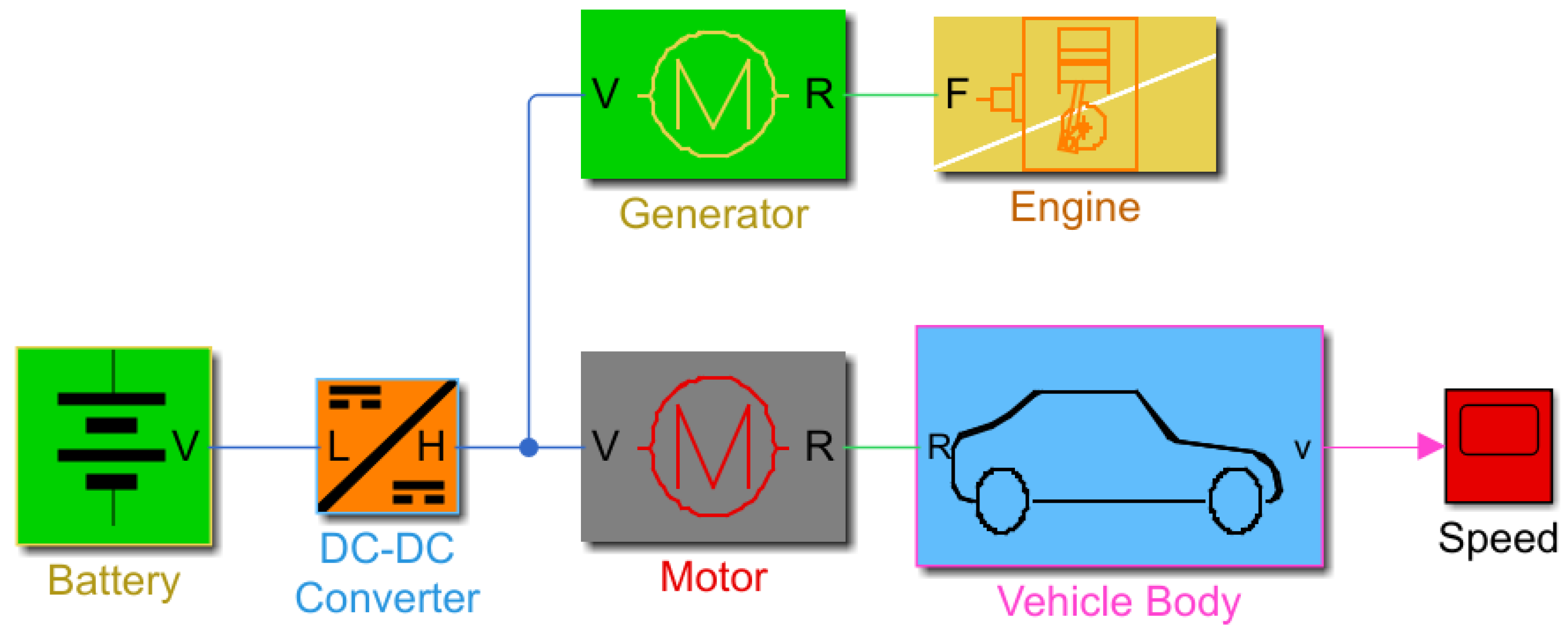
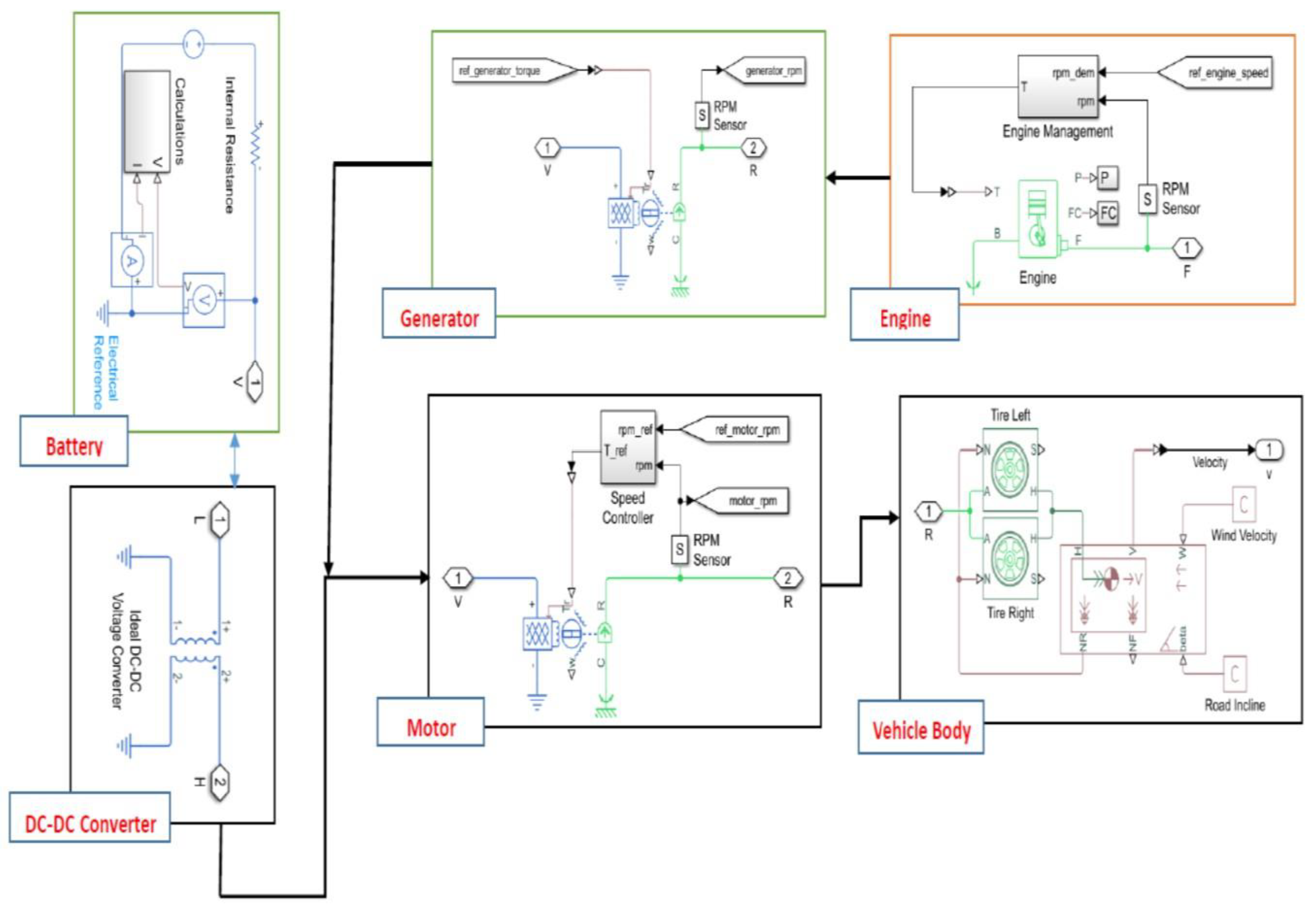
In this paper, the suggested type of HEV is a series HEV. A series drivetrain is used to achieve hybrids, in which only the electric motor gives mechanical power [2,3,6,9,10,11,17]. The motor is operated by either an engine-powered generator or a battery pack. The simplest hybrid configuration is a series drivetrain. In a series hybrid, the motor is the sole source of power that drives the wheels. An electronic card is used to estimate how much power is drawn from the engine or generator, or battery pack. In addition to the engine or generator, regenerative braking can be used to recharge the battery. The series type operates with good performance during go-and-stop traffic, where engines are considered inefficient [2,3,6,9,17]. The electronic card can control the operation of the motor by using the battery feed only, which will allow the engine to work in the operations in which it is better and more efficient. The batteries in the series type are considered more effective than the engine, so the engine is typically small. Due to the importance of the electrical part in HEVs, the focus of this research was on the design of speed control through the electric motor. As a result, the system was considered single input, single output (SISO) despite being multi-input, multi-output (MIMO). The rest of the paper is structured as follows. Section 2 discusses the system modeling. 
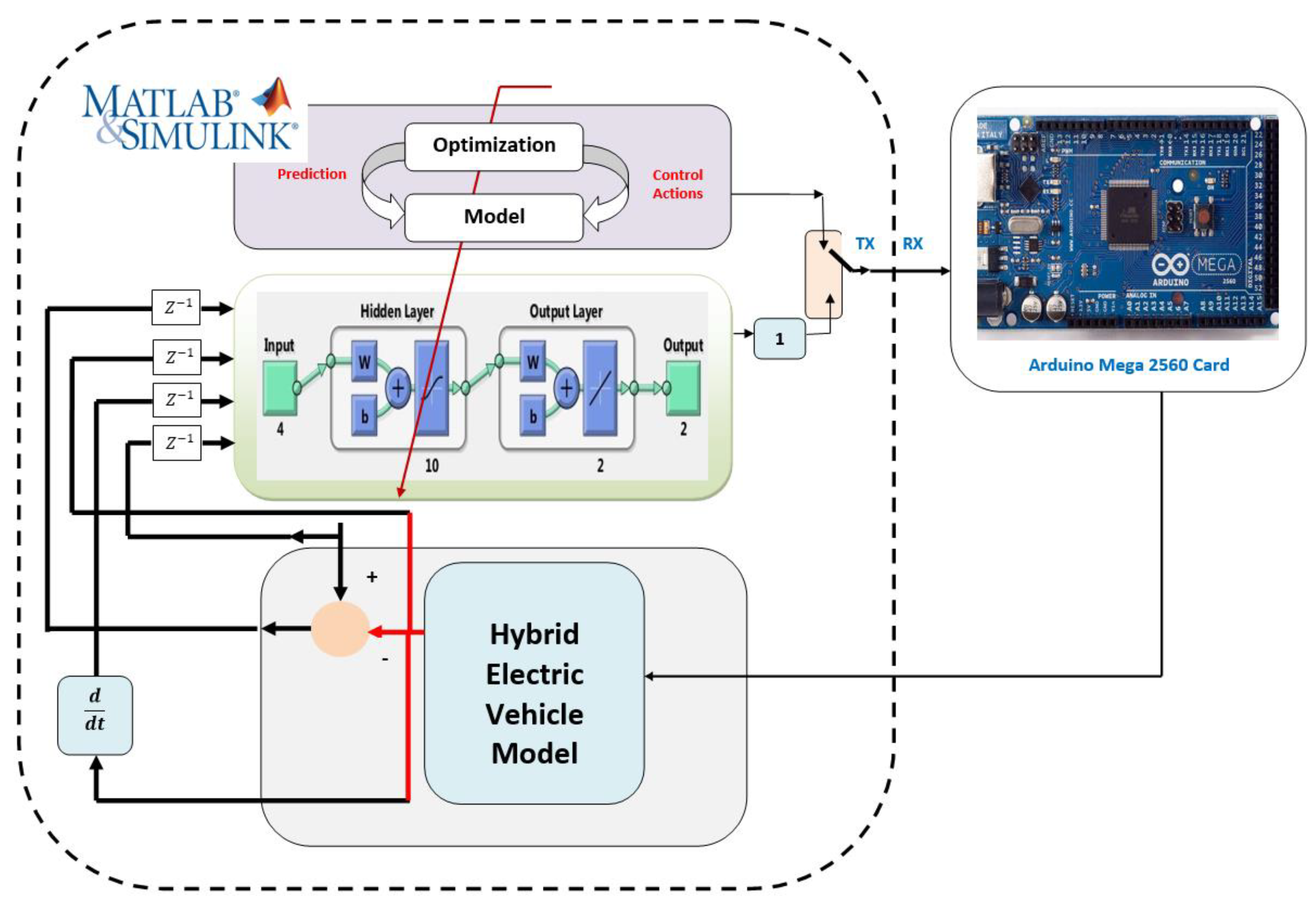
Section 3 presents the implementation of hardware in the loop, and 
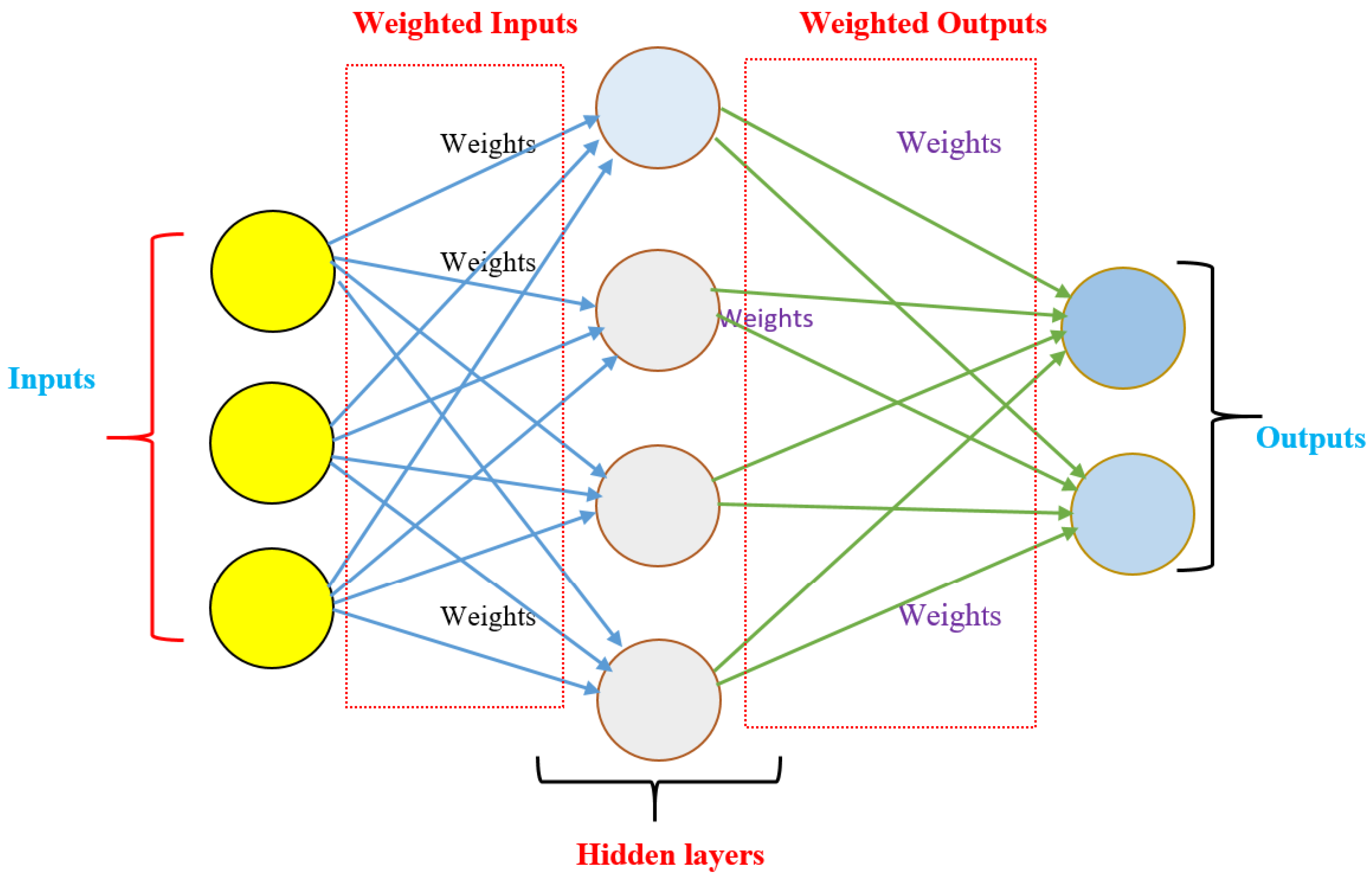
Section 4 demonstrates the structure and behavior of the ANN. In addition, Section 5 introduces the MPC. Finally, the results and conclusion are given in Section 6 and Section 7, respectively. The contributions of the paper can be summarized as follows:
  • Implementing an experimental HIL for HEVs to validate the performance of the proposed controller.
  • Designing a robust NNMPC for simulation and experimental speed control of HEVs.
  • Evaluating the proposed controller based on different performance criteria.
  • Comparing simulation and experimental results for speed control of HEVs.
  • Comparing the proposed NNMPC with the PI and MPCs.

2. System Modeling

The mathematical description of HEVs is categorized into two main parts [10,11,12,13,14,15,16,17,18,19]. The first is related to mechanical components in the vehicle such as the engine and the dynamics of the vehicle body. However, the second part is related to electrical equipment such as batteries, DC-DC converters, motors, and generators. The studied architecture of a series hybrid transmission vehicle is shown in Figure 1. The produced mechanical power is converted to electrical energy through generation, as depicted in the block diagram in Figure 1. The generator feeds the DC network with a constant power flow that is taken from the vehicle engine. The power is drawn from the battery by the electrical motor to accelerate the vehicle, which subsequently utilizes regenerative braking to supply that power back to the electrical battery. The MATLAB/Simulink model of the HEV is given in Figure 2. The model of the HEV in this article was built using physical blocks in MATLAB/Simulink for different components of the vehicle. The parameters of the physical blocks are given in Table 1, Table 2, Table 3, Table 4, Table 5, Table 6 and Table 7.

2.1. Calculation Block

The calculation block in the battery model is used to calculate the power of the battery; sensors measure the voltage and current, which are then multiplied to display this power (Power (P) = Current (I)∗Voltage (V)). It also provides the lost power by squaring the current and multiplying the internal resistance of the battery ( P l o s s e s = I 2 R ). In addition, we can monitor the battery charging rate.

2.2. Purpose of Engine Management

The system of engine management is used in the vehicle to arrange the operation of the devices for controlling the engine’s behavior. In practical systems, it prevents the starting of the engine in case the vehicle is stolen. In addition, it can shut down the vehicle when the power is not needed. The system of engine management provides the correct fuel ratios and timing for every case.
The engine speed can be controlled by controlling the air–fuel intake for combustion in the cylinder. The air–fuel intake is determined by the throttle opening. The engine is controlled via a proportional controller (Kp = 1 × 10⁻³).
The dynamic model for the vehicle is given in Equation (1) [19].
T v = r w η   ( W   S i n   β + f W cos β + 1 2   ρ C d A v 2 + W g d v d t )
The parameters in Equation (1) are described in Table 1.
In the engine, the crankshaft is modeled with the equilibrium equation of motion as in Equation (2) [10,11,12,13,14,15,16,17,18,19].
[ J f + J m ( θ ) ]   ω ˙ + 1 2 d ( θ ) d θ J m ω 2 = T e = T i T f T l
where ω is crankshaft rotatory speed, T i   stands for the torque due to gas pressure, T l   is   load   torque ,   T f is friction torque.
The battery is described with the following equation:
V = V 0 ( SOC 1 β ( 1 SOC ) )
where V 0 is nominal voltage, SOC is the state of charge, and β is a constant depending on battery operation.
The DC-DC converter is simplified and modeled by
v = v ref i load   D + i load   R out
where   R out is based on losses, v ref is the side of the load voltage command, D is a specified value for the output voltage, i load   is the load current.
P e l e c = P l o s s e s + ω τ e l e c
I = P e l e c V
where τ e l e c is the saturated demand torque, P e l e c and P l o s s e s are the used electrical power and the power losses during operation, respectively. V and I are voltage and current at the terminal, respectively. The values of the vehicle components are defined in Table 2, Table 3, Table 4, Table 5, Table 6 and Table 7. The motor type used in this study is a brushless DC motor (BLDC).

3. Hardware in The Loop (HIL)

Hardware in the loop is a test methodology that is applied to give more real-time embedded control (see Figure 3). It is proposed to save cost and effort and improve the effectiveness of systems [23,24,25,26,27]. Additionally, it is adopted to check how intelligently devices will act with real-life systems and to ensure safety for real-life system operations. Due to the discussed benefits of HIL, most HIL fields are related to automotive and aerospace applications [23,24,25,26,27,28]. As a result, it behaves better than pure software testing, as it has better coverage. Unlike the old systems approach, which required waiting until the system was completed and integrated into its final form before beginning testing and identifying issues, testing can begin right away. Figure 3 shows the HIL investigation based on the Arduino Mega 2560. Testing controllers are expensive and unsafe, so the HIL is used to replace controllers where sensors, transducers, and actuators are simulated wherever all inputs/outputs (I/Os) are being tested by representing real-time response and virtual environment simulations [25,26,27]. MATLAB/Simulink is often used to model these environments with all the connected I/Os to verify if the component is fit for its purpose. In this paper, the control design for HEV-based HIL is proposed to describe how the validation of the HIL signaling model has been used through the Arduino Mega 2560 to obtain a more accurate simulation (closed loop system) with different scenarios and to test the suggested intelligent controllers.

4. Artificial Neural Network (ANN)

The ANN is an algorithmic structure inspired by human brains that consists of multiple layers (see Figure 4): one for input, one or more hidden layers, and one for output [29,30,31,32,33]. Each node (artificial neuron) has its own threshold, which activates whenever the data exceed that threshold and moves them to the next layer of this network [29,30,31,32,33]. It learns from training data that consist of inputs and outputs and improves their accuracy over time. Hence, an adaptive system is created and improved continuously [31,32,33]. The significance of ANNs can be summarized by the fact that they can execute different tasks at the same time and operate with lacking knowledge. Additionally, they are commonly utilized in applications of control, as suggested in this paper, due to their tractability with collected data. As a result, it is recommended to build a nonlinear model and very complicated relations [32,33].
In this study, the data used for the training process of the ANN were collected via four inputs and one output. Delayed setpoint speed with one sample, error of system and its change, and delayed actual speed with one sample are the four inputs suggested. IN addition, the actual speed of the vehicle is proposed as the output of the ANN.

5. Model Predictive Controller (MPC)

Model predictive control is able to control the system through the error signal resulting from the difference between the desired behavior and the output of the sensors used to measure the system’s reaction to the desired signal. Furthermore, it is used to predict the future output of the plant by calculating data and for optimizing future control actions [14,15,16,17]. It is considered an advanced control method that is applied efficiently and successfully in many applications. It is dependent on three key processes, such as optimization, summarizing, and correcting feedback signals [14,15,16,17].
The MPC bases its decision on a linear system model. In this paper, it is used for a single input, single output (SISO) system, and it can be tested experimentally with different control laws to monitor the resulting system output via MATLAB/Simulink-based HIL. The MPC parameters are listed in Table 8.
The MPC is governed based on cost function and constraints as given below.
C ( k ) = i = 1 P Q . [   y ^ ( k + i | k )   r ( k + i | k ) ] 2 + i = 0 M 1 R . [ Δ u ( k + i | k ) ] 2 + i = 1 P Q 1 . [ u ( k + i | k ) ] 2
Subject to
y min     y ^ ( k + i | k )     y max
u min u ( k + i | k )     u max
Δ u min Δ u ( k + i | k )     Δ u max
where P and M are prediction control variables. k is time of the discrete signal, i is an index. y ^ , u , Δ u are forecasted output, best control parameter, and change in rate of the control parameter, respectively. The state space model used to build the expected signal in the MPC is formulated in the following Equation (11).
A = [ 1.8911 1.0638 0.1726 1.000 0 0 0 1.000 0 ] ,   B = [ 1 0 0 ] C = 10 3 × [ 0.0612 0.1622 0.0255 ] ,   D = 0

6. Results

Speed control for a simulation model and the HIL investigation of HEVs are the main contributions in this article. The HIL investigation is proposed to verify the simulation results for the control design process. The control of speed is achieved by applying intelligent controllers to the HEV. Based on the NN speed control design, the improved MPC was created. To visualize the results with graphs and numerical values, the MATLAB/Simulink software was used. The speed profile for the study is classified into various modes of operation. The profile is designed so that the HEV operates at 54 km/h for the first two hours, then accelerates at 3.6 km/h2 from 2 to 7 h to the target speed of 54 km/h. The HEV continues to operate at a constant speed of 54 km/h in the following phase.
We built the nonlinear model in MATLAB/Simulink. In the case of the MPC, we used the design function in the MPC block to linearize the model as shown in Figure 5. In the case of an MPC based on an NN, we used the NN to extract the model as shown in Figure 6. In this research, the behavior of speed control in HEVs was used to process the data needed to build an improved MPC using an ANN. The data were accurately collected and based on the application of an ANN for improving controllers or building a forecasting model. One of the most important procedures in the construction is to choose the number and type of inputs for the enhancement model. Four inputs were used, and they were functions of error, its rate of change, the desired speed, and the measured speed.
The collected data for ANN training were obtained through four inputs and one output. System error, error change, delayed setpoint speed with one sample, and delayed actual speed with one sample were the four inputs chosen. In addition, the measured speed was selected as the output of the neural network.
Figure 6 shows the flow of signals that were input and output from the ANN, as well as the connections between the HEV model and the MPC. In the beginning, the model is run through the MPC, and the required data are stored in an Excel sheet between the HEV model and the MPC. These data are divided into training, testing, and validation to build the desired controller.
The suggested controllers for speed control are PI, MPC, and NNMPC. The study is divided into two scenarios, as explained below.

6.1. Scenario (1): Nominal Case

In the first scenario, the data are collected from the system based on the MPC. Then, three types of NN are introduced based on different settings, as given in Table 9. The sample data for training, validation, and testing for the three ANN-based MPCs are depicted in Table 9. In addition, the evaluation criteria for the three ANNs, such as mean square error (MSE), regression, and performance are also given in Table 9.
To enhance the model-based ANN, the training algorithm is varied from the Levenberg–Marquardt approach in ANN1 and ANN2 to the Bayesian regularization algorithm in ANN3. As a result, ANN3 depicted a distinct training in the comparison process compared to ANN1 and ANN2. Considering the three built ANNs, we can observe that ANN3 has a good evaluation, such as a minimum MSE for the training, validation, and testing processes that are around 1.42 × 10 2 , zero, and 1.44 × 10 2 , respectively.
The suggested ANNs, PI controller, and classical MPC were applied to the simulated model of the HEV to control the speed. After that, the results were verified based on experimental HIL for the vehicle to check the performance of the introduced strategies. The constant speed response and various mode profiles are demonstrated in Figure 7 and Figure 8. In Figure 7 and Figure 8, the speed response of the vehicle is controlled via PI and MPCs. Figure 9 and Figure 10 show the constant speed response of the HEV for the simulation model and HIL environment, respectively, for the improvement of the ANN-based MPC. The variable mode profile of speed for the simulation model and HIL investigation are presented in Figure 11 and Figure 12. In addition, Figure 13 demonstrates the performance of the suggested controllers. In addition, the performance of the controllers is compared using numerical values in Table 10. However, Table 11 compares the behavior of the vehicle based on different controllers. The integral time absolute error (ITAE), integral square error (ISE), and integral absolute error (IAE) were applied as evaluation methods in the variable mode profile as in Table 11.
The simulation and experimental HIL results were obtained by MATLAB/Simulink from the closed loop system with the PI controller, the MPC, and three trials of improvement of neural network-based data collected from the MPC. The desired velocity profile is proposed to be a constant speed function and a variable speed profile with acceleration, constant, and deceleration modes. The suggested controllers clearly have significantly better tracking performance at a constant speed and across the entire speed range. However, there is a difference in performance among controllers as shown in the figures and tables. For example, in the case of the PI controller, when overshoot occurs, the error increases at first when the speed reference changes, but it decreases once the reference speed stopped increasing as shown in Figure 7 and Figure 8. However, overshoot does not occur in the MPC because of the high value in the case of PI (see Figure 7 and Figure 8). As a result, the MPC achieves better performance over the full speed range when compared with PI. The speed response of the vehicle system with a PI controller and MPC is presented and compared in Figure 7, Figure 8 and Figure 13 and Table 10. The response-based PI controller takes a longer time to control the vehicle and to reach the desired speed. However, the MPC takes a shorter time compared to PI controllers.
In this study, a neural network is trained using groups of MPC data to improve MPC behavior by minimizing overshoot and settling time. We introduce three trials of training with different settings and parameters. After obtaining a well-trained MPC based on three adaptive ANNs, it is very useful to test the improved control system by controlling the speed of the vehicle in different profiles and different environments.
Figure 9, Figure 10, Figure 11 and Figure 12 show the adaptive ANN-based MPC response for the simulation model and experimental HIL. Considering the obtained numerical results in Table 10 and Table 11 and plotted figures in Figure 9, Figure 10, Figure 11 and Figure 12, it is very clear that the adaptive ANN3-based MPC has the best performance in terms of minimum rise time, minimum system overshoot, and minimum steady-state error compared with ANN1-MPC, ANN2-MPC, the classical MPC, and PI controller. Additionally, the zoomed-in parts in Figure 7, Figure 8, Figure 9, Figure 10, Figure 11 and Figure 12 show smooth results for adaptive ANN3-MPC in comparison with oscillations in output vehicle speed for the MPC and PI.
In fact, when compared to other methods, the performance of adaptive ANN3-MPC offers an acceptable settling time of about 0.17 h and a percentage of overshoot of 0.01%, as shown in Table 10. Therefore, the adaptive ANN3-MPC is a recommended control approach to control the velocity of HEVs from the point of view of the simulation and HIL results.
From the above, this can be good proof that the proposed adaptive neural MPC in this article has better performance than the other trained ANNs, MPC, and PI.

6.2. Scenario (2): Disturbance Rejection

In this article, another test is introduced in order to prove the efficacy of the proposed adaptive neural network-based MPC in terms of the accuracy and stability of speed control of HEVs. The test is established by providing the system with a source of disturbance. The disturbance source is created from sine wave noise and band-limited white noise during the operation of the speed control system. The equation of the produced disturbance signal is as follows:
Disturbance ( t ) = A × sin ( ω t ) + Rnd ( t )
Rnd ( t ) = { Random   white   noise   IF   ( | Random   white   noise | < Threshold ) Threshold   IF   ( | Random   white   noise |     Threshold )
where A and ω stand for signal amplitude and frequency. Rnd ( t ) is a random signal noise based on (13). The generated disturbance is plotted in Figure 14.
The parameters of the signal were adjusted to create the suggested disturbance source, as shown in Table 12. Consequently, the noise disturbance signal as given in (11) was sent from the computer to the model of the HEV through the Arduino Mega 2560. As a result, this HEV formed the perturbed environment for the speed control of the HEV in testing the performance (see Figure 15, Figure 16, Figure 17 and Figure 18). Additionally, the speed responses of constant and various mode profiles are compared in Figure 15, Figure 16, Figure 17 and Figure 18. These figures are plotted for the simulation model and HIL environment. In addition, the responses are evaluated using a numerical comparison in Table 13. This table contains the three types of errors for the variable mode speed profile.
In this scenario, considering the graphs and results in Table 13, it is very obvious that the speed response with the proposed adaptive ANN3-based MPC is still stable with small oscillations. Furthermore, it is clear that in the case of the ANN3-based MPC, HEV robustness against applied disturbance signals has been achieved. Based on the results, the neural MPC (ANN3-MPC) is recommended for use in the system, even though most adaptive ANN-based MPCs performed well in the disturbance test.
There are many ways to implement the idea of HIL, with the need to take into account the speed of the processor and the size of the memory. In this study, in order to reduce the cost, a PC was used and its processor was utilized as the main processor for the hardware, with the Arduino interface.

7. Conclusions

In this paper, a new intelligent controller (NNMPC) has been introduced for the speed control of HEVs. The NNMPC is compared to different types of controllers such as PI and the classic MPC. The study was designed to simulate a model of a vehicle and then verify the results with an experimental HIL environment. The HIL was investigated using an Arduino Mega 2560 and a host computer, with complex vehicle parts modeled. We introduced two different scenarios in this article; the first is the nominal case study without any variations for the system, and the second was used to test the behavior of the proposed new intelligent vehicle controller in the case of disturbance rejection signals. A constant speed signal and a variable mode speed profile were used to test the vehicle. After a deep study, the simulation and experimental results show the effective use of the improved NNMPC for precise control of the speed of the vehicle. The final decision was produced depending on the distinct numerical comparison in terms of steady-state errors and transient errors. The results show minimal errors and good performance obtained by the new NNMPC in comparison with other strategies. As a result, the proposed intelligent controller is recommended to be applied for speed control of hybrid electric vehicles. The study of internal combustion chamber controller design will be considered in future work. In addition, the study will extend to practical HEVs. Furthermore, battery energy management is suggested for future research to reduce and manage battery energy consumption. In addition, in the future, the investigation will be more extensive, relying on high-quality data cards and processors such as FPGA and Raspberry Pi.

Author Contributions

Conceptualization, M.E.-S.M.E. and M.E.; methodology, M.E.-S.M.E., K.R. and M.E.; software, M.E.-S.M.E., J.V.W.L. and M.E.K.A.-E.; validation, M.E.-S.M.E., J.V.W.L. and M.E.K.A.-E.; formal analysis, M.E.-S.M.E.; investigation, M.E.-S.M.E. and M.E.; resources, M.E.; data curation, M.E.-S.M.E.; writing—original draft preparation, M.E.-S.M.E., J.V.W.L. and M.E.K.A.-E.; writing—review and editing, B.M.E., M.E. and M.E.-S.M.E.; visualization, M.E.-S.M.E., J.V.W.L. and M.E.K.A.-E.; supervision, M.E.-S.M.E.; project administration, M.E., J.V.W.L., B.M.E. and M.E.K.A.-E.; funding acquisition, M.E., B.M.E. and K.R. All authors have read and agreed to the published version of the manuscript.

Funding

This work is supported by the Ministry of Science and Technology (MOST) of Taiwan, grant number: MOST 110-2222-E-011-013.

Institutional Review Board Statement

Not applicable.

Informed Consent Statement

Not applicable.

Data Availability Statement

Not applicable.

Conflicts of Interest

All authors declare that they have no conflicts of interest.

References

  1. Guarnieri, M. Looking Back to Electric Cars. In 2012 Third IEEE HISTory of ELectro-Technology Conference (HISTELCON); IEEE: New York, NY, USA, 2012; pp. 1–6. [Google Scholar]
  2. Singh, K.V.; Bansal, H.O.; Singh, D. A comprehensive review on hybrid electric vehicles: Architectures and components. J. Mod. Transp. 2019, 27, 77–107. [Google Scholar] [CrossRef] [Green Version]
  3. Cao, J.; Chen, X.; Qiu, R.; Hou, S. Electric vehicle industry sustainable development with a stakeholder engagement system. Technol. Soc. 2021, 67, 101771. [Google Scholar] [CrossRef]
  4. İnci, M.; Büyük, M.; Demir, M.H.; İlbey, G. A review and research on fuel cell electric vehicles: Topologies, power electronic converters, energy management methods, technical challenges, marketing and future aspects. Renew. Sustain. Energy Rev. 2021, 137, 110648. [Google Scholar] [CrossRef]
  5. Memon, M.; Unar, M.A. Development of an Intelligent Speed Controller for a Hybrid Electrical Vehicle. Eng. Sci. Technol. Int. Res. J. 2019, 3, MAR. [Google Scholar]
  6. Hussain, M.M.; Chaudary, M.A.; Razaq, A. Design and Implementation of Hybrid Vehicle Using Control of DC Electric Motor. In Proceedings of the 2019 54th International Universities Power Engineering Conference (UPEC), Bucharest, Romania, 3–6 September 2019; IEEE: New York, NY, USA, 2019; pp. 1–6. [Google Scholar]
  7. Hussain, M.M.; Memon, Z.A.; Chaudhary, M.A.; Siddique, M. An Innovative PID Controller in Conjunction with DC Electric Motor for Control of Hybrid Electric Vehicle. Int. J. Electr. Electron. Eng. 2020, 7, 20–34. [Google Scholar]
  8. Singh, K.V.; Bansal, H.O.; Singh, D. Fuzzy logic and Elman neural network tuned energy management strategies for a power-split HEVs. Energy 2021, 225, 120152. [Google Scholar] [CrossRef]
  9. Luo, X.; Deng, B.; Gan, W. Research on Fuzzy Control Strategy and Genetic Algorithm Optimization for Parallel Hybrid Electric Vehicle. J. Phys. Conf. Ser. 2021, 1986, 012106. [Google Scholar] [CrossRef]
  10. Tripathi, S.K.; Shrivastava, A.; Jana, K.C.; Agrawal, A.; Rai, A. Robust throttle control of Hybrid Electric Vehicle. IOP Conf. Ser. Mater. Sci. Eng. 2019, 594, 012017. [Google Scholar] [CrossRef] [Green Version]
  11. Ding, J.; Jiao, X. A novel control method of clutch during mode transition of single-shaft parallel hybrid electric vehicles. Electronics 2020, 9, 54. [Google Scholar] [CrossRef] [Green Version]
  12. Bensiker, R.S.; Malar, R.S.M. Implementation of Fractional Pi Controller for Optimal Speed Control of Induction Motor Fed With Quasi Z-Source Converter. Microprocess. Microsyst. 2020, 103323. [Google Scholar] [CrossRef]
  13. Khurram, A.; Rehman, H.; Mukhopadhyay, S.; Ali, D. Comparative analysis of integer-order and fractional-order proportional integral speed controllers for induction motor drive systems. J. Power Electron. 2018, 18, 723–735. [Google Scholar]
  14. Pozzato, G.; Müller, M.; Formentin, S.; Savaresi, S.M. Economic MPC for online least costly energy management of hybrid electric vehicles. Control. Eng. Pract. 2020, 102, 104534. [Google Scholar] [CrossRef]
  15. Uebel, S.; Murgovski, N.; Bäker, B.; Sjöberg, J. A two-level mpc for energy management including velocity control of hybrid electric vehicles. IEEE Trans. Veh. Technol. 2019, 68, 5494–5505. [Google Scholar] [CrossRef]
  16. Jinquan, G.; Hongwen, H.; Jiankun, P.; Nana, Z. A novel MPC-based adaptive energy management strategy in plug-in hybrid electric vehicles. Energy 2019, 175, 378–392. [Google Scholar] [CrossRef]
  17. Ruan, S.; Ma, Y. Real-time energy management strategy based on driver-action-impact MPC for series hybrid electric vehicles. Complexity 2020, 8843168. [Google Scholar] [CrossRef]
  18. Yadav, A.K.; Gaur, P. Robust adaptive speed control of uncertain hybrid electric vehicle using electronic throttle control with varying road grade. Nonlinear Dyn. 2014, 76, 305–321. [Google Scholar] [CrossRef]
  19. Feng, Q.; Yin, C.; Zhang, J. A Transient Dynamic Model for HEV Engine and Its Implementation for Fuzzy-PID Governor. In Proceedings of the IEEE International Conference on Vehicular Electronics and Safety, Bogota, Colombia, 14–16 November 2005; IEEE: New York, NY, USA, 2005; pp. 73–78. [Google Scholar]
  20. Zhang, X.; Li, Z.; Luo, L.; Fan, Y.; Du, Z. A review on thermal management of lithium-ion batteries for electric vehicles. Energy 2022, 238, 121652. [Google Scholar] [CrossRef]
  21. Houache, M.S.; Yim, C.H.; Karkar, Z.; Abu-Lebdeh, Y. On the Current and Future Outlook of Battery Chemistries for Electric Vehicles—Mini Review. Batteries 2022, 8, 70. [Google Scholar] [CrossRef]
  22. D’Adamo, I.; Gastaldi, M.; Ozturk, I. The sustainable development of mobility in the green transition: Renewable energy, local industrial chain, and battery recycling. Sustain. Dev. 2022, 1–13. [Google Scholar] [CrossRef]
  23. Jeschke, S.; Hirsch, H.; Koppers, M.; Schramm, D. HiL Simulation of Electric Vehicles in Different Usage Scenarios. In Proceedings of the 2012 IEEE International Electric Vehicle Conference, Greenville, NC, USA, 4–8 March 2012; IEEE: New York, NY, USA, 2012; pp. 1–8. [Google Scholar]
  24. Dhaliwal, A.; Ali, S.; Nagaraj, S.C. Hardware-in-the-Loop Simulation for Hybrid Electric Vehicles-an Overview, Lessons Learned and Solutions Implemented; SAE International: Warrendale, PA, USA, 2009. [Google Scholar]
  25. Bullock, D.; Johnson, B.; Wells, R.B.; Kyte, M.; Li, Z. Hardware-in-the-loop simulation. Transp. Res. Part C Emerg. Technol. 2004, 12, 73–89. [Google Scholar] [CrossRef]
  26. Yang, B.; Guo, L.; Ye, J. Real-Time Simulation of Electric Vehicle Powertrain: Hardware-in-the-Loop (Hil) Testbed for Cyber-physical Security. In Proceedings of the 2020 IEEE Transportation Electrification Conference & Expo (ITEC), Chicago, IL, USA, 23–26 June 2020; IEEE: New York, NY, USA, 2020; pp. 63–68. [Google Scholar]
  27. Bastos, R.F.; Silva, F.B.; Aguiar, C.R.; Fuzato, G.; Machado, R.Q. Low-cost hardware-in-the-loop for real-time simulation of electric machines and electric drive. IET Electr. Power Appl. 2020, 14, 1679–1685. [Google Scholar] [CrossRef]
  28. Li, Y.; Xia, H. (August, 2020), Research on Speed-Loop Control Strategy of Dynamic Load Simulators for Electric Vehicle Powertrain. In Proceedings of the 9th Frontier Academic Forum of Electrical Engineering, Xi′an, China, 22 April 2021; Springer: Singapore, 2021; pp. 731–740. [Google Scholar]
  29. Asaii, B.; Gosden, D.F.; Sathiakumar, S. Neural Network Applications in Control of Electric Vehicle Induction Machine Drives. In Proceedings of the 6th International Conference on Power Electronics and Variable Speed Drives, Nottingham, UK, 23–25 September 1996; pp. 273–278. [Google Scholar]
  30. Hoang, A.T.; Nižetić, S.; Ong, H.C.; Tarelko, W.; Le, T.H.; Chau, M.Q.; Nguyen, X.P. A review on application of artificial neural network (ANN) for performance and emission characteristics of diesel engine fueled with biodiesel-based fuels. Sustain. Energy Technol. Assess. 2021, 47, 101416. [Google Scholar]
  31. Cao, J.; Cao, B.; Chen, W.; Xu, P.; Wu, X. Neural Network Control of Electric Vehicle Based on Position-Sensorless Brushless DC Motor. In Proceedings of the 2007 IEEE International Conference on Robotics and Biomimetics (ROBIO), Sanya, China, 15–28 December 2007; IEEE: New York, NY, USA, 2007; pp. 1900–1905. [Google Scholar]
  32. Benmouna, A.; Becherif, M.; Boulon, L.; Dépature, C.; Ramadan, H.S. Efficient experimental energy management operating for FC/battery/SC vehicles via hybrid Artificial Neural Networks-Passivity Based Control. Renew. Energy 2021, 178, 1291–1302. [Google Scholar] [CrossRef]
  33. Chen, Z.; Liu, Y.; Zhang, Y.; Lei, Z.; Chen, Z.; Li, G. A neural network-based ECMS for optimized energy management of plug-in hybrid electric vehicles. Energy 2022, 243, 122727. [Google Scholar] [CrossRef]
Figure 1. Block diagram of HEV components.
Electronics 12 00971 g001
Figure 2. MATLAB/Simulink model of HEV.
Electronics 12 00971 g002
Figure 3. Architecture of HIL Investigation.
Electronics 12 00971 g003
Figure 4. Simple Architecture of ANN.
Electronics 12 00971 g004
Figure 5. Extracting the system model by using MPC block tools.
Electronics 12 00971 g005
Figure 6. Extracting the system model by using NN.
Electronics 12 00971 g006
Figure 7. Constant Response of Speed for HEV-based PI and MPC.
Electronics 12 00971 g007
Figure 8. Speed Response for HEV-based PI and MPC.
Electronics 12 00971 g008
Figure 9. Constant Speed Simulation Response for HEV-based Adaptive ANNs.
Electronics 12 00971 g009
Figure 10. Constant HIL Response of Speed for HEV-based Adaptive ANNs.
Electronics 12 00971 g010
Figure 11. Simulation Response of Speed for HEVs based on Adaptive ANNs.
Electronics 12 00971 g011
Figure 12. Speed HIL Response for HEV-based Adaptive ANNs.
Electronics 12 00971 g012
Figure 13. Performance chart for HEV-based suggested speed controllers.
Electronics 12 00971 g013
Figure 14. Disturbance signal.
Electronics 12 00971 g014
Figure 15. Constant Speed Simulation Response for HEV-based Adaptive ANNs with disturbance.
Electronics 12 00971 g015
Figure 16. Constant Speed HIL Response for HEV-based Adaptive ANNs with disturbance.
Electronics 12 00971 g016
Figure 17. Speed Simulation Response for HEV-based Adaptive ANNs with disturbance.
Electronics 12 00971 g017
Figure 18. Speed HIL Response for HEV-based Adaptive ANNs with disturbance.
Electronics 12 00971 g018
Table 1. Dynamic Model Parameters.
SymbolDescriptionValue
T v Load torque provided by the vehicle400 N.m
r w Wheel radius0.3 m
W Vehicle weight1200 kg
β Grade of roadVariable
f Coefficient of vehicle rolling resistance0
ρ Air density1.18 kg/m3
C d Coefficient of aerodynamic drag0.4
A Vehicle frontal area3 m2
v Speed of vehicleVariable
η Motor and driver efficiency 97 %
Table 2. Vehicle body parameters.
DescriptionValue
Mass1200 kg
Number of wheels per axle2
Horizontal distance from CG to the front axle1.4 m
Horizontal distance from CG to the rear axle1.6 m
CG height above ground0.5 m
Gravitational acceleration9.81 m/s2
Frontal area3 m2
Drag coefficient0.4
Air density1.18 kg/m3
Table 3. Battery model parameters.
DescriptionValue
Nominal voltage201.6 Volt
Internal resistance0.05 Ohm
Ampere hour rating150 h × A
Voltage V1 when the charge is AH1190 Volt
Charge AH1 when no-load voltage is V175 h × A
Open-circuit measurement temperature298.15 K
Table 4. DC-DC Converter parameters.
DescriptionValue
Output voltage reference demand500 V
Rated output power200 kW
Output voltage droop with output current0.01 V/A
Maximum expected supply-side current500 A
Winding ratio500/201.6
Table 5. Motor and Drive System parameters.
DescriptionValue
Motor typeBLDC
Max torque400 N × m
Max power200 kW
Torque control time constant Tc0.2 s
Motor efficiency97%
Speed at which efficiency is measured600 rpm
Torque at which efficiency is measured300 N × m
Table 6. Engine parameters.
DescriptionValue
Engine typeSpark ignition
Max power50 kW
Speed at max power5500 rpm
Max speed7000 rpm
Stall speed500 rpm
Engine inertia0.2 kg × m2
Engine time constant0.2 s
Displaced volume400 cm3
Revolutions per cycle2
Table 7. Tire parameters.
DescriptionValue
Rated vertical load3000 N
Peak longitudinal force at rated load3500 N
Slip at peak force at rated load10%
Rolling radius0.3 m
Tire inertia0.01 kg × m2
Velocity threshold0.1 m/s
Table 8. Parameter description of MPC.
ParameterValue
Control interval (seconds)0.001
Prediction horizon (P)70
Control horizon (M)20
Constraints400   u   −400
Weight (Q)0
Rate weight (R)0.0009975
Output weight0.99
ECR weight100000
Table 9. Data of ANNs.
ANNSamplesMSERegressionPerformance
ANN1Training80011.76 × 1029.99 × 10−13.75 × 10⁵
Validation500000
Testing70001.93 × 1029.99 × 10−1
ANN2Training10,0011.86 × 1029.99 × 10−11.63 × 10⁵
Validation70001.70 × 1029.99 × 10−1
Testing30002.09 × 1029.98 × 10−1
ANN3Training13,0011.42 × 1029.99 × 10−19.44 × 10⁴
Validation400000
Testing30001.44 × 1029.99 × 10−1
Table 10. Performance Criteria based constant response.
ControllerRise TimeSettling TimeOvershoot
PID6.88 × 10 7 2.03530.2756
MPC7.38 × 10 14 0.18140.4091
ANN1-MPC0.00370.23180.076
ANN2-MPC0.00250.19750.0104
ANN3-MPC0.00170.17180.0101
Table 11. Performance Criteria based on variable speed profile.
ControllerITAEISEIAE
PID HIL523.5 1185 58.71
PID SIM523.5118458.7
MPC HIL 57.41 910.6 10.05
MPC SIM57.34910.510.04
ANN1 HIL57.56910.69.971
ANN1 SIM57.98910.710.02
ANN2 HIL57.73910.69.976
ANN2 SIM57.67910.69.968
ANN3 HIL57.52910.69.951
ANN3 SIM57.46910.69.943
Table 12. Parameters of the disturbance signal.
Disturbance
Sine waveAmplitude (Volt)0.1
Frequency (Hz)0.1
White noise saturationPower (Volt)0.00008
Threshold (Volt) ± 0.05
Table 13. Error comparison for disturbance rejection study.
ControllerITAEISEIAE
PID HIL DIST 523.6 1185 58.73
PID SIM DIST523.6118458.72
MPC HIL DIST 57.96 910.6 10.11
MPC SIM DIST57.86910.610.1
ANN1 HIL DIST58.07910.710.03
ANN1 SIM DIST57.5910.69.961
ANN2 HIL DIST58.76910.810.11
ANN2 SIM DIST58.66910.810.09
ANN3 HIL DIST58.35910.710.05
ANN3 SIM DIST58.25910.710.04
Disclaimer/Publisher’s Note: The statements, opinions and data contained in all publications are solely those of the individual author(s) and contributor(s) and not of MDPI and/or the editor(s). MDPI and/or the editor(s) disclaim responsibility for any injury to people or property resulting from any ideas, methods, instructions or products referred to in the content.

