Abstract
A novel compact fractal loaded two- and eight-element multiple input multiple output (MIMO) with strong diversity is designed for 5G Sub 6 GHz and WLAN applications. The suggested antenna is designed and manufactured on inexpensive FR4 dielectric material with small size of 72 mm × 72 mm × 1.6 mm (0.792λ × 0.792λ × 0.0176λ, where λ is calculated at a lower operating frequency). The proposed layout features a partially grounded, protruding T-shaped stub on the underside of the substrate and a set of fractally loaded circular patch antenna elements on the top. Four triangular slots on the substrate and a T-shaped stub on the ground are employed to produce good isolation over the intended bands. The proposed antenna has a frequency range of (3.3–6.0) GHz, making it compatible with the 5G sub-6 GHz bands and the WLAN band thanks to its high isolation of above 15 dB and good impedance matching characteristics. Good agreement is observed between the antenna results and the theory of characteristic mode analysis approach. The designed antenna is well suited for 5G sub-6 GHz and WLAN communication applications due to its low ECC (0.005), total active reflection coefficient (TARC) (−10 dB), mean effective gain (MEG) (−3 dB), and diversity gain (DG) (−10 dB), channel capacity losses (CCL) (0.05), peak gain (>2.5 dBi), radiation efficiency (>95%), and stable boresight radiation patterns.
1. Introduction
There is an increasing need for extremely high data rates and low latency and bandwidths in mobile device applications, largely due to the proliferation of wireless communication networks. Greater transmission rates (data rates), spectrum efficiency, and lower latency are just a few of the ways in which the next 5G mobile communication system improves upon the current 4G system. With a data rate 10 times that of 4G systems, 5G networks provide seamless interoperability and exceptional dependability [1,2,3,4,5,6]. MIMO technology powers 5G communication and improves data transfer rates and spectrum efficiency without requiring more transmission power or bandwidth. The close proximity of the antenna elements results in mutual coupling which can be improved by designing isolating elements between the closely spaced antennas [7]. Several research works have been conducted to improve the isolation between the antenna elements [8,9,10,11,12,13,14,15,16,17,18,19,20,21,22,23,24,25,26,27]. Use of a T-shaped narrow conducting strip [8], adoption of a common grounding branch as the decoupling structure between adjacent antennas [9], ACS-feed with an inverted L-shaped slot and a meander line structure [10], placement of MIMO arrays with a 90-degree phase shift with respect to each other [11], and placement of two antennas diagonally on either side of the antenna structure [12] are all examples of isolation techniques. The use of split-ring resonators (SRRs) of contrasting sizes [13], parasitic reflectors between radiating patches and protruded ground strips [14], T-shaped stubs between the radiators and rectangular-shaped protruded strips on the radiators [15], five electromagnetic band-gap (EBG) unit cells and two vertical slots between the two antenna elements [16], and etching a T-shape between the two antenna elements has been proposed [17,18].
Furthermore, various isolation enhancement techniques were proposed for four-element MIMO antenna systems in [19,20,21,22,23,24] which comprises a four-port MIMO antenna with a built-in circular-shaped isolator [19], defected ground technique [20], inserting a rectangular slot under each microstrip feedline of 4-element MIMO antenna [21], introducing an un-protruded multi-slot (UPMS) isolating element between two closely spaced antenna elements [22], cutting a rectangular slot under each microstrip feed line of 8-port 4-element MIMO antenna [23], and a rectangular parasitic structure carrying four circular patches between the adjacent and opposite radiators [24].
Later, in [25,26,27], various isolation strategies were presented for eight-element MIMO antenna systems. The polarization and pattern diversity with high isolation of a ring-shaped microstrip slot antenna (RMSA) fed by a microstrip line is presented in [25]. Orthogonal polarization was obtained and isolation was enhanced by symmetrically positioning the C-shaped coupled-fed and L-shaped monopole slot four-antenna arrays, as shown in [26]. Eight-port MIMO antennas were shown to benefit from improved port isolation and reduced correlation between using a square loop radiating strip with orthogonal polarization [27]. The antennas described in [8,9,10,11,12,13,14,15,16,17,18,19,20,21,22,23,24,25,26,27] are good at isolating signals, but they are too bulky and have too many moving parts. Dual band Branch Line Coupler (BLC) is designed using T-shaped stepped stub lines [28]. The isolation between Branch Line Coupler (BLC) is increased by using low pass and band pass filter circuits are designed [29]. A simple microstrip resonator is used to enhance isolation in microstrip patch antenna arrays in [30]. Therefore, it is crucial to have MIMO antennas that are easy to deploy, have improved isolation, and are small in size for use in 5G sub-6 GHz and WLAN applications.
This communication proposes a novel compact fractal loaded two- and eight-element MIMO with excellent diversity for 5G Sub-6 GHz and WLAN applications. The suggested 72 × 72 × 1.6 mm3 (0.792λ × 0.792λ × 0.0176λ) antenna is made on FR4 dielectric material with a loss tangent of 0.02 and a relative permittivity of 4.4. The presented structure includes fractal-loaded circular patch antenna elements and a partial ground with a protruding T-shaped stub. Four triangle shaped slots in the substrate, along with a T-shaped stub on the ground, are employed to achieve good isolation in the entire bands. The designed antenna works at the 5G sub-6 GHz bands such as N77 (3.3–4.2 GHz), N78 (3.3–3.8 GHz), and N79 (4.4–5.0 GHz) in addition with WLAN band (5.15–5.85 GHz). The antenna offers strong impedance matching (S11 ≤ −10 dB) and high isolation of more than 15 dB between the antenna ports in the operating bands. The results are validated using the theory of characteristic mode analysis approach, and the results show good agreement. Moreover, the antenna provides ECC of below 0.005, a TARC of less than −10 dB, a MEG of −3 dB, a diversity gain of 10 dB, a CCL of 0.05, a peak gain of above 2.5 dBi, a radiation efficiency of more than 95%, and stable boresight radiation patterns, making it well suited for 5G sub-6 GHz and WLAN services. Further sections provide a full description of the designed antenna.
2. Antenna Design and Analysis
The proposed work initially started with two-element MIMO antenna and then extended to eight-element MIMO antenna. Both the antennas are fabricated on FR4-epoxy substrate material. The antennas are designed and simulated using Ansoft HFSS EM simulator. The following subsections discuss in detail the design and simulation of the two-element and eight-element MIMO antennas.
2.1. Two-Element MIMO Antenna Design and Evolution
The design of the novel compact two-element MIMO antenna is depicted in Figure 1. The proposed antenna of size 24 × 36 mm2 (L × W) comprises fractal loaded circular shaped radiators and a partial ground plan with T-shaped stub. The proposed antenna is fed by 50-ohm microstrip line feed with dimensions Lf × Wf. The desired bands sub-6GHz 5G and WLAN band (5.15–5.85 GHz) are obtained by fractal loading and slots on ground plan near the feed line. The dimensions of the proposed two-element MIMO antenna are listed in Table 1. The simulated S-parameters of the proposed antenna are shown in Figure 2. It can be observed from Figure 2 that the antenna is operating at sub 6 GHz and WLAN bands with good impedance matching characteristics (S11 ≈ 62 dB) and high isolation (or low mutual coupling) greater than 15 dB.
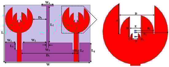
Figure 1.
Two-element MIMO antenna design and parameters.

Table 1.
Design parameters of the two-element MIMO antenna.
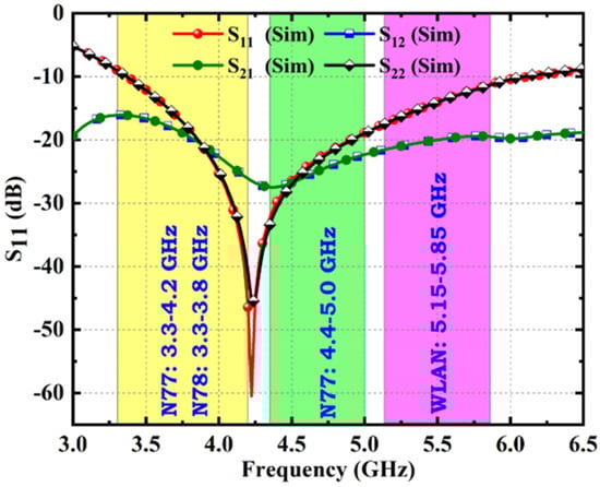
Figure 2.
S–parameters response.
The evolution of the two-element antenna is illustrated in Figure 3a–d. Antenna#1 is designed by two circular-shaped radiating elements of radius R1 mm each and a partial ground of size Lg × W mm2. Two slots are etched on the ground plane to achieve impedance matching in the working band. Then, a T-shaped stub (L2 × W3 and W3 × W4) is protruded to improve the isolation above 15 dB between the antenna ports. It is evident from Figure 3e that all antennas are resonating at 4.25 GHz with a frequency range of (3.3–6.0) GHz and S21 of more than 15 dB, but they differ in S11 values. Later, a rectangular slot of size A × D mm2 is etched from each circular patch element of Antenna#1 to form Antenna#2 as given in Figure 3b. As a result, S11 is improved from −35 dB to −42 dB. Antenna#3 is constructed by adding R2 mm radius circle with rectangular slot cut (B × E mm2) to the Antenna#2. The S11 is increased from −42 dB to −45 dB due to the inclusion of rectangular slotted circle. Finally, the proposed antenna denoted by Antenna#4 is formed by loading circle of radius R3 mm with rectangular slot of C × F mm2 to the Antenna#3 which results in further improvement in S11 from −45 dB to −62 dB. It is observed that Antenna#4 (proposed antenna) offers good impedance matching characteristics (S11 = −62 dB) and hence is adopted in this work. The S21 responses of all the evolution stages are depicted in Figure 4f.

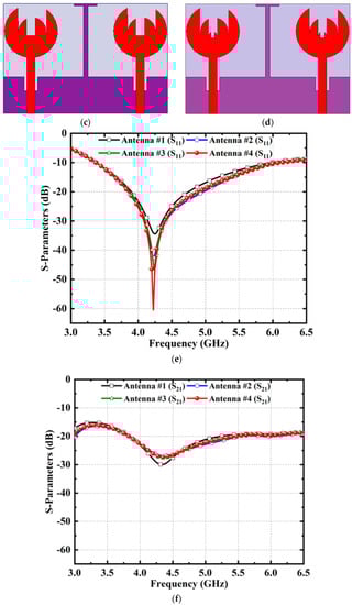
Figure 3.
(a–d): Two-element MIMO antenna evolution stages, (e) S11 response of all stages, and (f) S21 response of all stages.
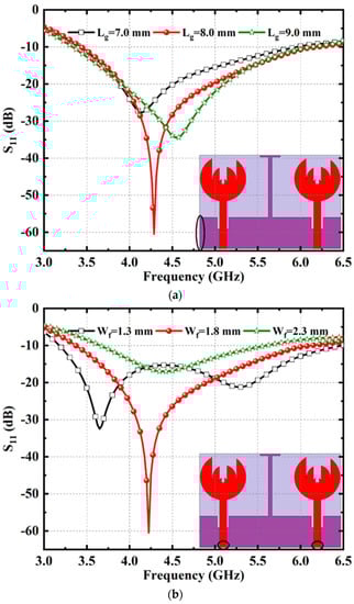

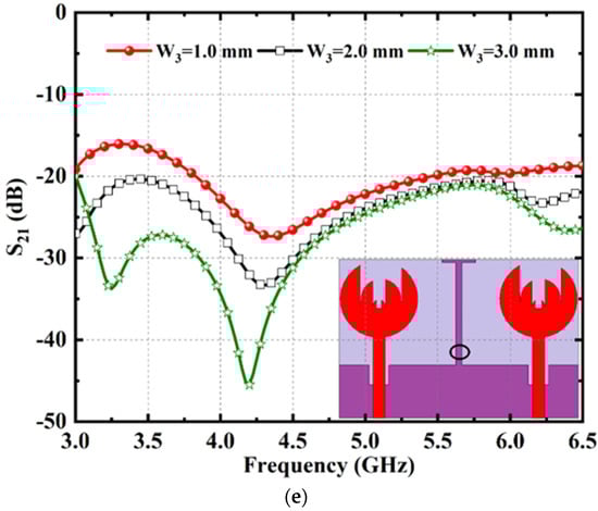
Figure 4.
Two–element MIMO antenna parametric analysis S–parameters response; (a) Lg; (b) Wf; (c) L1; (d) W3; and (e) W3 for isolation.
2.2. Evolution Two-Element MIMO Antenna Parametric Analysis
The parametric analysis is conducted on two-element MIMO antenna design parameters (such as Lg, Wf, L1, and W3) to better understand its behavior in terms of impedance matching (S11) and isolation (S21) characteristics, as depicted in Figure 4. It is noticed from Figure 4a that the lower cutoff frequency is around 3.3 to 3.4 GHz and higher cutoff frequency is about 6 GHz for all values of ground plane length Lg. However, when compared with Lg = 7 mm and 9 mm, Lg = 8 mm provides better S11 values and hence is selected as ground plane length in the proposed design. The effect of the feed width (Wf) on the impedance matching characteristics is presented in Figure 4b. It is found that as Wf changes from 1.3 to 2.3 mm, the lower cutoff frequency is shifting to right and upper cutoff frequency shifts to the left. Additionally, the S11 value for Wf = 1.3 mm and Wf = 2.3 mm is relatively less when compared with Wf = 1.8 mm. The required frequency band from 3.3 to 6.0 GHz with good S11 value is obtained for feed width Wf = 1.8 mm and hence selected in this proposed design. To improve the impedance characteristics (S11), two slots are etched from the ground plane under the feed line. The slot width denoted by L1 plays a crucial role in improving S11 as given in Figure 4c. It is identified that as L1 changes from 2 to 4 mm, the S11 parameter also changes. The required band from 3.3 to 6.0 GHz with good S11 value is achieved for slot width L1 of 3 mm and therefore chosen in this design.
Figure 4d represents the effect of T-shaped stub width W3 on the S11 and S21 (isolation parameter). It can be observed that the impedance matching (S11) is improved from −25 dB to 62 dB, but port isolation (S21) is decreased from 27 dB to 15 dB as the stub width W3 decreases from 3 to 1 mm. W3 = 3 mm offers high isolation, but poor impedance matching (S11 = −25 dB). However, W3 = 1 mm provides good impedance matching with acceptable port isolation and hence is selected in this design.
2.3. TCM Analysis
The results of the proposed two-element MIMO antenna are verified by performing theory of characteristic mode (TCM) analysis which is discussed in [31,32]. The parameters such as modal significance (MS) and characteristic angle are analyzed as a function of frequency. From the modal significance (MS) plot, a mode is said to be resonant mode when its modal significance value is in between 0.7 and 1.0. The modal significance (MS) as a function of frequency is depicted in Figure 5a. It can be found that modes such as Mode 2–5 and Mode 7 are the resonant modes since their value MS value is more than 0.7 and Mode 1 and Mode 6 are the non-resonant modes below 6 GHz. The characteristic angle vs. frequency plot is depicted in Figure 5b. A mode is said to be resonant mode when its value is around 180° as per the characteristic angle vs. frequency plot. It can be identified from Figure 5b that the Mode 2–5 and Mode 7 are the resonant modes as their values are around 180° and Mode 1 and Mode 6 are the non-resonant modes because their values are below 180°. The TCM analysis results agree well with the already proposed results. The equations of modal matrix, modal significance, and characteristic angle are represented in Equations (1)–(3) [33,34].

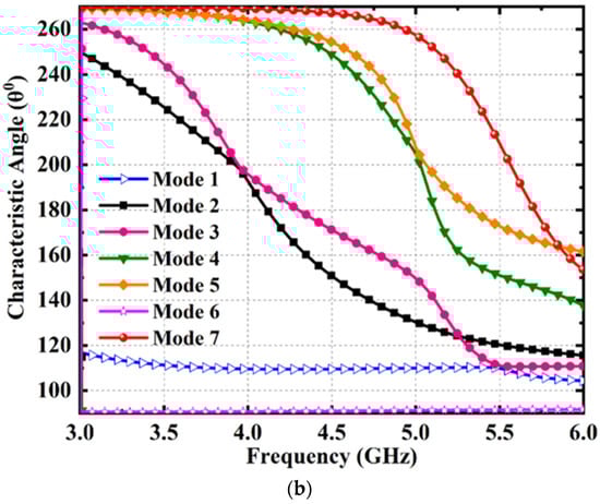
Figure 5.
Two–element MIMO antenna TCM analysis; (a) modal significance; and (b) characteristic angle.
The 3-D polar radiation characteristics of the two-element MIMO antenna at 3.5 GHz, 4 GHz, 4.5 GHz, and 5.5 GHz are presented in Figure 6. The proposed antenna offers steady boresight radiation patterns in the z-direction at all abovementioned frequencies, which makes it ideal for WLAN and 5 G sub-6 GHz applications.
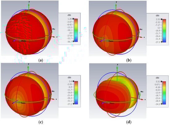
Figure 6.
Two–element MIMO antenna polar radiation pattern representation; (a) 3.5 GHz; (b) 4.0 GHz; (c) 4.5 GHz; and (d) 5.5 GHz.
2.4. Eight-Element MIMO Antenna Design and Analysis
The design of eight-element MIMO antenna of size 72 × 72 mm2 is depicted in Figure 7. The basic reason for extending two-element to eight-element is to enhance the capacity and data rate of the wireless devices. In the proposed design, all the two-element antennas are orthogonally spaced to enhance the isolation between the antenna ports. Furthermore, four triangle-shaped slots are etched at the center of the dielectric substrate to enhance the isolation above 15 dB. The impedance matching and isolation curves of the eight-element antenna are illustrated in Figure 8.
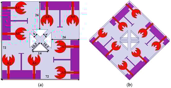
Figure 7.
Eight–element MIMO antenna; (a) design with parameter values and (b) isometric view.
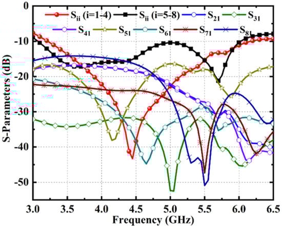
Figure 8.
Eight–element MIMO antenna S–parameters response.
The S–parameters (Sii, where i = 1 to 8) are drawn as two plots, namely Sii (i = 1–4) and Sii (i = 5–8), because the influence of adjacent elements on A1–A4 is different from that of A5-A8. Nevertheless, both plots satisfy the impedance matching requirements, as found from Figure 8. The S–parameter values such as S11, S22, S33, and S44 of the elements A1–A4 are the same and the S–parameters such as S55, S66, S77, and S88 of the elements A5–A8 are similar. However, the isolation parameters are different for different elements, as observed in Figure 8. The proposed eight-element MIMO antenna provides good impedance matching behavior with isolation of above 15 dB at all desired frequency bands.
2.5. Eight-Element MIMO Antenna Surface Current Distribution Analysis
The isolation parameter is also analyzed at resonant frequencies such as 3.5 GHz, 4 GHz, 4.5 GHz, and 5.5 GHz by using the surface current distribution when port-1 is excited, whereas other ports are terminated by 50-ohms load, as presented in Figure 9. As observed in Figure 9, without decoupling structure, the surface current of one element is entered into adjacent elements which degrade the radiation performance of the antenna. However, with T-shaped stubs and triangle-shaped slots, the surface currents are blocked and thus improve the isolation between the ports.

Figure 9.
(a–d) Eight–element MIMO antenna surface current distribution (SCD) in working band frequencies.
3. Results and Discussion
3.1. S-Parameters
The comparison of simulated and measured S-parameters (Sii, where i = 1 to 8) are plotted in Figure 10. It is identified from Figure 10 that the antenna operates from 3.3 GHz to 6 GHz covering four bands such as N77 (3.3–4.2 GHz), N78 (3.3–3.8 GHz), N79 (4.4–5.0 GHz), and WLAN (5.15–5.85 GHz) with good impedance matching properties. The simulated and measured findings are in good agreement; however, there is a small difference because of conducting, dielectric, and SMA connection losses as well as fabrication tolerances. Figure 11 illustrates the measured isolation parameters of the proposed antenna. The proposed antenna offers enhanced isolation of greater than 15 dB between the antenna ports. Figure 8 and Figure 11 show that, with a few minor exceptions, there is a good match between the values for simulated and measured isolation. Figure 12 depicts the fabricated prototype of eight-element MIMO antenna.
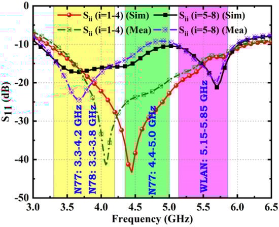
Figure 10.
S11 response (simulated and measured).
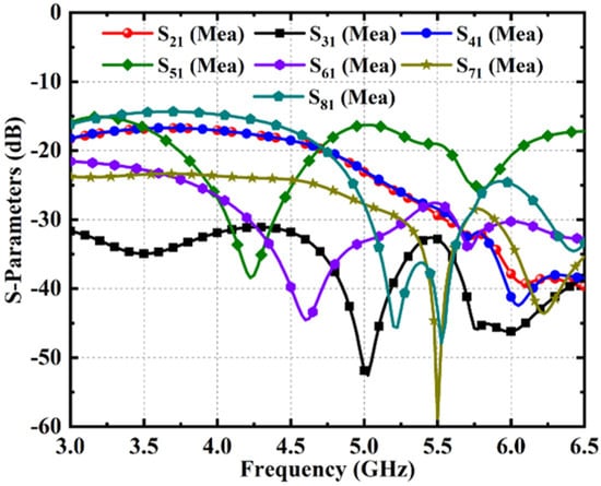
Figure 11.
Isolation response (measured).
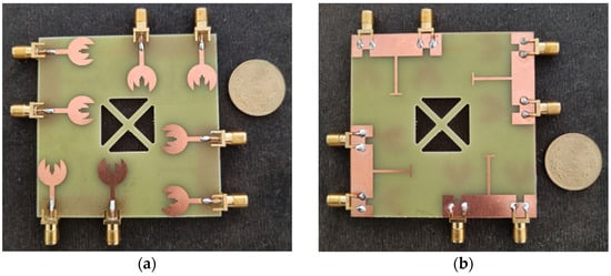
Figure 12.
Fabricated prototype: (a) front view and (b) rear view.
3.2. Radiation Characteristics
One of the most crucial characteristics of any antenna is its radiation performance. It specifies the nature of the fields, their strength, and the direction in which they are emitted. Figure 13 represents the two and eight-element MIMO antenna radiation efficiency and peak gain response curves. The proposed design achieves more than 95% radiation efficiency and greater than 2.5 dBi in the entire working band from 3.3–6.0 GHz. The simulated and measured E- and H-field radiation patterns at 3.5 GHz, 4 GHz, 4.5 GHz, and 5.5 GHz working bands of the proposed element MIMO antenna are depicted in Figure 14. It is noticed that E-fields are bi-directional and H-fields are omnidirectional patterns. Additionally, it can be found from 3-D polar patterns that the antenna has steady boresight radiation patterns at resonant bands that make it ideal for WLAN and 5G sub-6 GHz communication.
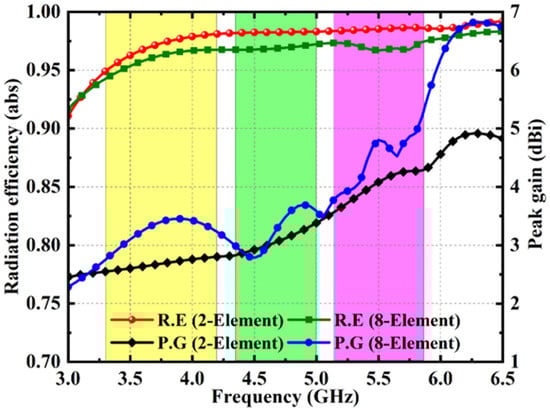
Figure 13.
Radiation efficiency and peak gain response.

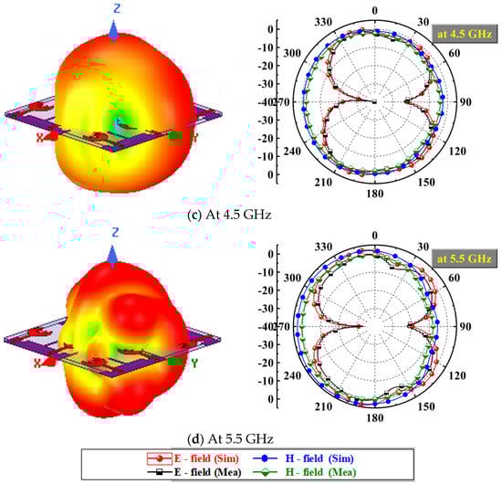
Figure 14.
(a–d) Radiation performance response in working band frequencies.
3.3. MIMO Diversity Characteristics
The envelop correlation coefficient (ECC) is a parameter used to analyze the MIMO antenna diversity [15]. Equations (4) and (5) for an N- and two-element system represent the ECC, which specifies how the channels are correlated. ECC if 0 means no correlation and 1 means very high correlation between the signals. ECC of less than 0.5 is the allowable value of ECC in practical applications. Figure 15a,b describes the simulated and measured ECC curves of the proposed eight-element MIMO antenna. It can be found that the proposed structure offers <0.005 throughout the band.
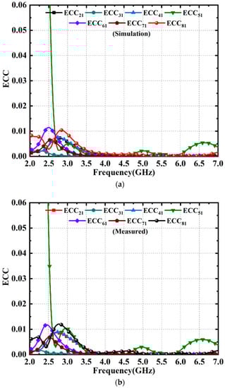
Figure 15.
ECC response: (a) simulation and (b) measured.
The diversity gain (DG) is a measure of the performance level of antenna diversity approaches [15,35]. Equation (6) can be used to evaluate the proposed MIMO antenna diversity performance. Figure 16 depicts the simulated and measured DG plots as a function of frequency where DG of approx. 10 dB is achieved across the working band.
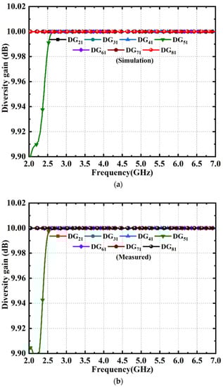
Figure 16.
DG response: (a) simulation and (b) measured.
Individual antenna S-parameter values are insufficient to analyze MIMO system performance when two or more antennas are placed next to each other. When both antenna elements are activated simultaneously, the radiation impacts the other antenna. Individual self-impedance and mutual impedance will vary. The S-parameters of individual MIMO antennas will not provide a perfect analysis. Total active reflection coefficient (TARC) is used to assess MIMO system behavior. TARC considers self and mutual impedance changes [36,37]. The following equation calculates the TARC for a two-port MIMO system (7). The proposed structure has TARC values below −10 dB across the spectrum Figure 17a,b.
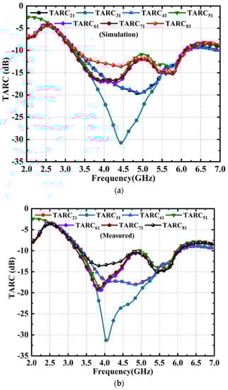
Figure 17.
TARC response: (a) simulated and (b) measured.
The channel capacity loss (CCL) defines how many bits are lost when two or more channels transmit signals at the same time. The mutual coupling between antenna elements is one of the main causes of capacity loss. Equations (8)–(10) are used to find the CCL in terms of S-parameters. The simulated and measured CCL plots are given in Figure 18. The proposed design delivers the CCL of <0.02 in the entire band.
where .
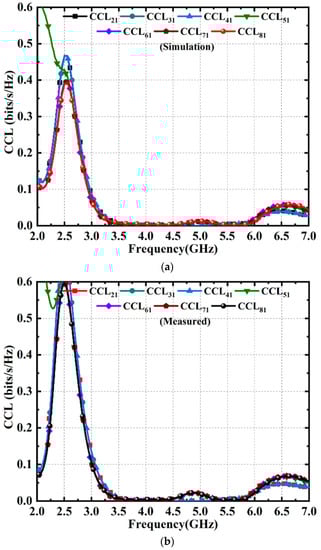
Figure 18.
CCL response: (a) simulated and (b) measured.
The mean effective gain (MEG) is a diversity performance indicating parameter that describes an antenna’s ability to receive electromagnetic signals in a multipath environment [38]. Equation (11) is used to calculate the MEG of the proposed antenna. Figure 19a,b illustrates the simulate and measured MEG plots, respectively. It is seen that the MEG of −3 dB is obtained in complete band from 3.3 to 6.0 GHz.
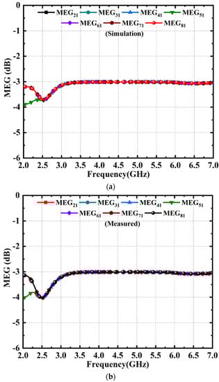
Figure 19.
MEG response: (a) simulated and (b) measured.
Table 2 shows the performance evaluation of the proposed MIMO antenna compared to others that have been described earlier. It is found that the proposed design offers better performance with respect to the impedance bandwidth, isolation, peak gain, ECC, DG, TARC, CCL, and MEG when compared with the existing antennas. Additionally, the size of the proposed eight-element antenna is small compared to existing eight-element antennas.
Table 2.
Performance comparison.
4. Conclusions
This communication proposes a novel compact fractal loaded two- and eight-element MIMO with high diversity for 5G Sub 6 GHz and WLAN applications. The presented antenna comprises fractal loaded circular patch elements and a partial ground with protruded T-shaped stub. Four triangle shaped slots in the substrate, along with a T-shaped stub on the ground, are employed to achieve good isolation in the complete band. The proposed antenna works at (3.3–6.0) GHz, covering the 5G sub-6GHz bands N77, N78, N79, and WLAN, with good impedance matching and high isolation characteristics. The antenna results are validated using the TCM analysis, and there is good agreement between the results. The antenna has a peak gain of >2.5 dBi, a radiation efficiency of above 95%, and steady boresight radiation patterns, making it well suited for 5G sub-6 GHz and WLAN communication.
Author Contributions
Conceptualization, B.K.K. and M.S.K.; methodology, C.R.J. and N.K.G.; software, T.A.; validation, T.A. and J.K.; formal analysis, B.K.K. and N.K.G.; investigation, M.S.K. and C.R.J.; resources, T.A.; data curation, B.K.K.; writing—original draft preparation, M.S.K. and C.R.J.; writing—review and editing, J.K.; visualization, N.K.G.; supervision, T.A.; project administration, C.R.J. and M.S.K.; funding acquisition J.K. All authors have read and agreed to the published version of the manuscript.
Funding
This research received no external funding.
Institutional Review Board Statement
Not applicable.
Informed Consent Statement
Not applicable.
Data Availability Statement
Not applicable.
Conflicts of Interest
The authors declare no conflict of interest.
References
- Andrews, J.G.; Buzzi, S.; Choi, W.; Hanley, S.V.; Lozano, A.; Soong, A.C.; Zhang, J.C. What will 5G be. IEEE J. Sel. Areas Commun. 2014, 32, 1065–1082. [Google Scholar] [CrossRef]
- Sim, C.-Y.; Dhasarathan, V.; Tran, T.K.; Kulkarni, J.; Garner, B.A.; Li, Y. Mutual Coupling Reduction in Dual-Band MIMO Antenna Using Parasitic Dollar-Shaped Structure for Modern Wireless Communication. IEEE Access 2023, 11, 5617–5628. [Google Scholar] [CrossRef]
- Ikram, M.; Sultan, K.; Lateef, M.F.; Alqadami, A.S. A Road towards 6G Communication—A Review of 5G Antennas, Arrays, and Wearable Devices. Electronics 2022, 11, 169. [Google Scholar] [CrossRef]
- An, Z.; He, M. A simple planar antenna for sub-6 GHz applications in 5G mobile terminals. Appl. Comput. Electromagn. Soc. J. (ACES) 2020, 35, 10–15. [Google Scholar]
- Kulkarni, J.; Sim, C.-Y.; Gangwar, R.K.; Anguera, J. Broadband and Compact Circularly Polarized MIMO Antenna With Concentric Rings and Oval Slots for 5G Application. IEEE Access 2022, 10, 29925–29936. [Google Scholar] [CrossRef]
- Azim, R.; Meaze, A.M.H.; Affandi, A.; Alam, M.; Aktar, R.; Mia, S.; Alam, T.; Samsuzzaman; Islam, M.T. A multi-slotted antenna for LTE/5G Sub-6 GHz wireless communication applications. Int. J. Microw. Wirel. Technol. 2020, 13, 486–496. [Google Scholar] [CrossRef]
- Foschini, G.; Gans, M. On Limits of Wireless Communications in a Fading Environment when Using Multiple Antennas. Wirel. Pers. Commun. 1998, 6, 311–335. [Google Scholar] [CrossRef]
- Tiwari, R.N.; Singh, P.; Pandey, S.; Anand, R.; Singh, D.K.; Kanaujia, B.K. Swastika shaped slot embedded two port dual frequency band MIMO antenna for wireless applications. Analog. Integr. Circuits Signal Process. 2021, 109, 103–113. [Google Scholar] [CrossRef]
- Ren, Z.; Zhao, A. Dual-Band MIMO Antenna With Compact Self-Decoupled Antenna Pairs for 5G Mobile Applications. IEEE Access 2019, 7, 82288–82296. [Google Scholar] [CrossRef]
- Kumar, M.; Nath, V. Design and development of triple-band compact ACS-fed MIMO antenna for 2.4/3.5/5 GHz WLAN/WiMAX applications. Analog. Integr. Circuits Signal Process. 2020, 103, 461–470. [Google Scholar] [CrossRef]
- Khan, J.; Ullah, S.; Tahir, F.A.; Tubbal, F.; Raad, R. A Sub-6 GHz MIMO Antenna Array for 5G Wireless Terminals. Electronics 2021, 10, 3062. [Google Scholar] [CrossRef]
- Chattha, H.T. 4-Port 2-Element MIMO Antenna for 5G Portable Applications. IEEE Access 2019, 7, 96516–96520. [Google Scholar] [CrossRef]
- Xu, Z.; Zhang, Q.; Guo, L. A Compact 5G Decoupling MIMO Antenna Based on Split-Ring Resonators. Int. J. Antennas Propag. 2019, 2019, 1–10. [Google Scholar] [CrossRef]
- Addepalli, T.; Anitha, V.R. Parametric Analysis of Compact UWB-MIMO Antenna with Improved Isolation Using Parasitic Reflectors and Protruded Ground Strips. Wirel. Pers. Commun. 2021, 123, 2209–2225. [Google Scholar] [CrossRef]
- Addepalli, T.; Anitha, V. A very compact and closely spaced circular shaped UWB MIMO antenna with improved isolation. AEU-Int. J. Electron. Commun. 2019, 114, 153016. [Google Scholar] [CrossRef]
- Biswas, R.; Nandi, A.; Parsha, M.K.; Basu, B. High Isolation, Wide Aperture Antenna Array Using Auxiliary Feeds and EBG Surface for 5G Communication. Arab. J. Sci. Eng. 2022, 47, 14935–14945. [Google Scholar] [CrossRef]
- Jetti, C.R.; Nandanavanam, V.R. Trident-shape strip loaded dual band-notched UWB MIMO antenna for portable device applications. AEU-Int. J. Electron. Commun. 2018, 83, 11–21. [Google Scholar] [CrossRef]
- Jetti, C.R.; Nandanavanam, V.R. A very compact mimo antenna with triple band-notch function for portable uwb systems. Prog. Electromagn. Res. C 2018, 82, 13–27. [Google Scholar] [CrossRef]
- Saxena, S.; Kanaujia, B.; Dwari, S.; Kumar, S.; Tiwari, R. MIMO antenna with built-in circular shaped isolator for sub-6 GHz 5G applications. Electron. Lett. 2018, 54, 478–480. [Google Scholar] [CrossRef]
- Chakraborty, S.; Rahman, M.A.; Hossain, A.; Mobashsher, A.T.; Nishiyama, E.; Toyoda, I. A 4-element MIMO antenna with orthogonal circular polarization for sub-6 GHz 5G cellular applications. SN Appl. Sci. 2020, 2, 1–13. [Google Scholar] [CrossRef]
- Sghaier, N.; Latrach, L. Design and analysis of wideband MIMO antenna arrays for 5G smartphone application. Int. J. Microw. Wirel. Technol. 2021, 14, 511–523. [Google Scholar] [CrossRef]
- Kulkarni, J.; Desai, A.; Sim, C.-Y.D. Wideband Four-Port MIMO antenna array with high isolation for future wireless systems. AEU-Int. J. Electron. Commun. 2020, 128, 153507. [Google Scholar] [CrossRef]
- Parchin, N.O.; Al-Yasir, Y.I.; Basherlou, H.J.; Abd-Alhameed, R.A.; Noras, J.M. Orthogonally dual-polarised MIMO antenna array with pattern diversity for use in 5G smartphones. IET Microw. Antennas Propag. 2020, 14, 457–467. [Google Scholar] [CrossRef]
- Rekha, S.; Ramson, S.R.J. Parasitically Isolated 4-element MIMO Antenna for 5G/WLAN Applications. Arab. J. Sci. Eng. 2022, 47, 14711–14720. [Google Scholar] [CrossRef]
- Aziz, H.S.; Naji, D.K. Compact dual-band mimo antenna system for lte smartphone applications. Prog. Electromagn. Res. C 2020, 102, 13–30. [Google Scholar] [CrossRef]
- Li, M.-Y.; Ban, Y.-L.; Xu, Z.-Q.; Wu, G.; Sim, C.-Y.-D.; Kang, K.; Yu, Z.-F. Eight-Port Orthogonally Dual-Polarized Antenna Array for 5G Smartphone Applications. IEEE Trans. Antennas Propag. 2016, 64, 3820–3830. [Google Scholar] [CrossRef]
- Li, M.Y.; Xu, Z.Q.; Ban, Y.L.; Sim, C.Y.D.; Yu, Z.F. Eight-port orthogonally dual-polarised MIMO antennas using loop structures for 5G smartphone. IET Microw. Antennas Propag. 2017, 11, 1810–1816. [Google Scholar] [CrossRef]
- Nosrati, M.; Daneshmand, M.; Virdee, B.S. Novel compact dual-narrow/wideband branch-line couplers using T-Shaped stepped-impedance-stub lines. Int. J. RF Microw. Comput. Eng. 2011, 21, 642–649. [Google Scholar] [CrossRef]
- Nosrati, M. An extremely miniaturized microstrip branch-line coupler. Microw. Opt. Technol. Lett. 2009, 51, 1403–1406. [Google Scholar] [CrossRef]
- Roshani, S.; Shahveisi, H. Mutual Coupling Reduction in Microstrip Patch Antenna Arrays Using Simple Microstrip Resonator. Wirel. Pers. Commun. 2022, 126, 1665–1677. [Google Scholar] [CrossRef]
- Harrington, R.; Mautz, J. Theory of characteristic modes for conducting bodies. IEEE Trans. Antennas Propag. 1971, 19, 622–628. [Google Scholar] [CrossRef]
- Babu, K.J.; Aldhaheri, R.W.; Sai, L.S.; Perli, B.R.; Addepalli, T.; Pasumarthi, S.R.; Kumar, B.K.; Devana VK, R. Design and modal analysis of dual-slot circular patch antenna for ultra-wideband applications. J. Optoelectron. Adv. Mater. 2022, 24, 355–364. [Google Scholar]
- Ghalib, A.; Sharawi, M.S. TCM Analysis of Defected Ground Structures for MIMO Antenna Designs in Mobile Terminals. IEEE Access 2017, 5, 19680–19692. [Google Scholar] [CrossRef]
- Addepalli, T.; Babu, K.J.; Beno, A.; Potti BM, K.; Sundari, D.T.; Devana, V.K.R. Characteristic mode analysis of two port semi-circular arc-shaped multiple-input-multiple-output antenna with high isolation for 5G sub-6 GHz and wireless local area network applications. Int. J. Commun. Syst. 2022, 22, e5257. [Google Scholar] [CrossRef]
- Addepalli, T.; Desai, A.; Elfergani, I.; Anveshkumar, N.; Kulkarni, J.; Zebiri, C.; Rodriguez, J.; Abd-Alhameed, R. 8-Port Semi-Circular Arc MIMO Antenna with an Inverted L-Strip Loaded Connected Ground for UWB Applications. Electronics 2021, 10, 1476. [Google Scholar] [CrossRef]
- Fritz-Andrade, E.; Jardon-Aguilar, H.; Tirado-Mendez, J.A. The correct application of total active reflection coefficient to evaluate MIMO antenna systems and its generalization to N ports. Int. J. RF Microw. Comput. Eng. 2019, 30, e22113. [Google Scholar] [CrossRef]
- Addepalli, T.; Vidyavathi, T.; Neelima, K.; Sharma, M.; Kumar, D. Asymmetrical fed Calendula flower-shaped four-port 5G-NR band (n77, n78, and n79) MIMO antenna with high diversity performance. Int. J. Microw. Wirel. Technol. 2022, 1–15. [Google Scholar] [CrossRef]
- Glazunov, A.A.; Molisch, A.; Tufvesson, F. Mean effective gain of antennas in a wireless channel. IET Microw. Antennas Propag. 2009, 3, 214–227. [Google Scholar] [CrossRef]
Disclaimer/Publisher’s Note: The statements, opinions and data contained in all publications are solely those of the individual author(s) and contributor(s) and not of MDPI and/or the editor(s). MDPI and/or the editor(s) disclaim responsibility for any injury to people or property resulting from any ideas, methods, instructions or products referred to in the content. |
© 2023 by the authors. Licensee MDPI, Basel, Switzerland. This article is an open access article distributed under the terms and conditions of the Creative Commons Attribution (CC BY) license (https://creativecommons.org/licenses/by/4.0/).