Article

Modeling and Stability Analysis Based on Internal Voltage Dynamics in Synchronverter

School of Automation, Hangzhou Dianzi University, Hangzhou 310018, China
*
Authors to whom correspondence should be addressed.
Electronics 2023, 12(3), 700; https://doi.org/10.3390/electronics12030700
Submission received: 30 December 2022 / Revised: 22 January 2023 / Accepted: 28 January 2023 / Published: 31 January 2023

Abstract

:
With the large-scale centralized penetration of renewable energy represented by wind turbine and photovoltaic power generation, the equivalent inertia and synchronous torque of traditional power grids have decreased, which is worsening the frequency dynamics and threatening the stability and reliability of power grids. Virtual synchronous generators (VSGs) are a type of grid-friendly inverter in microgrids (MGs) that mimic rotational synchronous generators (SGs) to maintain system stability with the increasing penetration of power electronic converters. In this paper, the stability analysis method of one type of VSG, synchronverter, is investigated based on internal voltage dynamics. The torque components affecting the stability mechanism of synchronizing, inertia, and damping torque is introduced, which offers a physical insight into transient stability and dynamic performance. Insufficiency in either damping or synchronizing torque would increase the unstable possibility. The characterization method of stability mechanisms can be illustrated by the phasor diagram of synchronverter internal voltage. Some cases under different disturbances which change the pattern of synchronizing and damping torque and in turn influence the internal voltage dynamics of synchronverters, are also discussed. In addition, an auxiliary correction control loop is proposed and added in the synchronverter control loop to enhance the robustness of the synchronverter against disturbances. The tunable coefficient of the correction loop is analyzed based on the internal voltage method. Simulation results verify the validity of the internal voltage stability method in synchronverters.

1. Introduction

The distributed energy resources connected to the electric power system (EPS) through voltage source converters (VSCs) are growing quickly [1,2,3]. The ratio of synchronous generators (SGs) in traditional power systems decreases and the equivalent inertia of power grids is reduced. As a result, the system stability will be jeopardized [4]. Moreover, the decrease of inertia will lead to a large frequency deviation and high rate of change of frequency (RoCoF) [5,6] under all kinds of disturbances to further damage the system. It is necessary to explore the control strategies that can equip the VSCs with inertia to overcome the adverse effects of low inertia.
Therefore, a variety of grid-forming control strategies for converters have been studied [7]. The controls of virtual synchronous generators (VSGs) have been investigated, where the mature synchronous generator technology is embedded in the controller core and accordingly these converters have the dynamic behavior of conventional SGs. This has become popular in recent research [8,9,10]. The characteristic comparison between VSG and SG is presented in Table 1. As shown, VSGs have a more flexible coefficient design than SGs, which provide more of a design margin for the controller in VSGs. One way to control VSGs is through the synchronverter [11], which can realize the astatic control of active and reactive power loops, making the system have the capacity for inertia provision and frequency and voltage regulations. More importantly, the electromagnetic characteristics of SGs are delicately inherited in synchronverters, including the dynamic behavior, which is more precise than other VSG types in portraying the electromagnetic dynamics performance. Moreover, phase-locked loop (PLL) control and the PLL-related instabilities in weak grid systems are avoided in synchronverters. In this case, the synchronverter is the competitive control for integrating RESs (Renewable Energy Sources), which are often located in remote areas and connected to a weak grid [11], and also applied to high-voltage DC (HVDC) transmission systems with VSCs [12]. Moreover, the weak grid will even lose more grid-strength with the large-scale access of power electronic devices, which will lead to the further reduction of inertia, damping, frequency/voltage regulation, and over-current capacity. The severe challenges to the safe and stable operation of power grids will be deeply imposed. In this situation, the advanced control technology with the active support ability of new energy exhibits important research value.
As one of the key stability problems of the power systems, angle stability can be divided into a small-signal and transient angle stability [8,9,10,11,12,13]. The small-signal analysis methods have been widely studied in VSG synchronverters by means of linear system theory such as eigenvalues and frequency analysis. The small-signal dynamics [14,15], the model establishment, and parameter design [16,17] of novel VSGs with optimized small-signal stability [18,19] are studied. Whereas, the analysis of transient angle stability is limited and needs to be further studied.
Firstly, the flexible and controllable parameters of the VSG body and power grid parameters will affect the transient stability. The virtual inertia and damping parameters of voltage-source VSGs, reactive droop coefficient, and line impedance parameters will affect the transient stability margin of the VSG itself. In this case, the research in [20] analyzed the damping relationship of damping coefficient D and inertial coefficient J in the second-order transfer function with power angle. However, this method could not demonstrate the dynamics under different disturbances. Secondly, the transient stability of VSGs can be improved by using appropriate transient control strategy. For example, analog, with the classical analysis method of a transient problem in the traditional power system, Equal Area Law, the transient stability of VSGs can be converted into the Lyapunov energy function method. The VSG power-angle stability would be improved through “reducing the acceleration area and increasing the deceleration area”, as was representatively shown in [21]. However, the Lyapunov energy function is not easy to obtain, and the prediction results always show some conservations. To improve the transient stability, some research studied the impact of the optimization of current limiting and the change of power reference or the limiting voltage on transient stability [22,23]. To simplify the analysis, the synchronizing coefficient is usually regarded as constant, then the equivalent synchronizing model was developed [24]. However, the above methods are rarely used in synchronverters, whether in transient parameter or transient control designs. As mentioned, synchronverters have more precise descriptions of electromagnetic dynamics and weak PLL-dependence compared to other types of VSGs, which greatly benefits the active support capability of new energy. Therefore, it is valuable to investigate the stability improvement of synchronverters.
Synchronverters could remove the PLL to create self-synchronization and power synchronization control, in which the voltage source converter feature would be maintained during the switch between islanded and grid-connected modes [25]. As a result, internal voltage dynamics can be used to demonstrate the essential characteristics of grid-connected VSGs whatever control strategies are applied. Some control methods based on the internal voltage stability of VSCs integrated into a weak grid are studied [26,27]. The effects of inner control on system stability based on internal voltage theory was revealed and a linearized model is derived in [13]. However, these discussions have not given further insight into the physical mechanism of VSGs. Furthermore, the analysis needs to be extended into transient analysis so that the dynamics behavior can be comprehensively described.
Based on the conventional synchronous machine theory, electromagnetic behavior is used to describe the dynamics with the timescale covering the inductor and the capacitor characteristic in SGs. Due to the simulation of SG external characteristics in synchronverters, the equivalent motion dynamics of the synchronous generator rotor can also be applied. How to use the analysis method of SG rotor motion in the synchronverter is an interesting topic. According to SG theory, two unstable conditions in synchronverters can be described: (1) the virtual rotor angle is continuously increased due to the lack of synchronizing torque; (2) the virtual rotor will swing with the increasing amplitude due to the insufficient supply of damping torque.
In other words, the torque variance after suffering disturbance can be decomposed into two individual components:
Δ T e = T s Δ δ + T D Δ ω
where Ts is the synchronous torque coefficient and TD is the damping torque coefficient.
The stability of the power system is dependent on these two components of every power converter. Without sufficient synchronous torque, the virtual power angel and the rotor angle will be in an unstable operation with the phenomena of aperiodic deviation. On the other hand, the system will be led to unstable oscillation without enough damping torque. In this sense, the concepts of damping torque and synchronizing torque can be adopted in the synchronverter as well. In this paper, inspired by the SG theory, the concept of synchronverter internal voltage is proposed to describe the physical properties of a synchronverter with grid-connected operation mode. To explore the physical meaning, synchronverter inertia, damping torque, and synchronizing torque for low-frequency oscillation description are explained. In addition, how these torques influence the internal voltage stability is also discussed. In addition, to improve the transient dynamics, an auxiliary correction control loop across active power loop (APL) and reactive power loop (RPL) are proposed, which brings the positive effect on synchronverter transient stability without affecting the steady-state performances.
Contributions of this paper are as follows:
  • Considering the similarity of electromagnetic dynamics between synchronverters and SGs, the analysis method of internal voltage is proposed. Concepts of inertia, damping, and synchronizing torque in a wide timescale are presented, as well as the operation mechanism and transient modeling. It is the first time to apply the internal voltage method in VSGs. Therefore, synchronverters can be explored from the perspective of physical insight and mechanism explanation.
  • The auxiliary correction control loop linking APL and RPL is proposed, which helps to enhance transient robustness against varied disturbances. The biggest advantage of the proposed loop is its easy implementation.
  • The model and stability analysis method of synchronverters under varied disturbances are presented. Moreover, the effectiveness of the proposed correction control loop in transient improvement is analyzed.
This paper is organized as follows. Section 2 introduces the preliminaries of synchronverters and describes the synchronverter control system. Section 3 presents the modeling and concept of internal voltage. The concepts of inertia, damping torque, and synchronizing torque in electromechanical timescales are explained as well. The auxiliary correction control loop is proposed to improve the transient performance and is introduced in Section 4. The model of synchronverters is established, the analysis under disturbances of different strength grids, and operating points is analyzed based on internal voltage theory. The impact of coefficients on the proposed correction loop is indicated as well. In Section 5, simulation results are presented, and the conclusion is drawn in Section 6.

2. Preliminaries

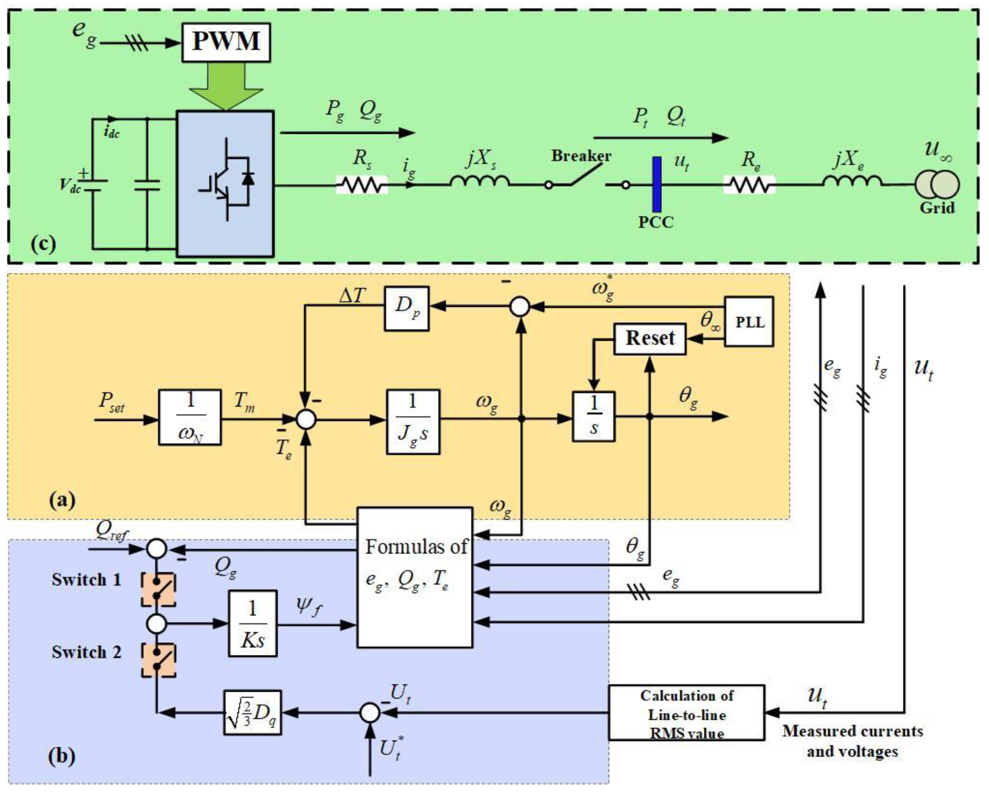
A synchronverter is a power electronic converter that mimics a conventional synchronous generator and acts as an interface for smart grid integration. As a result, distributed generation (DG) can easily take part in the frequency and voltage regulation and offer inertia and damping to the grid, as conventional synchronous generators do [11]. A synchronverter consists of a power part and a control part. The controller of a three-phase synchronverter, as shown in Figure 1, includes the mathematical model with a control core the same as a three-phase round-rotor synchronous machine. The back electromotive force eg in the mathematical model is passed through a Pulse- Width Modulation (PWM) generation block to generate PWM signals to drive the power switches. The currents flowing out of the inductors are treated as the stator current ig and feedback into the mathematical model. Two control loops, APL and RPL, are imbedded in the synchronverter controller.
Some assumptions are established: for a round rotor machine without damper windings, there are p pairs of poles per phase and no saturation effects in the iron core, and no neutral line among stator windings to form a star topology. As shown, the synchronverter has two control loops, which are APL (Figure 1a) and RPL (Figure 1b).
APL mimics SG rotor dynamics and sometimes it does not need PLL (here, PLL is drawn in Figure 1a for the grid-connected operation). The mechanical friction coefficient Dp is equivalent to the frequency droop coefficient, which saves the design of an extra frequency droop loop. This loop can regulate the synchronverter frequency/speed ω g and generate the phase angle θ g for eg. Pt and Qt are used to denote the active and reactive power injected into the grid from the PCC, respectively,
The electromechanics dynamics of the rotor is described as,
J g d ω d t = T m T e D p ( ω g ω g * )
where Jg is the moment of inertia of the rotational virtual rotor, Tm is the mechanical torque, and Te is the electromagnetic torque. Dp is damping coefficient. ω g is the rotating speed of the synchronverter-emulated SG, and the equation related to the virtual rotor angle is represented by θ g = 0 t ω g d t .
ω g * is its reference value. Te is obtained from the energy E stored in the machine magnetic field:
T e = p E θ m | i g , i f   constant = p M f i f i , s i n ˜ θ g = Ψ f i g T [ sin θ g , sin ( θ g 2 3 π ) , sin ( θ g + 2 3 π ) ] T
where M f i f = Ψ f denotes the excitation flux, and the mechanical torque is calculated by T m = P r e f ω N .
Dp is defined as Δ ω g / Δ T ( Δ ω g = ω g ω g * ), and it can be set for the torque to change 100% for a 1% frequency change, for example. The active torque Tm can be obtained from the reference active power Pref by dividing it with the nominal mechanical speed ω g * [11].
In RPL, as shown in Figure 1b, the synchronverter output active power Qg or line-to-line RMS value of the point of common coupling (PCC) terminal voltage ut can be controlled by regulating the excitation flux Ψ f . The dynamics of Ψ f are descried as
K d Ψ f d t = S 1 ( Q r e f Q g ) + S 2 2 3 D q ( U t * U t )
where Qref is the reference reactive power, which is equal to the nominal power here, and U t * and U t are the line-to-line RMS value of reference and output terminal voltage, respectively. The difference between U t * and t U t is amplified with the voltage droop coefficient Dq before adding to the difference between Qref and the reactive power Qg. The resulting signal is then fed into an integrator with a gain of 1/K to generate Ψ f . Here K is dual to the inertia Jg. The time constant τ v of the voltage loop is
τ v = K ω g D q K ω g * D q
In addition, there is, Dq = ΔQg/ΔUt. The active and reactive power are, respectively,
P g = ω g Ψ f i g T [ sin θ g , sin ( θ g 2 3 π ) , sin ( θ g + 2 3 π ) ] T
Q g = ω g Ψ f i g T [ cos θ g , cos ( θ g 2 3 π ) , cos ( θ g + 2 3 π ) ] T
As shown in Figure 1c, the synchronverter is connected to the grid with the voltage u . The inner voltage eg of a synchronverter and its RMS value Eg are addressed as,
e g = ω g Ψ f [ sin θ g , sin ( θ g 2 3 π ) , sin ( θ g + 2 3 π ) ] T
E g = 3 2 ω g Ψ f
The interface of a grid with a synchronverter needs to pass the output L-type filter with equivalent resistance Rs and reactance Xs. The PCC is connected to the grid via transmission line with resistance Re and reactance Xe. To simplify the analysis, the system is inductive dominant, which means Xe > > Re. Assuming that the phase angle of grid is θ , an angle difference between the grid and synchronverter inner voltage will exist and is represented by
d θ g d t = d θ g d t d θ d t = ω g ω
where ω g = 2 π f is the angular speed of the grid voltage, and θ is the phase angle of u .
There is,
P t P g = T e ω N = ω N 3 2 Ψ f U sin θ X e + X s
Q t = X e ( X s X e ) 2 E g 2 X s ( X s X e ) 2 U 2 + X s X e ( X s X e ) 2 E g U cos ( θ g θ )
Note that U is the line-to-line RMS value of u .
According to the main circuit shown in Figure 1, the relationship equation is obtained as follows:
P g = U g U X e + X s sin ( θ g θ )
Then,
sin ( θ g θ ) = P g X e + X s U g U

3. Internal Voltage Analysis of Synchronverters

In a sense, synchronverters belong to the VSC category, which is inhered from VSC inner voltage characteristics but exhibits some differences.

3.1. Internal Voltage in Synchronverters

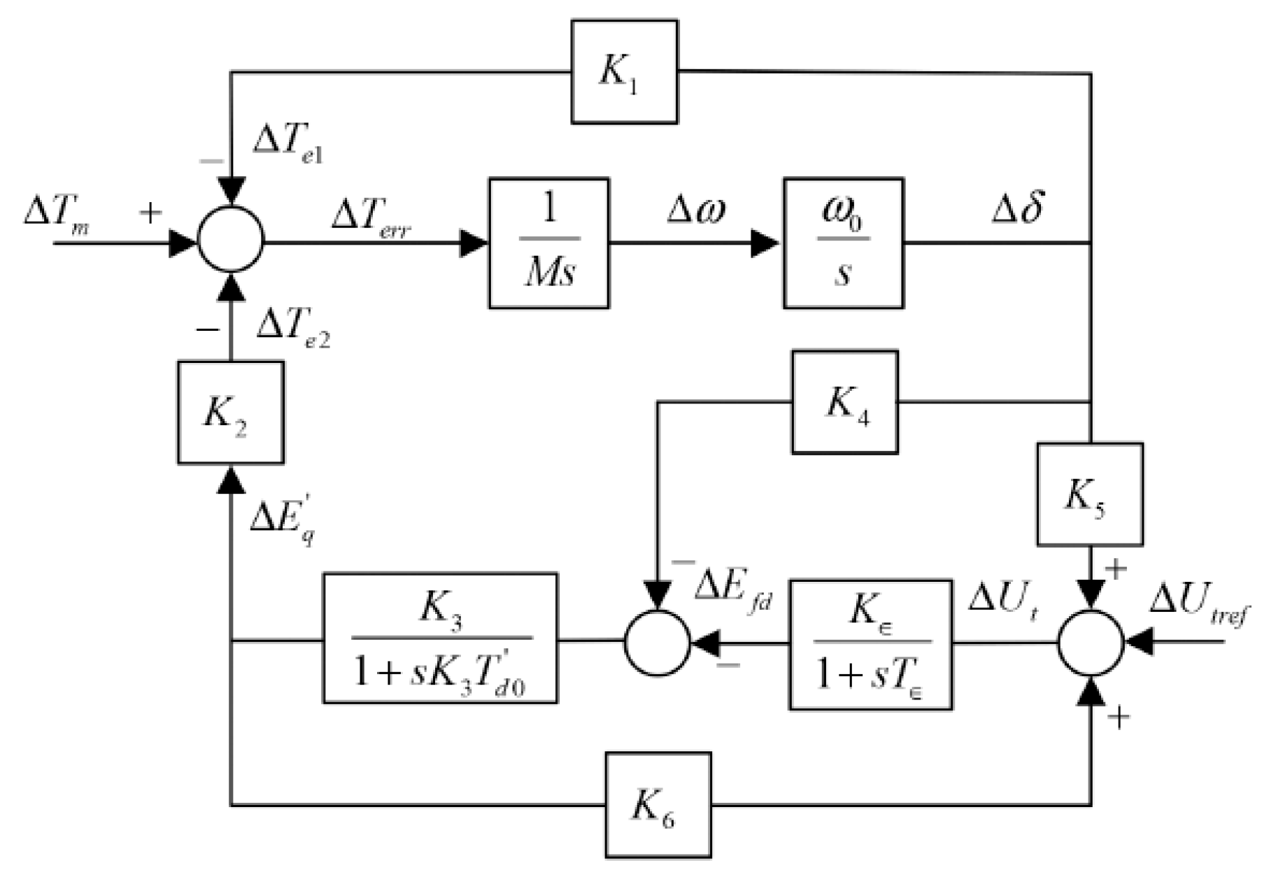
Figure 2 is the typical small-signal model of a single synchronous generator (SG) supplying an infinite bus system. In the torque-angle loop, the feedback electric torque ΔTe is composed of two components, which can be expressed as:
ΔTe = K1Δδ + K2ΔEq
If the circuit resistance is neglected, the coefficients K1K4 in Figure 2 are expressed as [28]:
K1 = E′qUg0cosδ0/(Xg + X′d)
K2 = Ug0sinδ0/(Xg + X′d)
K3 = (Xg + X′d)/(Xg + Xd)
K4 = (XdX′d)/(Xg + X′d)Ug0sinδ0
From the point of view of SG, the synchronverter has similar inner voltage characteristics theoretically. Following the conventional SG model, the synchronverter inner voltage can be defined as eg, which is located before the filter inductance. The angle θ g = θ g θ is regarded as the power-angle. In a synchronverter, θ g = θ g θ can be obtained through virtual mechanical dynamics, i.e., swing function.
Since U is the line-to-line RMS value of u, according to the phase diagram shown in Figure 3a, the RMS value of terminal voltage ut is,
U t = X e 2 ( X e + X s ) 2 E g 2 + 2 X e X s ( X e + X s ) 2 E g U cos θ g + X s 2 ( X e + X s ) 2 U 2
As for the transient dynamics of a synchronverter, control design could be implemented in different timescales.

3.2. Small-Signal Modeling of Synchronverter Internal Voltage

Some assumptions are established before the analysis of synchronverter small-signal modeling and are demonstrated as follows:
  • Control system dynamics in a fast current inner-loop timescale are neglected;
  • The effect of the AC capacitor is not considered;
  • The active power input Pin is constant.
As stated, the LCL filter is represented by the fundamental frequency impedance and the high-frequency component is shunted.
As shown in Figure 1c, the grid interface of a synchronverter is closely linked with filter impedance and terminal impedance, as follows:
e g U t X s = U t U X e
Equation (21) is organized by,
U t = X e X e + X s e g + X s X e + X s U
Equation (22) is written as,
U t = X e cos ( θ g θ t ) X e + X s E g + X s cos θ t X e + X s U
0 = X e sin ( θ g θ t ) X e + X s E g X s sin θ t X e + X s U
Equation (1) is rewritten by combining (2):
J g d ω d t = T m 3 2 Ψ f U X s + X e sin ( θ g θ ) D p ( ω g ω g * )
Linearizing Equations (23) and (24), results in the following:
Δ P e = E g 0 U 0 cos θ g 0 X e + X s Δ θ g + U 0 sin θ g 0 X e + X s Δ E g
Δ U t = E g 0 sin ( θ g 0 θ t 0 ) X e X e + X s Δ θ g + cos ( θ g 0 θ t 0 ) X e X e + X s Δ E g
Based on equation (7), the linearized result is written:
Δ Q g = 2 X e E g 0 + ( X s X e ) U 0 cos ( θ g 0 θ 0 ) ( X e + X s ) 2 Δ E g ( X s X e ) E g 0 U 0 sin ( θ g 0 θ 0 ) ( X e + X s ) 2 Δ θ g
In addition, linearization of the swing function (2) is obtained as follows:
Δ T m = J q Δ ω g s + 3 2 U 0 X s + X e sin ( θ g 0 θ 0 ) Δ Ψ f + 3 2 Ψ f 0 X s + X e U 0 cos ( θ g 0 θ 0 ) Δ θ g + D p Δ ω g
As for the reactive power loop, the linearized function is represented by
K Δ Ψ f s = [ 2 X e E g 0 + ( X s X e ) U 0 cos ( θ g 0 θ 0 ) ( X s + X e ) 2 + 2 3 D q X e cos ( θ g 0 θ t 0 ) X s + X e ] Δ E g + [ ( X s X e ) E g 0 U 0 sin ( θ g 0 θ 0 ) ( X s + X e ) 2 + 2 3 D q X e E g 0 sin ( θ g 0 θ t 0 ) X s + X e ] Δ θ g

3.3. Description of Inertia, Damping, and Synchronizing Torque

Synchronverters have some similar features with traditional synchronous generators. In this sense, the concepts of inertia, damping, and synchronizing torque can also be introduced in synchronverter analysis. Since the synchronverter is built by power electronic converters, the concepts of three different torque still exist during the operation.
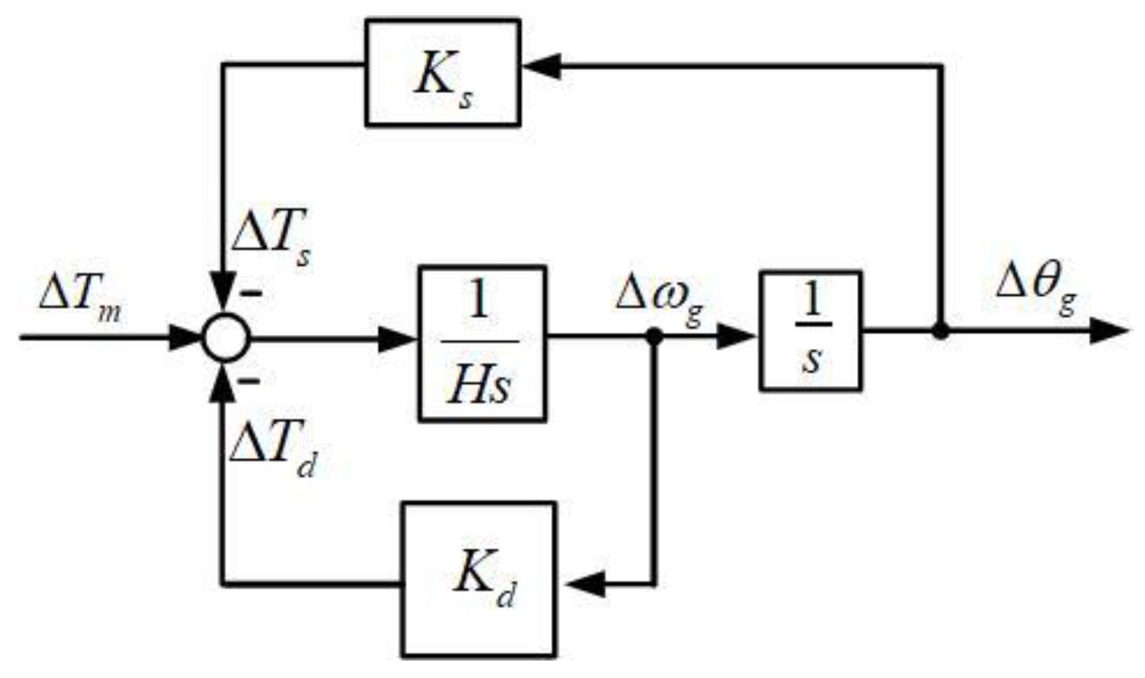
The electromagnetic torque variation Δ T e is divided into two components, one is Δ T d and the other is Δ T s . Δ T d is used to describe damping torque in proportion to rotate speed Δ ω g of the internal voltage, and Δ T s represents synchronizing torque which is in proportion to phase Δ θ g . The equation characterizing the torque variation is addressed as follows:
Δ T m = H Δ ω g s + K s Δ ω g s + K d Δ ω g
Δ T d = K d Δ ω g
Δ T s = K s Δ ω g s
where
H = J q
K d = D p
K s = 3 2 Ψ f 0 X s + X e U 0 cos ( θ g 0 θ 0 )
H is the inertia coefficient of the synchronverter, Kd represents the damping torque coefficient, and Ks is the synchronizing torque coefficient.
Synchronverter damping torque and synchronizing torque are the main factors to keep systems stable and secure. As shown in Figure 4, the small disturbance coming from the grid or load would produce variant torque, which is converted into variant synchronizing and damping torque. Due to the inheritance of a synchronous generator, the damping torque is directly proportional to the virtual damping coefficient Dp, whereas synchronizing torque is affected by more factors. Synchronverters exchange damping torque with the grid, instead of consuming it through resistance, which is helpful to suppress oscillation of the rotation speed in the internal voltage. Synchronizing torque is applied to restrain the oscillation of the internal voltage phase, which is beneficial for the synchronization between the synchronverter and grid.
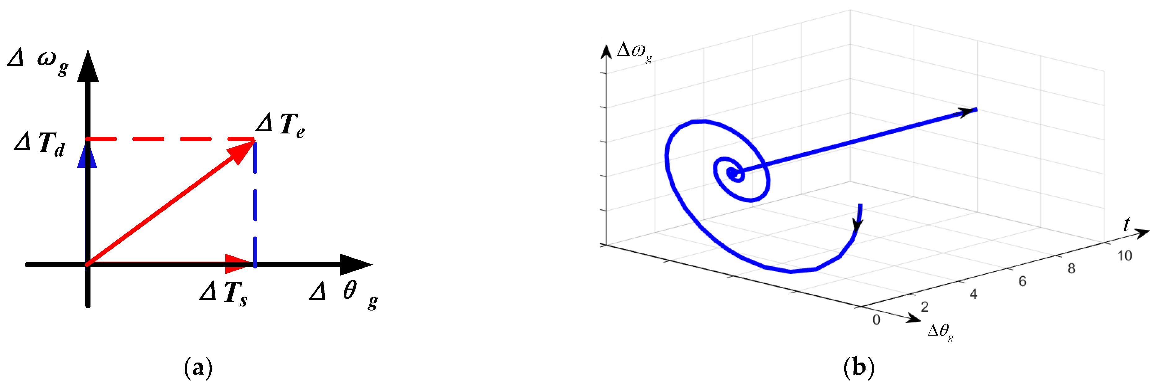
To investigate the impact of damping torque and synchronizing torque on the system stability in the synchronverter internal voltage, the small disturbance is forced and the movement trajectory of rotational phase and angular frequency variation is drawn, which is illustrated in Figure 5 and built in the Δ θ g - Δ ω g reference frame. Although the synchronverter was enforced by disturbance, the phase and rotational speed variance of internal voltage will finally reach zero and the system will become stable. A phasor diagram of damping and synchronizing torque is shown in Figure 5a, it is pointed out that the synchronizing torque is in phase with a small variation of synchronverter phase Δ θ g . Whereas, the damping torque is in phase with the variation of synchronverter internal voltage rotational speed Δ ω g as illustrated in Equations (31)–(33). The synthesized electromagnetic torque variation Δ T e is situated in the first quadrant under the damping and synchronizing torque actions, and thereby the small disturbance is restrained and even eliminated. Overall, the damping torque can be used to damp the oscillation of synchronverter rotational speed of internal voltage, and the synchronizing torque is contributed to damp the oscillation of internal voltage phase.
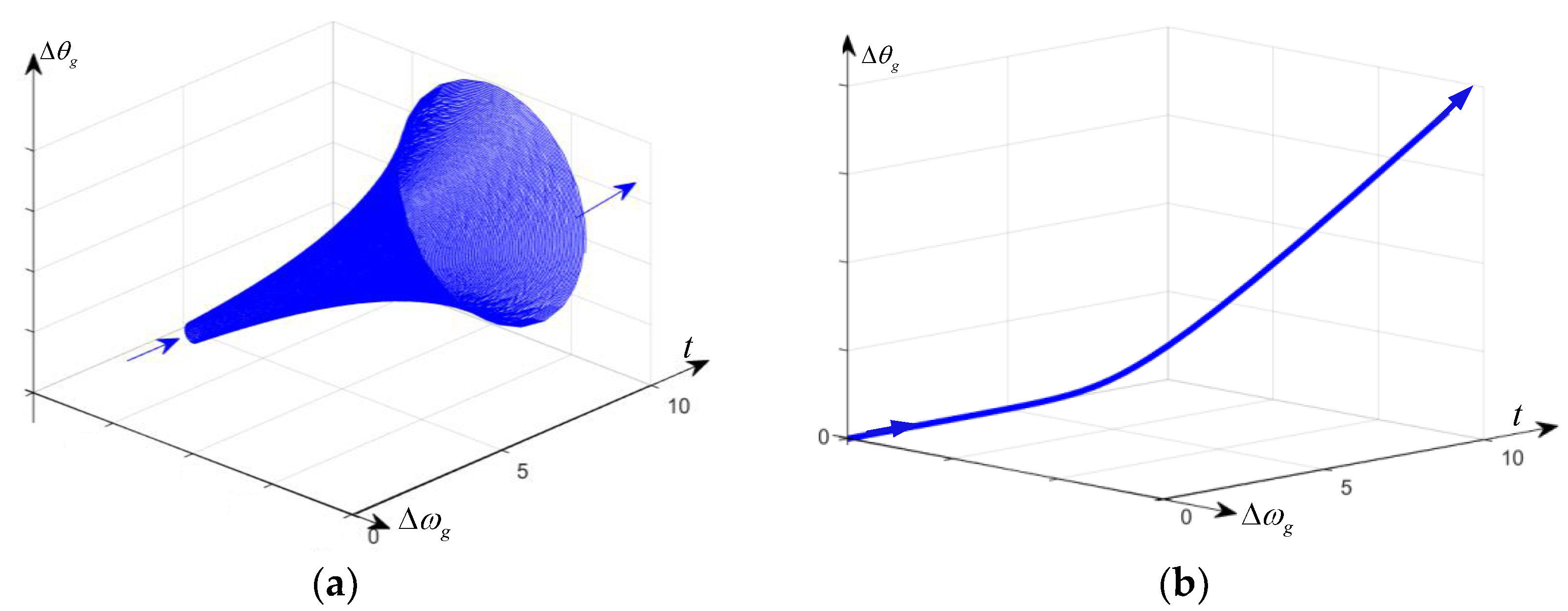
To investigate the impacts of the two torques on system stability, two cases are investigated, and the response results are illustrated in Figure 6. It is clearly shown in Figure 6a that the diverging oscillation of internal voltage occurs when damping torque is negative. On the other hand, the negative synchronizing torque (the damping power is still positive) will result in the synchronverter instability as shown in Figure 6b. It is noteworthy that there is synchronizing torque to regulate by means of tuning Ks in synchronverter, which indicates there is a possibility of PLL-less design that different with other VSC (voltage source converter) [29]. Therefore, the internal voltage method provides an alternative for the mechanism-based analysis of the synchronverter.
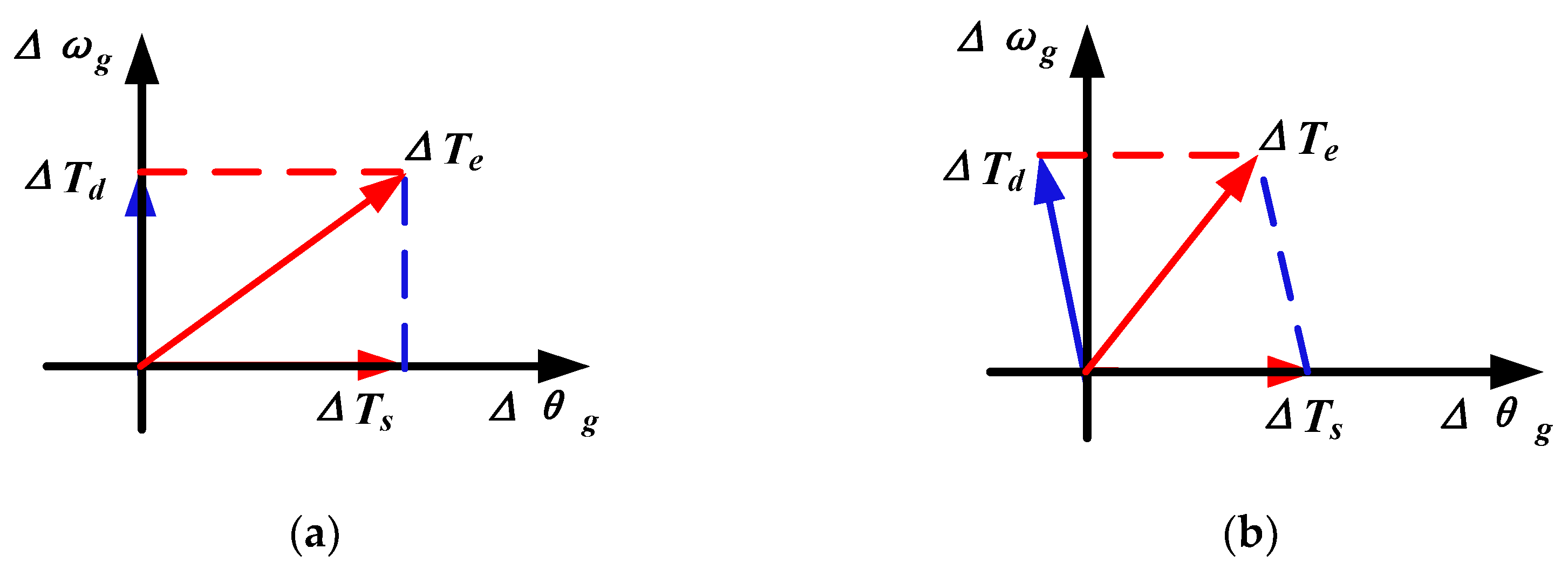
The phasor diagram for demonstrating the leading effect of damping torque is illustrated in Figure 7. Due to the leading effect, damping torque variant Δ T d is in the second quadrant. Compared with the normal condition, the synthesizing vectors Δ T e = Δ T s + Δ T d are more likely to step into the second quadrant to lose system stability when damping torque is reduced.

3.4. Proposed Synchronverter Controller Design

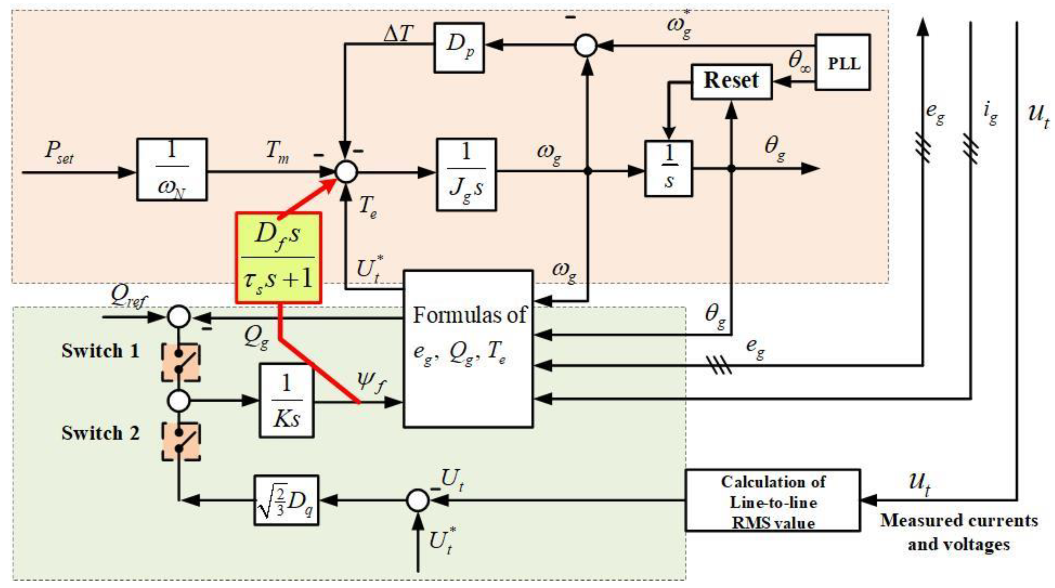
When disturbances such grid dip occur, the internal voltage of VSC in RPL is likely to oscillate and in turn deteriorate the APL stability. Since the droop coefficients in APL and RPL in synchronverters re hard to change due to the influence of steady-state droop characteristics, designing another auxiliary control loop would be a desirable method to improve the transient stability. In this paper, an auxiliary correction loop is proposed and added between APL and RPL, which is addressed by the red line in Figure 8; the power interface with the grid is the same as Figure 1 and neglected here. The input of the correction control loop is Ψf, and its output is obtained by the high-pass filtering of Ψf, where Df is a tuneable parameter. The high-pass filter D f s τ s s + 1 can relieve the transient dynamics caused by the disturbances without changing the inertial characteristics in APL and RPL.

4. Stability Analysis Based on Internal Voltage Dynamics

4.1. A Small-Signal Model of a Synchronverter with an Auxiliary Correction Loop

As discussed, the system stability of synchronverters can be analyzed through studying responses of internal voltage, which is highly affected by damping and synchronizing torque. However, the Equations of (31)–(33) are obtained without considering the APL. In this section, the synchronverter internal voltage is thoroughly studied by exploring damping and synchronizing torque including both APL and RPL.
Combining Equations of (31)–(36), is the following is obtained:
Δ T m = J q Δ ω g s + D p Δ ω g + 3 2 Ψ f 0 ( X s + X e ) 3 K s [ ψ f 0 cos ( θ g 0 θ 0 ) ( X e + X s ) 2 K s + U 0 sin 2 ( θ g 0 θ 0 ) E g 0 ( X s X e ) + D q E g 0 sin ( θ g 0 θ 0 ) sin ( θ g 0 θ t 0 ) X e ( X e + X s ) ] Δ θ g = J q Δ ω g s + G d ( s ) Δ ω g + G s ( t ) Δ θ g
There are three components in Equation (37): inertia, damping torque, and synchronizing torque in the view of internal voltage stability. Gs(s) is used to describe the gain of variance of internal voltage angle with respect to synchronizing torque as shown as follows, without considering the phase angle variance of grid Δ θ :
Δ T m G ( s ) Δ ω = G h ( s ) Δ ω g s + G d ( s ) Δ ω g + G s ( s ) Δ ω g s
where
G h ( s ) = J g + τ s D p τ s s + 1
G d ( s ) = τ s J g X t s 2 + D p X t + D f 3 2 U cos ( θ g 0 θ 0 ) ( τ s s + 1 ) X t = Δ T d Δ T m
G s ( s ) = ω N ψ f 0 3 2 U cos ( θ g 0 θ 0 ) ( τ s s + 1 ) X t = Δ T s Δ T m
G ( s ) = J g s + D p
When a synchronverter is working in grid-connected mode, the variance of mechanics torque is affected by the grid frequency fluctuation Δ ω , which further changes the damping and synchronizing torque. According to the expressions of (39)–(42), the variances of damping and synchronizing torque all have the angle with their coordinate Δ ω g and Δ θ g . The synthesized torque can be designed in the first quadrant to guarantee the system stability.
To investigate the impact on the damping and synchronizing torques, the synchronverter small-signal model is built in Section 4. The transfer function G1(s) is defined by
G 1 ( s ) = Δ T e 1 Δ ω g
G1(s) is influenced by control parameters of the synchronverter, operating point, and grid strength. The expression of Gs(s) is strictly synchronized with the small variation of Δ θ g and is regarded as the dominant factor to keep system synchronize with the grid. In synchronizing torque function, Δ T e 1 should be designed in a positive direction of Δ θ g , which is located in the first/fourth quadrant. The damping torque should be in close phase with the direction of Δ θ g to damp the oscillation of internal voltage. G1(s) is used to reflect the dynamics of damping torque. Gh(s) is the equivalent inertia composed of time constant tf, inertia Jg, and damping coefficient Dp. Gd(s) is the damping gain.

4.2. Analysis of Internal Voltage Stability

The dynamics of phase and magnitude in terminal voltage are sensitive to the output power, the disturbances such as voltage dip likely exaggerate this sensibility. In turn, some minor disturbances reflected in internal voltage would dramatically change the output power. A strong coupling between internal voltage and output power is built. The damping torque is affected by the factors related to the rotational angular speed of internal voltage, which can be analyzed through the expression of Gd(s). There is a leading effect between damping torque and rotational speed variance Δ ω g of internal voltage. As a result, the synthesized torque would likely fall in the second quadrant and the system would be unstable with a negative damping component, as shown in Figure 7. Since there is no PLL provided in the synchronverter, and no lagging regulator towards variance of internal voltage phase is adopted, the phase-synchronization is then realized. The internal voltage stability is accordingly converted into the damping torque analysis, which is why the transfer function of Gd(s) needs to be specifically discussed. The synthesized torque contributed by synchronizing and damping torque is also defined. To illustrate the detailed impact of these two torques, the phasor diagram is drawn in the Δ θ g and Δ ω g coordinates. Both damping and synchronizing components should be positive in ideal situations based on the phasor diagram. Due to the leading effect of Gd(s), a small negative synchronizing torque component exists. It is necessary to evaluate the overall synchronizing torque.
Figure 7b presents the results based on the small-signal model of the synchronverter. There is a leading angle θ 1 between the damping torque and rotational speed variance Δ ω g , as analyzed by phase-angle characteristics via the Bode diagram, which brings the decrease in damping torque and subsequently jeopardizes the system stability. Based on stability criterion, the internal voltage can maintain stability with positive damping and synchronizing torque.
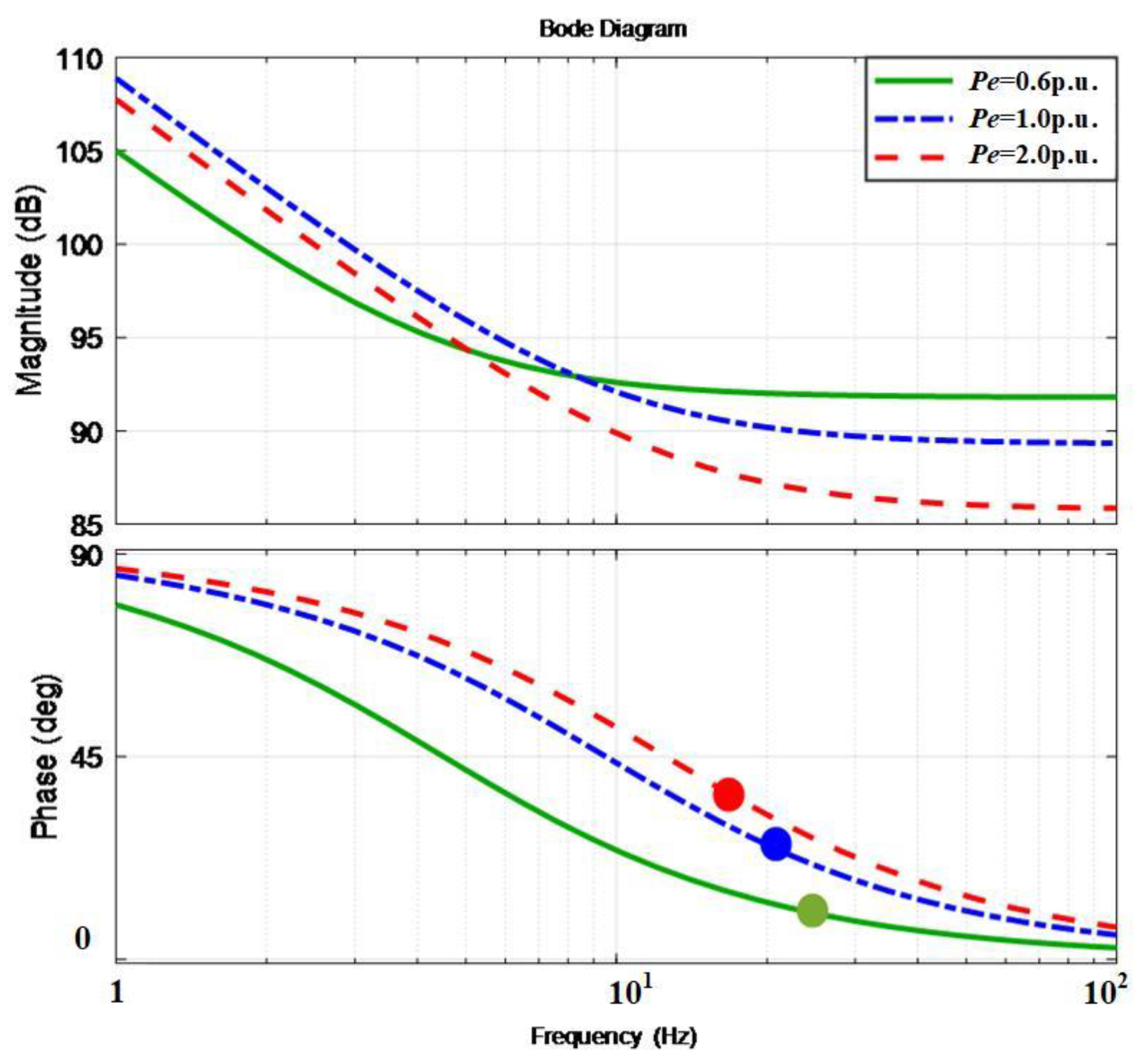
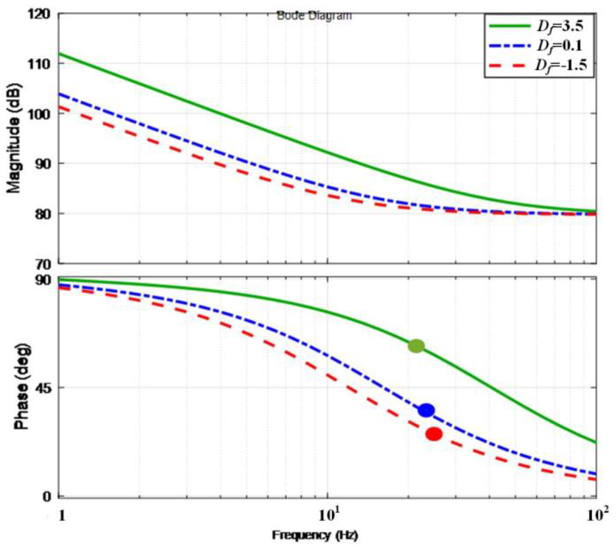
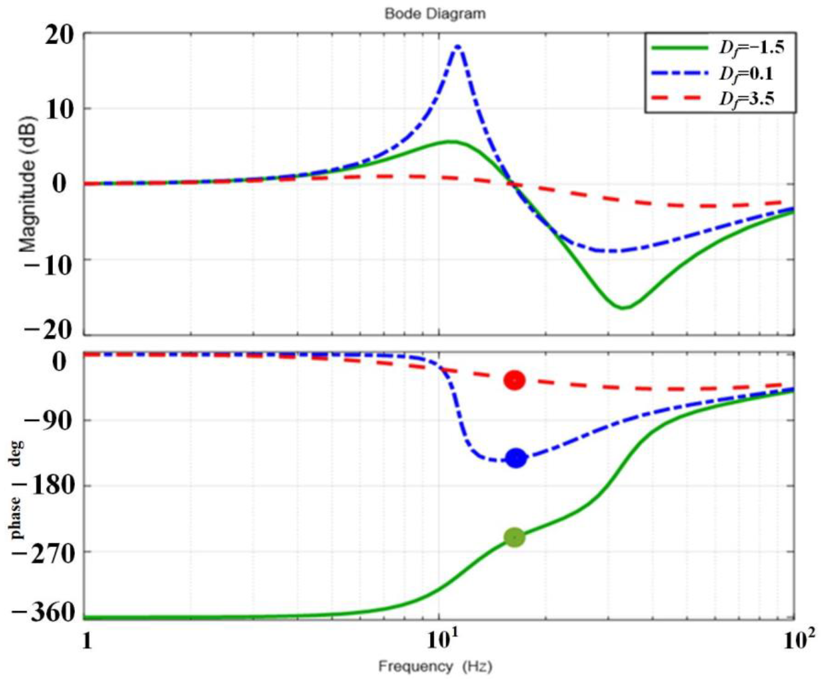
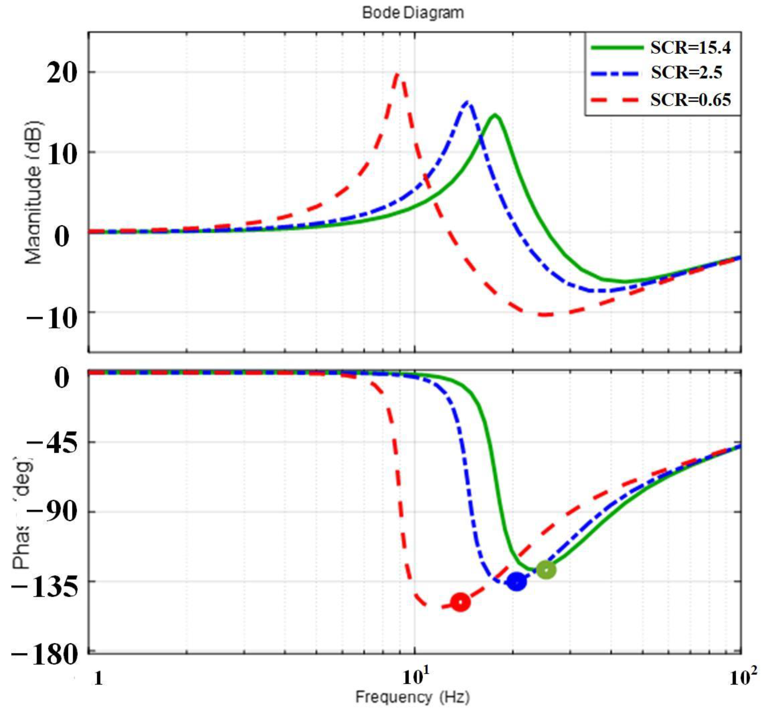
The quantized influencing analysis can be viewed by observing Gd(s)’s phase characteristics at the oscillation frequency obtained from the Bode diagram. The oscillation frequency is regarded as the frequency dominated by the main pole in the synchronverter model. To examine the internal voltage stability from the perspective of damping torque, the phase margin in G1(s) is a useful tool. The open-loop bode diagrams of G1(s) are presented in Figure 9, Figure 10 and Figure 11 with variant operation points, Df in auxiliary correction loop and grid strengths. The grid strengths are defined by the concepts of SCR (short circuit ratio). From Figure 9, it is obtained that the phase angle between Te1 and Δ ω g reference frames becomes larger when the active power output is from 0.6 p.u. to 1.0 p.u. and 2 p.u. (per-unit value of rated power). The output active power is lower, the angle is approaching zero. In fact, since the damping components are all positive in these three cases, the disturbance can be fed back over the decreased rotational speed of the internal voltage. Whereas the synchronizing components of Te1 projected in Δ θ g reference frame are negative, a potential risk of inducing the system in an unstable state exists. The proposed correction loop can regulate the damping and dynamics performance of APL. In this sense, the tunable coefficient Df acts as the function of dynamics and damping modification. To describe the physical mechanism, G1(s) gives the bode results with three different Df. The angle is very large when Df = −1.5, that means the absolute value of negative synchronizing torque, which is projected in the Δ θ g reference frame, will be larger than the case with Df = 0.1 and 3.5. It implies that the negative stability effect is comparatively slight when Df is positive. The results are shown in Figure 10. In the third case, the different grid strengths that are reflected by SCR are investigated and the results can be observed in Figure 11. The phase of G1(s) at the dominated frequency becomes smaller since SCR is changed from a stiff grid (SCR = 15.4) to a moderate grid (SCR = 2.5) and to a weak grid (SCR = 0.65). Although the absolute value of negative synchronizing torque derived from Δ T d grows larger when the grid strength becomes weaker, the synchronverter is capable of providing more support on synchronization torque against disturbance from the weak grid.
In order to assess whether the results based on internal voltage stability are valid, the Bode diagram with the open-loop transfer function G2(s) is addressed. G2(s) is defined as
G 2 ( s ) = Δ T e Δ T m
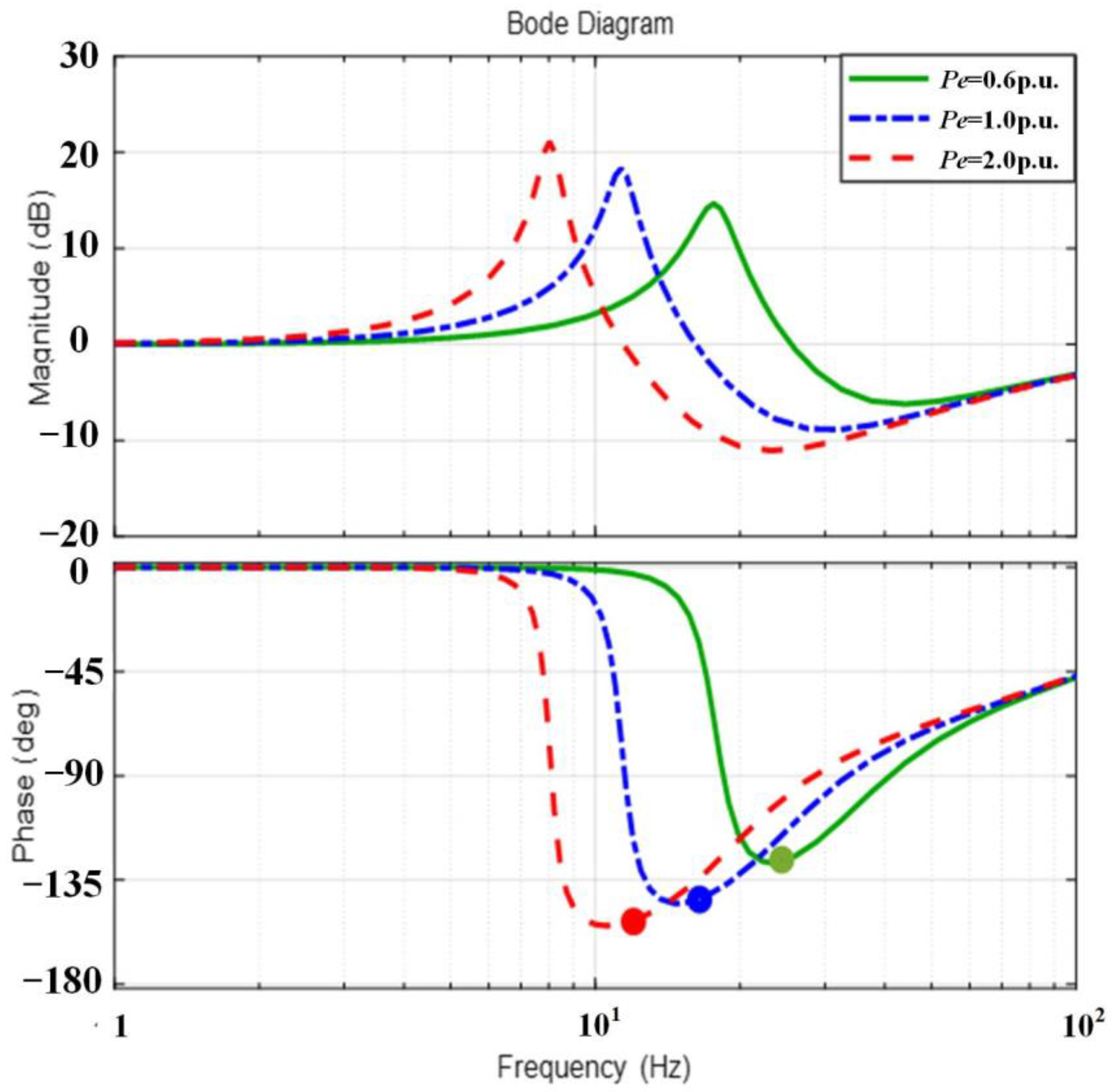
Considering that there are two torques, synchronizing and damping torques to synthesize the electromagnetic torque in Δ θ g and Δ ω g coordinates, their stability contributions need to be identified. Figure 12, Figure 13 and Figure 14 show the Bode diagram of G2(s) with varied grid strengths, operating points, and Df. In Figure 12, the phase margin is reduced with heavier load. However, the phase margin is positive in these three cases, which means their internal voltages are still stable. Figure 13 presents the phase margin of G2(s) with different Df. When Df = 0.1 and 3.5, the phase margin of G2(s) is positive, whereas the margin becomes negative with Df = −1.5 and the system becomes unstable. Figure 14 illustrates the Bode diagram of G2(s) with variant grid strengths evaluated by different SCRs. The phase margins have few changes when synchronverter is connected to both strong and weak grid, the system is still stable. In other words, the internal voltage stability of the synchronverter has more reliability with the disturbance from the weak grid than conventional VSCs.
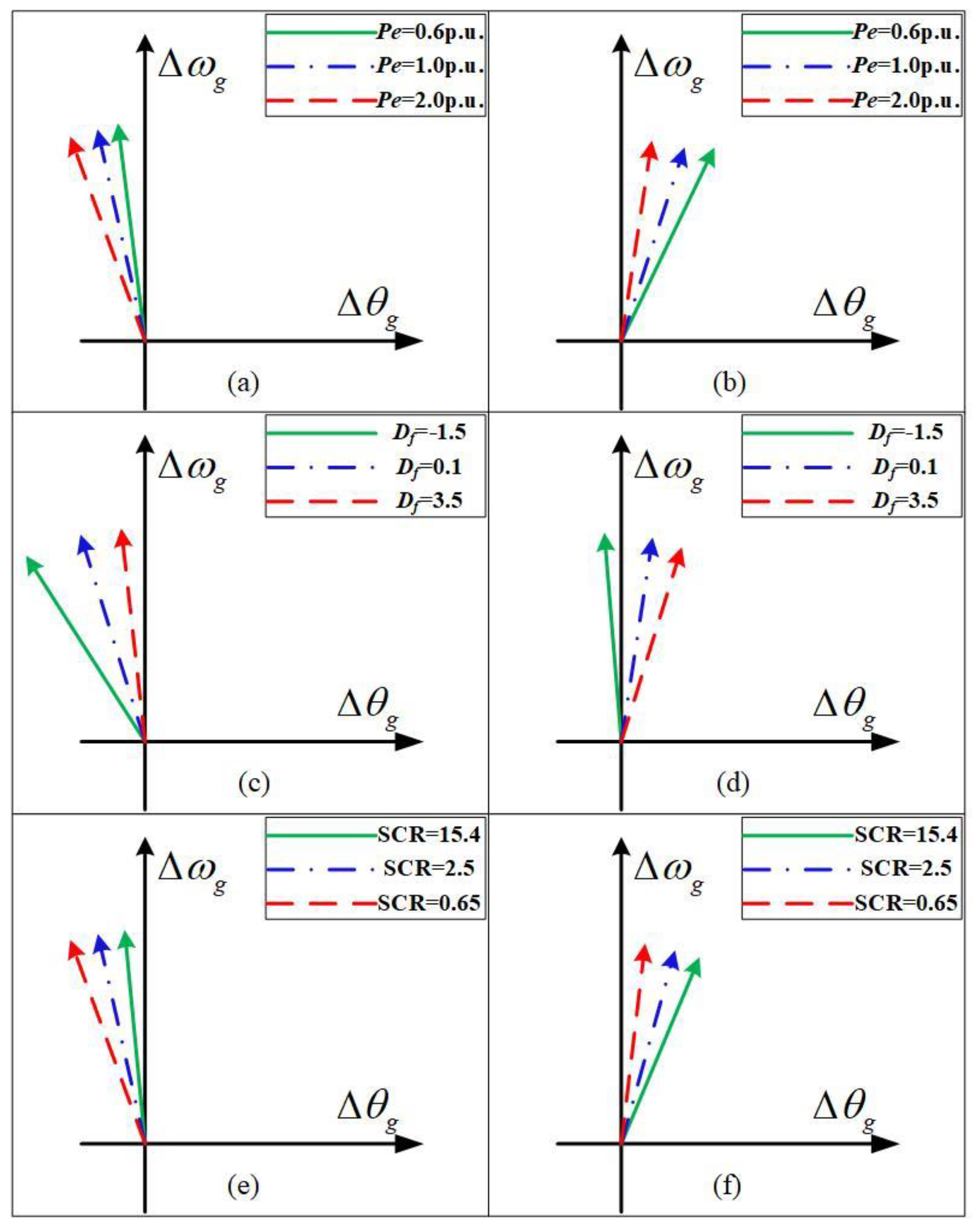
Figure 15 shows the additional synchronizing torque projected on the Δ θ g -axis with different scenarios. In Figure 15a, the additional synchronizing torques obtained by Δ T e 1 projections on the Δ θ g -axis are all negative if the operation points are changed. The difference lies in the absolute value of the negative synchronizing torque. It is obvious that it is growing larger with the increasing Pe. Due to the existence of another synchronizing torque, the negative synchronizing torque can be synthesized positively and the stable internal voltage is obtained, as shown in Figure 15b. The transient stability is better than the case with the increased operating points. The same analysis method can be implemented in the case with varying values of Df and grid strengths, the results are presented in Figure 15c–f. In Figure 15c,d, the absolute value of negative synchronizing torque projected on Δ θ g by Te1 is larger with negative Df than the cases with positive Df = 0.1 and 3.5. The overall synthetical synchronizing torque with Df = −1.5 will be negative since it is overwhelmingly negative, and the synthetical torque becomes positive when Df = 0.1 and 3.5, as shown in Figure 15d. In this sense, the internal voltage will lose the stability with Df = −1.5 whereas the opposite results are obtained with the positive Df. It is noticeable that the grid strength has little effect on synchronverter internal voltage stability, which can be reflected that the system is still stable with SCR = 0.65 as shown in Figure 15e,f. It is demonstrated that the ratio of negative synchronizing torque is slightly changed when the grid is getting weaker, which means the synchronverters have strong robustness against weak grid disturbance.

5. Simulation Results

To verify the validity of the internal voltage stability analysis method and results in Section 4, a synchronverter system is built in SIMULINK/MATLAB. The specification of a synchronverter is shown in Table 2. The internal voltage dynamics on different scenarios with variant disturbances are obtained.
Figure 16 illustrates the dynamics of synchronverter internal voltage with variant grid strengths. It can be observed that the disturbance from weak or stiff grids cannot influence the overall synchronverter stability. This phenomenon is in coordination with the analysis results described in Figure 11 and Figure 14, and phasor diagram in Figure 16a–c. The dynamics of the internal voltage with changed active power outputs are shown in Figure 17. The internal voltage has some oscillations under the different operating point Pe. It restored more quickly when the synchronverter supplies less active power to the grid. The operation points have little impact on system stability, which is coordinated with the conclusions drawn from Figure 9 and Figure 12, phasor diagram of Figure 15a,b. The results are different when the coefficient Df is altered. The internal voltage is kept stable when Df is positive and chosen as 3.5 and 0.1 and the dynamics response becomes a diverging oscillation when Df is set as −1.5, which means the internal voltage is unstable. It reaches the conclusions obtained in Figure 9 and Figure 12. The phasor diagram is displayed in Figure 18.
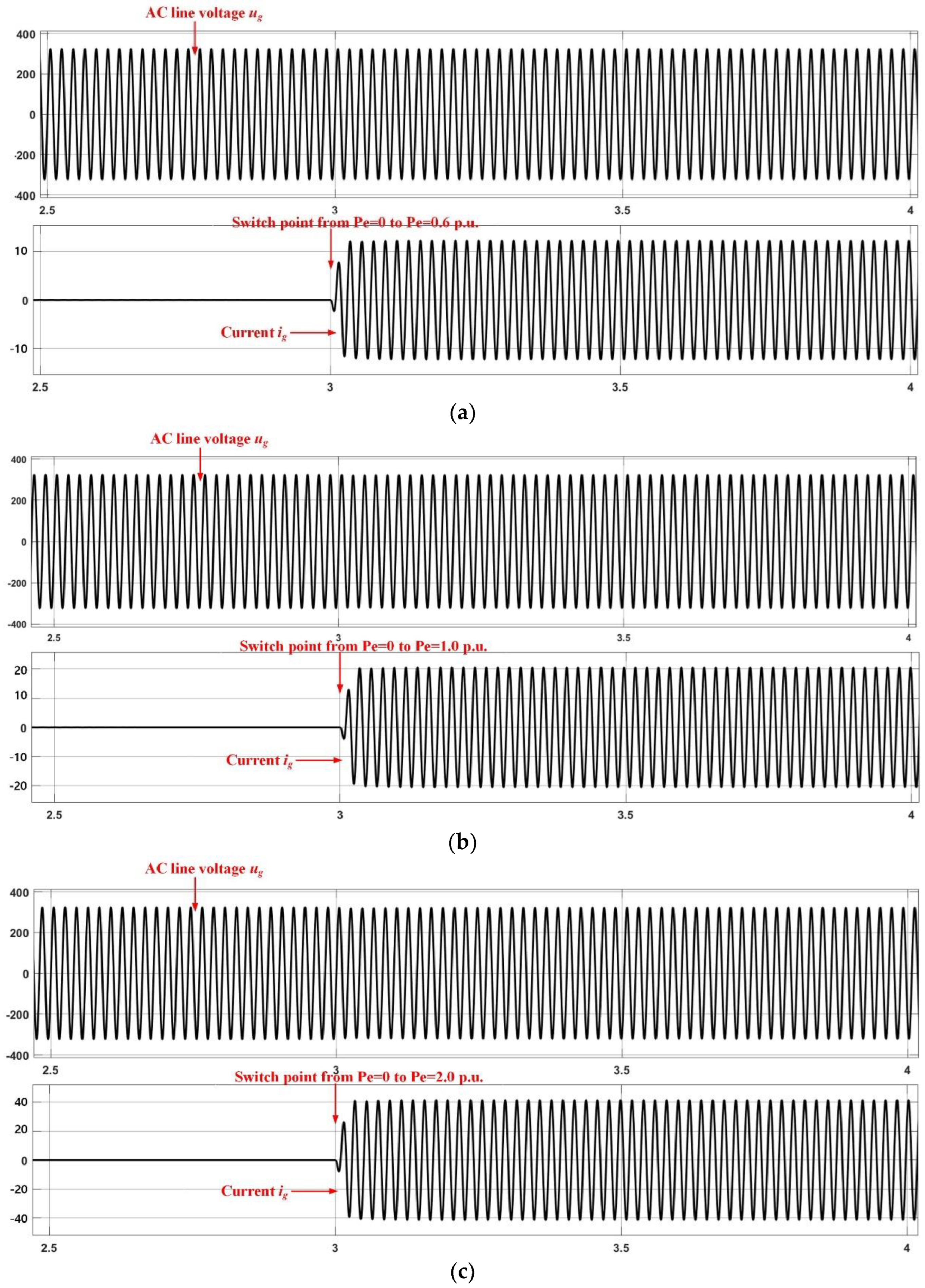
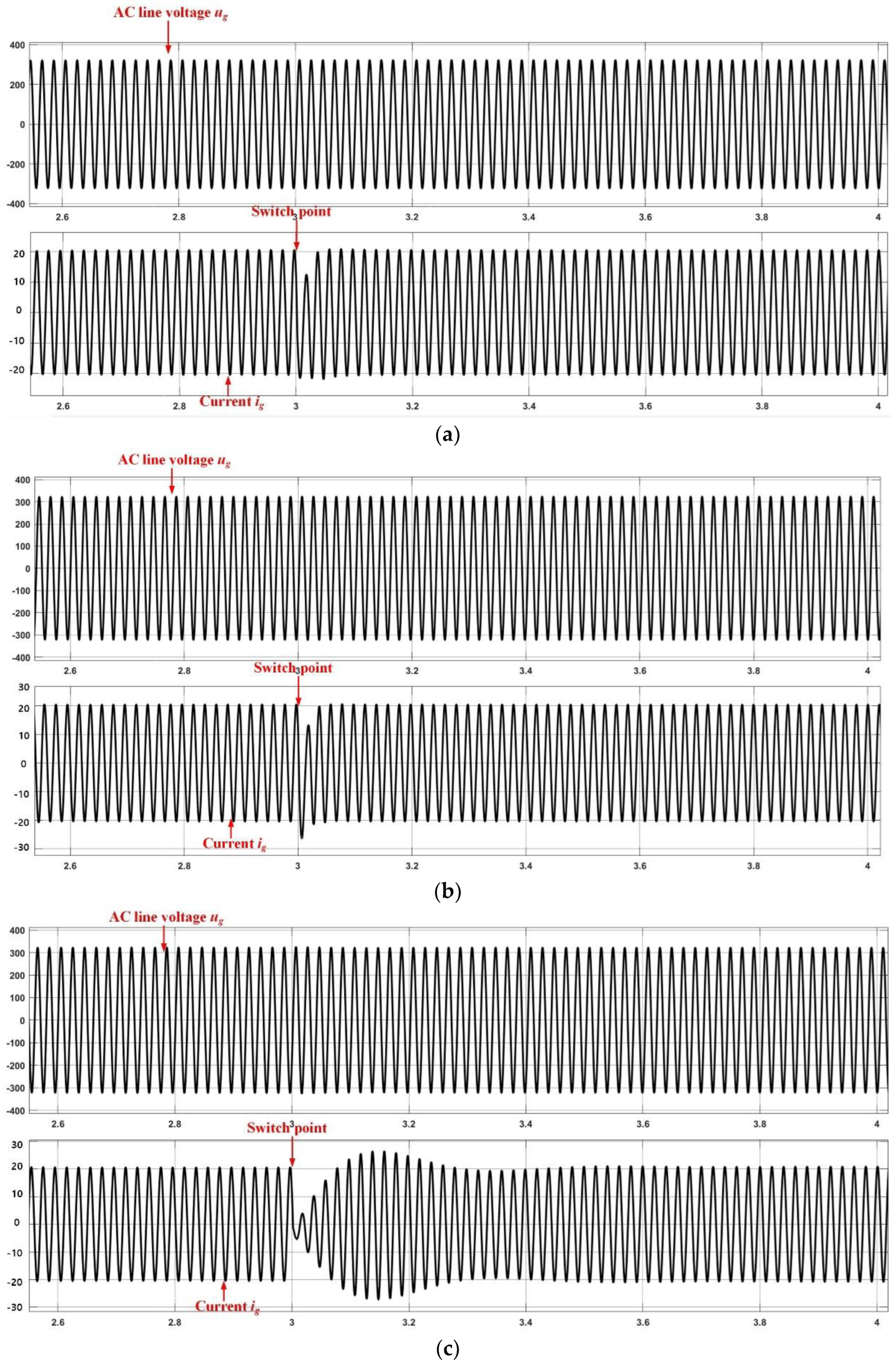
Figure 19 shows the waveforms of AC line voltage ug, synchronverter output current ig, and disturbances with switchovers among different operating points. It is demonstrated that the system is kept stable when the system is switched from 0 to operating points Pe = 0.6 p. u., 1.0 p. u., and Pe = 2.0 p. u. The oscillation during Pe transition is almost neglected as shown in the results of the synchronverter current and voltage. It is validated that synchronverters have the robustness against disturbance of operating point changes, in which the results of internal voltage are similar to the results shown in Figure 9a, Figure 12a, Figure 15a and Figure 9b, Figure 12b, Figure 15b, respectively.
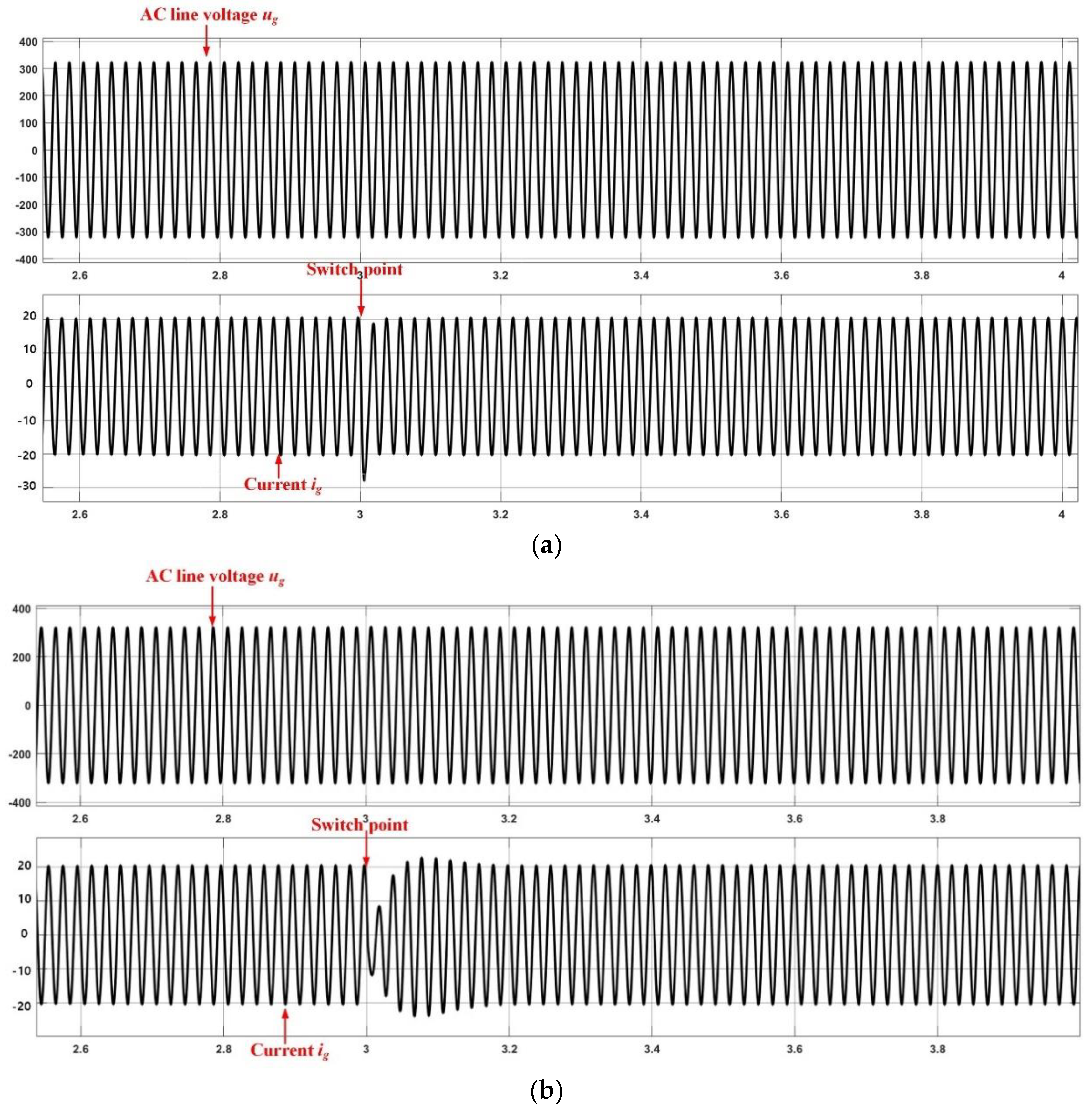
Figure 20 shows the results of AC line voltage ug, synchronverter output current ig, with disturbance having changed grid impedance in the condition of Pe = 1.0 p. u. As shown, the simulation was carried out to realize SCR switching from the initial SCR = 3 to SCR = 15.4, 1.0, and 0.65 at the switch point, t = 3 s, respectively. It is indicated that both overshoot and transient time in synchronverter current and voltage are small. It also reveals that internal voltage stability is weaker with the reduction of grid strength. Due to the introduction of extra damping and synchronizing torques imposed by synchronverters, the transient stability is still guaranteed in a wide range even when the synchronverter is suddenly connected to an extremely weak grid. It adheres to the analysis results shown in Figure 11e, Figure 14e, Figure 15e and Figure 11f, Figure 14f, Figure 15f, respectively.
Figure 21 illustrates responses of AC line voltage ug, synchronverter output current ig, and disturbance signal with different Df in the condition of switching grid impedance from SCR = 3 to 0.65 at t = 3 s. As demonstrated in Figure 20c, the transient stability of a synchronverter is influenced by the grid strength indicated by setting time and oscillation degree. We proposed an auxiliary correction control loop (shown in Figure 8) to improve the transient dynamics without changing the steady-state performance. In contrast, the proposed control loop is added in a synchronverter with coefficient Df = 3.5 in the condition similar to Figure 20c. The results shown in Figure 21a verify that the transient dynamics are much better after using the proposed correction loop. In other words, the proposed loop can dramatically improve the transient performance against some disturbances. However, inappropriate coefficient designs of Df would jeopardize the transient stability or even lead to system collapse due to the insufficient damping or synchronizing torques. For example, the damping torque falls in the second quadrant to weaken the synthetic torque when Df = −1.5. As a result, the synchronverter will lose its transient stability as shown in Figure 21c. The simulation results coordinate with the results from Figure 15c,d and Figure 18. From a contrastive transient dynamics point of view, a synchronverter has more robustness against all kinds of disturbances than other conventional VSC.

6. Conclusions

This paper presents and develops the stability analysis method based on internal voltage stability for synchronverters. As opposed to SG, synchronverters have more control flexibility to change the transient dynamics. By contrast between synchronverters and SG, the similarity is identified. Accordingly, the concepts of inertia, damping torque, and synchronous torque are used to describe synchronverter internal voltage’s characteristics in electromechanical timescale. Through the analysis, synchronizing torque is in phase with the variance of internal voltage phase, used to synchronize the phase between the synchronverter and grid. Damping torque can damp the frequency oscillation. To investigate the internal voltage stability, phasor diagrams and Bode diagrams are analyzed. In addition, an auxiliary correction control loop across APL and RPL is proposed and added in the synchronverter control loop to enhance the robustness of synchronverters under disturbances. To verify the validity of the analysis method, the simulations are conducted, and the results are basically coordinated with the theoretical analysis. By using the method of internal voltage stability, the synchronverter can be explored from the perspective of physical insight and mechanism explanation, offering the novel idea in transient stability improvement.
From the perspective of practical application, synchronverters have been applied in many scenarios and projects in the world. The first and the largest scale of transformation for the main network project, Zhangbei wind-PV-storage base with an adjustment capacity of 547.5 MW, was built in 2016 and made a great contribution to the power supply of the 2022 Winter Olympics in Beijing. Compared with traditional synchronous generators, synchronverters are more effective in improving the new energy consumption capacity and its large-scale power supply conducted by new energy. A similar story is spreading to the UK, Germany, Ireland, etc. Synchronverter technique is gradually being incorporated into synchronous grid systems that accept a high proportion of new energy sources. The economic significance of this paper lies in the improvement and detailed theoretical analysis of the inverter-derived VSG control, so as to better respond to the cooperative design of the new energy carrier.
Author Contributions

Conceptualization, Y.Z. and J.M.; methodology, F.Z.; validation, N.H.; formal analysis, Y.Z. and J.M.; investigation, Y.Z.; resources, J.M.; writing—original draft preparation, Y.Z.; writing—review and editing, J.M.; supervision, N.H.; project administration, F.Z. All authors have read and agreed to the published version of the manuscript.

Funding

This work was funded by the National Science Foundation of China under Grant 51877058, Zhejiang R&D Key Research Plan under grant 2021C01144.

Institutional Review Board Statement

Not applicable.

Informed Consent Statement

Not applicable.

Data Availability Statement

Not applicable.

Conflicts of Interest

The authors declare no conflict of interest.

References

  1. Blaabjerg, F.; Teodorescu, R.; Liserre, M.; Timbus, A.V. Overview of control and grid synchronization for distributed power generation systems. IEEE Trans. Ind. Electron. 2006, 53, 1398–1409. [Google Scholar] [CrossRef] [Green Version]
  2. Blaabjerg, F.; Yang, Y.; Yang, D.; Wang, X. Distributed power generation systems and protection. Proc. IEEE 2017, 105, 1311–1331. [Google Scholar] [CrossRef] [Green Version]
  3. Xiaoling, X.; Chao, W.; Blaabjerg, F. An improved synchronization stability method of virtual synchronous generators based on frequency feedforward on reactive power control loop. IEEE Trans. Power Electron. 2021, 36, 9136–9148. [Google Scholar]
  4. Quintero, J.; Vittal, V.; Heydt, G.T.; Zhang, H. The impact of increased penetration of converter control-based generators on power system modes of oscillation. IEEE Trans. Power Syst. 2014, 29, 2248–2256. [Google Scholar] [CrossRef]
  5. Fang, J.; Li, H.; Tang, Y.; Blaabjerg, F. On the inertia of future more-electronics power systems. IEEE J. Emerg. Sel. Top. Power Electron. 2019, 7, 2130–2146. [Google Scholar] [CrossRef]
  6. Chen, M.; Zhou, D.; Blaabjerg, F. Modelling, implementation, and assessment of virtual synchronous generator in power systems. J. Mod. Power Syst. Clean Energy. 2020, 8, 399–411. [Google Scholar] [CrossRef]
  7. Kroposki, B.; Johnson, B.; Zhang, Y.; Gevorgian, V.; Denholm, P.; Hodge, B.; Hannegan, B. Achieving a 100% renewable grid: Operating electric power systems with extremely high levels of variable renewable energy. IEEE Power Energy Mag. 2017, 15, 61–73. [Google Scholar] [CrossRef]
  8. Chen, M.; Zhou, D.; Blaabjerg, F. Enhanced transient angle stability control of grid-forming converter based on virtual synchronous generator. IEEE Trans. Ind. Electron. 2022, 69, 9133–9144. [Google Scholar] [CrossRef]
  9. Liu, J.; Miura, Y.; Ise, T. Comparison of dynamic characteristics between virtual synchronous generator and droop control in inverter-based distributed generators. IEEE Trans. Power Electron. 2016, 31, 3600–3611. [Google Scholar] [CrossRef]
  10. Hou, X.; Sun, Y.; Zhang, X.; Lu, J.; Wang, P.; Guerrero, J.M. Improvement of frequency regulation in VSG-based AC microgrid via adaptive virtual inertia. IEEE Trans. Power Electron. 2020, 35, 1589–1602. [Google Scholar] [CrossRef]
  11. Zhong, Q.-C.; Weiss, G. Synchronverters: Inverters that mimic synchronous generators. IEEE Trans. Ind. Electron. 2011, 58, 1259–1267. [Google Scholar] [CrossRef]
  12. Dong, S.; Chen, Y.C. Adjusting synchronverter dynamic response speed via damping correction loop. IEEE Trans. Energy Convers. 2017, 32, 1589–1602. [Google Scholar] [CrossRef]
  13. Zisen, Q.; Chih-Hsien, P.J.; Yang, H.; Srinivasan, D. Modeling and analysis of inner controls effects on damping and synchronizing torque components in VSG-controlled converter. IEEE Trans. Energy Convers. 2020, 36, 608–619. [Google Scholar]
  14. Du, W.; Fu, Q.; Wang, H.F. Power system small-signal angular stability affected by virtual synchronous generators. IEEE Trans. Power Syst. 2019, 34, 3209–3219. [Google Scholar] [CrossRef]
  15. Wang, Z.; Yi, H.; Zhuo, F.; Wu, J.; Zhu, C. Analysis of parameter influence on transient active power circulation among different generation units in microgrid. IEEE Trans. Ind. Electron. 2021, 68, 248–257. [Google Scholar] [CrossRef]
  16. Wu, H.; Ruan, X.; Yang, D.; Chen, X.; Zhao, W.; Lv, Z.; Zhong, Q.C. Small-signal modeling and parameters design for virtual synchronous generators. IEEE Trans. Ind. Electron. 2016, 63, 4292–4303. [Google Scholar] [CrossRef]
  17. Mo, O.; D’Arco, S.; Suul, J.A. Evaluation of virtual synchronous machines with dynamic or quasi-stationary machine models. IEEE Trans. Ind. Electron. 2017, 64, 5952–5962. [Google Scholar] [CrossRef] [Green Version]
  18. Khajehoddin, S.A.; Karimi-Ghartemani, M.; Ebrahimi, M. Grid-supporting inverters with improved dynamics. IEEE Trans. Ind. Electron. 2019, 66, 3655–3667. [Google Scholar] [CrossRef]
  19. Liu, J.; Miura, Y.; Bevrani, H.; Ise, T. A unified modeling method of virtual synchronous generator for multi-operation-mode analyses. IEEE J. Emerg. Sel. Top. Power Electron. 2021, 9, 2394–2409. [Google Scholar] [CrossRef]
  20. Pan, D.; Wang, X.; Liu, F.; Shi, R. Transient stability of voltage-source converters with grid-forming control: A design-oriented study. IEEE J. Emerg. Sel. Top. Power Electron. 2020, 8, 1019–1033. [Google Scholar] [CrossRef]
  21. Shuai, Z.; Shen, C.; Liu, X.; Li, Z.; Shen, Z. Transient angle stability of virtual synchronous generators using Lyapunov’s direct method. IEEE Trans. Smart Grid. 2019, 10, 4648–4661. [Google Scholar] [CrossRef]
  22. Xin, H.; Huang, L.; Zhang, L.; Wang, Z.; Hu, J. Synchronous instability mechanism of P-f droop-controlled voltage source converter caused by current saturation. IEEE Trans. Power Syst. 2016, 31, 5206–5207. [Google Scholar] [CrossRef]
  23. Li, M.; Shu, S.; Wang, Y.; Yu, P.; Liu, Y.; Zhang, Z.; Hu, W.; Blaabjerg, F. Analysis and improvement of large-disturbance stability for grid-connected VSG based on output impedance optimization. IEEE Trans. Power Electron. 2022, 8, 9807–9826. [Google Scholar] [CrossRef]
  24. Xiong, L.; Zhuo, F.; Wang, F.; Liu, X.; Chen, Y.; Zhu, M.; Yi, H. Static synchronous generator model: A new perspective to investigate dynamic characteristics and stability issues of grid-tied PWM Inverter. IEEE Trans. Power Electron. 2016, 31, 6264–6280. [Google Scholar] [CrossRef]
  25. Zhong, Q.-C.; Konstantopoulos, G.C.; Ren, B.; Krstic, M. Improved synchronverters with bounded frequency and voltage for smart grid integration. IEEE Trans. Smart Grid. 2018, 2, 786–796. [Google Scholar] [CrossRef] [Green Version]
  26. Kuehn, W. Control and stability of power inverters feeding renewable power to weak AC grids with no or low mechanical inertia. In Proceedings of the 2009 IEEE/PES Power Systems Conference and Exposition, Seattle, WA, USA, 15–18 March 2009; pp. 1–8. [Google Scholar]
  27. Huang, Y.; Zhai, X.; Hu, J.; Dong, L.; Chang, L. Modeling and stability analysis of VSC internal voltage in DC-link voltage control timescale. IEEE J. Emerg. Sel. Top. Power Electron. 2018, 6, 16–30. [Google Scholar] [CrossRef]
  28. Wang, D.; Hou, Y.; Hu, J. Comparative analysis of stability limitations in weak grid-connected synchronous generator, VSC, and DFIG systems considering the power flow control dynamics. IET Renew. Power Gener. 2019, 1, 94–102. [Google Scholar] [CrossRef]
  29. Dong, S.; Chen, Y.C. A method to directly compute synchronverter parameters for desired dynamic response. IEEE Trans. Energy Convers. 2018, 2, 814–827. [Google Scholar] [CrossRef]
Figure 1. Schematic of the synchronverter main circuit, control system, and grid interface. (a) APL; (b) RPL; (c) power system of the synchronverter.
Electronics 12 00700 g001
Figure 2. Small-signal model of the single synchronous generator infinite bus system [28].
Electronics 12 00700 g002
Figure 3. Four-vector diagram for synchronverter control dynamics: (a) steady state; (b) transient state during a disturbance.
Electronics 12 00700 g003
Figure 4. Diagram for demonstrating variations of damping torque ΔTd and synchronizing torque ΔTs.
Electronics 12 00700 g004
Figure 5. Diagram for demonstrating concepts of damping torque and synchronizing torque: (a) phasor diagram of damping and synchronizing torque; (b) impacts of damping and synchronizing torques on internal voltage stability.
Electronics 12 00700 g005
Figure 6. The dynamics of synchronverter internal voltage under two special circumstances: (a) negative damping torque; (b) negative synchronizing torque.
Electronics 12 00700 g006
Figure 7. Phasor diagram for demonstrating the leading effect of damping torque on internal voltage stability: (a) normal condition; (b) abnormal condition with changed damping torque under disturbances.
Electronics 12 00700 g007
Figure 8. Proposed synchronverter controller with auxiliary correction loop.
Electronics 12 00700 g008
Figure 9. Bode diagram of G1(s) for different operating points.
Electronics 12 00700 g009
Figure 10. Bode diagram of G1(s) for different values of Df.
Electronics 12 00700 g010
Figure 11. Bode diagram of G1(s) for different grid strengths.
Electronics 12 00700 g011
Figure 12. Bode diagram of G2(s) for different operating points.
Electronics 12 00700 g012
Figure 13. Bode diagram of G2(s) for different values of Df.
Electronics 12 00700 g013
Figure 14. Bode diagram of G2(s) for different grid strengths.
Electronics 12 00700 g014
Figure 15. Phasor diagrams of Δ T e 1 (a,c,e) and Δ T e (b,d,f) with varying operating points, values of Df in auxiliary correction loop and grid strengths.
Electronics 12 00700 g015
Figure 16. Internal voltage dynamics with different grid strengths: (a) SCR = 15.4; (b) SCR = 2.5; (c) SCR = 0.65.
Electronics 12 00700 g016
Figure 17. Internal voltage dynamics with different active output power: (a) Pe = 0.6 p.u; (b) Pe = 1.0 p.u; (c) Pe = 2.0 p.u.
Electronics 12 00700 g017
Figure 18. Internal voltage dynamics with different values of Df: (a) Df = 3.5; (b) Df = 0.1; (c) Df = −1.5.
Electronics 12 00700 g018
Figure 19. Dynamics of AC line voltage, synchronverter current, and disturbance with the switching operating point: (a) from Pe = 0 to Pe = 0.6 p.u.; (b) from Pe = 0 to Pe = 1.0 p.u.; (c) from Pe = 0 to Pe = 2.0 p.u.
Electronics 12 00700 g019
Figure 20. Dynamics of AC line voltage, synchronverter current, and disturbance with different grid strengths: (a) responses with SCR = 15.4; (b) responses with SCR = 2.5; (c) responses with SCR = 0.65.
Electronics 12 00700 g020
Figure 21. Dynamics of AC line voltage, synchronverter current, and disturbance with varied Df in the proposed auxiliary correction loop: (a) responses with Df = 3.5; (b) responses with Df = 0.1; (c) responses with Df = −1.5.
Electronics 12 00700 g021aElectronics 12 00700 g021b
Table 1. Characteristic comparison between VSG and SG.
Power TypeInertia TypeEnergy SourceParameter ControlHarmonic Characteristics
SGsynchronous inertia prime motorconstantlow-order harmonic
Voltage-source VSCvirtual synchronous inertiaPhotovoltaics, wind turbine, storage FlexibleHigh/medium/low-order harmonics
Current-source VSGFast frequency response
Table 2. Synchronverter specifications.
SymbolQuantityValues
LsOutput inductance2.2 mH
LeGrid filter inductance3.75 mH
S1Switch 11
S2Switch 20
DpDamping coefficient1407 N·m·s/rad
DqVoltage droop coefficient3711 Var/V
JgVirtual inertia coefficient2.814 kg·m2
KReactive power regulator gain27,980 Var·rad/V
VDCDC-link voltage720 V
UGrid voltage398.37 V
PsetRated DC power capacity3.6 MVA
VgRated voltage398.37 V
Disclaimer/Publisher’s Note: The statements, opinions and data contained in all publications are solely those of the individual author(s) and contributor(s) and not of MDPI and/or the editor(s). MDPI and/or the editor(s) disclaim responsibility for any injury to people or property resulting from any ideas, methods, instructions or products referred to in the content.