


Antipodal Linearly Tapered Slot Antenna with Quasi-Hemispherical Pattern Using Subwavelength Elements

Abstract
:1. Introduction
2. Antenna Configuration and Performance Analysis
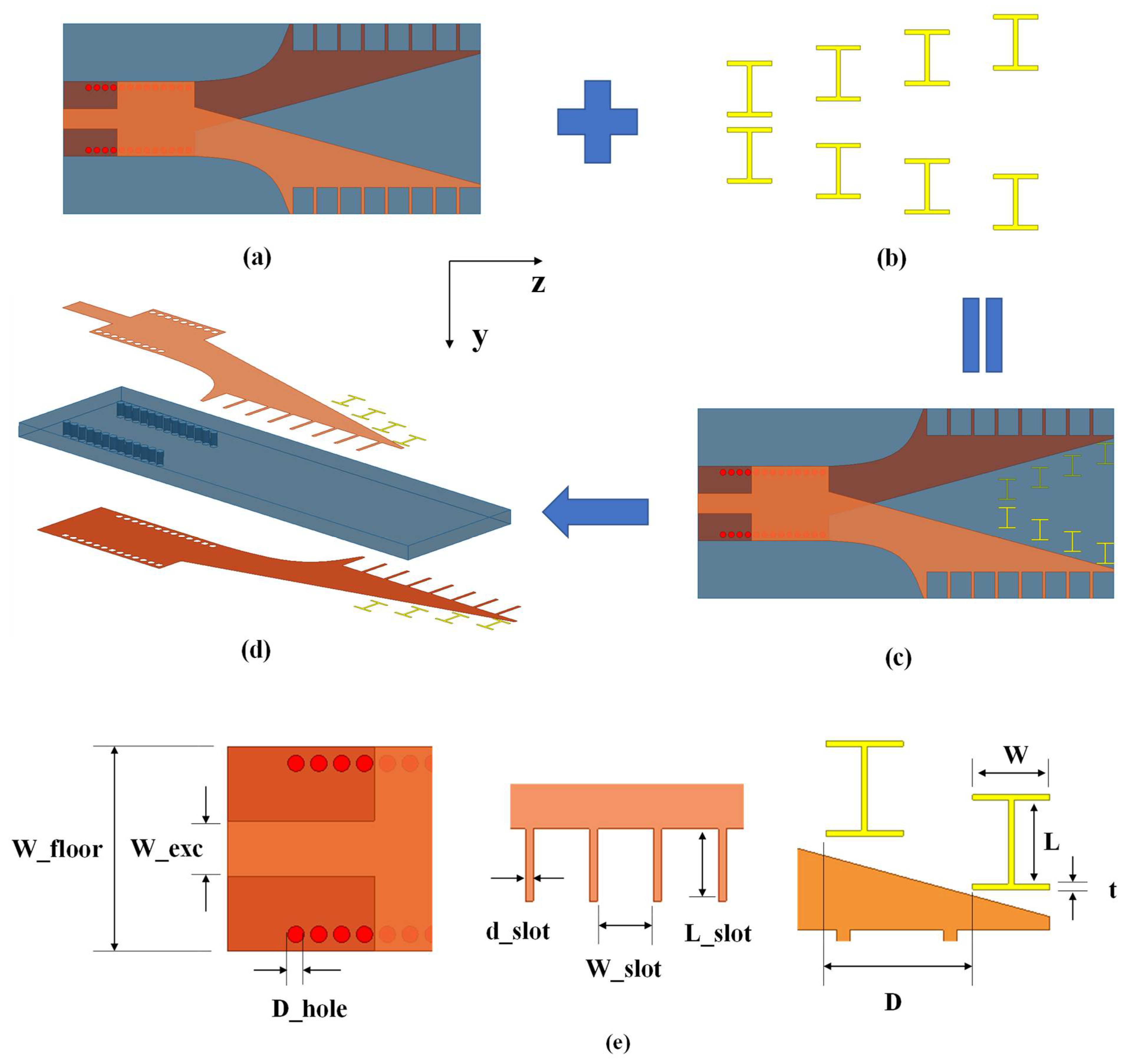
2.1. Antenna Configuration
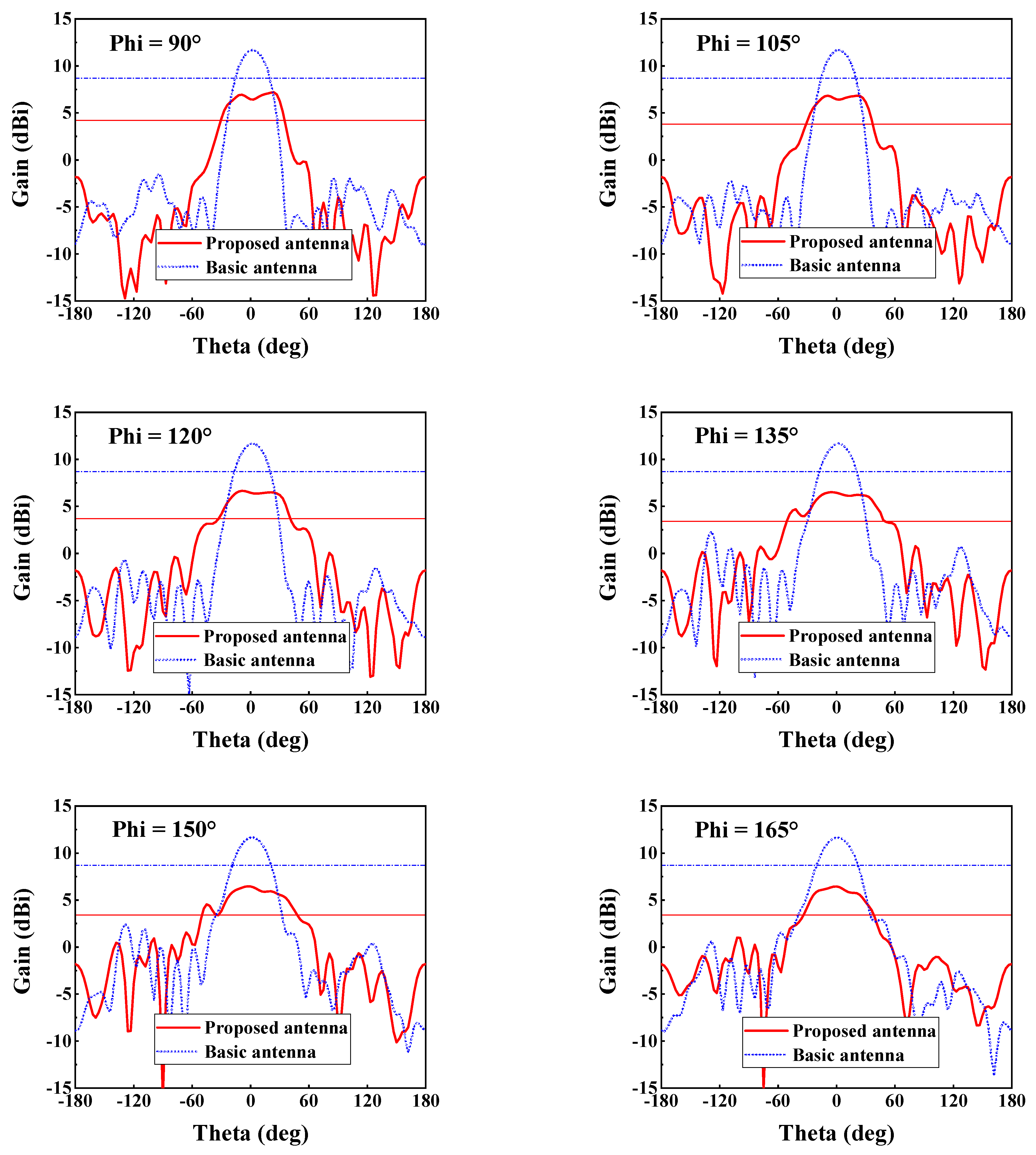
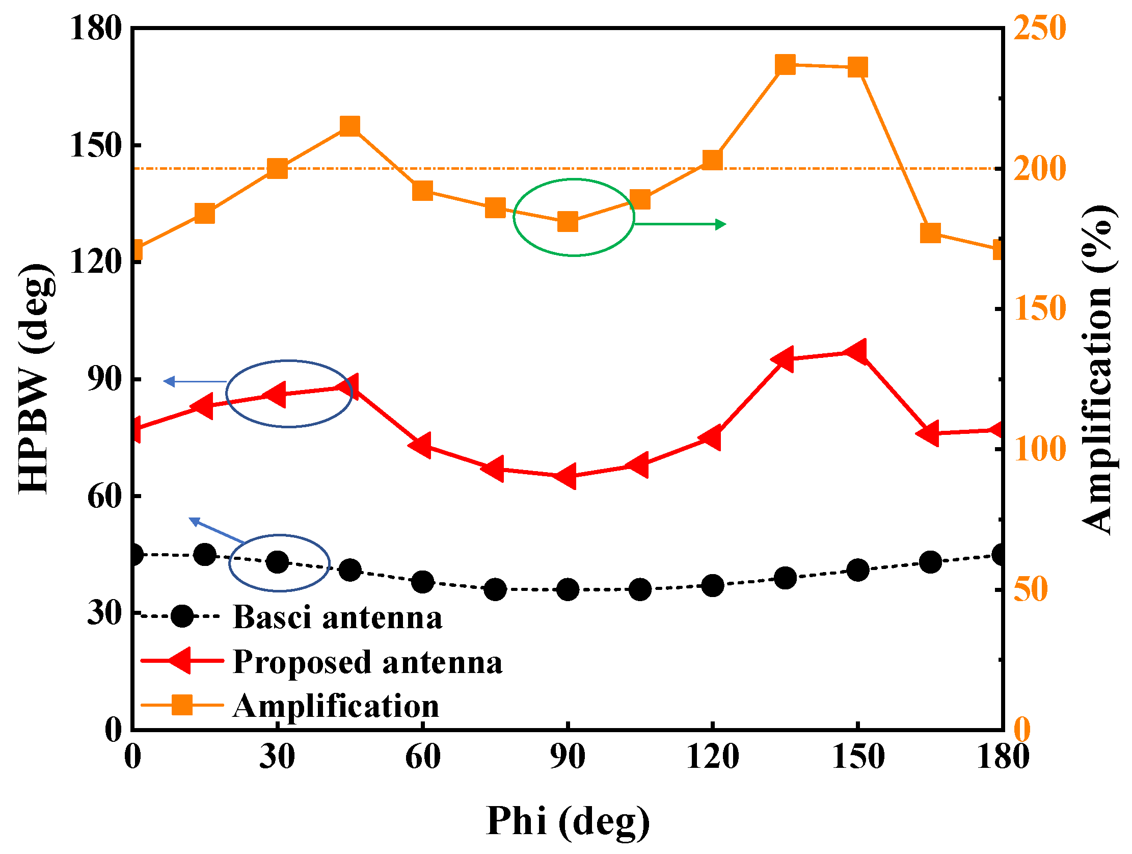
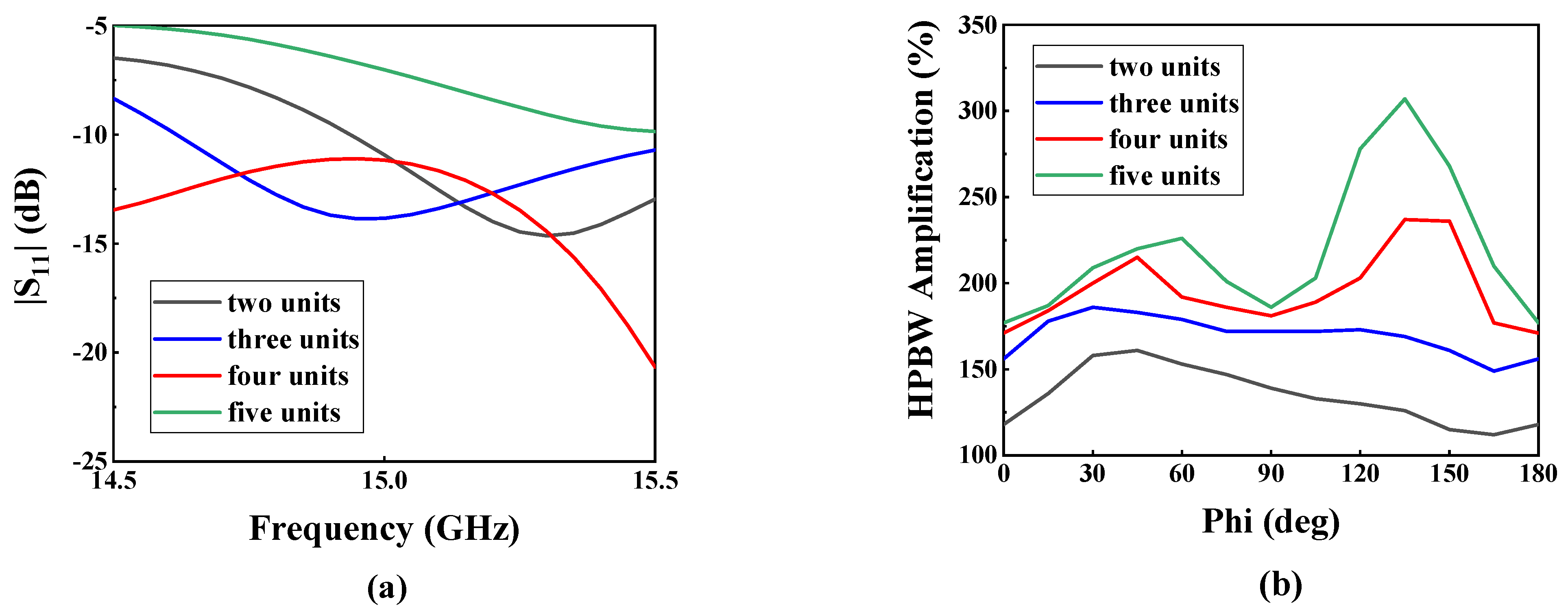
2.2. Simulated Results and Analysis
2.3. Performance Comparison
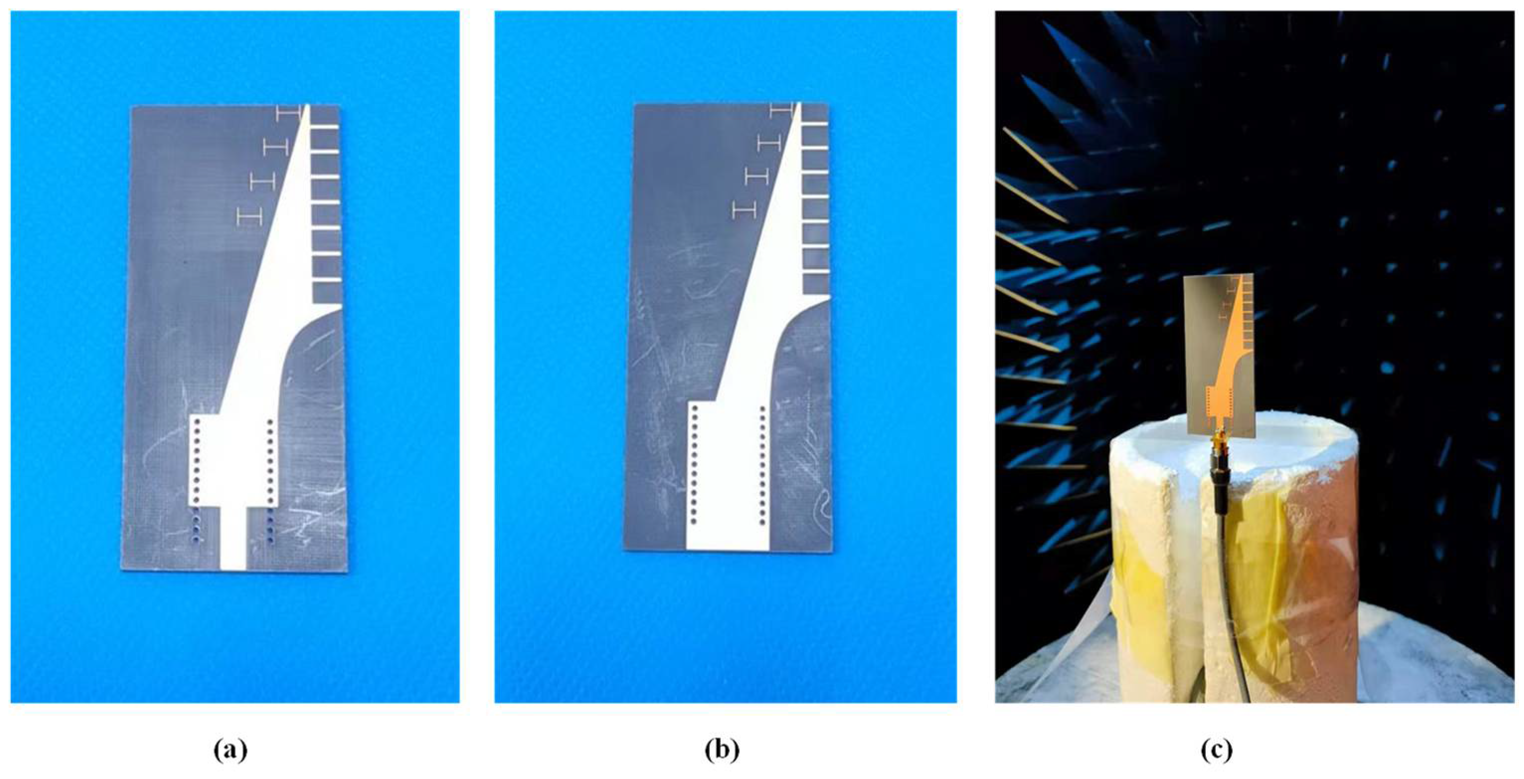
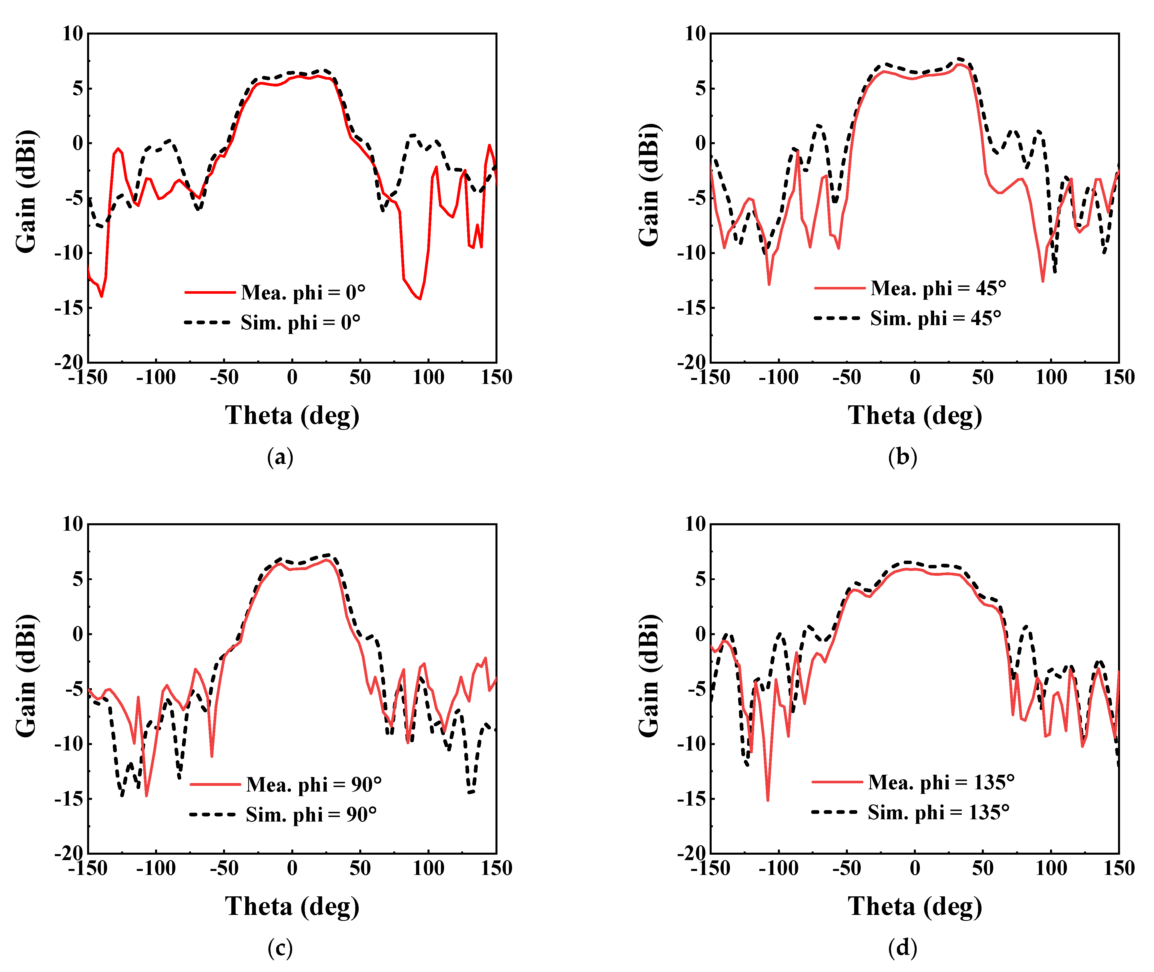
3. Fabrication and Measurement
4. Conclusions
Author Contributions
Funding
Data Availability Statement
Conflicts of Interest
References
- Wang, T.; Huang, K.; Zhang, B.; Liu, W.; Zhang, Z.; Hou, J.; Rasool, N. A Novel Lens Antenna with Wide Beamwidth Using Three Dimensional Printing. Microw. Opt. Technol. Lett. 2021, 63, 2192–2198. [Google Scholar] [CrossRef]
- Yang, N.; Weng, Z.; Wang, L.; Liao, T. A Hybrid Dual-Mode Dielectric Resonator Antenna with wide Beamwidth. Int. J. RF Microw. Comput. Aided Eng. 2020, 30, e22337. [Google Scholar] [CrossRef]
- Wang, J.Y.; Lu, W.J.; Zhang, W.L.; Zhu, L. Balanced Low-Profile Wide Beamwidth Circularly Polarized Stacked Loop Antenna. Int. J. RF Microw. Comput. Aided Eng. 2021, 31, e22848. [Google Scholar] [CrossRef]
- Zhang, W.-H.; Xue, Q.; Liao, S.; Che, W.; Yang, W. Low-Profile Compact Microstrip Magnetic Dipole Antenna with Large Beamwidth and Broad Bandwidth for Vehicular Applications. IEEE Trans. Veh. Technol. 2021, 70, 5445–5456. [Google Scholar] [CrossRef]
- Pradhan, S.; Gupta, B. Radome Enclosed Circularly Polarized Antenna System with Enhanced Beamwidth. Radioengineering 2022, 31, 54–61. [Google Scholar] [CrossRef]
- Mashhadi, S.H.H.; Jiao, Y.-C.; Chen, J. Wide 3-dB Beamwidth Step-Walled Rectangular Dielectric Resonator Antenna. J. Electromagn. Waves Appl. 2020, 34, 349–361. [Google Scholar] [CrossRef]
- Zhao, Z.-B.; Lu, W.-J.; Zhu, L.; Yu, J. Wideband Wide Beamwidth Full-Wavelength Sectorial Dipole Antenna under Dual-Mode Resonance. IEEE Trans. Antennas Propag. 2021, 69, 14–24. [Google Scholar] [CrossRef]
- Zhang, Y.-Q.; Qin, S.-T.; Li, X.; Guo, L.-X. Novel Wide-Beam Cross-Dipole CP Antenna for GNSS Applications. Int. J. RF Microw. Comput. Aided Eng. 2018, 28, e21272. [Google Scholar] [CrossRef]
- Yang, X.; Liu, X. Design of a Wide-Beam Microstrip Array Antenna for Automotive Radar Application. IEEE Access 2021, 9, 142340–142347. [Google Scholar] [CrossRef]
- Li, Z.; Zhang, G.; Golbon-Haghighi, M.-H.; Saeidi-Manesh, H.; Herndon, M.; Pan, H. Initial Observations with Electronic and Mechanical Scans Using a Cylindrical Polarimetric Phased Array Radar. IEEE Geosci. Remote Sens. Lett. 2021, 18, 271–275. [Google Scholar] [CrossRef]
- Wang, Z.; Liang, T.; Dong, Y. Metamaterial-Based, Compact, Wide Beam-Width Circularly Polarized Antenna for 5G Indoor Application. Microw. Opt. Technol. Lett. 2021, 63, 2171–2178. [Google Scholar] [CrossRef]
- Park, J.-S.; Ko, J.-B.; Kwon, H.-K.; Kang, B.-S.; Park, B.; Kim, D. A Tilted Combined Beam Antenna for 5G Communications Using a 28-GHz Band. IEEE Antennas Wirel. Propag. Lett. 2016, 15, 1685–1688. [Google Scholar] [CrossRef]
- Mittra, R.; Nasri, A.; Arya, R.K. Wide-Angle Scanning Antennas for Millimeter-Wave 5G Applications. Engineering 2022, 11, 60–71. [Google Scholar] [CrossRef]
- Wang, L.; Geng, J.; Wang, K.; Zhou, H.; Ren, C.; Wu, H.; Zhao, X.; He, C.; Liang, X.; Zhu, W.; et al. Wideband Dual-Polarized Binary Coding Antenna with Wide Beamwidth and Its Array for Millimeter-Wave Applications. IEEE Antennas Wirel. Propag. Lett. 2020, 19, 636–640. [Google Scholar] [CrossRef]
- Chen, X.; Qin, P.-Y.; Guo, Y.J.; Fu, G. Low-Profile and Wide-Beamwidth Dual-Polarized Distributed Microstrip Antenna. IEEE Access 2017, 5, 2272–2280. [Google Scholar] [CrossRef]
- Mashhadi, S.H.H.; Jiao, Y.-C.; Chen, J. Broadbeam Cylindrical Dielectric Resonator Antenna. IEEE Access 2019, 7, 112653–112661. [Google Scholar] [CrossRef]
- Li, R.Y.; Jiao, Y.C.; Zhang, Y.X.; Zhang, L.; Wang, H.Y. A DRA with Engraved Groove and Comb-like Metal Wall for Beamwidth Enhancement in Both E- and H-Planes. IEEE Antennas Wirel. Propag. Lett. 2022, 20, 543–547. [Google Scholar] [CrossRef]
- Li, Y.; Luk, K.-M. A Linearly Polarized Magnetoelectric Dipole with Wide H-Plane Beamwidth. IEEE Trans. Antennas Propag. 2014, 62, 1830–1836. [Google Scholar] [CrossRef]
- Chang, L.; Chen, L.-L.; Zhang, J.-Q.; Chen, Z.-Z. A Compact Wideband Dipole Antenna with Wide Beamwidth. IEEE Antennas Wirel. Propag. Lett. 2021, 20, 1701–1705. [Google Scholar] [CrossRef]
- Zhang, W.-H.; Xue, Q.; Liao, S.; Yang, W.; Che, W.; Chen, H. A Linearly Polarized Low-Profile Complementary Antenna with Enhanced Bandwidth and Wide Broadside Beamwidth. IEEE Antennas Wirel. Propag. Lett. 2021, 20, 1332–1336. [Google Scholar] [CrossRef]
- Su, G.-R.; Li, E.S.; Jin, H.; Hsu, P.-H.; Sun, J.-S.; Chin, K.-S. 79-GHz SIW slot-coupled patch antenna array with low cross polarization and wide beamwidth. J. Electromagn. Waves Appl. 2022, 37, 38–52. [Google Scholar] [CrossRef]
- Wang, Z.; Zhao, S.; Dong, Y. Metamaterial-Based Wide-Beam Dielectric Resonator Antenna for Broadband Wide-Angle Beam-Scanning Phased Array Applications. IEEE Trans. Antennas Propag. 2022, 70, 9061–9072. [Google Scholar] [CrossRef]
- Gibson, P.J. The Vivaldi Aerial. In Proceedings of the 1979 9th European Microwave Conference, Brighton, UK, 17–20 September 1979; pp. 101–105. [Google Scholar] [CrossRef]
- Chen, L.; Lei, Z.; Yang, R.; Fan, J.; Shi, X. A Broadband Artificial Material for Gain Enhancement of Antipodal Tapered Slot Antenna. IEEE Trans. Antennas Propag. 2015, 63, 395–400. [Google Scholar] [CrossRef]
- Zhou, B.; Cui, T.J. Directivity Enhancement to Vivaldi Antennas Using Compactly Anisotropic Zero-Index Metamaterials. IEEE Antennas Wirel. Propag. Lett. 2011, 10, 326–329. [Google Scholar] [CrossRef]
- Sun, M.; Qing, X.; Chen, Z.N. 60-GHz End-Fire Fan-Like Antennas with Wide Beamwidth. IEEE Trans. Antennas Propag. 2013, 61, 1616–1622. [Google Scholar] [CrossRef]
- Zhao, C.; Li, X.; Sun, C.; Huang, H. Single-Feed Microstrip Antenna for Wide Angle Circular Polarizations with Six Metal Columns. IET Microw. Antennas Propag. 2019, 13, 2569–2574. [Google Scholar] [CrossRef]
- Boyuan, M.; Huang, S.; Pan, J.; Liu, Y.-T.; Yang, D.; Guo, Y.-X. Higher-Order Characteristic Modes-Based Broad-Beam Dielectric Resonator Antenna. IEEE Antennas Wirel. Propag. Lett. 2022, 21, 818–822. [Google Scholar] [CrossRef]
- He, Y.; Li, Y. Dual-Polarized Microstrip Antennas with Capacitive via Fence for Wide Beamwidth and High Isolation. IEEE Trans. Antennas Propag. 2020, 68, 5095–5103. [Google Scholar] [CrossRef]


| Parameter | W_floor | W_exc | D_hole | d_slot | W_slot |
| Value | 12.5 | 3.4 | 1 | 0.5 | 3.5 |
| Parameter | L_slot | D | W | L | t |
| Value | 4.5 | 5.5 | 2.9 | 3.43 | 0.06 |
| Proposed Antenna | Basic Antenna | ||
| Amplitude | 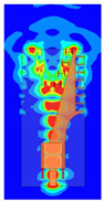 | 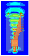 | 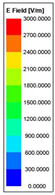 |
| Phase (Phi = 0) | 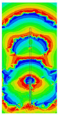 | 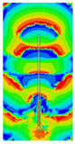 | 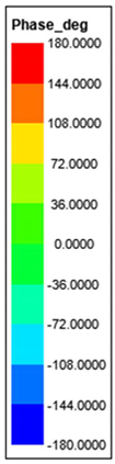 |
| Phase (Phi = 45) | 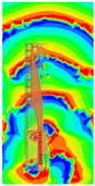 | 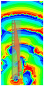 | |
| Phase (Phi = 90) | 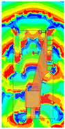 |  | |
| Phase (Phi = 135) |  |  |
| Ref. | Type | Radiation Direction | Aim at All Cut-Planes | # HPBW | * Increased Size | * Increased Complexity |
|---|---|---|---|---|---|---|
| [2] | Dielectric resonator antenna | Broadside | No | 189% | Yes | Yes |
| [14] | Patches antenna | Broadside | No | ~200% | No | Yes |
| [17] | Dielectric resonator antenna | Broadside | No | ~350% | Yes | Yes |
| [19] | Dipole antenna | Broadside | No | ~230% | Yes | Yes |
| [26] | Tapered slot antenna | End-fire | No | <200% | No | Yes |
| [27] | Microstrip antenna | Broadside | No | ~230% | Yes | Yes |
| [28] | Dielectric resonator antenna | Broadside | No | ~330% | Yes | Yes |
| [29] | Microstrip antenna | Broadside | No | 241% | No | Yes |
| This work | ALTSA | End-fire | Yes | 237% | No | No |
Disclaimer/Publisher’s Note: The statements, opinions and data contained in all publications are solely those of the individual author(s) and contributor(s) and not of MDPI and/or the editor(s). MDPI and/or the editor(s) disclaim responsibility for any injury to people or property resulting from any ideas, methods, instructions or products referred to in the content. |
© 2023 by the authors. Licensee MDPI, Basel, Switzerland. This article is an open access article distributed under the terms and conditions of the Creative Commons Attribution (CC BY) license (https://creativecommons.org/licenses/by/4.0/).
Share and Cite
Wang, R.; Liao, D.; Yang, F. Antipodal Linearly Tapered Slot Antenna with Quasi-Hemispherical Pattern Using Subwavelength Elements. Electronics 2023, 12, 628. https://doi.org/10.3390/electronics12030628
Wang R, Liao D, Yang F. Antipodal Linearly Tapered Slot Antenna with Quasi-Hemispherical Pattern Using Subwavelength Elements. Electronics. 2023; 12(3):628. https://doi.org/10.3390/electronics12030628
Chicago/Turabian StyleWang, Rui, Dashuang Liao, and Feng Yang. 2023. "Antipodal Linearly Tapered Slot Antenna with Quasi-Hemispherical Pattern Using Subwavelength Elements" Electronics 12, no. 3: 628. https://doi.org/10.3390/electronics12030628
APA StyleWang, R., Liao, D., & Yang, F. (2023). Antipodal Linearly Tapered Slot Antenna with Quasi-Hemispherical Pattern Using Subwavelength Elements. Electronics, 12(3), 628. https://doi.org/10.3390/electronics12030628