Abstract
A macro–micro dual-drive positioning system was developed for Scanning Beam Interference Lithography (SBIL) which uses a dual-frequency laser interferometer as the position reference and exhibits the characteristics of long travel, heavy load, and high accuracy. The macro-motion system adopts a friction-driven structure and a feedforward PID control algorithm, and the stroke can reach 1800 mm. The micro-motion system adopts a flexible hinge–plus-PZT driving method and a PID control algorithm based on neural networks, which achieves sufficient positioning accuracy of this system at the nanometer level. An optical-path-sealing system was used to reduce the measurement noise of the dual-frequency laser interferometer. The static stability of the positioning system, the stepping capacity of the macro-motion system, the stepping capacity of the micro-motion system, and the positioning accuracy of the system were tested and analyzed. Additionally, the sources and effects of errors during the motion process were assessed in detail. Finally, the experimental results show that the workbench can locate at the nanoscale within the full range of travel, which can satisfy the SBIL exposure requirement.
1. Introduction
Large-sized diffraction grating is an optical element widely used in scenarios such as light splitting, wavelength selection, spectral analysis, and laser modulation. The System for Scanning Beam Interference (SBIL) was an emerging technology over recent years for manufacturing large-sized diffraction gratings [1,2]. Its principle is to use two coherent Gaussian beams to form interference fringes on the substrate and a two-dimensional stage to carry the substrate for the step-scanning motion and then obtain a large-sized grating. The grating substrate for large-scale scanning exposure can typically reach hundreds of kilograms. Therefore, the travel, accuracy, stability, and load-bearing capacity of the stage directly affect the quality of the grating manufacturing in an SBIL system [3]. The main research contribution of this paper is the design and analysis of a positioning system for a two-dimensional stage in a scanning interference field.
Positioning systems are usually divided into two categories based on accuracy and stroke: long-stroke high-precision and small-stroke high-precision. Long-stroke high-precision feed systems often use linear motors, lead screws, voice coil motors, and friction drives. These drives can achieve sub-micron positioning accuracy over a travel range of tens to hundreds of millimeters, but they cannot meet nanometer-scale requirements [4,5,6]. A linear motor requires a simple structure, but poor parameter tuning can lead to steady-state vibration. Lead screws have a backlash, and ultra-high-precision lead screws are expensive. A voice coil motor is only suitable for motion in the millimeter range. A friction drive has a simple structure but requires high assembly and debugging requirements.
Small-stroke higher-precision drive systems commonly use PZT, and PZT is currently the most commonly used drive method in ultra-high-precision positioning systems [7,8]. However, because of the limitations of PZT, it is often used in conjunction with displacement amplification mechanisms, such as flexible hinges, which can achieve nanometer-scale step resolution and travel distances ranging from micrometers to hundreds of micrometers [9,10,11]. In 2022, Zhang Quan and others proposed an XY precision positioning system with PZT based on mathematical model decoupling, which could achieve nanometer-level positioning accuracy within a 170-micron stroke range [12].
To solve the contradiction between accuracy and stroke, Sharon first proposed the concept of macro–micro drive in 1984 to solve the problem of the end-effector positioning of robots, which was later widely applied in high-precision positioning systems [13,14]. The macro–micro drive method enables a positioning system to achieve ultra-high-precision positioning within a stroke range of hundreds of millimeters [15,16].
In 2022, Yu Chaofeng and others in China used voice coil motors as macro-actuators and PZTs as micro-actuators to achieve a positioning accuracy of 140 nm within a stroke range of 47 mm [17]. That same year, Su Liyun and others designed a long-stroke rigid-flex motion system based on linear motors, using Aerotech’s PRO190LM as a motion platform, achieving a bidirectional repeatability of ±0.25 μm within a stroke range of 500 mm [18]. Furthermore, Wang Fucheng and others proposed a multi-switch control method for long-stroke precision platforms, achieving fast nanometer-scale positioning accuracy within a stroke range of 100 mm in 2022 [19]. Manzhi Yang and others achieved a positioning accuracy of 0.1 arcsecond, where the macro driving method adopts the torque motor and the micro-driving method adopts piezoelectric ceramics [20].
Analyzing the various positioning systems mentioned above shows that long-range and ultra-high-precision positioning is difficult to achieve with the same driving method. However, by combining two-stage actuators with appropriate control strategies, the advantages and disadvantages of the two actuators can compensate for each other.
This paper proposes a macro–micro dual-drive high-precision long-stroke positioning system for an SBIL system. The macro–micro drives are friction drives and PZT. In addition, a dual-frequency laser interferometer is used as a position reference [21,22,23]. The experimental results show that comprehensive large-stroke and high-precision performance can be achieved.
2. Positioning System
The SBIL system includes an interference field exposure system and a stage motion system, as shown in Figure 1. The stage motion system consists of an X-direction positioning system and a Y-direction scanning system. The X-direction positioning system is used to support the Y-direction scanning system and grating substrate, with a total weight of 1600 kg. During the scanning exposure process, the X-direction positioning system carries the Y-direction stage and the grating substrate in one direction, and the Y-direction scanning system implements the reciprocal motion. The grating’s scribed lines are created by superimposing interference fringes generated via multiple reciprocal motions.
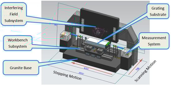
Figure 1.
Structural composition of SBIL system.
This paper focuses on the positioning system stage in SBIL. Before scanning for exposure, the interference light period must be measured, requiring the X-direction positioning system to perform several fixed-length step movements. The position distance of the periodic measurement is 300 mm from the starting point of the positioning system. During the grating manufacturing process, the X-direction positioning system should move forward a certain distance as a grating constant and then wait for the scanning system to complete the exposure of a column in the substrate. According to the characteristics of the manufactured gratings, the positioning system has characteristics of a long stroke, heavy load, and high accuracy. Therefore, a dual-drive positioning system consisting of a macro- and a micro-positioning system was designed. The design uses a friction-driven macro-positioning system to expand the stroke range while using a PZT-drive micro-positioning system to achieve high accuracy.
2.1. Macro-Positioning System
The macro-positioning system adopts a friction-drive method, with the structure shown in Figure 2. The main components include a drive motor, a circular grating, a base coupling, and a drive shaft system. The stroke of the macro-positioning part can reach 1800 mm. To reduce the steady-state vibration of the motor during the stabilization process, a harmonic reducer with a reduction ratio of 160 is between the motor and the tube grating.
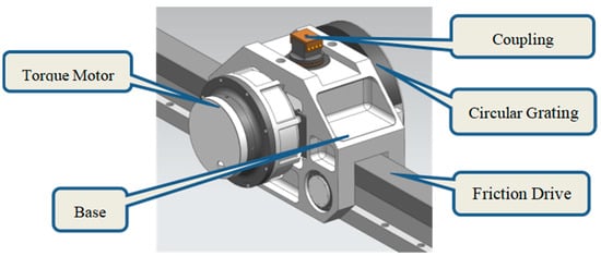
Figure 2.
Composition of the drive mechanism of the macro-positioning system.
The friction drive system and the workbench are connected using a ball and socket shaft coupling with the interference fit, which releases the excess constraints and eliminates backlash during the connection process.
The circular grating was selected from the RESA series of Renishaw, with a resolution of 32 bits. In practical use, the first 28 bits are used. The diameter of the friction wheel d is 60 mm. The circular grating value N, corresponding to each grating rotation, is as follows:
The macro-motion system uses a permanent-magnet synchronous motor (PMSM). We use a space vector control method to improve its control performance. Assuming that the magnetic field applied in the rotor component is sinusoidally distributed in the air gap space and the induced electromotive force in the stator armature winding is also sinusoidally distributed, the mathematical model of the PMSM in the dq-coordinate system using the vector control method is as follows:
where and are the voltages on the d- and q-axes, respectively; and are the currents on the d- and q-axes, respectively; and are the surface PMSM inductances on the d- and q-axes, where ; R is the stator resistance; p is the number of pole pairs; ω is the rotor mechanical angular velocity; J is the moment of inertia; is the electromagnetic torque; is the load torque; B is the friction coefficient; is the torque coefficient; and is the permanent-magnet excitation flux linkage.
The control structure of the macro-positioning system after the PMSM adopts the vector control is shown in Figure 3. The control method of the macro-positioning system is a combination of semi-closed and fully closed loop control. During the system motion, the circular grating data are used for position feedback during the PMSM motion, and the position correction is achieved using the data of the dual-frequency laser interferometer. In addition, this system adds speed feedforward and acceleration feedforward to the traditional PID control, improving the system response.
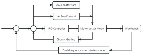
Figure 3.
Control block diagram of macro-positioning system.
2.2. Micro-Positioning System
The motion accuracy of the macro-positioning system is determined based on the system’s machining error, functional error, and step resolution. The error can be on the order of hundreds of nanometers or higher, so a micro-positioning system is needed for compensation. The requirements for the micro-positioning system are high positioning accuracy and high positioning resolution.
The micro-positioning system uses flexible hinges to amplify the displacement of the PZT to achieve a high-precision feed motion. The micro-positioning component is fixed at the bottom of the marble platform and connected to the platform via a coupling, as shown in Figure 4 and Figure 5. The structural design and assembly process comply with the Abbe alignment principle.
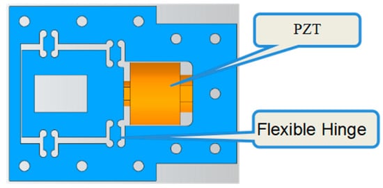
Figure 4.
Flexible hinge and PZT mechanism.
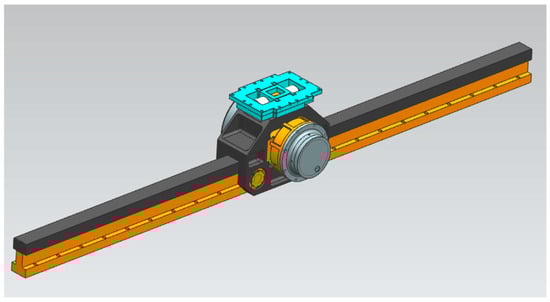
Figure 5.
Installation relationship between micro- and macro-positioning systems.
The micro-positioning system achieves precise position adjustment after the macro-positioning is completed, so the control of the micro-positioning system directly affects the entire system’s positioning accuracy. To eliminate the influence of hysteresis and creep of PZTs on the positioning accuracy, P-235.1S closed-loop piezoelectric ceramics from PI Company are employed. The stroke of the PZT is 15 μm, the static large-signal stiffness is 860 N/μm, and the closed-loop displacement resolution is 0.3 μm. During the motion of the micro-positioning system, the flexible hinge and piezoelectric ceramic are operated at a position with good linearity such that the micro-positioning system is equivalent to a second-order model, as shown in the following equation:
where X(s) is the given position, Y(s) is the displacement of the system, M is the total mass of the system, is the damping coefficient of the workbench, K is the stiffness of the flexible hinge, is the stiffness of the PZT, and is the displacement amplification factor of the flexible hinge. After parameter identification, a second-order model is applied to describe the system as follows:
According to Equations (6) and (7), the values in the model are close to the actual values. Moreover, as shown in Figure 6, the step response of the system is in line with the that of the obtained second-order model.
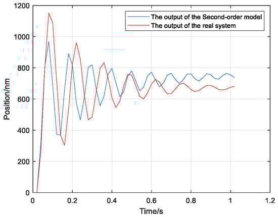
Figure 6.
Output of the second-order model and the real system.
The micro-positioning system uses single-neuron PID control technology. PID control exhibits robustness and ease of implementation. Neural networks are introduced into traditional PID control algorithms to tune PID parameters. A single-neuron network refers to a neural network with only one neuron, which can adjust the parameters of the PID controller online and adapt to different control tasks via learning. This type of network has a much smaller computational load than that of a multi-neuron neural network. Supervised Hebb learning is applied to neural networks with the following calculation:
where e is the position error measured with the interferometer, η is the learning rate of a single neural network, u is the output of the controller, and K is the scaling factor of the neural network. The block diagram of this controller is shown in Figure 7. The micro-positioning system calculates the control variable using a single-neuron PID controller and sends it to the PZT.
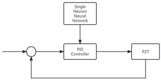
Figure 7.
Single-neuron PID controller.
2.3. Measuring System
To improve the positioning accuracy of the system, we use a dual-frequency laser interferometer as the positional reference for the entire system to correct the position during macro- and micro-positioning. The dual-frequency laser interferometer uses Agilent’s 1071B, and the data acquisition card uses Agilent’s 1231B.
Because of the optical path sensitivity of the dual-frequency laser interferometer to disturbances, we designed a synchronous traction optical path-sealing mechanism. The optical path of the dual frequency laser interferometer is sealed in the synchronous traction optical path-sealing mechanism. When the feed direction moves forward, the optical path-sealing mechanism follows the motion, improving the accuracy of the measurement system.
The parameters of the interferometer are shown in Table 1. For measurement systems, environmental factors are equally important, and we control the laboratory environment as shown in Table 2.

Table 1.
Parameter table of laser interferometer.
Table 2.
Parameter table of environment.
2.4. Stepping Motion Process
The step resolution of the macro-positioning system can reach the submicron level, thus reducing the stroke demand of the micro-positioning system. Therefore, the middle section of the flexible hinge is selected for the micro-positioning system, which has the highest linearity for ease of control.
During the stepping motion, the macro-positioning system is moved to within 2 μm of the desired position, followed by the micro-positioning operation. After the micro-positioning system is positioned within 50 nm of the desired position, it performs low-frequency offset compensation. Figure 8 shows the stepping motion process of the positioning system shown in Figure 9.
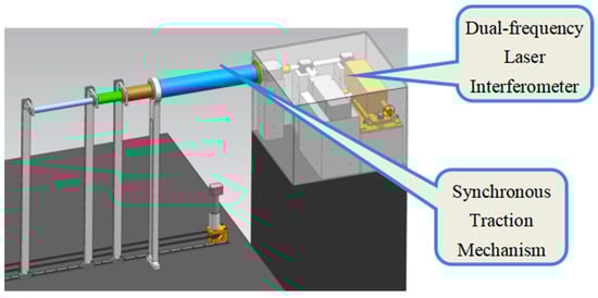
Figure 8.
Measurement system.
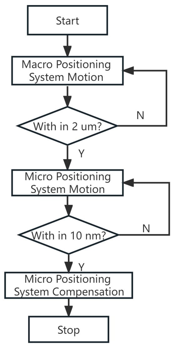
Figure 9.
Workflow of the positioning system.
3. System Error Analysis
3.1. Error Analysis of Dual-Frequency Laser Interferometer
Since the dual-frequency laser interferometer is the position reference of the entire positioning system, its accuracy directly affects the system’s positioning accuracy. Its errors comprise three components: the interferometer systematic error, environmental compensation, and installation error. The main systematic errors of the interferometer include laser wavelength, electronic subdivision, and optical nonlinearity errors.
The wavelength stability of the Agilent 5517D laser used in this system is over 1 h and nm over 50,000 h. The optical nonlinear error of the 10715A interferometer used in this system is nm, and the electronic subdivision error is the position resolution of the interferometer nm.
The main environmental errors are optical thermal drift and wavelength compensation errors. To improve the interferometer accuracy, the laboratory environment temperature should be controlled at 20 ± 0.01 °C, the air pressure at 760 ± 0.12 mmHg, and the humidity at 40 ± 0.8%. Therefore, the compensation accuracy formula for the wavelength tracker 1071B follows:
where R is the electronic subdivision accuracy, AT is the temperature change, and AP is the pressure change. The corresponding measurement distance accuracy is
The optical thermal drift coefficient of interferometer 1071B is 2 nm/°C, and its optical thermal drift error is
The installation error is mainly the cosine error caused by the misalignment of the optical axis in the optical path and the motion axis of the measured device in the practical application of the dual-frequency laser interferometer. For the Agilent 10715A interferometer, the cosine error coefficient is 0.05 ppm when using a plane mirror reflection.
Based on the above analysis, we can conclude that the system accuracy of the dual-frequency laser interferometer is
Furthermore, the accuracy of the dual-frequency laser interferometer in the periodic measurement position is
Finally, the short-term repeatability error of the dual-frequency laser interferometer is
3.2. System Static Stability Experiment and Error Analysis
Air-bearing methods are often used for high-precision positioning systems, but air-bearing tables can exhibit self-excited vibrations when at rest or in a position of closed-loop steady state. The micro-positioning system can compensate for low-frequency oscillations within a certain range, but it cannot suppress high-frequency vibrations effectively. Therefore, the SBIL system requires the positioning system to limit the high-frequency positional vibration after positioning to less than ±15 nm. Within this range, the SBIL system can compensate for the vibration via optical path-sealing mechanisms, among others. However, beyond this range, it is unable to compensate. Since the dual-frequency laser interferometer is the position reference of the entire system, any disturbance in its measurement data can cause positioning errors in the positioning system. Therefore, its measurement noise must be within ±15 nm.
First, we compared the noise of the interferometer with and without the optical path-sealing mechanism. Turn off the air flotation of the macro-positioning system and record the data of the dual frequency laser interferometer when using the optical path sealing mechanism and when not using the optical path sealing mechanism. The results show that when the optical path was open, significant fluctuations occurred in the position data measured with the interferometer. Meanwhile, this fluctuation was significantly improved when the optical path-sealing mechanism was used.
Figure 10 shows that, when using the optical path-sealing mechanism, the peak of the village PV of the interferometer’s measurement noise was 3.34 nm, consistent with the error analysis data in the previous section. The root-mean-square error (RMSE) from the noise was 3.41 nm. Therefore, the optical path-sealing mechanism could suppress the interference caused by external airflow and other factors effectively during the interferometer measurement process. The noise amplitude of 4.4 nm also meets the exposure requirements of the scanning interferometric field.
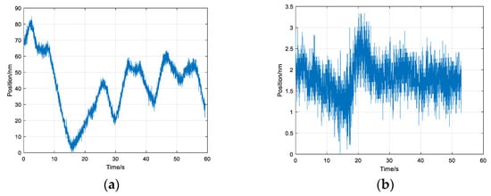
Figure 10.
Interferometer measurement noise experiment; (a) without optical path-sealing mechanism; (b) with optical path-sealing mechanism.
Next, we included the optical path-sealing mechanism, ventilating the air-bearing table, enabling the friction drive motor. We measured the static stability of the table using an interferometer, and we calculated the displacement data equivalent to the angle of the circular grating, as is shown in Figure 11.
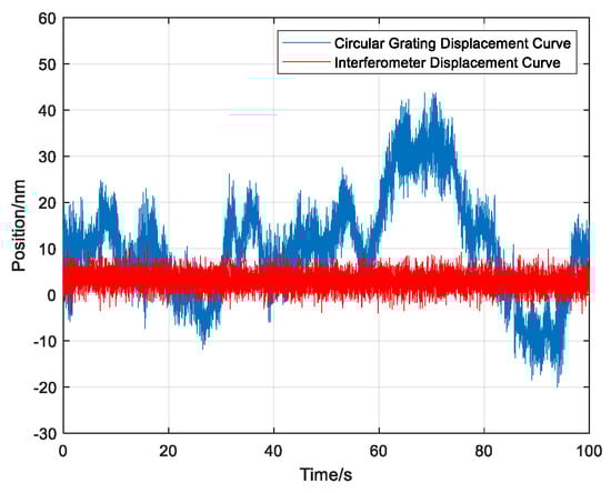
Figure 11.
Comparison of circular grating displacement curve and interferometer displacement curve.
Figure 11 shows that, during the steady-state process of the positioning system, the steady-state jitter at the motor end was between 2 and 10 nm, much smaller than the steady-state position deviation of the dual-frequency laser interferometer. Therefore, the data measured with the dual-frequency laser interferometer were caused by vibrations of the workbench due to the air bearing and other factors. The vibration range was less than ±15 nm, meeting the requirements of the scanning interference field exposure system.
3.3. Error Analysis of Friction Drive Process
The circular grating was used to measure the motor rotation angle, and the interferometer measured the displacement of the positioning system directly. These measurements should be linearly related. However, in the actual process, because of factors such as the system structure, assembly errors, and elastic deformation, a nonlinear relationship may occur between the angular value of the circular grating and the displacement data of the interferometer.
We run the positioning system at a speed of 1 mm/s in the positive direction to a position of 1400 mm, and record the angle value of the circular grating and interferometer data, as shown in Figure 12a–c.
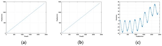
Figure 12.
Friction drive operation experiment; (a) circular grating displacement data; (b) interferometer displacement data; (c) difference between circular grating and interferometer displacement data.
Subtracting the displacement data converted from the circular grating from the displacement value of the interferometer, we obtain the error curve shown in Figure 12c. A periodic error with an amplitude of approximately 0.03 mm is evident, which exists for slightly more than six periods throughout the entire motion process. This error is due to the eccentricity caused by the misalignment of the friction wheel, torque motor, and circular grating. Since the diameter of the friction wheel is 60 mm, we obtain
The calculated value of is consistent with the experimental data, indicating that the eccentricity of the friction wheel is approximately 15 μm. This error can be caused by assembly errors and deformation during the motion of the friction drive mechanism, and suppressing it in practical systems is difficult.
Furthermore, a random error is superimposed on the periodic error caused by structural errors due to the manufacturing process, assembly process, and elastic deformation. The eccentricity and structural errors of the positioning system friction wheel are difficult and costly to suppress simultaneously throughout the entire range of the positioning system. However, in this system, we could reduce the impact of these error factors on the system’s positioning accuracy using a dual-frequency laser interferometer for position closed-loop control.
4. System Stepping Ability Test
According to the workflow of the SBIL system, the positioning system moves a certain distance and then stops to wait for the scanning system to complete the exposure of a column of gratings. Therefore, compared with the system’s dynamic performance, the SBIL system has higher requirements for the positioning accuracy and stability of the table feed system. Both macro- and micro-positioning systems require higher position adjustment capabilities, namely, higher step resolution and lower return error.
4.1. Macro-Positioning System Stepping Ability Test
One advantage of a friction drive compared with other drives is its lack of backlash during motion, allowing for a higher step resolution. To test the stepping ability of the macro-positioning system, we conducted a bidirectional step experiment in the positioning system, causing the friction drive to move in the positive direction for 100 nm in the open-loop mode for five steps and then move in the opposite direction for five steps. The position data of the dual frequency laser interferometer during the movement are recorded as shown in Figure 13.
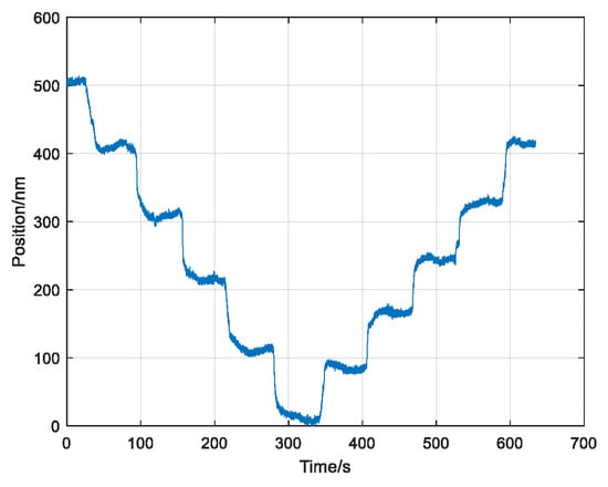
Figure 13.
Bidirectional step experiment at 100 nm.
When the macro-positioning system performed the 100 nm movements, it produced a clear staircase curve. Figure 13 shows that the backlash of the feed system was approximately 30 nm. Figure 14a,b depict curves representing the feed mechanism of the workbench when performing unidirectional step motions of 50 nm and 20 nm. A clear staircase shape is again present when stepping at 50 nm. However, when stepping at 20 nm, the macro-motion mechanism could not produce the staircase behavior. Therefore, the feed capacity of the macro-motion mechanism is superior to 50 nm, sufficient to meet the adjustment requirements of the micro-motion mechanism. Also, we know that the maximum feed capacity of the macro-positioning system is less than 20 nm, which also has certain significance for a system with a load-bearing capacity of 1600 kg.
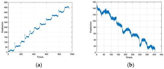
Figure 14.
Macro-positioning system step experiments at 50 nm and 20 nm. (a) Step experiment at 50 nm. (b) Step experiment at 20 nm.
4.2. Micro-Positioning System Stepping Ability Test
The stepping ability of the micro-positioning system directly affects the positioning accuracy of the system. After the PZT was installed on the flexible hinge and a pre-tightening force was applied, its stroke was 4–14.5 μm. To improve the stepping ability of the micro-positioning system, the PZT was moved from 4.5 μm to 14 μm at step sizes of 0.1 μm and 0.5 μm. After each step of the movement was completed and the system stabilized, 50 data points were recorded and averaged to obtain the data shown in Figure 15.
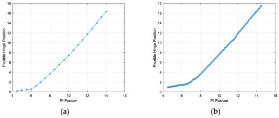
Figure 15.
Step experiments of macro-positioning system at 500 nm and 100 nm; (a) step experiment at 500 nm; (b) step experiment at 100 nm.
Figure 15 shows that the linearity of the micro-positioning system is good in the range of 6–14 μm, and the micro-displacement mechanism can also be effectively executed for a step resolution of 10 nm. The adjustment capability of the micro-positioning system is well connected with that of the macro-positioning system, covering the range that cannot be adjusted with the macro-positioning system.
5. System Positioning Experiment
The scanning interferometric long-exposure system has two working modes: a periodic measurement mode and a scanning exposure mode. Both modes are jointly completed with the macro–micro-positioning system. The periodic measurement mode requires the positioning system to complete a fixed-distance one-way step. The scanning exposure mode requires the positioning system to perform the step-scan motion sequentially within the full stroke range.
5.1. Positioning Experiment of Cycle Measurement Mode
The periodic measurement mode of the scanning interferometric exposure system is simulated, the positioning system is made to perform a step motion with a distance of 1 mm and is stabilized for 10 s, the dual-frequency laser interferometer is used to record the displacement data of the workbench for 10 s at a time interval of 20 ms, and this is repeated five times to obtain the step curve of the positioning system, as shown in the figure. The resulting steady-state error is shown in Figure 16a, the resulting curve is shown in Figure 16b, and the positioning accuracy is shown in Figure 16c.
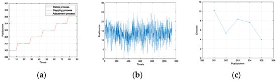
Figure 16.
Simulation cycle measurement experiment. (a) Operating curve. (b) Stability error. (c) Positioning accuracy.
It can be seen that the positioning error of the interferometer measurement during the period measurement phase is 6.3 nm, with an RMS error of 2.49 nm. The position of the period measurement is at 300 mm, and the measurement time is short. Considering the measurement error of the dual-frequency laser interferometer, the positioning error during the period measurement phase can be obtained as follows:
5.2. Positioning Experiment of Scanning Exposure Mode
The scanning exposure mode of the scanning interference field exposure system is simulated, and a step motion at a 2 mm/s speed for a distance of 100 mm is performed until reaching the 1800 mm position. After waiting for each step to complete, a dual-frequency laser interferometer is used to record the displacement data of the positioning system for 10 s at a time interval of 20 ms. This process is repeated three times, and the adjustment time is recorded, as shown in Figure 17.
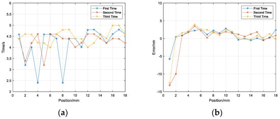
Figure 17.
Full−travel positioning experiment. (a) Positioning accuracy (b) Settling time.
It can be seen that within a range of 1800 mm, the positioning system has a stable time of approximately 5 s, the RMS of the positioning accuracy based on the dual-frequency laser interferometer is approximately 3.45 nm, and the PV of the positioning error is approximately 16.47 nm. Considering the measurement error of the dual-frequency laser interferometer, the error of the feed mechanism within the full stroke range can be obtained as follows:
6. Conclusions
A dual-drive macro–micro high-precision long-stroke high-load precision positioning system for SBIL is designed and analyzed. This system uses a friction drive for the macro-positioning system to achieve a long-stroke range. The micro-positioning system uses PZT and flexible hinges to achieve nanometer-level positioning accuracy. This system uses a dual-frequency laser interferometer as a position reference and uses an optical-path-sealing mechanism to reduce the measurement noise. This study analyzed the measurement error of the system and tested the static stability of the table system and the error of the friction drive mechanism. The measurement noise of the interferometer has a direct impact on the positioning ability of the table, and the processing error of the system can be suppressed via the closed-loop control of the dual-frequency laser interferometer. The stepping ability of the macro-positioning system and the micro-positioning system was tested, and a full-stroke positioning experiment was conducted. The experiment showed that the table can achieve nanometer-level positioning accuracy throughout the full stroke range, which is equally meaningful in the fields of detection and lithography. But the measurement accuracy of the interferometer is the key factor affecting the overall system accuracy. In the next step, we will further study the dynamic indicators, such as improving the positioning accuracy of the system and the positioning speed of the feed system.
Author Contributions
Conceptualization and methodology, Q.C.; optical measurement, R.L. and L.L.; experiment and verification, H.C. and G.Y.; writing—manuscript and editing, H.C. All authors have read and agreed to the published version of the manuscript.
Funding
Youth Innovation Promotion Association of the Chinese Academy of Sciences (grant number 2021215), National Natural Science Foundation of China (grant numbers 62275246 and 62075218), The National Key Scientific Instrument and Equipment Development Project of China (61227901).
Institutional Review Board Statement
Not applicable.
Informed Consent Statement
Not applicable.
Data Availability Statement
The data are contained within this paper.
Conflicts of Interest
The authors declare no conflict of interest.
References
- Schattenburg, M.L.; Chen, C.; Everett, P.N.; Ferrera, J.; Konkola, P.; Smith, H.I. Sub-100 nm metrology using interferometrically produced fiducialsr. J. Vac. Sci. Technol. B Microelectron. Nanometer Struct. Process. Meas. Phenom. 1999, 17, 2692–2697. [Google Scholar] [CrossRef]
- Pati, G.S.; Heilmann, R.K.; Konkola, P.T.; Joo, C.; Chen, C.G.; Murphy, E.; Schattenburg, M.L. Generalized scanning beam interference lithography system for 27 patterning gratings with variable period progressions. J. Vac. Sci. Technol. B Microelectron. Nanometer Struct. Process. Meas. Phenom. 2002, 20, 2617–2621. [Google Scholar] [CrossRef]
- Qiao, X.; Zhang, Y.; Meng, D. The Progress and Perspectives of Nanotechnology Applied in Nontraditional Precision Machining Processes for Advanced Industrial Applications. Recent Pat. Nanotechnol. 2022, 16, 18–29. [Google Scholar] [CrossRef] [PubMed]
- Zhang, L.; Zhang, P.; Jiang, B.; Yan, H. Research trends in methods for controlling macro-micro motion platforms. Nanotechnol. Andprecision Eng. 2023, 6, 035001. [Google Scholar] [CrossRef]
- Tian, Y.; Huo, Z.; Wang, F.; Liang, C.; Shi, B.; Zhang, D. A novel friction-actuated 2-DOF high precision positioning stage with hybrid decoupling structure. Mech. Mach. Theory 2022, 167, 104511. [Google Scholar] [CrossRef]
- Li, X.; Zhang, L.; Jiang, B.; Fang, J.; Zheng, Y. Research trends in China for macro-micro motion platform for microelectronics manufacturing industry. J. Adv. Mech. Des. Syst. Manuf. 2021, 15, JAMDSM0032. [Google Scholar] [CrossRef]
- Iqbal, S.; Malik, A. A review on MEMS based micro displacement amplification mechanisms. Sens. Actuators A Phys. 2019, 300, 111666. [Google Scholar] [CrossRef]
- Xie, X.; Du, R. Research on key techniques of nanometer scale macro-micro dual-drive precision positioning. In Proceedings of the 3rd International Symposium on Advanced Optical Manufacturing and Testing Technologies: Advanced Optical Manufacturing Technologies, Chengdu, China, 8–12 July 2007. [Google Scholar] [CrossRef]
- Lin, R.; Li, Y.; Zhang, Y.; Wang, T.; Wang, Z.; Song, Z.; Dou, Z.; Qian, J. Design of A flexure-based mixed-kinematic XY high-precision positioning platform with large range. Mech. Mach. Theory 2019, 142, 103609. [Google Scholar] [CrossRef]
- Ding, B.; Li, X.; Li, C.; Li, Y.; Chen, S.-C. A survey on the mechanical design for piezo-actuated compliant micro-positioning stages. Rev. Sci. Instrum. 2023, 94, 101502. [Google Scholar] [CrossRef] [PubMed]
- Yang, M.; Zhang, X.; Zhang, C.; Wu, H.; Yang, Y. Design and Performance Research of a Precision Micro-Drive Reduction System without Additional Motion. Micromachines 2022, 13, 1636. [Google Scholar] [CrossRef] [PubMed]
- Zhang, Q.; Zhao, J.; Peng, Y.; Pu, H.; Yang, Y. A novel amplification ratio model of a decoupled XY precision positioning stage combined with elastic beam theory and Castigliano’s second theorem considering the exact loading force. Mech. Syst. Signal Process. 2020, 136, 106473. [Google Scholar] [CrossRef]
- Sharon, A.; Hogan, N.; Hardt, D.E. High bandwidth force regulation and inertia reduction using a macro/micro manipulator system. In Proceedings of the International Conference on Robotics & Automation, Philadelphia, PA, USA, 24–29 April 1988. [Google Scholar] [CrossRef]
- Sharon, A.; Hardt, D. Enhancement of Robot Accuracy using Endpoint Feedback and a Macro/micro Manipulator System. In Proceedings of the American Control Conference, San Diego, CA, USA, 6–8 June 1984. [Google Scholar] [CrossRef]
- Shinno, H.; Yoshioka, H.; Sawano, H. A newly developed long range positioning table system with a sub-nanometer resolution. CIRP Ann. 2011, 60, 403–406. [Google Scholar] [CrossRef]
- Wang, S.; Rong, W.; Wang, L.; Xie, H.; Sun, L.; Mills, J.K. A survey of piezoelectric actuators with long working stroke in recent years: Classifications, principles, connections and distinctions. Mech. Syst. Signal Process. 2019, 123, 591–605. [Google Scholar] [CrossRef]
- Yu, C.; Wu, G.; Wang, Y.; Xiao, Z.; Duan, Y.; Chen, Z. Design of Coaxial Integrated Macro–Micro Composite Actuator With Long-Stroke and High-Precision. IEEE Access 2022, 10, 43501–43513. [Google Scholar] [CrossRef]
- Su, L.; Huang, G.; Huang, R.; Yang, Z. Design of a compact long-stroke high-precision rigid-flexible coupling motion stage driven by linear motor. J. Mech. Sci. Technol. 2022, 36, 5859–5870. [Google Scholar] [CrossRef]
- Wang, F.-C.; Lu, J.-F.; Su, W.-J.; Yen, J.-Y. Precision positioning control of a long-stroke stage employing multiple switching control. Microsyst. Technol. 2022, 28, 319–332. [Google Scholar] [CrossRef]
- Yang, M.; Li, L.; Zhang, C.; Huang, Y.; Wu, H.; Feng, B. Research on Continuous Error Compensation of a Sub-Arc-Second Macro/Micro Dual-Drive Rotary System. Micromachines 2022, 13, 1662. [Google Scholar] [CrossRef] [PubMed]
- Jiang, Z.; Zeng, Y.; Cai, Z. A Large Range Linear Displacement Calibration System Based on Coordinate Measurement and Laser Interference. In Proceedings of the MATEC Web of Conferences, Bandung, Indonesia, 18 April 2018; Volume 232, p. 02016. [Google Scholar] [CrossRef]
- Xu, L.; Tan, Y.; Zhang, S. Full path compensation laser feedback interferometry for remote sensing with recovered nanometer resolutions. Rev. Sci. Instrum. 2018, 89, 033108. [Google Scholar] [CrossRef] [PubMed]
- Liao, Y.; Zhang, Z.; Wang, N.; Chen, Z.; Hao, L.; Yang, X. Environmental compensation of laser interferometer based on ppaper swarm algorithm. Appl. Opt. 2022, 61, 3648–3655. [Google Scholar] [CrossRef]
Disclaimer/Publisher’s Note: The statements, opinions and data contained in all publications are solely those of the individual author(s) and contributor(s) and not of MDPI and/or the editor(s). MDPI and/or the editor(s) disclaim responsibility for any injury to people or property resulting from any ideas, methods, instructions or products referred to in the content. |
© 2023 by the authors. Licensee MDPI, Basel, Switzerland. This article is an open access article distributed under the terms and conditions of the Creative Commons Attribution (CC BY) license (https://creativecommons.org/licenses/by/4.0/).